1
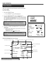
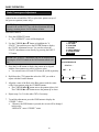
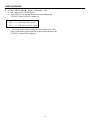
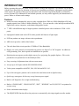
INTRODUCTION
Before operating this projector, please read this manual carefully and completely. This manual will provide you
with the basic instructions for operation of the projector. Installation, preliminary adjustments and procedures
which require the opening of the projector and contact with electrical components should be performed by
service personnel. For continued safe and reliable operation, use only cables supplied by the manufacturer for
power. Adhere to all notes and warnings.
Features
♦ Multi scan circuit automatically locks on video, superdata from 15kHz to 61.lkHz (MultiSync 6PG) and
graphics signals from 15kHz to 90kHz (MultiSync 9PG). You can interface video and high resolution RGB
signals from various computers, workstations and graphics boards.
♦ 7” CRTs with deflection angle 90 degrees produce a detailed picture with a resolution of 1280 x 1024
pixels.
♦ Impregnated cathode used in the CRTs makes possible 800 lumens of light output.
♦ ECP lens produces an image with true color reproduction.
♦ AKB circuit provides a stable white balance.
♦ The wide band video circuit provides of 70MHz of Video Bandwidth.
♦ Display size can be altered to accommodate any picture size from 60” to 300” diagonal. In addition to
ceiling mounting, floor, desk top and rear installations are possible.
♦ Digital point convergence provides high accuracy for a projecting fine graphic displays. (This can be
purchased as an optional item for the MultiSync 6PG)
♦ Easy accessing of adjustment item with on-screen menus.
♦ Accepts up to 100 inputs with the ISS-6OlO/ISS-6OlOG.
♦ Video system compatible with NTSC, PAL, SECAM and NTSC 4.43.
♦ Up to 100 convergence patterns can be stored in the stand alone mode in digital memory.
♦ Quick copy convergence for fast easy set up from one preset signal.
♦ Built in self diagnostics for on sight troubleshooting.
♦ Built in “CROSS HAIR”, “CROSS HATCH”, “DOT”, “WINDOW” and “H (FOCUS)” test patterns for
accurate setup.
♦ Source information status display.
♦ The SEQUENCER function allows the projector to automatically select input signals one after another.
1
INTRODUCTION
Important Safeguards
The following are important safety instructions designed to ensure the long life of your
projector and to prevent fire and shock hazards. Be sure to read these safety instructions
carefully and follow all warnings given below.
Installation
Place the projector on a flat, level surface and in a dry area free from dust and moisture.
Do not place the projector in direct sunlight, near stoves or other heat radiating appliances.
Smoke, steam and exposure to direct sunlight could adversely affect the internal components.
Avoid rough handling when moving your equipment as a strong shock could damage
its internal components. If installing the projector on the ceiling, use only parts supplied
by the manufacturer. Observe all instructions and warnings.
Power supply
The PG-6000 and PG-9000 projector are designed to operate on 120V 60H2, and the PG-6000G
and PG-9000G are designed to operate on 220-240V 50Hz AC power supply.
Make sure your local power supply matches these requirements before operation.
Handle the power cord carefully and avoid excessive bending. A damaged cord may
cause electric shock or fire. If the projector is not to be used for an extended period, remove
the plug from the power outlet.
Cleaning
Unplug the projector from the power outlet before cleaning.
Clean the cabinet and front panel periodically with a soft cloth. If heavily stained, use a
mild detergent solution. Never use strong detergents or solvents such as alcohol or thinner
to clean your projector.
Lens cleaning: Avoid touching the lens surfaces.
Special coating is applied to the lens surfaces.
Consult your dealer for lens cleaning.
Fire and Shock Precautions
Adequate ventilation must be provided to prevent heat build-up inside the projector. Make
sure the ventilation holes are unobstructed.
Keep the inside of the projector free from foreign objects, such as paper clips, nails, paper,
etc. Do not attempt to retrieve such objects yourself or insert metal objects such as wire
and screw-drivers inside the projector. If a hazardous object falls inside the projector,
unplug it immediately and call a qualified electrical repairman for removal.
Do not set liquids on top of the projector.
2
PART NAMES AND FUNCTIONS
Terminal panel
on the front
1. POWER Switch (Main power)
Press to turn the main power on. The STANDBY
indicator is lit.
In this condition you can start up the projector by
pressing the POWER ON button on the remote
control or the POWER button on the rear panel.
Press again to turn the main power off.
6. REMOTE 1 Terminal
This terminal allows external control of the
projector from either the Switcher or from an
external control. When the Switcher is used,
connect to the REMOTE 1 terminal on the back of
the Switcher.
NOTE: Only the ISS-6010/ISS-6010G is
compatible with this projector.
NOTE: When turning off the main power, first
return the projector to the standby condition by
pressing the POWER OFF button on the remote
control or the POWER button on the rear panel
and then turn off the main POWER switch. These
procedures are to protect your projector and the
connected equipment.
7. OPTION 1 Input Terminal
For future system expansion.
8. S-VIDEO Input Terminal
Connect to the S-video output of the external
equipment such as VCR with an S-video output.
2. AC INPUT
Connect the supplied power cord here.
9. VIDEO Input Terminal
Connect to the video output of the external
equipment such as video equipment.
3. REMOTE 2 Jack
When the supplied full function remote control is
used in the wired condition connect the supplied
remote cable here. The wireless control does not
work when the plug of the remote cable is inserted
here.
10. S-VIDEO/ VIDEO Select Switch
Selects either the S-VIDEO input or the VIDEO
input terminal.
4. RGB H/V and V Input Terminals
Connect R, G, B, H (Horizontal sync) and V
(Vertical sync) outputs of the external equipment
(such as the Switcher). If using a component with
a combined sync (SYNC) output, connect it to the
H/V terminal.
5. Remote Sensor
Receives the signal from the supplied remote
control when used in the wireless condition.
4
PART NAMES AND FUNCTIONS
Control panel on the rear
11. POWER Button
Turns the projector on or off when the projector is
in the standby condition (Main Power switch on
and Standby indicator lit).
17. UP Button
Used to increase the selected adjustment level or
move the cursor upward. When used with the
CONTROL button, the UP button works as the
CURSOR > button on the remote control unit.
12. CONTROL Button
Used with other buttons. similar to a shift key on a
typewriter or computer. This is the same with the
CTL button on the remote control.
18. NORMAL/LOAD Button
Returns the adjustment data to the standard level
(NORMAL function).
Pressing this button with holding down the
CONTROL button returns the adjustment data to
the last stored level (LOAD function).
13. OPERATE Button
Press to display the OPERATE menu. You can
select the following adjustment functions from this
menu.
1/PICTURE
4/INPUT SELECT
2/POSITION 5/SOURCE INFO
3/SOUND
6/STATIC
19. Select Counter
Displays "00" in normal operation.
20. REMOTE Indicator
Flashes when the projector receives a signal from
the remote control.
NOTE: The SOUND item is not included in the
“OPERATE” menu on the stand alone mode.
21. STANDBY Indicator
Lights up when the projector's main POWER
switch is on. Flashes when the projector might not
be connected with the Switcher correctly or when
the Switcher might be turned off.
14. ENTER Button
Executes menu selection and switches to selected
input.
15. END Button
Exits t adjustment mode.
22. POWER Indicator
Lights up when the projector is turned on.
16. DOWN Button
Used to decrease the selected adjustment level or
move the cursor downward. When used with the
CONTROL button, the DOWN button works as
the CURSOR < button on the remote control unit.
23. Remote Sensor
Receives the signal from the supplied remote
control when used in the wireless condition.
5
PART NAMES AND FUNCTIONS
Remote control unit
User Remote Control
RC-6010
Full Function Remote Control
RC-6011
NOTE: The full function remote control is designed for setup adjustment. Use the user
remote control for normal operation.
6
PART NAMES AND FUNCTIONS
1. POWER Buttons (ON/OFF)
Press the ON button to turn the projector on when the
projector is in the standby condition. (STANDBY
indicator lit). Press the OFF button to return the
projector to the standby condition.
11. FOCUS Button
Press to enter the FOCUS mode.
12. STATIC Button
Press to enter the STATIC mode. You can adjust the
static convergence.
2. TEST Button
Press to display the”TEST PATTERN” menu from
which you can select the preferred test pattern.
13. POINT Button (when the point convergence
board installed)
Press to enter the POINT mode. You can adjust the
point convergence.
3. ADJUST Button
Press to display the “ADJUST” menu.
14. TILT SKEW ALIGN Button
Press to enter the TILTSKEW ALIGNMENT mode.
You can adjust the tilt and the skew of the projected
image.
4. OPERATE Button
Press to display the “OPERATE” menu.
5. Backlight Switch
Turns the backlight on and off.
15. TILT SKEW CONV Button
Press to enter the TILTSKEW CONVERGENCE
mode. You can adjust the tilt and the skew
convergence for the red or blue CRT.
6. PIC FUNC Button
Press to display the picture adjustment screen.
16. BOW ALIGN Button
Press to enter the BOW ALIGNMENT mode. You can
adjust the horizontal and the vertical bow of the
projected image.
NOTE: Some function items will not be used
depending on the input video signal.
7. SOUND FUNC Button
Press to display the VOLUME adjustment screen. You
can adjust the volume of the ISS-6010/ISS-6010G
Switcher.
17. BOW CONV Button
Press to enter the BOW CONVERGENCE mode. You
can adjust the horizontal and the vertical bow
convergence for the red or blue CRT.
8. PICTURE (PIC) MUTE Button
Press to mute the picture. Press again to return the
picture.
18. AMPLITUDE ALIGN Button
Press to enter the AMPLITUDE ALIGNMENT mode.
You can adjust the horizontal width and the vertical
height of the projected image.
9. SOUND MUTE Button
Press to mute the sound. Press again to return the
sound.
19. AMPLITUDE CONV Button
Press to enter the AMPLITUDE CONVERGENCE
mode. You can adjust the horizontal and the vertical
convergence amplitude for the red or blue CRT.
NOTE: This works only with the ISS-6010/ISS-6010G.
10. DISPLAY Button
Press to turn on or off the ON-SCREEN display.
20. LINEARITY ALIGN Button
Press to enter the LINEARITY ALIGNMENT mode.
You can adjust the horizontal and the vertical linearity
of the projected image.
7
PART NAMES AND FUNCTIONS
21. LINEARITY CONV Button
30. KELVIN Button
Press to enter the LINEARITY CONVERGENCE
mode. You can adjust the horizontal and the vertical
linearity convergence for the red or blue CRT.
Pressing with CTL button controls the LINEARBALANCE convergence.
Press to enter the WHITE BALANCE mode. You can
adjust the white and the black level.
31. POSITION Button
Press to enter the position mode. You can adjust the
horizontal and vertical position and horizontal and
vertical blanking.
22. KEY STONE ALIGN Button
Press to enter the KEY STONE ALIGNMENT mode.
You can adjust the horizontal and the vertical keystone of the projected image. Pressing with CTL
button controls the KEY-BALANCE alignment.
32. R, G and B Buttons
Turn each CRT beam on and off separately. When
using with the CTL button, you can select the CRT to
be adjusted during convergence and center focus
adjustments. Note that the G button is only on the
full function remote control.
23. KEY STONE CONV Button
Press to enter the KEY-STONE CONVERGENCE
mode. You can adjust the horizontal and the vertical
key-stone convergence for the red or blue CRT.
Pressing with CTL button controls the KEYBALANCE convergence.
33. CURSOR Buttons
Used for increasing and decreasing control levels,
cursor movement and convergence adjustments.
24. PIN CUSHION ALIGN Button
34. NORMAL Button
Press to enter the PIN-CUSHION ALIGNMENT
mode. You can adjust the horizontal and the vertical
pin-cushion of the projected image. Pressing with
CTL button controls the PIN-BALANCE alignment.
Returns the adjustments level for each VIDEO or
RGB input signal to the standard level. When pressed
once, the confirmation message will be displayed.
When “YES” is selected and ENTER is pressed, the
data will be returned to the standard level. Pressing
with CTL returns the adjustment data to the last
stored level (LOAD function).
25. PIN CUSHION CONV Button
Press to enter the PIN-CUSHION CONVERGENCE
mode. You can adjust the horizontal and the vertical
pin-cushion convergence for the red or blue CRT.
Pressing with CTL button controls the PINBALANCE convergence.
35. STORE Button
Memorizes the adjustments setting of each VIDEO or
RGB input signal separately. When pressed once, the
confirmation message “STORE?” will be displayed.
When selecting “YES” and ENTER is pressed, the
data will be stored in memory.
26. INPUT Button
Selects menus and switches input signals.
27. HELP Button
36. END Button
Press to display the explanation of the current
selected function and available functions.
Ends the adjustment mode.
37. ENTER Button
28. INPUT LIST Button
Executes menu selection and switches to selected
input.
Press to display the list of the recorded input signals.
29. INFO Button
38. CTL Button
Press to display the various parameters and settings of
the currently displayed image.
Used with other buttons, similar to a shift key on a
typewriter or computer.
39. Remote Control Jack
Insert the plug of the supplied remote cable here when
the full function remote control is used in the wired
condition.
8
PART NAMES AND FUNCTIONS
Battery installation and replacement
User remote control
1. Press down on the battery compartment cover
Full function remote control
1.
and slide the cover in the direction of the arrow.
2. Install the two new batteries, making sure that their
polarity matches the (+) (-) diagrams inside the
battery compartment.
Press down on the battery compartment cover
and slide the cover in the direction of the arrow.
2. Install the two new batteries, making sure that their
polarity matches the (+) (-) diagrams inside the
battery compartment.
3. Close the battery compartment cover.
3. Close the battery compartment cover.
NOTE: The remote control is powered by two 1.5V AA batteries.
Remote control cautions
Use the remote control within the valid operating range within a distance of about 7m (23
ft.) and at 30 degrees angle left and right.
Handling remote control and batteries
• Do not drop or mishandle the remote.
• Do not get the remote wet. If the remote gets wet, wipe it dry immediately.
• Avoid heat and humidity.
• When not using the remote for a long period, remove the batteries.
• Do not use new and old batteries together, or use different types together.
• Do not take apart the batteries, heat them, or throw them into a fire.
• Avoid using the full function remote control as wireless with the backlight switch ON
for an extended period of time. This can cause short battery life.
9
BASIC OPERATION
Projecting the Picture
To project the picture source, proceed as follows:
1) Turn on the main power of the projector.
• Press the POWER switch on the front terminal.
2) Turn on the connected equipment’s power.
3) Turn on the power.
• Press the POWER ON button on the remote control or the POWER button on the rear panel.
4) Select an input signal source by pressing one of the ten INPUT buttons on the remote control. You can also
select a signal from the “INPUT SELECT” list.
• See page 20 “INPUT SELECTION” for more details.
5) Adjust the picture and sound.
• See pages 14 through 18 for more details.
NOTE: The volume function works only with the ISS-6010/ISS-6010G.
6) To turn off the power, press the POWER OFF button on the remote control or the POWER button on the
rear panel.
7) Press the POWER switch on the front terminal to turn off the main power of the projector.
8) Last, turn off the connected equipment power.
10
BASIC OPERATION
Displaying the Menu and Adjustment Screen
You can easily access your desired screen by selecting menus.
Depending upon button selection, your desired screen will be displayed as shown below:
OPERATE menu
NOTE: Examples of the screen display are only when used with the ISS-6010/M-601OG.
n
PIC FUNC
PICTURE menu
- PICTURE 1 / BRIGHT
2 / CONTRAST
3 / COLOR
4 / SHARPNESS
5 / TINT
Adjustment screen
POSITION
OPERATE menu
POSITION menu
- OPERATE -
- POSITION 1 / SHIFT
2 / BLANKING
1 / PICTURE
Adjustment screen
2 / POSITION
OPERATE
3 / SOUND
SOUND FUNC
Adjustment screen
4 / INPUT SELECT
5 / SOURCE INFO
6 / STATIC
•
•
The SOUND item is
not included in the
“OPERATE” menu
on the stand alone
mode.
INPUT SELECT
screen
SOURCE
INFORMATION
screen
INPUT LIST
INFO
STATIC
Adjustment screen
The PIC FUNC, POSITION, SOUND FUNC, INPUT LIST, INFO and STATIC buttons are on the full
function remote control only.
CAUTION: Do not display a bright and still picture for longer than 20 minutes.
This could damage the CRTs.
NOTE: The explanation of the operation on the following pages is for use with the remote
control. You can also operate the projector using the buttons on the control panel of
the projector.
.
11
BASIC OPERATION
Picture Adjustment
To adjust the picture for each input,
proceed as follows:
NOTE: The Color, Sharpness, and Tint controls are not included
in the “PICTURE” menu for RGB signal. The Tint control
is not included in the “PICTURE” menu for SECAM/PAL
signal.
1. Press the OPERATE button.
• The “OPERATE” menu will be displayed.
2. Use the CURSOR por q button to highlight the “lPICTURE”
and press the ENTER button to display the “PICTURE”
menu. You can also select the “PICTURE” menu
directly by pressing the INPUT “1” button.
3. Use the CURSOR p or qbutton to select a picture function
and then press the ENTER button. You can also select an
item directly by pressing an Input button.
• The picture adjustment screen will be displayed.
– OPERATE –
1 / PICTURE
2 / POSITION
3 / SOUND
4 / INPUT SELECT
5 / SOURCE INFO
6 / STATIC
– PICTURE –
1 / BRIGHT
2 / CONTRAST
3 / COLOR
4 / SHARPNESS
5 / TINT
Items to select
• BRIGHT (Bright control)
• CONTRAST (Contrast control)
• COLOR (Color intensity control) • SHARPNESS (Picture detail control)
• TINT (Red and green values control)
NOTE: You can enter the picture adjustment screen directly
using the PIC FUNC button on the full function remote control.
Each time you press the PIC FUNC button, the picture
functions will rotate as follows:
CONTRAST
COLOR
SHARPNESS
TINT
BRIGHT
4. Use the CURSOR buttons to adjust a picture to your preference.
• The CURSOR u or pbutton increases the level.
• The CURSOR t or q button decreases the level.
PICTURE
– BRIGHT –
5. To end this adjustment, press the END button to display the
“STORE?” screen.
• Whenever the END button is pressed, the screen will be
changed in this order:
“PICTURE” menu
“OPERATE” menu
“STORE?” menu
• If the picture adjustments have not been changed, the “STORE ?”
menu will not be displayed.
12
q
60%
BASIC OPERATION
6. Use the CURSOR t or u button to select either “YES” or
“NO” and press the ENTER button.
• Will be returned to the source screen.
STORE ?
YES
Items to select
• YES………..The data will be stored
• NO…………The data will not be stored
•
To exit this mode without storing the current status, select "NO".
If the current status is not stored due to other button operation, the
"STORE ?" menu will be displayed.
13
NO
BASIC OPERATION
Position Adjustment
Adjust the position and screen area
Proceed as follows:
1. Press the OPERATE button.
• The "operate" menu will be displayed
2. Use the CURSOR por q button to highlight the "2/POSITION" line. Press the ENTER button to display the “POSITION’ menu. You can also select the "2/POSITION" menu
directly by pressing the INPUT "2" button.
3. Use the CURSOR p or q button to select either " or
“BLANKING” and press the ENTER button. You can also
select the item directly by pressing the INPUT "1" or “2
button.
• The selected adjustment screen will be displayed.
– OPERATE –
1 / PICTURE
2 / POSITION
3 / SOUND
4 / INPUT SELECT
5 / SOURCE INFO
6 / STATIC
– POSITION –
1 / SHIFT
2 / BLANKING
Items to select
• SHIFT (Position of the picture)
• BLANKING (Screen area)
NOTE: You can enter the position adjustment screen directly using the POSITION button on the full function remote control. The POSITION button will toggle between the
SHIFT and BLANKING.
4. Adjust the position or screen area.
When selecting SHIFT:
Use the CURSOR buttons to move the position of the picture.
• Pressing t or u moves the picture left or right.
• Pressing p or q moves the picture up or down.
NOTE: Adjust to position the picture in the center of the
raster. Over shift-adjusting to the top of the raster may cause
the top of the picture to curve.
14
POSITION
– SHIFT –
H
+10%
q
V
-90%
BASIC OPERATION
When selecting BLANKING:
1) Hold down the CTL button and press CURSOR buttons to
choose the right, left, top or bottom edge.
• The marker on the selected side will turn to a solid color.
POSITION
2) Adjust the blanking using the CURSOR buttons.
– BLANKING –
•
Top (U) and Right (R)--------- Pressing por u increases.
Pressing qor t decreases.
• Bottom (D) and Left (L)-Pressing q or t increases.
Pressing p or u decreases.
5. To end this adjustment, press the END button to display the
"STORE" menu.
• Whenever the END button is pressed, the screen will be
changed in this order.
“POSITION” menu
“OPERATE” menu
“STORE?”
menu
6. Use the CURSOR t or u to select either “YES” or “NO”
and press ENTER.
• If the position adjustments have not been changed, the "STORE"
menu will not be displayed.
• Will be returned to the source screen.
Items to select
• YES………..The data will be stored
• NO…………The data will not be stored
•
To exit this mode without storing the current status, select “NO”.
If the current status is not stored due to other button operation, the
“STORE " menu will be displayed.
15
p
q
vw
vw
q
U
60%
r
s
STORE ?
YES
NO
BASIC OPERATION
Sound Adjustment (only when used with the ISS-6010/ISS-6010G)
Adjust the volume to your preference.
Proceed as follows:
1. Press the OPERATE button.
• The “OPERATE” menu will be displayed.
2. Use the CURSOR p or q button to highlight the "3/
SOUND” line and press the ENTER button to display the
“VOLUME” screen. You can also select the “VOLUME”
screen directly by pressing the INPUT "3" button.
– OPERATE –
1 / PICTURE
2 / POSITION
3 / SOUND
4 / INPUT SELECT
5 / SOURCE INFO
6 / STATIC
NOTE: You can enter the VOLUME adjustment screen directly using the SOUND FUNC button on the full function
remote control.
3. Use the CURSOR buttons to adjust the volume.
• The CURSOR u or p button increases the volume.
The CURSOR t or q button decreases the volume.
SOUND
– VOLUME –
4. To end this adjustments press the END button to display the
“STORE?” menu.
• Whenever the END button is pressed, the screen will be
changed in this order:
“OPERATE” menu
“STORE?” menu
q
60%
STORE ?
5. Use the CURSOR t or u button to select either “YES”
or “NO’ and press the ENTER button.
• If the VOLUME data has not been changed, the “STORE?’
menu will not be displayed.
Items to select
• YES………..The data will be stored
• NO…………The data will not be stored
•
To exit this mode without storing the current status, select “No”.
If the current status is not stored due to other button operation, the
“STORE ?" menu will be displayed.
16
YES
NO
BASIC OPERATION
Input Selection
You can switch from one input to any other input signal
Proceed as follows:
1. Press the OPERATE button.
• The “OPERATE” menu will be displayed.
2. Use the CURSOR p or q button to highlight the "4/INPUT
SELECT" and press ENTER to display the “INPUT SELECT list. You can also select the "INPUT SELECT” list
directly by pressing the INPUT "4" button.
– OPERATE –
1 / PICTURE
2 / POSITION
3 / SOUND
4 / INPUT SELECT
5 / SOURCE INFO
6 / STATIC
NOTE: You can display the “INPUT SELECT” list directly
using the INPUT LIST button on the full function remote
control.
P01
3. Use the CURSOR por q button to highlight the signal to be
switched to and press ENTER to change to the selected input
signal.
NOTE: To advance to the next page or to the previous page,
hold down the CTL button then press the CURSOR p or q
button. To directly access a page, hold down the CTL button
then any one of the INPUT buttons.
4. To end the INPUT SELECT list, press the END button.
• Whenever the END button is pressed, the screen will be
changed in this order:
“OPERATE” men”
Source screen
Continued on the next page.
17
INPUT SELECT
ISS-6010
NO
01
02
03
04
05
06
07
08
09
10
INPUT
M-01 S-01
M-01 S-02
M-01 S-03
M-01 S-04
M-01 S-05
M-01 S-06
M-01 S-07
M-01 S-08
M-01 S-09
M-01 S-10
SW 2 LEVEL
NAME
VTR-1
VTR-2
VIDEO-1
VTR-3
RGB-1
VIDEO-2
VIDEO-3
NTSC
PAL
SECAM
DATE
12/01/92
12/03/92
12/11/92
12/24/92
12/25/92
12/30/92
12/31/92
01/15/93
01/16/93
01/29/93
BASIC OPERATION
NOTE:
• While you are viewing a source screen, you can also select
the input signal directly by pressing the INPUT “1”
through "10" button. In this case INPUT buttons function
as follows:
When using the projector in stand atone operation:
INPUT 1
Changed to the VIDEO input or S-VIDEO
input on the projector
INPUT 2
Changed to the RGB input on the projector
When using the projector with the ISS_6010/ISS-6010G:
INPUT 1 through 10
Changed to the corresponding
number slot of the ISS-6010/
ISS-6010G
When using the projector with two ISS-6010/ISS-6010G
or more:
To switch to another input signal, enter the master slot
number, then the slave slot number by using INPUT buttons and press the ENTER button.
For example: If you want to select a signal from the no. 3
slot of the slave Switcher which is connected to the no. 2
slot of the master Switcher, first press the INPUT "2"
button, then the INPUT “3” button and finally press the
ENTER button.
•
When pressing any one of the INPUT buttons to directly
access one signal among two or more of the same signals,
the projector will output the signal listed in the upper line
automatically. To select the one listed in the lower line,
use the CURSOR p or q button and press the ENTER
button.
INPUT SELECT List Format
Page (P01 to P10)
P01
The Switcher connected
Connection condition of the Switcher
INPUT SELECT
ISS-6010
NO
01
02
03
04
05
06
07
08
09
10
INPUT
M-01
M-01
M-01
M-01
M-01
M-01
M-01
M-01
M-01
M-01
SW 2 LEVEL
S-01
S-02
S-03
S-04
S-05
S-06
S-07
S-08
S-09
S-10
NAME
VTR-1
VTR-2
VIDEO-1
VTR-3
RGB-1
VIDEO-2
VIDEO-3
NTSC
PAL
SECAM
DATE
12/01/92
12/03/92
12/11/92
12/24/92
12/25/92
12/30/92
12/31/92
01/15/93
01/16/93
01/29/93
Date registered
Slot number of the master Switcher
Source name of input signal
Slot number of the sub Switcher
18
BASIC OPERATION
Source Information
This is for viewing the signal information and the current status
of various setting.
Proceed as follows:
1. Press the OPERATE button.
• The “OPERATE” menu will be displayed.
2. Use the CURSOR por q button to highlight the "5/
SOURCE INFO" line and press the ENTER button to display
the “SOURCE INFORMATION” screen. You can also select
the “SOURCE INFORMATION” screen directly by pressing
the INPUT “5” button.
– OPERATE –
1 / PICTURE
2 / POSITION
3 / SOUND
4 / INPUT SELECT
5 / SOURCE INFO
6 / STATIC
NOTE: You can enter the “SOURCE INFORMATION”
screen directly using the INFO button on the full function
remote control.
SOURCE INFORMATION
M-01 S-01
3. To end the “SOURCE INFORMATION” screen, press the
END button.
• Whenever the END button is pressed, the screen will be
changed in this order:
“OPERATE” menu
Source screen
FREQUENCY
fh = ààà .àà
àà KHz
Fv = à à .àà
àà Hz
NAME
LOCK
àààààààà ON
OFF
SYNC DETECT
AUTO
COMP.
MANUAL
SEPA.
G-SYNC
SYNC
HD(+)
NOTE: You can not change NAME, LOCK, SYNC,
DETECT, COLOR TEMP, AKB, COUNTER and TIMER in
this screen.
VD (+)
VIDEO MODE
COLOR TEMP AKB
3200 K
6500 K
ON
9300 K
OFF
COUNTER
TIMER
ààààà ààà :àà
àà
NTSC 3.58
SOURCE INFORMATION Screen Format
Slot number of the master switcher
Slot number of the sub switcher Slot number of the master switcher
SOURCE INFORMATION
M-01 S-01
Scanning frequency
SYNC input polarity
Video color system
NAME
LOCK
àààààààà ON
FREQUENCY
OFF
SYNC DETECT
fh = ààà .àà
àà KHz AUTO
COMP.
Fv = àà .àà
àà Hz
MANUAL SEPA.
G-SYNC
SYNC
COLOR TEMP
AKB
HD(+) VD (+)
3200 K
6500 K
ON
VIDEO MODE
9300 K
OFF
NTSC 3.58
NOTE: The example of the screen display is only when
used with the ISS-6010/ISS-6010G.
COUNTER
TIMER
ààààà
ààà :àà
àà
Counter
19
Timer
Source lock for RGB signal
Sync signal
Color temperature
Auto white balance
BASIC OPERATION
Static Convergence Adjustment
Adjust for the red and blue CRTs to place their pattern on top of
the green test pattern (center only).
NOTE: The static convergence adjustment should be performed for R and B CRT. Carry out the adjustment after displaying a motion picture for 20 minutes or more.
Proceed as follows:
1. Press the OPERATE button.
• The “OPERATE” menu will be displayed.
– OPERATE –
1 / PICTURE
2 / POSITION
3 / SOUND
4 / INPUT SELECT
5 / SOURCE INFO
6 / STATIC
2. Use the CURSOR p or q button to highlight the "6/
STATIC” line and then press the ENTER button to display
the STATIC adjustment screen. You can also select the
STATIC adjustment screen directly by pressing the INPUT
"6" button.
NOTE: The “STATIC” adjustment can also be displayed by
pressing the STATIC button on the full function remote control.
CONVERGENCE
STATIC –
3. Press the R or B button to display the pattern to be aligned
with the Green pattern (as used a reference color).
• You can turn on or off each CRT beam (R and B) separately.
–
4. Hold down the CTL button then select the CRT you wish to
adjust with the R and B buttons.
H
CRT -
-
+10%
q
V
5. Align the center of the Red or the Blue pattern with the center
of the Green pattern using the CURSOR buttons.
• The CURSOR t or u button moves the pattern right or left.
The CURSOR p or q button moves the pattern up or down.
6. Repeat steps 3 to 5 for the other CRTs if necessary.
7. To end this adjustment, press the END button to display the
“STORE ?" menu.
• Whenever the END button is pressed, the screen will be changed
in this order:
“OPERATE” menu “STORE?” menu
20
R
p
-10%
BASIC OPERATION
8. Use the CURSOR t or u button to select either “YES”
or “NO” and press the ENTER button.
• If the STATIC convergence data has not been changed, the
“STORE ?" menu will not be displayed.
Items to select
• YES -----------The data will be stored
• NO ------------The data will not be stored
•
To exit this mode without storing the current status, select “NO”.
If the current status is not stored due to other button operation, the
“STORE ?" menu will be displayed.
21
BASIC OPERATION
Picture and Sound Mute
This function mutes a picture or sound.
To mute a picture or sound:
• Pressing PICTURE (PIC) MUTE mutes a picture.
Pressing SOUND MUTE motes sound.
Pressing again restores the picture (or sound).
NOTE: When picture is muted, no “OPERATE” menu or
“ADJUST’ menu can be accessed.
Normal and Load Function
Adjustment settings can be returned to the standard level or the
previously stored set level.
To return to the standard level (NORMAL):
1. Press the NORMAL button.
• A confirmation message will be displayed.
2. Use the CURSOR t or u button to select “YES”.
XXXXXXXX
DATA
NORMALIZE?
3. Press the ENTER button.
• The NORMAL function will be executed.
YES
NO
NOTE: If you select “NO”, you will exit this mode
suspending current status.
To return to the last stored level (LOAD):
1. Press the NORMAL button while holding down the CTL button.
•
A confirmation message will be displayed.
2. Use the CURSOR t or u button to select "YES".
XXXXXXXX = Adjustment item to be normalized
XXXXXXXX
DATA
LOAD?
3. Press the ENTER button
• The LOAD function will be executed.
YES
NOTE: If you select “NO”, you will exit this mode
suspending current status.
22
NO
XXXXXXXX = Adjustment item to be loaded
SPECIFICATIONS
Projection type
Projection system
Scanning frequency
Retrace time
Video bandwidth
CRT
Lens
Picture size
Resolution
Pixel resolution
Light output
Contrast ratio
High voltage
Input
Convergence
Convergence limits
Warm up time
Setup signal
Power supply
Power consumption
Input current
Safety and regulation
: Refraction type
Projector and screen are separated
: 3 lens and 3 CRT’s in-line
H 15 to 61.1kHz / V 38 to 150Hz (PG-6000/PG-6000G)
H 15 to 90kHz / V 38 to 150Hz (PG-9000/PG-9000G)
: H 4.0 µS (fH 15 to 30kH2)
H 2.5 µS (fH 30 to 9OkHz)
v 350 µS
: 70MHz (-3dB)
: 7 inch liquid cooling
Deflection angle 90 degrees
: Hybrid lenses multilayer coating F1.0
: 60 to 300 inches diagonal
: 1000TV lines
: 1280 × 1024 dots
: 800 lumens (Small area peak high light brightness)
: 1 : 20(HDTV method)
: 32kV
: RGB signal 0.7Vp-p 75ohm positive (BNC)
H/V sync 0.7 to 4.0Vp-p 75ohm negative or positive (BNC)
COMP sync 0.7 to 4.0Vp-p 75ohm negative o r positive (BNC)
Sync on G 0.3 to 0.6Vp-p 75ohm negative (BNC)
Video 1.0Vp-p 75ohm positive (BNC)
or (switchable)
S-video;
Y I .0Vp-p 75ohm positive
C 0.28Vp-p 75ohm (burst level)
Video system NTSC, PAL, SECAM and NTSC4.43
: Digital convergence (Pre-set 100 positions)
Quick copy convergence
Static and wave convergence
Point convergence:
PG6000/PG-6000G Optional
PG-9000/PG-9000G Standard
: Less than 0.2% of V-height
: 20 minutes
: Cross hairs, Cross hatch. Dot, Window pattern, H test pattern
: AC 120V 60Hz (PG6000/PG-9000)
AC 220-240V 50Hz (PG6000G/PG-9000G)
: PG-6000.PG-6000G 430W
PG-9000/PG-9000G 500W
: 5.8A (AC 120V) PG-6000/6.7A (AC 120V) PG-9000
3.8A (AC 220.240V) PG-6000G/4.4A (AC 220-240V) PG-9000G
: PG-6000/PG-9000;
Meets FCC class A requirements
UL Approved (UL 1950)
Governed by IEC 950
CSA certified
Meets DHHS requirements
PG-6000G/PG-9000G;
Meets TÜV GS requirements
Governed by EN 60950 and IEC 950
Meets FTZ class B requirements
Governed by DBP Vfg. 243
Meets x-ray requirements
Governed by § Röntgenverordnung (RöV)
23
SPECIFICATIONS
Cabinet dimensions
Weight
Remote control
Remote control functions
External control
PC control
Supplied accessories
Environment
Sound emission
: 610(W) × 754(D) × 309(H) mm
24 1/8(W) × 29 S/B(D) × 12 1/8(H) inch
: 56 kg/123.4lbs.
: Wired application
Wireless (operating distance 7m/23ft.)
: User remote (RC-6010); Power ON/OFF, Input signal select. Picture mute.
Bright, Contrast, Color I), Sharpness 1), Tint 2), Volume 3), Sound mute, 3),
Source information. Static convergence. Normalize, Enter. End
Full function remote (RC-6011); Test, Display. Help. Information. Input list.
Static focus, Edge focus, H/V position. White balance select, Static convergence,
Wave convergence. Point convergence, H/V amplitude, HIV linearity.
H/V key-stone. H/V pin-cushion, H/V blanking, Tilt, Skew, H/V bow, Store,
Normalize. Enter. End
: Power ON/OFF, Input signal select, Picture mute. Bright, Contrast, Color 1),
Sharpness 1), Tint 2), Volume 3), Sound mute 3), Source information. Static
convergence, Normalize. Enter, End
: Power ON/OFF Input signal select Picture mute. Remote control data input
: Acceptable
: Full function remote control unit (RC-601 I), User remote control unit (RC-6010),
Remote cable 4m/13ft., Remote cable 16m/52ft., AC line cable. Ceiling
mounting kit. User's manual. Installation manual (not included with PG-6000G/
PG-9000G), Picture size spacers. PC control software (one manual
and one floppy disk)
: Temperature 0 to 40 degrees C
Humidity 0 to 90% non-condensing
Storage -10 to 50 degrees c
: PG-6000/PG-9000 45dB
PG-6000G/PG-9000G 70dB (A). Complies with DIN 45635 (or IS0 7779)
1) This works only for VIDEO signals.
2) This works only for NTSC video signals.
3) This works only with the Switcher operation.
Specifications are subject to change without notice.
The dimensions given for the projector do not include protruding parts.
24
APPENDIX
Screen Format in Projecting a Picture
NOTE: The example of the screen display is only when used with the ISS-6010/ISS-6010G.
Date
01/17/93
12:00:00
M-01 S-01
XXXX
Current time
Input
Source name
NOTE:
• Consult your dealer for changing the on-screen display mode.
• If the main power is not supplied to the projector for three days or more, the built-in clock may have to
be reset, If this happens, consult your dealer for setting date and time.
25