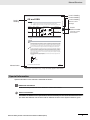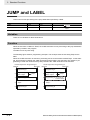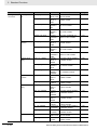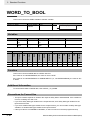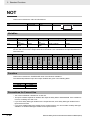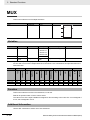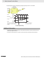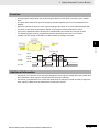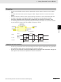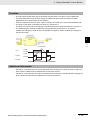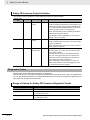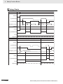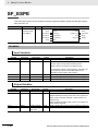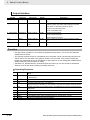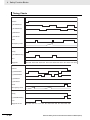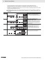
1
Machine Automation Controller NX-series Safety Control Unit Instructions Reference Manual NX-SL@@@@ Z931-E1-02 © OMRON, 2013 All rights reserved. No part of this publication may be reproduced, stored in a retrieval system, or transmitted, in any form, or by any means, mechanical, electronic, photocopying, recording, or otherwise, without the prior written permission of OMRON. No patent liability is assumed with respect to the use of the information contained herein. Moreover, because OMRON is constantly striving to improve its high-quality products, the information contained in this manual is subject to change without notice. Every precaution has been taken in the preparation of this manual. Nevertheless, OMRON assumes no responsibility for errors or omissions. Neither is any liability assumed for damages resulting from the use of the information contained in this publication. Trademarks • Sysmac and SYSMAC are trademarks or registered trademarks of OMRON Corporation in Japan and other countries for OMRON factory automation products. • Windows, Windows 98, Windows XP, Windows Vista, and Windows 7 are registered trademarks of Microsoft Corporation in the USA and other countries. • EtherCAT® is registered trademark and patented technology, licensed by Beckhoff Automation GmbH, Germany. • Safety over EtherCAT® is registered trademark and patented technology, licensed by Beckhoff Automation GmbH, Germany. • The SD and SDHC logos are trademarks of SD-3C, LLC. Other company names and product names in this document are the trademarks or registered trademarks of their respective companies. Introduction Introduction Thank you for purchasing Machine Automation Controller NX-series Safety Control Units. This manual contains information that is necessary to use the NX-series Safety Control Units. Please read this manual and make sure you understand the functionality and performance of the NX-series Safety Control Units before you attempt to use them in a control system. Keep this manual in a safe place where it will be available for reference during operation. Intended Audience This manual is intended for the following personnel, who must also have knowledge of electrical systems (an electrical engineer or the equivalent). • Personnel in charge of introducing FA systems. • Personnel in charge of designing FA systems. • Personnel in charge of installing and maintaining FA systems. • Personnel in charge of managing FA systems and facilities. • Personnel with the qualifications, authority, and responsibility for providing safety at each phase of the lifecycle of the machine: design, installation, operation, maintenance, and disposal. • Personnel with a knowledge of functional safety. For programming, this manual is intended for personnel who understand the programming language specifications in international standard IEC 61131-3 or Japanese standard JIS B3503. Applicable Products This manual covers the following products. • NX-series Safety Control Units NX-SL NX-series Safety Control Unit Instructions Reference Manual (Z931) 1 CONTENTS CONTENTS Introduction .............................................................................................................. 1 Intended Audience....................................................................................................................................... 1 Applicable Products ..................................................................................................................................... 1 Relevant Manuals ..................................................................................................... 7 Manual Structure ...................................................................................................... 8 Page Structure ............................................................................................................................................. 8 Special Information ...................................................................................................................................... 9 Terms and Conditions Agreement ........................................................................ 10 Read and understand this Manual............................................................................................................. 10 Warranty, Limitations of Liability ................................................................................................................ 10 Application Considerations ........................................................................................................................ 11 Disclaimers ................................................................................................................................................ 11 Safety Precautions ................................................................................................. 13 Precautions for Safe Use ....................................................................................... 14 Precautions for Correct Use.................................................................................. 15 Regulations and Standards ................................................................................... 16 Conformance to EC Directives .................................................................................................................. 16 Conformance to EN ISO 13849-1 and EN 62061...................................................................................... 17 Conformance to UL and CSA Standards ................................................................................................... 17 Conformance to KC Standards .................................................................................................................. 18 Software Licenses and Copyrights ............................................................................................................ 18 Unit Versions .......................................................................................................... 19 Unit Versions.............................................................................................................................................. 19 Unit Versions and Sysmac Studio Versions ............................................................................................... 21 Unit Version Notation ................................................................................................................................. 21 Related Manuals ..................................................................................................... 22 Terminology ............................................................................................................ 23 Revision History ..................................................................................................... 24 Sections in this Manual ......................................................................................... 25 Section 1 Introduction to Instructions for Safety Control Units and Interpreting Instruction Descriptions 1-1 Types of Instructions............................................................................................................. 1-2 1-2 Interpreting Instruction Descriptions .................................................................................. 1-3 1-2-1 1-2-2 1-2-3 2 Items ........................................................................................................................................... 1-3 Safety Data Types and Standard Data Types ............................................................................. 1-4 Valid Ranges and Default Values of Variables ............................................................................ 1-5 NX-series Safety Control Unit Instructions Reference Manual (Z931) CONTENTS Section 2 Standard Functions Table of Standard Functions .................................................................................................... 2-2 Execution Control Instructions . . . . . . . . . . . . . . . . . . . . . . . . . . . . . . . . . . . . . . . . . . . . . . . . . . 2-5 JUMP and LABEL.................................................................................................................... 2-6 RETURN.................................................................................................................................. 2-8 Data Type Conversion Instructions . . . . . . . . . . . . . . . . . . . . . . . . . . . . . . . . . . . . . . . . . . . . . . . 2-9 BOOL_TO_INT...................................................................................................................... 2-12 BOOL_TO_DINT ................................................................................................................... 2-13 BOOL_TO_TIME ................................................................................................................... 2-14 BOOL_TO_WORD ................................................................................................................ 2-15 BYTE_TO_INT ...................................................................................................................... 2-16 BYTE_TO_DINT.................................................................................................................... 2-17 WORD_TO_INT .................................................................................................................... 2-18 WORD_TO_DINT .................................................................................................................. 2-20 DWORD_TO_DINT ............................................................................................................... 2-21 BYTE_TO_TIME.................................................................................................................... 2-23 WORD_TO_TIME.................................................................................................................. 2-24 DWORD_TO_TIME ............................................................................................................... 2-25 BYTE_TO_WORD ................................................................................................................. 2-26 WORD_TO_BYTE ................................................................................................................. 2-27 WORD_TO_DWORD ............................................................................................................ 2-28 DINT_TO_BOOL ................................................................................................................... 2-29 INT_TO_BOOL ...................................................................................................................... 2-30 DINT_TO_BYTE .................................................................................................................... 2-31 DINT_TO_DWORD ............................................................................................................... 2-32 DINT_TO_WORD .................................................................................................................. 2-34 INT_TO_BYTE ...................................................................................................................... 2-35 INT_TO_DWORD .................................................................................................................. 2-36 INT_TO_WORD .................................................................................................................... 2-38 DINT_TO_INT ....................................................................................................................... 2-40 INT_TO_DINT ....................................................................................................................... 2-41 DINT_TO_TIME..................................................................................................................... 2-42 INT_TO_TIME ....................................................................................................................... 2-43 TIME_TO_BOOL ................................................................................................................... 2-44 TIME_TO_BYTE.................................................................................................................... 2-45 TIME_TO_DWORD ............................................................................................................... 2-46 TIME_TO_WORD.................................................................................................................. 2-47 TIME_TO_DINT..................................................................................................................... 2-48 TIME_TO_INT ....................................................................................................................... 2-49 WORD_TO_BOOL ................................................................................................................ 2-50 Boolean Operation Instructions . . . . . . . . . . . . . . . . . . . . . . . . . . . . . . . . . . . . . . . . . . . . . . . . . 2-51 AND, OR, and XOR............................................................................................................... 2-52 NOT ....................................................................................................................................... 2-54 NX-series Safety Control Unit Instructions Reference Manual (Z931) 3 CONTENTS Math Instructions . . . . . . . . . . . . . . . . . . . . . . . . . . . . . . . . . . . . . . . . . . . . . . . . . . . . . . . . . . . . . 2-55 ADD ....................................................................................................................................... 2-56 SUB ....................................................................................................................................... 2-58 MUL ....................................................................................................................................... 2-60 DIV......................................................................................................................................... 2-62 Comparison Instructions . . . . . . . . . . . . . . . . . . . . . . . . . . . . . . . . . . . . . . . . . . . . . . . . . . . . . . . 2-65 EQ ......................................................................................................................................... 2-66 NE.......................................................................................................................................... 2-67 LT, LE, GT, and GE ................................................................................................................ 2-68 Other Standard Instructions . . . . . . . . . . . . . . . . . . . . . . . . . . . . . . . . . . . . . . . . . . . . . . . . . . . . 2-71 SEL........................................................................................................................................ 2-72 MUX....................................................................................................................................... 2-74 Section 3 Safety Standard Function Blocks Safety Standard Function Block Instructions ........................................................................... 3-2 SF_CTD................................................................................................................................... 3-3 SF_CTU................................................................................................................................... 3-5 SF_CTUD ................................................................................................................................ 3-7 SF_F_TRIG ........................................................................................................................... 3-10 SF_R_TRIG........................................................................................................................... 3-11 SF_RS ................................................................................................................................... 3-12 SF_SR ................................................................................................................................... 3-13 SF_TOF ................................................................................................................................. 3-14 SF_TON................................................................................................................................. 3-16 SF_TP ................................................................................................................................... 3-18 Section 4 Safety Function Blocks General Rules for Safety Function Blocks............................................................................... 4-2 Safety Function Block Instructions .......................................................................................... 4-8 SF_Antivalent .......................................................................................................................... 4-9 SF_EDM ................................................................................................................................ 4-15 SF_EmergencyStop............................................................................................................... 4-23 SF_EnableSwitch .................................................................................................................. 4-30 SF_Equivalent ....................................................................................................................... 4-36 SF_ESPE .............................................................................................................................. 4-42 SF_GuardLocking.................................................................................................................. 4-49 SF_GuardMonitoring ............................................................................................................. 4-55 SF_ModeSelector.................................................................................................................. 4-61 SF_MutingPar........................................................................................................................ 4-70 SF_MutingPar_2Sensor ........................................................................................................ 4-81 SF_MutingSeq....................................................................................................................... 4-90 SF_OutControl....................................................................................................................... 4-99 SF_SafetyRequest .............................................................................................................. 4-105 4 NX-series Safety Control Unit Instructions Reference Manual (Z931) CONTENTS SF_TestableSafetySensor ....................................................................................................4-111 SF_TwoHandControlTypeII ................................................................................................. 4-121 SF_TwoHandControlTypeIII ................................................................................................ 4-126 Index NX-series Safety Control Unit Instructions Reference Manual (Z931) 5 CONTENTS 6 NX-series Safety Control Unit Instructions Reference Manual (Z931) Relevant Manuals Relevant Manuals Two manuals, the NX-series Safety Control Unit User’s Manual and the NX-series Safety Control Unit Instructions Reference Manual, provide basic information on the NX-series Safety Control Units. Most operations are performed from the Sysmac Studio Automation Software. Refer to the Sysmac Studio Version 1 Operation Manual (Cat. No. W504) for information on the Sysmac Studio. Other manuals are necessary for specific system configurations and applications. Read all of the manuals that are relevant to your system configuration and application to make the most of the NX-series Safety Control Unit. Manuals NX Series Basic information NJ-series Troubleshooting Manual NJ-series Instructions Reference Manual NJ-series CPU Unit Built-in EtherCAT Port User’s Manual NJ-series CPU Unit Software User’s Manual NJ-series CPU Unit Hardware User’s Manual NX-series Data Reference Manual NX-series EtherCAT Coupler Unit User’s Manual NX-series Safety Control Unit Instruction Reference Manual NX-series Safety Control Unit User’s Manual Purpose of use NJ Series Learning about Safety Control Units ● Mounting, installing, and making hardware settings for Safety Control ● ● ● ● Units Making software settings for Safety ● ● ● Control Units Creating safety programs ● ● Verifying and debugging safety pro● ● grams Troubleshooting Safety Control Units ● ▲ ▲ ▲ ▲ ▲ Maintaining Safety Control Units ● ● Learning the application methods of ● ● ● ● NJ-series Controllers *1 The NJ-series Troubleshooting Manual introduces the error management concepts and error items. Refer to the manuals that are indicated with triangles for details on errors for the corresponding Units. NX-series Safety Control Unit Instructions Reference Manual (Z931) 7 Manual Structure Manual Structure Page Structure The following page structure is used in this manual. Ladder Diagram Instructions 2 Level-2 heading Ladder Diagram Instructions Instruction Manual name Name Level-1 section number Gives the number of the section. Page LD and LDN Load/ Load NOT 2-14 AND and ANDN AND/ AND NOT 2-16 OR and ORN OR/ OR NOT 2-18 Out and OutNot Output/ Output NOT 2-20 NJ-series Instructions Reference Manual (W502) Level-2 heading 2-13 This page is for illustration only. It may not literally appear in this manual. 8 NX-series Safety Control Unit Instructions Reference Manual (Z931) Manual Structure 2 Instruction Descriptions OR: Takes the logical OR of the value of a BOOL variable and the execution condition. ORN: Takes the logical OR of the inverse of the value of a BOOL variable and the execution condition. Instruction Name FB/FUN OR Graphic expression --- ST expression result:=vBool1 OR vBool2; Variable Variable Variable Upward differentiation Downward Downward differentiation differentiation Variable Variable Upward differentiation Downward differentiation Variable ORN OR NOT --- result:=vBool1 OR NOT vBool2; Variable Give the current headings. 2 Level-1 section number OR and ORN OR Ladder Diagram Instructions OR and ORN Level-3 heading Level-1 heading Level-2 heading Level-3 heading Gives the number of the section. Variables None Function OR The OR instruction takes the logical OR of the value of a specified BOOL variable and the execution condition and outputs it to the next instruction. Use the OR instruction for a NO bit connected in parallel with the previous instruction. Use the OR instruction to configure a logical OR between an NO bit and one of the following: a LD or LDN instruction connected directly to the bus bar, or the logic block starting with a LD or LDN instruction and ending with the instruction immediately before the OR instruction. ORN The ORN instruction takes the logical OR of the inverse of the value of a specified BOOL variable and the execution condition and outputs it to the next instruction. Use the ORN instruction for a NC bit connected in parallel with the previous instruction. Use the ORN instruction to configure a logical OR between an NC bit and one of the following: a LD or LDN instruction connected directly to the bus bar, or the logic block starting with a LD or LDN instruction and ending with the instruction immediately before the ORN instruction. The following figure shows a programming example of the OR instruction. It takes the logical OR of variable A and variable B and outputs it to variable C. LD instruction C A B Out instruction OR instruction Manual name NJ-series Instructions Reference Manual (W502) 2-17 This page is for illustration only. It may not literally appear in this manual. Special Information Special information in this manual is classified as follows: Additional Information References are provided to more detailed or related information. Version Information Information on differences in specifications and functionality for CPU Units and EtherCAT Coupler Units with different unit versions and for different versions of the Sysmac Studio is given. NX-series Safety Control Unit Instructions Reference Manual (Z931) 9 Terms and Conditions Agreement Terms and Conditions Agreement Read and understand this Manual Please read and understand this catalog before purchasing the products. Please consult your OMRON representative if you have any questions or comments. Warranty, Limitations of Liability Warranties Exclusive Warranty Omron’s exclusive warranty is that the Products will be free from defects in materials and workmanship for a period of twelve months from the date of sale by Omron (or such other period expressed in writing by Omron). Omron disclaims all other warranties, express or implied. Limitations OMRON MAKES NO WARRANTY OR REPRESENTATION, EXPRESS OR IMPLIED, ABOUT NON-INFRINGEMENT, MERCHANTABILITY OR FITNESS FOR A PARTICULAR PURPOSE OF THE PRODUCTS. BUYER ACKNOWLEDGES THAT IT ALONE HAS DETERMINED THAT THE PRODUCTS WILL SUITABLY MEET THE REQUIREMENTS OF THEIR INTENDED USE. Omron further disclaims all warranties and responsibility of any type for claims or expenses based on infringement by the Products or otherwise of any intellectual property right. Buyer Remedy Omron’s sole obligation hereunder shall be, at Omron’s election, to (i) replace (in the form originally shipped with Buyer responsible for labor charges for removal or replacement thereof) the non-complying Product, (ii) repair the non-complying Product, or (iii) repay or credit Buyer an amount equal to the purchase price of the non-complying Product; provided that in no event shall Omron be responsible for warranty, repair, indemnity or any other claims or expenses regarding the Products unless Omron’s analysis confirms that the Products were properly handled, stored, installed and maintained and not subject to contamination, abuse, misuse or inappropriate modification. Return of any Products by Buyer must be approved in writing by Omron before shipment. Omron Companies shall not be liable for the suitability or unsuitability or the results from the use of Products in combination with any electrical or electronic components, circuits, system assemblies or any other materials or substances or environments. Any advice, recommendations or information given orally or in writing, are not to be construed as an amendment or addition to the above warranty. See http://www.omron.com/global/ or contact your Omron representative for published information. Limitation on Liability; Etc OMRON COMPANIES SHALL NOT BE LIABLE FOR SPECIAL, INDIRECT, INCIDENTAL, OR CONSEQUENTIAL DAMAGES, LOSS OF PROFITS OR PRODUCTION OR COMMERCIAL LOSS IN ANY WAY CONNECTED WITH THE PRODUCTS, WHETHER SUCH CLAIM IS BASED IN CONTRACT, WARRANTY, NEGLIGENCE OR STRICT LIABILITY. Further, in no event shall liability of Omron Companies exceed the individual price of the Product on which liability is asserted. 10 NX-series Safety Control Unit Instructions Reference Manual (Z931) Terms and Conditions Agreement Application Considerations Suitability of Use Omron Companies shall not be responsible for conformity with any standards, codes or regulations which apply to the combination of the Product in the Buyer’s application or use of the Product. At Buyer’s request, Omron will provide applicable third party certification documents identifying ratings and limitations of use which apply to the Product. This information by itself is not sufficient for a complete determination of the suitability of the Product in combination with the end product, machine, system, or other application or use. Buyer shall be solely responsible for determining appropriateness of the particular Product with respect to Buyer’s application, product or system. Buyer shall take application responsibility in all cases. NEVER USE THE PRODUCT FOR AN APPLICATION INVOLVING SERIOUS RISK TO LIFE OR PROPERTY WITHOUT ENSURING THAT THE SYSTEM AS A WHOLE HAS BEEN DESIGNED TO ADDRESS THE RISKS, AND THAT THE OMRON PRODUCT(S) IS PROPERLY RATED AND INSTALLED FOR THE INTENDED USE WITHIN THE OVERALL EQUIPMENT OR SYSTEM. Programmable Products Omron Companies shall not be responsible for the user’s programming of a programmable Product, or any consequence thereof. Disclaimers Performance Data Data presented in Omron Company websites, catalogs and other materials is provided as a guide for the user in determining suitability and does not constitute a warranty. It may represent the result of Omron’s test conditions, and the user must correlate it to actual application requirements. Actual performance is subject to the Omron’s Warranty and Limitations of Liability. Change in Specifications Product specifications and accessories may be changed at any time based on improvements and other reasons. It is our practice to change part numbers when published ratings or features are changed, or when significant construction changes are made. However, some specifications of the Product may be changed without any notice. When in doubt, special part numbers may be assigned to fix or establish key specifications for your application. Please consult with your Omron’s representative at any time to confirm actual specifications of purchased Product. Errors and Omissions Information presented by Omron Companies has been checked and is believed to be accurate; however, no responsibility is assumed for clerical, typographical or proofreading errors or omissions. NX-series Safety Control Unit Instructions Reference Manual (Z931) 11 Terms and Conditions Agreement 12 NX-series Safety Control Unit Instructions Reference Manual (Z931) Safety Precautions Safety Precautions Refer to the following manual for safety precautions. • NX-series Safety Control Unit User’s Manual (Cat No. Z930) NX-series Safety Control Unit Instructions Reference Manual (Z931) 13 Precautions for Safe Use Precautions for Safe Use Refer to the following manual for precautions for the safe use of the Safety Control Unit. • NX-series Safety Control Unit User’s Manual (Cat No. Z930) 14 NX-series Safety Control Unit Instructions Reference Manual (Z931) Precautions for Correct Use Precautions for Correct Use Refer to the following manual for precautions for the correct use of the Safety Control Unit. • NX-series Safety Control Unit User’s Manual (Cat No. Z930) NX-series Safety Control Unit Instructions Reference Manual (Z931) 15 Regulations and Standards Regulations and Standards The NX-series Safety Control Units are certified for the following standards. Certification body TÜV Rheinland *1 UL Standards • EN ISO 13849-1:2008 + AC:2009 • EN 61000-6-2:2005 • EN ISO 13849-2:2012 • EN 61000-6-4:2007 • IEC 61508 parts 1-7:2010 • NFPA 79:2012 • EN 62061:2005 • ANSI RIA 15.06-1999 • EN 61131-2:2007 • ANSI B11.19-2010 • EN ISO 13850:2008 • UL1998 • EN 60204-1:2006 + A1:2009 + AC:2010 • IEC 61326-3-1:2008 • cULus: Listed (UL508) and ANSI/ISA 12.12.01 *1. Certification was received for applications in which OMRON FSoE devices are connected to each other. The NX-series Safety Control Units allow you to build a safety control system that meets the following standards. • Requirements for SIL 3 (Safety Integrity Level 3) in IEC 61508, EN 62061 (Functional Safety of Electrical/Electronic/Programmable Electronic Safety-related Systems) • Requirements for PLe (Performance Level e) and for safety category 4 in EN ISO13849-1 The NX-series Safety Control Units are also registered for C-Tick and KC compliance. Conformance to EC Directives Applicable Directives • EMC Directive • Machinery Directive Concepts EMC Directives OMRON devices that comply with EC Directives also conform to the related EMC standards so that they can be more easily built into other devices or the overall machine. The actual products have been checked for conformity to EMC standards.*1 Whether the products conform to the standards in the system used by the customer, however, must be checked by the customer. EMC-related performance of the OMRON devices that comply with EC Directives will vary depending on the configuration, wiring, and other conditions of the equipment or control panel on which the OMRON devices are installed. The customer must, therefore, perform the final check to confirm that devices and the overall machine conform to EMC standards. *1. Applicable EMC (Electromagnetic Compatibility) standards are as follows: EMS (Electromagnetic Susceptibility): EN 61131-2 EMI (Electromagnetic Interference): EN 61131-2 (Radiated emission: 10-m regulations). Machinery Directive The Machinery Directive demands that the safety components that are used to provide safety for the relevant machinery are used according to the required levels of safety. The applicable directives are EN ISO 13849-1:2008 and EN 62061 SIL CL3. 16 NX-series Safety Control Unit Instructions Reference Manual (Z931) Regulations and Standards Conformance to EC Directives The NX-series Units comply with EC Directives. To ensure that the machine or device in which the NX-series Units are used complies with EC Directives, the following precautions must be observed. • The NX-series Units must be installed within a metallic control cabinet. • You must meet the following conditions for the DC power supplies that are connected as the Unit power supplies and I/O power supplies for the NX-series Units. (a) Use reinforced insulation or double insulation. (b) Ensure an output hold time of 20 ms min. (c) Use an SELV power supply that meets the requirements of IEC/EN 60950-1 and EN 50178. Do not allow the power supply cable length to exceed 3 m. We recommend that you use the OMRON S8JX-series Power Supplies. EMC standard compliance was confirmed for the recommended Power Supplies. • NX-series Units that comply with EC Directives also conform to the Common Emission Standard (EN 61131-2). Radiated emission characteristics (10-m regulations) may vary depending on the configuration of the control panel used, other devices connected to the control panel, wiring, and other conditions. You must therefore confirm that the overall machine or equipment in which the NX-series Units are used complies with EC Directives. • This is a Class A product (for industrial environments). In a residential environment, it may cause radio interference. If radio interference occurs, the user may be required to take appropriate measures. Conformance to EN ISO 13849-1 and EN 62061 International standards EN ISO 13849-1 and EN 62061 demand that process controls be in place for the creation of safety-related software when building a safety control system that uses Safety Control Units. The process control must ensure that the software is easy to read, understand, test, and maintain to avoid system failures during each phase (i.e., general software design, safety circuit system design, and software upgrades) of the software design lifecycle. This means that process controls must also be in place for the design and development of safety software, such as for equipment and machinery that use function blocks that are provided by the Safety Control Units. It is the customer’s responsibility to conform with all standards. Conformance to UL and CSA Standards The NX-series Safety Control Units comply with the following UL and CSA standards. The application conditions for standard compliance are defined. Refer to the Instruction Sheet that is provided with each Unit before application. NX-series Safety Control Unit Instructions Reference Manual (Z931) 17 Regulations and Standards Conformance to KC Standards Observe the following precaution if you use NX-series Units in Korea. Class A Device (Broadcasting Communications Device for Office Use) This device obtained EMC registration for office use (Class A), and it is intended to be used in places other than homes. Sellers and/or users need to take note of this. Software Licenses and Copyrights This product incorporates certain third party software. The license and copyright information associated with this software is available at http://www.fa.omron.co.jp/nj_info_e/. 18 NX-series Safety Control Unit Instructions Reference Manual (Z931) Unit Versions Unit Versions This section describes the notation that is used for unit versions, the confirmation method for unit versions, and the relationship between unit versions and Sysmac Studio versions. Unit Versions A “unit version” has been introduced to manage the Units in the NX Series according to differences in functionality accompanying Unit upgrades. Notation of Unit Versions on Products The unit version is given with the Unit specifications on the side of the Unit or in the notched area. Notched area Unit specifications Lot number and unit version Unit model number LOT No. Lot number Unit version The following information is provided in the Unit specifications on the Unit. Name Unit model number Function Gives the model of the Unit. Unit version Gives the unit version of the Unit. Lot number Gives the lot number of the Unit. DDMYY: Lot number, : Used by OMRON. “M” gives the month (1 to 9: January to September, X: October, Y: November, Z: December) NX-series Safety Control Unit Instructions Reference Manual (Z931) 19 Unit Versions The following information is provided in the notched area on the Unit. Name Lot number and unit version Function Gives the lot number and unit version of the Unit. • DDMYY: Lot number, : Used by OMRON. “M” gives the month (1 to 9: January to September, X: October, Y: November, Z: December) • 1: Unit version The decimal portion of the unit version is omitted. (It is provided in the Unit specifications.) Confirming Unit Versions with the Sysmac Studio You can use the Unit Production Information on the Sysmac Studio to check the unit versions EtherCAT Coupler Unit and NX Units. 1 Double-click EtherCAT under Configurations and Setup in the Multiview Explorer, and then double-click the EtherCAT Coupler Unit. Or, right-click the EtherCAT Coupler Unit and select Edit from the menu. The Edit Slave Terminal Configuration Tab Page is displayed. You can also display the Edit Slave Terminal Configuration Tab Page with any of the following operations. Double-click EtherCAT under Configurations and Setup in the Multiview Explorer, right-click the EtherCAT Coupler Unit in the EtherCAT Configuration Edit Tab Page, and select Edit Slave Terminal Configuration. Or, select the EtherCAT Coupler Unit on the EtherCAT Configuration Edit Tab Page click the Edit Slave Terminal Configuration Button. 2 3 Go online. Right-click the EtherCAT Coupler Unit and select Display Production Information from the menu. The Production Information Dialog Box is displayed. Simple Display Detailed Display In this example, “Ver.1.0” is displayed next to the Unit model. The following items are displayed. • Slot number • Unit model number • Unit version • Serial number • Lot number 20 NX-series Safety Control Unit Instructions Reference Manual (Z931) Unit Versions • Hardware version • Software version The software version is displayed only for Units that contain software. Unit Versions and Sysmac Studio Versions The functions that are supported depend on the unit version of the Unit. The version of Sysmac Studio that supports the functions that were added for an upgrade is also required to use those functions. Refer to the NX-series Safety Control Unit User’s Manual (Cat. No. Z930) for the relationship between the unit versions of the CPU Units and the Sysmac Studio versions, and for the functions that are supported by each unit version. Unit Version Notation In this User’s Manual, unit versions are specified as shown in the following table. Unit version in Unit specifications on the product Ver. 1. or later Notation in this manual Unit version 1.0 or later NX-series Safety Control Unit Instructions Reference Manual (Z931) Remarks Unless unit versions are specified, the information in this manual applies to all unit versions. 21 Related Manuals Related Manuals The following manuals are related. Use these manuals for reference. Manual name Cat. No. Model numbers Application Description NX-series Safety Con- Z930 trol Unit User’s Manual NX-SL@@@@ NX-SI@@@@ NX-SO@@@@ Learning how to use NX-series Safety Control Units. The hardware, setup methods, and functions of the NX-series Safety Control Unit are described. NX-series Safety Control Unit Instructions Reference Manual Z931 NX-SL@@@@ Learning about the specifications of instructions for the Safety CPU Unit. The instructions for the Safety CPU Unit are described. When programming, use this manual together with the NX-series Safety Control Unit User’s Manual (Cat. No. Z930). NX-series EtherCAT® Coupler Unit User’s Manual W519 NX-ECC@@@ Leaning how to use an NX-series EtherCAT Coupler Unit and EtherCAT Slave Terminals. The following items are described: the overall system and configuration methods of an EtherCAT Slave Terminal (which consists of an NX-series EtherCAT Coupler Unit and NX Units), and information on hardware, setup, and functions to set up, control, and monitor NX Units through EtherCAT. NX-series Data Reference Manual W525 NX-@@@@@@ Referencing lists of the data that is required to configure systems with NX-series Units. Lists of the power consumptions, weights, and other NX Unit data that is required to configure systems with NX-series Units are provided. NJ-series CPU Unit Hardware User’s Manual W500 NJ501-@@@@ NJ301-@@@@ Learning the basic specifications of the NJ-series CPU Units, including introductory information, designing, installation, and maintenance. Mainly hardware information is provided. An introduction to the entire NJ-series system is provided along with the following information on the CPU Unit. • Features and system configuration • Overview • Part names and functions • General specifications • Installation and wiring • Maintenance and Inspection Use this manual together with the NJ-series CPU Unit Software User's Manual (Cat. No. W501). NJ-series CPU Unit Software User’s Manual W501 NJ501-@@@@ NJ301-@@@@ Learning how to program and set up an NJ-series CPU Unit. Mainly software information is provided. The following information is provided on an NJ-series CPU Unit. • CPU Unit operation • CPU Unit features • Initial settings • Programming based on IEC 61131-3 language specifications Use this manual together with the NJ-series CPU Unit Hardware User's Manual (Cat. No. W500). NJ-series CPU Unit Built-in EtherCAT® Port User’s Manual W505 NJ501-@@@@ NJ301-@@@@ Using the built-in EtherCAT port on an NJ-series CPU Unit. Information on the built-in EtherCAT port is provided. This manual provides an introduction and provides information on the configuration, features, and setup. Use this manual together with the NJ-series CPU Unit Hardware User's Manual (Cat. No. W500) and NJ-series CPU Unit Software User's Manual (Cat. No. W501). NJ-series Instructions Reference Manual W502 NJ501-@@@@ NJ301-@@@@ Learning detailed specifications on the basic instructions of an NJ-series CPU Unit. The instructions in the instruction set (IEC 61131-3 specifications) are described. When programming, use this manual together with the NJ-series CPU Unit Hardware User's Manual (Cat. No. W500) and NJ-series CPU Unit Software User's Manual (Cat. No. W501). NJ-series Troubleshooting Manual W503 NJ501-@@@@ NJ301-@@@@ Learning about the errors that may be detected in an NJ-series Controller. Concepts on managing errors that may be detected in an NJ-series Controller and information on individual errors are described. Use this manual together with the NJ-series CPU Unit Hardware User's Manual (Cat. No. W500) and NJ-series CPU Unit Software User's Manual (Cat. No. W501). Sysmac Studio Version 1 Operation Manual W504 SYSMACSE2@@@ Learning about the operating procedures and functions of the Sysmac Studio. Describes the operating procedures of the Sysmac Studio. 22 NX-series Safety Control Unit Instructions Reference Manual (Z931) Terminology Terminology Refer to the NX-series Safety Control Unit User’s Manual (Cat. No. Z930) for the definitions of terms that are used in this manual. NX-series Safety Control Unit Instructions Reference Manual (Z931) 23 Revision History Revision History A manual revision code appears as a suffix to the catalog number at the bottom left of the front and back covers of the manual. Cat. No. Z931-E1-02 Revision code Revision code 01 02 24 Date June 2013 September 2013 Revised content Original production Corrected mistakes. NX-series Safety Control Unit Instructions Reference Manual (Z931) Sections in this Manual Sections in this Manual 1 1 Introduction to Instructions for Safety Control Units and Interpreting Instruction Descriptions 2 3 2 Standard Functions 4 3 Safety Standard Function Blocks 4 Safety Function Blocks I Index NX-series Safety Control Unit Instructions Reference Manual (Z931) I 25 Sections in this Manual 26 NX-series Safety Control Unit Instructions Reference Manual (Z931) 1 Introduction to Instructions for Safety Control Units and Interpreting Instruction This section provides an introduction to the instructions for Safety Control Units and tells how to interpret the instruction descriptions. 1-1 Types of Instructions . . . . . . . . . . . . . . . . . . . . . . . . . . . . . . . . . . . . . . . . . . . 1-2 1-2 Interpreting Instruction Descriptions . . . . . . . . . . . . . . . . . . . . . . . . . . . . . . 1-3 1-2-1 1-2-2 1-2-3 Items . . . . . . . . . . . . . . . . . . . . . . . . . . . . . . . . . . . . . . . . . . . . . . . . . . . . . . . . . 1-3 Safety Data Types and Standard Data Types . . . . . . . . . . . . . . . . . . . . . . . . . . 1-4 Valid Ranges and Default Values of Variables . . . . . . . . . . . . . . . . . . . . . . . . . 1-5 NX-series Safety Control Unit Instructions Reference Manual (Z931) 1-1 1 Introduction to Instructions for Safety Control Units and Interpreting Instruction Descriptions 1-1 Types of Instructions The following three types of instructions can be used with the Safety Control Units. Type Standard functions Safety standard function blocks Safety function blocks Description These function instructions do not use safety data. They include program execution control instructions, data type conversion instructions, Boolean operation instructions, math instructions, comparison instructions, etc. These function block instructions use safety data. They include counter instructions, up/down trigger instructions, timer instructions, etc. These function block instructions use safety data and are based on the safety standards defined by PLCopen. They include an antivalent instruction, emergency stop instruction, etc. Instruction specifications are provided starting from section 2. Precautions for Correct Use Some of the instructions have the same names as the instructions that are supported by the NJ-series CPU Units. Operating specifications, however, are different. 1-2 NX-series Safety Control Unit Instructions Reference Manual (Z931) 1 Introduction to Instructions for Safety Control Units and Interpreting Instruction Descriptions Interpreting Instruction Descriptions The notation that is used to describe instructions is explained in this section. 1-2-1 1-2 Interpreting Instruction Descriptions 1-2 Items Item Instruction Name FB/FUN Graphic expression Description The instruction word is given. The name of the instruction is given. Whether the instruction is a function block (FB) instruction or a function (FUN) instruction is given. The figure that represents the instruction in a function block diagram is given. Example for a FUN Instruction Example for a FB Instruction Instruction word ADD Input variable name Instance specification SF_CTU_instance SF_CTU CU RESET Output variable name Q CV PV Instance specification: An instance of an instruction is indicated by “XX_instance” above a FB instruction. You must assign an instance name to any instance of an instruction that you specify. NX-series Safety Control Unit Instructions Reference Manual (Z931) 1-3 1 1-2-1 Items The following items are provided. The order of the items is not the same for all instructions. If there are items that are specific to one type of instruction, they are explained in the section for each instruction type. 1 Introduction to Instructions for Safety Control Units and Interpreting Instruction Descriptions Item Variables Description • Variable The input variable or output variable is given. • Name The name of the variable is given. Example: Up-counter • I/O Whether the variable is an input variable or output variable is given. • Description The meaning of the variable and any restrictions are given. • Valid range The range that the variable can take is given. “Depends on data type” indicates that the valid range of the variable depends on the data type that you use. The valid ranges of the data types are given later in this section. • Unit The unit of the value that is specified with the variable is given. “---” indicates that there is no unit. Example: Bytes • Default The specified default value is automatically used for the variable if you do not assign a parameter to the instruction before it is executed. “---” indicates the following: Input variables: The default value of the data type of the input variable is assigned. The default values of the data types are given later in this section. Output variables: Default values are not set. Function Related Semi-user-defined Variables Additional Information Precautions for Correct Use Sample Programming 1-2-2 • Data type The data type of the variable is given. Broadly speaking, there are two classifications of data types: safety signals and non-safety signals. These two classifications of data types are described later. The function of the instruction is described. Any device variables that are related to the instruction are described. Additional information on the function of the instruction is provided. This includes related instructions and helpful information for application of the instruction. Precautions for application of the instruction are given. The conditions under which errors occur for the instruction are also given here. Short samples of how to use the instruction in an application program are provided. Safety Data Types and Standard Data Types The Safety Control Unit classifies the following two data types to distinguish between safety signals and standard signals. • Safety data types: These data types represent signals related to safety control. • Standard data types: These data types represent signals related to standard control. The safety data type variables are prefixed with the “SAFE” before the name of the standard data type, as in SAFEBOOL and SAFEBYTE. You can input a signal for a safety data type variable to a standard data type variable. You cannot input a signal for a standard data type variable to a safety data type variable. A building error will occur. 1-4 NX-series Safety Control Unit Instructions Reference Manual (Z931) 1 Introduction to Instructions for Safety Control Units and Interpreting Instruction Descriptions Valid Ranges and Default Values of Variables The valid range of a variable indicates the range of values that variable can take. The default value of a variable indicates the value that is assigned to an input variable when the instruction is executed without a parameter assigned to the input variable. These values are defined for each data type. If specific values are not given for an instruction, then the valid ranges and default values of the data types are applied. These variables are indicated by “depends on data type” in the valid range column of the table that describes the variables and by “---” in the input variable default column. The valid ranges and default values of the data types are given in the following tables. Boolean Bit strings Integers Durations Safety/standard data type Standard data type Safety data type Standard data type Safety data type Standard data type Safety data type Standard data type Safety data type Standard data type Safety data type Standard data type Safety data type Standard data type Safety data type Data type BOOL Range of values Default TRUE or FALSE FALSE byte#16#00 to byte#16#FF byte#16#00 word#16#0000 to word#16#FFFF word#16#0000 dword#16#00000000 to dword#16#FFFFFFFF dword#16#00000000 int#−32768 to int#32767 int#0 dint#-2147483648 to dint#2147483647 dint#0 t#0ms to t#2147483647ms and t#0d0h0m0s0ms to t#24d20h31m23s647ms t#0s SAFEBOOL BYTE SAFEBYTE WORD SAFEWORD DWORD SAFEDWORD INT SAFEINT DINT SAFEDINT TIME SAFETIME NX-series Safety Control Unit Instructions Reference Manual (Z931) 1-5 1 1-2-3 Valid Ranges and Default Values of Variables Classification 1-2 Interpreting Instruction Descriptions 1-2-3 1 Introduction to Instructions for Safety Control Units and Interpreting Instruction Descriptions 1-6 NX-series Safety Control Unit Instructions Reference Manual (Z931) 2 Standard Functions This section gives the specifications of the standard functions that you can use for NX-series Safety Control Units. Table of Standard Functions . . . . . . . . . . . . . . . . . . . . . . . . . . . . . . . . . . . . . 2-2 Execution Control Instructions . . . . . . . . . . . . . . . . . . . . . . . . . . . . . . . . . . . 2-5 Data Type Conversion Instructions . . . . . . . . . . . . . . . . . . . . . . . . . . . . . . . 2-9 Boolean Operation Instructions . . . . . . . . . . . . . . . . . . . . . . . . . . . . . . . . . 2-51 Math Instructions . . . . . . . . . . . . . . . . . . . . . . . . . . . . . . . . . . . . . . . . . . . . . 2-55 Comparison Instructions . . . . . . . . . . . . . . . . . . . . . . . . . . . . . . . . . . . . . . . 2-65 Other Standard Instructions . . . . . . . . . . . . . . . . . . . . . . . . . . . . . . . . . . . . 2-71 NX-series Safety Control Unit Instructions Reference Manual (Z931) 2-1 2 Standard Functions Table of Standard Functions Type Execution control Instruction Name Jump Jump Return Data type conversion Boolean to integer BOOL_TO_INT BOOL_TO_DINT Boolean to duration BOOL_TO_TIME Boolean to bit string BOOL_TO_WORD Bit string to integer BYTE_TO_INT BYTE_TO_DINT WORD_TO_INT WORD_TO_DINT DWORD_TO_DINT Bit string to duration BYTE_TO_TIME WORD_TO_TIME DWORD_TO_TIME Bit string to bit string BYTE_TO _WORD WORD_TO_BYTE WORD_TO_DWORD 2-2 Description Moves processing to the jump destination specified by a label. Return Returns control to the process that called the POU without executing any processing after RETURN. Convert Converts a BOOL variable BOOL to INT to an INT variable. Converts a BOOL variable Convert to a DINT variable. BOOL to DINT Converts a BOOL variable Convert to a TIME variable. BOOL to TIME Converts a BOOL variable Convert to a WORD variable. BOOL to WORD Convert Converts a BYTE variable to BYTE to INT an INT variable. Converts a BYTE variable to Convert a DINT variable. BYTE to DINT Converts a WORD variable Convert to an INT variable. WORD to INT Converts a WORD variable Convert to a DINT variable. WORD to DINT Converts a DWORD variConvert able to a DINT variable. DWORD to DINT Converts a BYTE variable to Convert a TIME variable. BYTE to TIME Converts a WORD variable Convert to a TIME variable. WORD to TIME Converts a DWORD variConvert able to a TIME variable. DWORD to TIME Converts a BYTE variable to Convert a WORD variable. BYTE to WORD Converts a WORD variable Convert to a BYTE variable. WORD to BYTE Converts a WORD variable Convert to a DWORD variable. WORD to DWORD Page P. 2-6 P. 2-8 P. 2-12 P. 2-13 P. 2-14 P. 2-15 P. 2-16 P. 2-17 P. 2-18 P. 2-20 P. 2-21 P. 2-23 P. 2-24 P. 2-25 P. 2-26 P. 2-27 P. 2-28 NX-series Safety Control Unit Instructions Reference Manual (Z931) 2 Standard Functions Data type conversion Type Integer to Boolean Instruction DINT_TO_BOOL INT_TO_BOOL Integer to bit string DINT_TO_BYTE DINT_TO_DWORD DINT_TO_WORD INT_TO_DWORD INT_TO_WORD Integer to integer DINT_TO_INT INT_TO_DINT Integer to duration DINT_TO_TIME INT_TO_TIME Duration to Boolean TIME_TO_BOOL Duration to bit string TIME_TO_BYTE TIME_TO_DWORD TIME_TO_WORD Duration to integer TIME_TO_DINT TIME_TO_INT Bit string to Boolean WORD_TO_BOOL NX-series Safety Control Unit Instructions Reference Manual (Z931) Description Converts a DINT variable to a BOOL variable. Page P. 2-29 Converts an INT variable to a BOOL variable. Converts a DINT variable to a BYTE variable. P. 2-30 P. 2-31 Converts a DINT variable to a DWORD variable. P. 2-32 Converts a DINT variable to a WORD variable. P. 2-34 Converts an INT variable to a BYTE variable. Converts an INT variable to a DWORD variable. Converts an INT variable to a WORD variable. Converts a DINT variable to an INT variable. Converts an INT variable to a DINT variable. Converts a DINT variable to a TIME variable. P. 2-35 Converts an INT variable to a TIME variable. Converts a TIME variable to a BOOL variable. P. 2-36 P. 2-38 P. 2-40 P. 2-41 P. 2-42 P. 2-43 P. 2-44 Converts a TIME variable to a BYTE variable. P. 2-45 Converts a TIME variable to a DWORD variable. P. 2-46 Converts a TIME variable to a WORD variable. P. 2-47 Converts a TIME variable to a DINT variable. P. 2-48 Converts a TIME variable to an INT variable. Converts a WORD variable to a BOOL variable. P. 2-49 P. 2-50 2-3 2 Table of Standard Functions INT_TO_BYTE Name Convert DINT to BOOL Convert INT to BOOL Convert DINT to BYTE Convert DINT to DWORD Convert DINT to WORD Convert INT to BYTE Convert INT to DWORD Convert INT to WORD Convert DINT to INT Convert INT to DINT Convert DINT to TIME Convert INT to TIME Convert TIME to BOOL Convert TIME to BYTE Convert TIME to DWORD Convert TIME to WORD Convert TIME to DINT Convert TIME to INT Convert WORD to BOOL 2 Standard Functions Type Boolean operations Instruction AND OR XOR NOT Math ADD SUB MUL DIV Comparison EQ NE LT LE GT GE Others SEL MUX 2-4 Name Logical AND Description Performs a logical AND on multiple Boolean variables. Logical OR Performs a logical OR on multiple Boolean variables. Exclusive Performs an exclusive logilogical OR cal OR on multiple Boolean variables. Bit Reversal Reverses the value of a Boolean bit. Addition Adds integers or durations. Subtraction Subtracts integers or durations. Multiplication Multiplies integers or a duration. Division Divides integers or a duration. Equal Determines if the values of two variables are equivalent. Not Equal Determines if the values of two variables are not equivalent. Less Than Performs a less than comparison between two values. Less Than Performs a less than or Or Equal equal comparison between two values. Greater Performs a greater than Than comparison between two values. Performs a greater than or Greater equal comparison between Than Or two values. Equal Bit Selection Selects one of two selections. Multiplexer Selects one of multiple selections. Page P. 2-52 P. 2-52 P. 2-52 P. 2-54 P. 2-56 P. 2-58 P. 2-60 P. 2-62 P. 2-66 P. 2-67 P. 2-68 P. 2-68 P. 2-68 P. 2-68 P. 2-72 P. 2-74 NX-series Safety Control Unit Instructions Reference Manual (Z931) 2 Execution Control Instructions Type Execution control Jump Instruction Name Jump Return Return NX-series Safety Control Unit Instructions Reference Manual (Z931) Description Moves processing to the jump destination specified by a label. Returns control to the process that called the POU without executing any processing after RETURN. Page P. 2-6 P. 2-8 2-5 2 Standard Functions JUMP and LABEL This function moves processing to the jump destination specified by a label. Instruction Name FB/FUN JUMP Jump FUN LABEL Label FUN Graphic expression Label Label: Variables There are no variables for these instructions. Function When the execution condition is TRUE, the JUMP instruction moves processing to the jump destination specified by a label in the program. The label can be any text string. The following figure shows a programming example. This example uses the text string Step1 as the label. When the JUMP instruction is executed, processing moves to the location marked Step1. In this example, programming C between the JUMP instruction and the label is not executed. The outputs in programming C retain the values that they had just before the JUMP instruction was executed. FALSE Output from Programming B Network 1 Programming A 2 Programming B BOOL output 3 Programming C 4 5 2-6 Step1: Programming D Execution Step1: TRUE Output from Programming B Network 1 Programming A 2 Programming B BOOL output 3 Programming C 4 5 Execution Step1: Not executed due to JUMP instruction. Step1: Programming D NX-series Safety Control Unit Instructions Reference Manual (Z931) 2 Standard Functions • You cannot jump upward in the networks. • You can use the same label as the jump destination for more than one JUMP instruction. • You can set only a label in a network, or you can set both programming and a label in a network. Precautions for Correct Use • You must use either a BOOL or SAFEBOOL execution condition for the JUMP instruction. If you connect an execution condition with any other data type, a building error will occur. Execution Control Instructions Additional Information 2 • You cannot omit labels. If you omit a label, a building error will occur. • Place the JUMP instruction and label in the same POU. NX-series Safety Control Unit Instructions Reference Manual (Z931) 2-7 JUMP and LABEL • Programming between the JUMP instruction and the label is not executed when the JUMP instruction is executed. The outputs retain the values that they had just before the JUMP instruction was executed. 2 Standard Functions RETURN This function returns control to the process that called the POU without executing any processing after RETURN. Instruction RETURN Name Return FB/FUN Graphic expression FUN RETURN Variables There are no variables for these instructions. Function When the execution condition is TRUE, control is returned to the location that called the POU without executing any processing after RETURN. The following figure shows a programming example. When the RETURN instruction is executed in the example, programming C and D that follow it are not executed. The outputs in programming C and D retain the values that they had just before the RETURN instruction was executed. FALSE Output from Programming B Network 1 Programming A 2 Programming B BOOL output 3 4 Execution TRUE Output from Programming B Network Execution 1 Programming A 2 Programming B BOOL output Programming C 3 Programming C Not executed due to RETURN instruction. Programming D 4 Programming D Not executed due to RETURN instruction. RETURN RETURN Precautions for Correct Use • You must use either a BOOL or SAFEBOOL execution condition for the RETURN instruction. If you connect an execution condition with any other data type, a building error will occur. • If you use this instruction too often, the flow of processing will be difficult to understand. Use it with caution. • Programming after the RETURN instruction is not executed when the RETURN instruction is executed. The outputs retain the values that they had just before the RETURN instruction was executed. 2-8 NX-series Safety Control Unit Instructions Reference Manual (Z931) 2 Data Type Conversion Instructions Data type conversion Type Boolean to integer Instruction BOOL_TO_INT BOOL_TO_DINT Boolean to duration BOOL_TO_TIME Boolean to bit string BOOL_TO_WORD NX-series Safety Control Unit Instructions Reference Manual (Z931) Name Convert BOOL to INT Convert BOOL to DINT Convert BOOL to TIME Convert BOOL to WORD Description Converts a BOOL variable to an INT variable. Converts a BOOL variable to a DINT variable. Page P. 2-12 P. 2-13 Converts a BOOL variable to a TIME variable. P. 2-14 Converts a BOOL variable to a WORD variable. P. 2-15 2-9 2 Standard Functions Data type conversion Type Bit string to integer Instruction BYTE_TO_INT BYTE_TO_DINT WORD_TO_INT WORD_TO_DINT DWORD_TO_DINT Bit string to duration BYTE_TO_TIME WORD_TO_TIME DWORD_TO_TIME Bit string to bit string BYTE_TO _WORD WORD_TO_BYTE WORD_TO_DWORD Integer to Boolean DINT_TO_BOOL INT_TO_BOOL Integer to bit string DINT_TO_BYTE DINT_TO_DWORD DINT_TO_WORD INT_TO_BYTE INT_TO_DWORD INT_TO_WORD Integer to integer DINT_TO_INT INT_TO_DINT 2 - 10 Name Convert BYTE to INT Convert BYTE to DINT Convert WORD to INT Convert WORD to DINT Convert DWORD to DINT Convert BYTE to TIME Convert WORD to TIME Convert DWORD to TIME Convert BYTE to WORD Convert WORD to BYTE Convert WORD to DWORD Convert DINT to BOOL Convert INT to BOOL Convert DINT to BYTE Convert DINT to DWORD Convert DINT to WORD Convert INT to BYTE Convert INT to DWORD Convert INT to WORD Convert DINT to INT Convert INT to DINT Description Converts a BYTE variable to an INT variable. Converts a BYTE variable to a DINT variable. Page P. 2-16 Converts a WORD variable to an INT variable. P. 2-18 Converts a WORD variable to a DINT variable. P. 2-20 Converts a DWORD variable to a DINT variable. P. 2-21 Converts a BYTE variable to a TIME variable. P. 2-23 Converts a WORD variable to a TIME variable. P. 2-24 Converts a DWORD variable to a TIME variable. P. 2-25 Converts a BYTE variable to a WORD variable. P. 2-26 Converts a WORD variable to a BYTE variable. P. 2-27 Converts a WORD variable to a DWORD variable. P. 2-28 Converts a DINT variable to a BOOL variable. P. 2-29 Converts an INT variable to a BOOL variable. Converts a DINT variable to a BYTE variable. P. 2-30 P. 2-17 P. 2-31 Converts a DINT variable to a DWORD variable. P. 2-32 Converts a DINT variable to a WORD variable. P. 2-34 Converts an INT variable to a BYTE variable. Converts an INT variable to a DWORD variable. Converts an INT variable to a WORD variable. Converts a DINT variable to an INT variable. Converts an INT variable to a DINT variable. P. 2-35 P. 2-36 P. 2-38 P. 2-40 P. 2-41 NX-series Safety Control Unit Instructions Reference Manual (Z931) 2 Standard Functions Type Integer to duration Instruction DINT_TO_TIME INT_TO_TIME Duration to Boolean TIME_TO_BOOL Duration to bit string TIME_TO_BYTE TIME_TO_DWORD TIME_TO_WORD Duration to integer TIME_TO_DINT TIME_TO_INT Bit string to Boolean WORD_TO_BOOL NX-series Safety Control Unit Instructions Reference Manual (Z931) Name Convert DINT to TIME Convert INT to TIME Convert TIME to BOOL Convert TIME to BYTE Convert TIME to DWORD Convert TIME to WORD Convert TIME to DINT Convert TIME to INT Convert WORD to BOOL Converts a TIME variable to a BYTE variable. P. 2-45 Data Type Conversion Instructions Data type conversion Converts a TIME variable to a DWORD variable. P. 2-46 2 Converts a TIME variable to a WORD variable. P. 2-47 Converts a TIME variable to a DINT variable. P. 2-48 Converts a TIME variable to an INT variable. Converts a WORD variable to a BOOL variable. P. 2-49 Description Converts a DINT variable to a TIME variable. Page P. 2-42 Converts an INT variable to a TIME variable. Converts a TIME variable to a BOOL variable. P. 2-43 P. 2-44 P. 2-50 2 - 11 2 Standard Functions BOOL_TO_INT This function converts a BOOL variable to an INT variable. Instruction BOOL_TO_INT Name Convert BOOL to INT FB/FUN Graphic expression FUN BOOL_TO_INT Variables Name Data to convert Conversion result In Out I/O Description Data to convert Conversion result Input Output Valid range TRUE or FALSE FALSE Default INT#0 or INT#1 INT#0 If you omit an input or output parameter, a building error will occur. Boolean Integers Durations SAFETIME TIME SAFEDINT DINT SAFEINT INT SAFEDWORD DWORD SAFEWORD WORD SAFEBYTE BYTE OK SAFEBOOL BOOL In Out Bit strings OK OK OK Function This function converts BOOL data In to INT data Out. If the value of In is FALSE, the value of Out is INT#0. If the value of In is TRUE, the value of Out is INT#1. Additional Information To check for INT data, refer to INT_TO_BOOL. Precautions for Correct Use • The input condition depends on whether the output is safety data or standard data. If the condition is not met, a building error will occur. • If you set a safety data type variable for the output terminal, set a safety data type variable for the input terminal as well. • If you set a standard data type variable for the output terminal, you can set either a safety data type variable or a standard data type variable for the input terminal. 2 - 12 NX-series Safety Control Unit Instructions Reference Manual (Z931) 2 Standard Functions Data Type Conversion Instructions BOOL_TO_DINT This function converts a BOOL variable to a DINT variable. Instruction BOOL_TO_DINT Name Convert BOOL to DINT FB/FUN Graphic expression FUN BOOL_TO_DINT 2 Variables Out I/O Description Data to convert Conversion result Input Output Valid range TRUE or FALSE FALSE DINT#0 or DINT#1 DINT#0 BOOL_TO_DINT Name Data to convert Conversion result In Default If you omit an input or output parameter, a building error will occur. Boolean Integers Durations SAFETIME TIME SAFEDINT DINT SAFEINT INT SAFEDWORD DWORD SAFEWORD WORD SAFEBYTE BYTE OK SAFEBOOL BOOL In Out Bit strings OK OK OK Function This function converts BOOL data In to DINT data Out. If the value of In is FALSE, the value of Out is DINT#0. If the value of In is TRUE, the value of Out is DINT#1. Additional Information To check for DINT data, refer to DINT_TO_BOOL. Precautions for Correct Use • The input condition depends on whether the output is safety data or standard data. If the condition is not met, a building error will occur. • If you set a safety data type variable for the output terminal, set a safety data type variable for the input terminal as well. • If you set a standard data type variable for the output terminal, you can set either a safety data type variable or a standard data type variable for the input terminal. NX-series Safety Control Unit Instructions Reference Manual (Z931) 2 - 13 2 Standard Functions BOOL_TO_TIME This function converts a BOOL variable to a TIME variable. Instruction BOOL_TO_TIME Name Convert BOOL to TIME FB/FUN Graphic expression FUN BOOL_TO_TIME Variables Name Data to convert Conversion result In Out I/O Description Data to convert Duration Input Output Valid range TRUE or FALSE FALSE Default T#0ms or T#1ms T#0ms If you omit an input or output parameter, a building error will occur. Boolean Integers Durations SAFETIME TIME SAFEDINT DINT SAFEINT INT SAFEDWORD DWORD SAFEWORD WORD SAFEBYTE BYTE OK SAFEBOOL BOOL In Out Bit strings OK OK OK Function This function converts BOOL data In to TIME data Out. If the value of In is FALSE, the value of Out is 0 ms (T#0ms). If the value of In is TRUE, the value of Out is 1 ms (T#1ms). Additional Information To check for TIME data, refer to TIME_TO_BOOL. Precautions for Correct Use • The input condition depends on whether the output is safety data or standard data. If the condition is not met, a building error will occur. • If you set a safety data type variable for the output terminal, set a safety data type variable for the input terminal as well. • If you set a standard data type variable for the output terminal, you can set either a safety data type variable or a standard data type variable for the input terminal. 2 - 14 NX-series Safety Control Unit Instructions Reference Manual (Z931) 2 Standard Functions Data Type Conversion Instructions BOOL_TO_WORD This function converts a BOOL variable to a WORD variable. Instruction BOOL_TO_WORD Name Convert BOOL to WORD FB/FUN Graphic expression FUN BOOL_TO_WORD 2 Variables Out I/O Description Data to convert Conversion result Input Output Valid range TRUE or FALSE BOOL_TO_WORD Name Data to convert Conversion result In Default FALSE WORD#16#0000 or WORD#16#0001 WORD#16#0000 If you omit an input or output parameter, a building error will occur. Boolean Integers Durations SAFETIME TIME SAFEDINT DINT SAFEINT INT SAFEDWORD DWORD SAFEWORD WORD SAFEBYTE BYTE OK SAFEBOOL BOOL In Out Bit strings OK OK OK Function This function converts BOOL data In to WORD data Out. If the value of In is FALSE, the value of Out is WORD#16#0000. If the value of In is TRUE, the value of Out is WORD#16#0001. Additional Information To check for WORD data, refer to WORD_TO_BOOL. Precautions for Correct Use • The input condition depends on whether the output is safety data or standard data. If the condition is not met, a building error will occur. • If you set a safety data type variable for the output terminal, set a safety data type variable for the input terminal as well. • If you set a standard data type variable for the output terminal, you can set either a safety data type variable or a standard data type variable for the input terminal. NX-series Safety Control Unit Instructions Reference Manual (Z931) 2 - 15 2 Standard Functions BYTE_TO_INT This function converts a BYTE variable to an INT variable. Instruction BYTE_TO_INT Name Convert BYTE to INT FB/FUN Graphic expression FUN BYTE_TO_INT Variables Name Data to convert Conversion result In Out I/O Description Data to convert Conversion result Input Output Valid range BYTE#16#00 to FF Default BYTE#16#00 INT#0 to 255 INT#0 If you omit an input or output parameter, a building error will occur. Boolean Integers Durations SAFETIME TIME SAFEDINT DINT SAFEINT INT SAFEDWORD DWORD SAFEWORD WORD OK SAFEBYTE BYTE SAFEBOOL BOOL In Out Bit strings OK OK OK Function This function converts BYTE data In to INT data Out. Additional Information To convert INT data to BYTE data, refer to INT_TO_BYTE. Precautions for Correct Use • The input condition depends on whether the output is safety data or standard data. If the condition is not met, a building error will occur. • If you set a safety data type variable for the output terminal, set a safety data type variable for the input terminal as well. • If you set a standard data type variable for the output terminal, you can set either a safety data type variable or a standard data type variable for the input terminal. 2 - 16 NX-series Safety Control Unit Instructions Reference Manual (Z931) 2 Standard Functions Data Type Conversion Instructions BYTE_TO_DINT This function converts a BYTE variable to a DINT variable. Instruction BYTE_TO_DINT Name Convert BYTE to DINT FB/FUN Graphic expression FUN BYTE_TO_DINT 2 Variables Out I/O Description Data to convert Conversion result Input Output Valid range BYTE#16#00 to FF Default BYTE#16#00 DINT#0 to 255 DINT#0 BYTE_TO_DINT Name Data to convert Conversion result In If you omit an input or output parameter, a building error will occur. Boolean Integers Durations SAFETIME TIME SAFEDINT DINT SAFEINT INT SAFEDWORD DWORD SAFEWORD WORD OK SAFEBYTE BYTE SAFEBOOL BOOL In Out Bit strings OK OK OK Function This function converts BYTE data In to DINT data Out. Additional Information To convert DINT data to BYTE data, refer to DINT_TO_BYTE. Precautions for Correct Use • The input condition depends on whether the output is safety data or standard data. If the condition is not met, a building error will occur. • If you set a safety data type variable for the output terminal, set a safety data type variable for the input terminal as well. • If you set a standard data type variable for the output terminal, you can set either a safety data type variable or a standard data type variable for the input terminal. NX-series Safety Control Unit Instructions Reference Manual (Z931) 2 - 17 2 Standard Functions WORD_TO_INT This function converts a WORD variable to an INT variable. Instruction WORD_TO_INT Name Convert WORD to INT FB/FUN Graphic expression FUN WORD_TO_INT Variables Name Data to convert Conversion result In Out I/O Description Data to convert Conversion result Input Output Valid range WORD#16#0000 to FFFF Default WORD#16#0000 INT#−32768 to 32767 INT#0 If you omit an input or output parameter, a building error will occur. Boolean Bit strings Durations SAFETIME TIME SAFEDINT DINT SAFEINT INT SAFEDWORD DWORD OK SAFEWORD WORD SAFEBYTE BYTE SAFEBOOL BOOL In Out Integers OK OK OK Function This function converts WORD data In to INT data Out. Example When Value of Out Is Positive (INT#0 to INT#32767) • The value of Out is INT#0 to INT#32767 according to the value of In (WORD#16#0000 to WORD#16#7FFF). Example When Value of Out Is Negative (INT#−32768 to INT#−1) • If the value of In is WORD#16#8000 (1000 0000 0000 0000 binary), the value of Out is INT#32768, which is INT#−32768 as a 2-byte expression. • If the value of In is WORD#16#FFFF (1111 1111 1111 1111 binary), the value of Out is INT#65535, which is INT#−1 as a 2-byte expression. Additional Information To convert INT data to WORD data, refer to INT_TO_WORD. 2 - 18 NX-series Safety Control Unit Instructions Reference Manual (Z931) 2 Standard Functions • The input condition depends on whether the output is safety data or standard data. If the condition is not met, a building error will occur. • If you set a safety data type variable for the output terminal, set a safety data type variable for the input terminal as well. • If you set a standard data type variable for the output terminal, you can set either a safety data type variable or a standard data type variable for the input terminal. Data Type Conversion Instructions Precautions for Correct Use 2 WORD_TO_INT NX-series Safety Control Unit Instructions Reference Manual (Z931) 2 - 19 2 Standard Functions WORD_TO_DINT This function converts a WORD variable to a DINT variable. Instruction WORD_TO_DINT Name Convert WORD to DINT FB/FUN Graphic expression FUN WORD_TO_DINT Variables Name Data to convert Conversion result In Out I/O Description Data to convert Conversion result Input Output Valid range WORD#16#0000 to FFFF Default WORD#16#0000 DINT#0 to 65535 DINT#0 If you omit an input or output parameter, a building error will occur. Boolean Bit strings Durations SAFETIME TIME SAFEDINT DINT SAFEINT INT SAFEDWORD DWORD OK SAFEWORD WORD SAFEBYTE BYTE SAFEBOOL BOOL In Out Integers OK OK OK Function This function converts WORD data In to DINT data Out. Example for the Range of WORD Data (WORD#16#0000 to WORD#16#FFFF) • The value of Out is DINT#0 to DINT#65535. Additional Information To convert DINT data to WORD data, refer to DINT_TO_WORD. Precautions for Correct Use • The input condition depends on whether the output is safety data or standard data. If the condition is not met, a building error will occur. • If you set a safety data type variable for the output terminal, set a safety data type variable for the input terminal as well. • If you set a standard data type variable for the output terminal, you can set either a safety data type variable or a standard data type variable for the input terminal. 2 - 20 NX-series Safety Control Unit Instructions Reference Manual (Z931) 2 Standard Functions Data Type Conversion Instructions DWORD_TO_DINT This function converts a DWORD variable to a DINT variable. Instruction DWORD_TO_DINT Name Convert DWORD to DINT FB/FUN Graphic expression FUN DWORD_TO_DINT 2 Variables Out I/O Description Data to convert Conversion result Input Output Valid range DWORD#16#00000000 to FFFFFFFF DINT#−2147483648 to 2147483647 Default DWORD#16#00000000 DINT#0 If you omit an input or output parameter, a building error will occur. Boolean Bit strings Durations SAFETIME TIME SAFEDINT DINT SAFEINT INT OK SAFEDWORD DWORD SAFEWORD WORD SAFEBYTE BYTE SAFEBOOL BOOL In Out Integers OK OK OK Function This function converts DWORD data In to DINT data Out. Example When Value of Out Is Positive (DINT#0 to DINT#2147483647) • The value of Out is DINT#0 to DINT#2147483647 according to the value of In (DWORD#16#00000000 to DWORD#16#7FFFFFFF). Example When Value of Out Is Negative (DINT#−2147483648 to DINT#−1) • If the value of In is DWORD#16#80000000 (1000 0000 0000 0000 0000 0000 0000 0000 binary), the value of Out is DINT#−2147483648. • If the value of In is DWORD#16#FFFFFFFF (1111 1111 1111 1111 1111 1111 1111 1111 binary), the value of Out is DINT#−1. Additional Information To convert DINT data to DWORD data, refer to DINT_TO_DWORD. NX-series Safety Control Unit Instructions Reference Manual (Z931) 2 - 21 DWORD_TO_DINT Name Data to convert Conversion result In 2 Standard Functions Precautions for Correct Use • The input condition depends on whether the output is safety data or standard data. If the condition is not met, a building error will occur. • If you set a safety data type variable for the output terminal, set a safety data type variable for the input terminal as well. • If you set a standard data type variable for the output terminal, you can set either a safety data type variable or a standard data type variable for the input terminal. 2 - 22 NX-series Safety Control Unit Instructions Reference Manual (Z931) 2 Standard Functions Data Type Conversion Instructions BYTE_TO_TIME This function converts a BYTE variable to a TIME variable. Instruction BYTE_TO_TIME Name Convert BYTE to TIME FB/FUN Graphic expression FUN BYTE_TO_TIME 2 Variables Out I/O Description Data to convert Duration Input Output Valid range BYTE#16#00 to FF Default BYTE#16#00 T#0ms to T#255ms T#0ms BYTE_TO_TIME Name Data to convert Conversion result In If you omit an input or output parameter, a building error will occur. Boolean Integers Durations SAFETIME TIME SAFEDINT DINT SAFEINT INT SAFEDWORD DWORD SAFEWORD WORD OK SAFEBYTE BYTE SAFEBOOL BOOL In Out Bit strings OK OK OK Function This function converts BYTE data In to TIME data Out. Additional Information To convert TIME data to BYTE data, refer to TIME_TO_BYTE. Precautions for Correct Use • The input condition depends on whether the output is safety data or standard data. If the condition is not met, a building error will occur. • If you set a safety data type variable for the output terminal, set a safety data type variable for the input terminal as well. • If you set a standard data type variable for the output terminal, you can set either a safety data type variable or a standard data type variable for the input terminal. NX-series Safety Control Unit Instructions Reference Manual (Z931) 2 - 23 2 Standard Functions WORD_TO_TIME This function converts a WORD variable to a TIME variable. Instruction WORD_TO_TIME Name Convert WORD to TIME FB/FUN Graphic expression FUN WORD_TO_TIME Variables Name Data to convert Conversion result In Out I/O Description Data to convert Duration Input Output Valid range WORD#16#0000 to FFFF Default WORD#16#0000 T#0ms to T#1m5s535ms T#0ms If you omit an input or output parameter, a building error will occur. Boolean Bit strings Durations SAFETIME TIME SAFEDINT DINT SAFEINT INT SAFEDWORD DWORD OK SAFEWORD WORD SAFEBYTE BYTE SAFEBOOL BOOL In Out Integers OK OK OK Function This function converts WORD data In to TIME data Out. Example When Value of In Is WORD#16#C549 • The value of Out is 50 s 505 ms (T#50s505ms). Additional Information To convert TIME data to WORD data, refer to TIME_TO_WORD. Precautions for Correct Use • The input condition depends on whether the output is safety data or standard data. If the condition is not met, a building error will occur. • If you set a safety data type variable for the output terminal, set a safety data type variable for the input terminal as well. • If you set a standard data type variable for the output terminal, you can set either a safety data type variable or a standard data type variable for the input terminal. 2 - 24 NX-series Safety Control Unit Instructions Reference Manual (Z931) 2 Standard Functions Data Type Conversion Instructions DWORD_TO_TIME This function converts a DWORD variable to a TIME variable. Instruction DWORD_TO_TIME Name Convert DWORD to TIME FB/FUN Graphic expression FUN DWORD_TO_TIME 2 Variables Out I/O Description Data to convert Duration Input Output Valid range DWORD#16#00000000 to FFFFFFFF T#0ms to T#49d17h2m47s295ms Default DWORD#16#00000000 T#0ms If you omit an input or output parameter, a building error will occur. Boolean Bit strings Durations SAFETIME TIME SAFEDINT DINT SAFEINT INT OK SAFEDWORD DWORD SAFEWORD WORD SAFEBYTE BYTE SAFEBOOL BOOL In Out Integers OK OK OK Function This function converts DWORD data In to TIME data Out. Example When Value of In Is DWORD#16#FFFFFFFF • The value of Out is 49 days 17 h 2 min 47 s 295 ms (T#49d17h2m47s295ms). Additional Information To convert TIME data to DWORD data, refer to TIME_TO_DWORD. Precautions for Correct Use • The input condition depends on whether the output is safety data or standard data. If the condition is not met, a building error will occur. • If you set a safety data type variable for the output terminal, set a safety data type variable for the input terminal as well. • If you set a standard data type variable for the output terminal, you can set either a safety data type variable or a standard data type variable for the input terminal. NX-series Safety Control Unit Instructions Reference Manual (Z931) 2 - 25 DWORD_TO_TIME Name Data to convert Conversion result In 2 Standard Functions BYTE_TO_WORD This function converts a BYTE variable to a WORD variable. Instruction BYTE_TO_WORD Name Convert BYTE to WORD FB/FUN Graphic expression FUN BYTE_TO_WORD Variables Name Data to convert Conversion result In Out I/O Description Data to convert Conversion result Input Output Valid range BYTE#16#00 to FF Default BYTE#16#00 WORD#16#0000 to 00FF WORD#16#0000 If you omit an input or output parameter, a building error will occur. Boolean Integers Durations SAFETIME TIME SAFEDINT DINT SAFEINT INT SAFEDWORD DWORD SAFEWORD WORD OK SAFEBYTE BYTE SAFEBOOL BOOL In Out Bit strings OK OK OK Function This function converts BYTE data In to WORD data Out. Additional Information To convert WORD data to BYTE data, refer to WORD_TO_BYTE. Precautions for Correct Use • The input condition depends on whether the output is safety data or standard data. If the condition is not met, a building error will occur. • If you set a safety data type variable for the output terminal, set a safety data type variable for the input terminal as well. • If you set a standard data type variable for the output terminal, you can set either a safety data type variable or a standard data type variable for the input terminal. 2 - 26 NX-series Safety Control Unit Instructions Reference Manual (Z931) 2 Standard Functions Data Type Conversion Instructions WORD_TO_BYTE This function converts a WORD variable to a BYTE variable. Instruction WORD_TO_BYTE Name Convert WORD to BYTE FB/FUN Graphic expression FUN WORD_TO_BYTE 2 Variables Out I/O Description Data to convert Conversion result Input Output Valid range WORD#16#0000 to 00FF Default WORD#16#0000 BYTE#16#00 to FF BYTE#16#00 WORD_TO_BYTE Name Data to convert Conversion result In If you omit an input or output parameter, a building error will occur. Boolean Integers Durations SAFETIME TIME SAFEDINT DINT SAFEINT INT SAFEDWORD DWORD OK OK SAFEWORD WORD SAFEBYTE BYTE SAFEBOOL BOOL In Out Bit strings OK OK Function This function converts WORD data In to BYTE data Out. Additional Information To convert BYTE data to WORD data, refer to BYTE_TO_WORD. Precautions for Correct Use • The input condition depends on whether the output is safety data or standard data. If the condition is not met, a building error will occur. • If you set a safety data type variable for the output terminal, set a safety data type variable for the input terminal as well. • If you set a standard data type variable for the output terminal, you can set either a safety data type variable or a standard data type variable for the input terminal. • If the input value is not between WORD#16#0000 and WORD#16#00FF, a cast error will occur and the program will stop. NX-series Safety Control Unit Instructions Reference Manual (Z931) 2 - 27 2 Standard Functions WORD_TO_DWORD This function converts a WORD variable to a DWORD variable. Instruction WORD_TO_DWORD Name Convert WORD to DWORD FB/FUN Graphic expression FUN WORD_TO_DWORD Variables Name Data to convert Conversion result In Out I/O Description Data to convert Conversion result Input Output Valid range WORD#16#0000 to FFFF Default WORD#16#0000 DWORD#16#00000000 to 0000FFFF DWORD#16#00000000 If you omit an input or output parameter, a building error will occur. Boolean Bit strings Durations SAFETIME TIME SAFEDINT DINT SAFEINT INT SAFEDWORD DWORD OK SAFEWORD WORD SAFEBYTE BYTE SAFEBOOL BOOL In Out Integers OK OK OK Function This function converts WORD data In to DWORD data Out. Example for the Range of WORD Data (WORD#16#0000 to WORD#16#FFFF) • The value of Out will be DWORD#16#00000000 to DWORD#16#0000FFFF. Additional Information There is no instruction that converts DWORD data to WORD data. Precautions for Correct Use • The input condition depends on whether the output is safety data or standard data. If the condition is not met, a building error will occur. • If you set a safety data type variable for the output terminal, set a safety data type variable for the input terminal as well. • If you set a standard data type variable for the output terminal, you can set either a safety data type variable or a standard data type variable for the input terminal. 2 - 28 NX-series Safety Control Unit Instructions Reference Manual (Z931) 2 Standard Functions Data Type Conversion Instructions DINT_TO_BOOL This function converts a DINT variable to a BOOL variable. Instruction DINT_TO_BOOL Name Convert DINT to BOOL FB/FUN Graphic expression FUN DINT_TO_BOOL 2 Variables Out I/O Description Data to convert Conversion result Input Output Valid range DINT#−2147483648 to 2147483647 TRUE or FALSE DINT_TO_BOOL Name Data to convert Conversion result In Default DINT#0 FALSE If you omit an input or output parameter, a building error will occur. Boolean Integers SAFETIME TIME OK OK Durations SAFEDINT DINT SAFEINT INT SAFEDWORD DWORD SAFEWORD WORD SAFEBYTE BYTE SAFEBOOL BOOL In Out Bit strings OK OK Function This function converts DINT data In to BOOL data Out. If the value of In is DINT#0, the value of Out is FALSE. If the value of In is DINT#−2147483648 to DINT#−1 or DINT#1 to DINT#2147483647 (i.e., not DINT#0), the value of Out is TRUE. Additional Information To convert BOOL data to DINT data, refer to BOOL_TO_DINT. Precautions for Correct Use • The input condition depends on whether the output is safety data or standard data. If the condition is not met, a building error will occur. • If you set a safety data type variable for the output terminal, set a safety data type variable for the input terminal as well. • If you set a standard data type variable for the output terminal, you can set either a safety data type variable or a standard data type variable for the input terminal. • If the input value is not DINT#-2147483648 to DINT#2147483647, a cast error will occur and the program will stop. NX-series Safety Control Unit Instructions Reference Manual (Z931) 2 - 29 2 Standard Functions INT_TO_BOOL This function converts an INT variable to a BOOL variable. Instruction INT_TO_BOOL Name Convert INT to BOOL FB/FUN Graphic expression FUN INT_TO_BOOL Variables Name Data to convert Conversion result In Out I/O Description Data to convert Conversion result Input Output Valid range INT#−32768 to 32767 INT#0 Default TRUE or FALSE FALSE If you omit an input or output parameter, a building error will occur. Boolean Integers Durations SAFETIME TIME SAFEDINT DINT OK OK SAFEINT INT SAFEDWORD DWORD SAFEWORD WORD SAFEBYTE BYTE SAFEBOOL BOOL In Out Bit strings OK OK Function This function converts INT data In to BOOL data Out. If the value of In is INT#0, the value of Out is FALSE. If the value of In is INT#−32768 to INT#−1 or INT#1 to INT#32767 (i.e., not INT#0), the value of Out is TRUE. Additional Information To convert BOOL data to INT data, refer to BOOL_TO_INT. Precautions for Correct Use • The input condition depends on whether the output is safety data or standard data. If the condition is not met, a building error will occur. • If you set a safety data type variable for the output terminal, set a safety data type variable for the input terminal as well. • If you set a standard data type variable for the output terminal, you can set either a safety data type variable or a standard data type variable for the input terminal. • If the input value is not INT#-32768 to INT#32767, a cast error will occur and the program will stop. 2 - 30 NX-series Safety Control Unit Instructions Reference Manual (Z931) 2 Standard Functions Data Type Conversion Instructions DINT_TO_BYTE This function converts a DINT variable to a BYTE variable. Instruction DINT_TO_BYTE Name Convert DINT to BYTE FB/FUN Graphic expression FUN DINT_TO_BYTE 2 Variables Out I/O Description Data to convert Conversion result Input Output Valid range DINT#0 to 255 DINT#0 BYTE#16#00 to FF BYTE#16#00 DINT_TO_BYTE Name Data to convert Conversion result In Default If you omit an input or output parameter, a building error will occur. Boolean Integers SAFETIME TIME OK OK Durations SAFEDINT DINT SAFEINT INT SAFEDWORD DWORD SAFEWORD WORD SAFEBYTE BYTE SAFEBOOL BOOL In Out Bit strings OK OK Function This function converts DINT data In to BYTE data Out. Additional Information To convert BYTE data to DINT data, refer to BYTE_TO_DINT. Precautions for Correct Use • The input condition depends on whether the output is safety data or standard data. If the condition is not met, a building error will occur. • If you set a safety data type variable for the output terminal, set a safety data type variable for the input terminal as well. • If you set a standard data type variable for the output terminal, you can set either a safety data type variable or a standard data type variable for the input terminal. • If the input value is not DINT#0 to DINT#255, a cast error will occur and the program will stop. NX-series Safety Control Unit Instructions Reference Manual (Z931) 2 - 31 2 Standard Functions DINT_TO_DWORD This function converts a DINT variable to a DWORD variable. Instruction DINT_TO_DWORD Name Convert DINT to DWORD FB/FUN Graphic expression FUN DINT_TO_DWORD Variables Name Data to convert Conversion result In Out I/O Description Data to convert Conversion result Input Output Valid range DINT#−2147483648 to 2147483647 DWORD#16#00000000 to FFFFFFFF Default DINT#0 DWORD#16#00000000 If you omit an input or output parameter, a building error will occur. Boolean Bit strings SAFETIME TIME OK OK Durations SAFEDINT DINT SAFEINT INT SAFEDWORD DWORD SAFEWORD WORD SAFEBYTE BYTE SAFEBOOL BOOL In Out Integers OK OK Function This function converts DINT data In to DWORD data Out. Example When Value of In Is Positive (DINT#0 to DINT#2147483647) • The value of Out is DWORD#16#00000000 to DWORD#16#7FFFFFFF according to the value of In (DINT#0 to DINT#2147483647). Example When Value of In Is Negative (DINT#−2147483648 to DINT#−1) • If the value of In is DINT#−2147483648 (1000 0000 0000 0000 0000 0000 0000 0000 binary), the value of Out is DWORD#16#80000000. • If the value of In is DINT#−1 (1111 1111 1111 1111 1111 1111 1111 1111 binary), the value of Out is DWORD#16#FFFFFFFF. Additional Information To convert DWORD data to DINT data, refer to DWORD_TO_DINT. 2 - 32 NX-series Safety Control Unit Instructions Reference Manual (Z931) 2 Standard Functions • The input condition depends on whether the output is safety data or standard data. If the condition is not met, a building error will occur. • If you set a safety data type variable for the output terminal, set a safety data type variable for the input terminal as well. • If you set a standard data type variable for the output terminal, you can set either a safety data type variable or a standard data type variable for the input terminal. Data Type Conversion Instructions Precautions for Correct Use 2 DINT_TO_DWORD NX-series Safety Control Unit Instructions Reference Manual (Z931) 2 - 33 2 Standard Functions DINT_TO_WORD This function converts a DINT variable to a WORD variable. Instruction DINT_TO_WORD Name Convert DINT to WORD FB/FUN Graphic expression FUN DINT_TO_WORD Variables Name Data to convert Conversion result In Out I/O Description Data to convert Conversion result Input Output Valid range DINT#0 to 65535 DINT#0 Default WORD#16#0000 to FFFF WORD#16#0000 If you omit an input or output parameter, a building error will occur. Boolean Bit strings SAFETIME TIME OK OK Durations SAFEDINT DINT SAFEINT INT SAFEDWORD DWORD SAFEWORD WORD SAFEBYTE BYTE SAFEBOOL BOOL In Out Integers OK OK Function This function converts DINT data In to WORD data Out. Additional Information To convert WORD data to DINT data, refer to WORD_TO_DINT. Precautions for Correct Use • The input condition depends on whether the output is safety data or standard data. If the condition is not met, a building error will occur. • If you set a safety data type variable for the output terminal, set a safety data type variable for the input terminal as well. • If you set a standard data type variable for the output terminal, you can set either a safety data type variable or a standard data type variable for the input terminal. • If the input value is not DINT#0 to DINT#65535, a cast error will occur and the program will stop. 2 - 34 NX-series Safety Control Unit Instructions Reference Manual (Z931) 2 Standard Functions Data Type Conversion Instructions INT_TO_BYTE This function converts an INT variable to a BYTE variable. Instruction INT_TO_BYTE Name Convert INT to BYTE FB/FUN Graphic expression FUN INT_TO_BYTE 2 Variables Out I/O Description Data to convert Conversion result Input Output Valid range INT#0 to 255 INT#0 BYTE#16#00 to FF BYTE#16#00 INT_TO_BYTE Name Data to convert Conversion result In Default If you omit an input or output parameter, a building error will occur. Boolean Integers Durations SAFETIME TIME SAFEDINT DINT OK OK SAFEINT INT SAFEDWORD DWORD SAFEWORD WORD SAFEBYTE BYTE SAFEBOOL BOOL In Out Bit strings OK OK Function This function converts INT data In to BYTE data Out. Additional Information To convert BYTE data to INT data, refer to BYTE_TO_INT. Precautions for Correct Use • The input condition depends on whether the output is safety data or standard data. If the condition is not met, a building error will occur. • If you set a safety data type variable for the output terminal, set a safety data type variable for the input terminal as well. • If you set a standard data type variable for the output terminal, you can set either a safety data type variable or a standard data type variable for the input terminal. • If the input value is not INT#0 to INT#255, a cast error will occur and the program will stop. NX-series Safety Control Unit Instructions Reference Manual (Z931) 2 - 35 2 Standard Functions INT_TO_DWORD This function converts an INT variable to a DWORD variable. Instruction INT_TO_DWORD Name Convert INT to DWORD FB/FUN Graphic expression FUN INT_TO_DWORD Variables Name Data to convert Conversion result In Out I/O Description Data to convert Conversion result Input Output Valid range INT#−32768 to 32767 Default INT#0 DWORD#16#00000000 to FFFFFFFFF DWORD#16#00000000 If you omit an input or output parameter, a building error will occur. Boolean Bit strings Durations SAFETIME TIME SAFEDINT DINT OK OK SAFEINT INT SAFEDWORD DWORD SAFEWORD WORD SAFEBYTE BYTE SAFEBOOL BOOL In Out Integers OK OK Function This function converts INT data In to DWORD data Out. Example When Value of In Is Positive (INT#0 to INT#32767) • The value of Out is DWORD#16#00000000 to DWORD#16#00007FFF according to the value of In (INT#0 to INT#32767). Example When Value of In Is Negative (INT#−32768 to INT#−1) • If the value of In is INT#−32768 (1111 1111 1111 1111 1000 0000 0000 0000 binary), the value of Out is DWORD#16#FFFF8000. • If the value of In is INT#−1 (1111 1111 1111 1111 1111 1111 1111 1111 binary), the value of Out is DWORD#16#FFFFFFFF. Additional Information There is no instruction that converts DWORD data to INT data. 2 - 36 NX-series Safety Control Unit Instructions Reference Manual (Z931) 2 Standard Functions • The input condition depends on whether the output is safety data or standard data. If the condition is not met, a building error will occur. • If you set a safety data type variable for the output terminal, set a safety data type variable for the input terminal as well. • If you set a standard data type variable for the output terminal, you can set either a safety data type variable or a standard data type variable for the input terminal. Data Type Conversion Instructions Precautions for Correct Use 2 INT_TO_DWORD NX-series Safety Control Unit Instructions Reference Manual (Z931) 2 - 37 2 Standard Functions INT_TO_WORD This function converts an INT variable to a WORD variable. Instruction INT_TO_WORD Name Convert INT to WORD FB/FUN Graphic expression FUN INT_TO_WORD Variables Name Data to convert Conversion result In Out I/O Description Data to convert Conversion result Input Output Valid range INT#−32768 to 32767 INT#0 Default WORD#16#0000 to FFFF WORD#16#0000 If you omit an input or output parameter, a building error will occur. Boolean Bit strings Durations SAFETIME TIME SAFEDINT DINT OK OK SAFEINT INT SAFEDWORD DWORD SAFEWORD WORD SAFEBYTE BYTE SAFEBOOL BOOL In Out Integers OK OK Function This function converts INT data In to WORD data Out. Example When Value of In Is Positive (INT#0 to INT#32767) • The value of Out is WORD#16#0000 to WORD#16#7FFF according to the value of In (INT#0 to INT#32767). Example When Value of In Is Negative (INT#−32768 to INT#−1) • If the value of In is INT#−32768 (1000 0000 0000 0000 binary), the value of Out is WORD#16#8000. • If the value of In is INT#−1 (1111 1111 1111 1111 binary), the value of Out is WORD#16#FFFF. Additional Information To convert WORD data to INT data, refer to WORD_TO_INT. 2 - 38 NX-series Safety Control Unit Instructions Reference Manual (Z931) 2 Standard Functions • The input condition depends on whether the output is safety data or standard data. If the condition is not met, a building error will occur. • If you set a safety data type variable for the output terminal, set a safety data type variable for the input terminal as well. • If you set a standard data type variable for the output terminal, you can set either a safety data type variable or a standard data type variable for the input terminal. Data Type Conversion Instructions Precautions for Correct Use 2 INT_TO_WORD NX-series Safety Control Unit Instructions Reference Manual (Z931) 2 - 39 2 Standard Functions DINT_TO_INT This function converts a DINT variable to an INT variable. Instruction DINT_TO_INT Name Convert DINT to INT FB/FUN Graphic expression FUN DINT_TO_INT Variables Name Data to convert Conversion result In Out I/O Description Data to convert Conversion result Input Output Valid range DINT#−32768 to 32767 DINT#0 Default INT#−32768 to 32767 INT#0 If you omit an input or output parameter, a building error will occur. Boolean Bit strings Integers SAFETIME TIME OK OK SAFEDINT DINT SAFEINT INT SAFEDWORD DWORD SAFEWORD WORD SAFEBYTE BYTE SAFEBOOL BOOL In Out Durations OK OK Function This function converts DINT data In to INT data Out. Additional Information To convert INT data to DINT data, refer to INT_TO_DINT. Precautions for Correct Use • The input condition depends on whether the output is safety data or standard data. If the condition is not met, a building error will occur. • If you set a safety data type variable for the output terminal, set a safety data type variable for the input terminal as well. • If you set a standard data type variable for the output terminal, you can set either a safety data type variable or a standard data type variable for the input terminal. • If the input value is not DINT#−32768 to DINT#32767, a cast error will occur and the program will stop. 2 - 40 NX-series Safety Control Unit Instructions Reference Manual (Z931) 2 Standard Functions Data Type Conversion Instructions INT_TO_DINT This function converts an INT variable to a DINT variable. Instruction INT_TO_DINT Name Convert INT to DINT FB/FUN Graphic expression FUN INT_TO_DINT 2 Variables Out I/O Description Data to convert Conversion result Input Output Valid range INT#−32768 to 32767 INT#0 DINT#−32768 to #32767 DINT#0 INT_TO_DINT Name Data to convert Conversion result In Default If you omit an input or output parameter, a building error will occur. Boolean Bit strings Integers SAFETIME TIME SAFEDINT DINT OK SAFEINT INT SAFEDWORD DWORD SAFEWORD WORD SAFEBYTE BYTE SAFEBOOL BOOL In Out Durations OK OK OK Function This function converts INT data In to DINT data Out. Example When Value of In Is INT#−32768 to INT#32767 • The value of Out will be DINT#−32768 to DINT#32767. Additional Information To convert DINT data to INT data, refer to DINT_TO_INT. Precautions for Correct Use • The input condition depends on whether the output is safety data or standard data. If the condition is not met, a building error will occur. • If you set a safety data type variable for the output terminal, set a safety data type variable for the input terminal as well. • If you set a standard data type variable for the output terminal, you can set either a safety data type variable or a standard data type variable for the input terminal. NX-series Safety Control Unit Instructions Reference Manual (Z931) 2 - 41 2 Standard Functions DINT_TO_TIME This function converts a DINT variable to a TIME variable. Instruction DINT_TO_TIME Name Convert DINT to TIME FB/FUN Graphic expression FUN DINT_TO_TIME Variables Name Data to convert Conversion result In Out Input I/O Description Integer Valid range DINT#0 to 2147483647 Output Duration T#0ms to T#24d20h31m23s647ms Default DINT#0 T#0ms If you omit an input or output parameter, a building error will occur. Boolean Bit strings Integers SAFETIME TIME OK SAFEDINT DINT SAFEINT INT SAFEDWORD DWORD SAFEWORD WORD SAFEBYTE BYTE SAFEBOOL BOOL In Out Durations OK OK OK Function This function converts DINT data In to TIME data Out. Example When Value of In Is DINT#90090090 • The value of Out is 1 day 1 h 1 min 30 s 90 ms (T#1d1h1m30s090ms). Additional Information To convert TIME data to DINT data, refer to TIME_TO_DINT. Precautions for Correct Use • The input condition depends on whether the output is safety data or standard data. If the condition is not met, a building error will occur. • If you set a safety data type variable for the output terminal, set a safety data type variable for the input terminal as well. • If you set a standard data type variable for the output terminal, you can set either a safety data type variable or a standard data type variable for the input terminal. • If the input value is not DINT#0 to DINT#2147483647, a cast error will occur and the program will stop. 2 - 42 NX-series Safety Control Unit Instructions Reference Manual (Z931) 2 Standard Functions Data Type Conversion Instructions INT_TO_TIME This function converts an INT variable to a TIME variable. Instruction INT_TO_TIME Name Convert INT to TIME FB/FUN Graphic expression FUN INT_TO_TIME 2 Variables Out I/O Description Data to convert Duration Input Output Valid range INT#0 to 32767 INT#0 T#0ms to T#32s767ms T#0ms INT_TO_TIME Name Data to convert Conversion result In Default If you omit an input or output parameter, a building error will occur. Boolean Bit strings Integers SAFETIME TIME SAFEDINT DINT OK SAFEINT INT SAFEDWORD DWORD SAFEWORD WORD SAFEBYTE BYTE SAFEBOOL BOOL In Out Durations OK OK OK Function This function converts INT data In to TIME data Out. Example When Value of In Is INT#10500 • The value of Out is 10 s 500 ms (T#10s500ms). Additional Information To convert TIME data to INT data, refer to TIME_TO_INT. Precautions for Correct Use • The input condition depends on whether the output is safety data or standard data. If the condition is not met, a building error will occur. • If you set a safety data type variable for the output terminal, set a safety data type variable for the input terminal as well. • If you set a standard data type variable for the output terminal, you can set either a safety data type variable or a standard data type variable for the input terminal. • If the input value is not INT#0 to INT#32767, a cast error will occur and the program will stop. NX-series Safety Control Unit Instructions Reference Manual (Z931) 2 - 43 2 Standard Functions TIME_TO_BOOL This function converts a TIME variable to a BOOL variable. Instruction TIME_TO_BOOL Name Convert TIME to BOOL FB/FUN Graphic expression FUN TIME_TO_BOOL Variables Name Data to convert Conversion result In Out I/O Description Duration Input Output Conversion result Valid range T#0ms to T#49d17h2m47s295ms TRUE or FALSE Default T#0ms FALSE If you omit an input or output parameter, a building error will occur. Boolean Integers Durations OK OK SAFETIME TIME SAFEDINT DINT SAFEINT INT SAFEDWORD DWORD SAFEWORD WORD SAFEBYTE BYTE SAFEBOOL BOOL In Out Bit strings OK OK Function This function converts TIME data In to BOOL data Out. If the value of In is 0 ms (T#0ms), the value of Out is FALSE. If the value of In is 1 ms (T#1ms) to 49 days 17 h 2 min 47 s 295 ms (T#49d17h2m47s295ms) (i.e., not T#0ms), the value of Out is TRUE. Additional Information To convert BOOL data to TIME data, refer to BOOL_TO_TIME. Precautions for Correct Use • The input condition depends on whether the output is safety data or standard data. If the condition is not met, a building error will occur. • If you set a safety data type variable for the output terminal, set a safety data type variable for the input terminal as well. • If you set a standard data type variable for the output terminal, you can set either a safety data type variable or a standard data type variable for the input terminal. 2 - 44 NX-series Safety Control Unit Instructions Reference Manual (Z931) 2 Standard Functions Data Type Conversion Instructions TIME_TO_BYTE This function converts a TIME variable to a BYTE variable. Instruction TIME_TO_BYTE Name Convert TIME to BYTE FB/FUN Graphic expression FUN TIME_TO_BYTE 2 Variables Out I/O Input Output Description Duration Valid range T#0ms to T#255ms T#0ms Conversion result BYTE#16#00 to FF BYTE#16#00 TIME_TO_BYTE Name Data to convert Conversion result In Default If you omit an input or output parameter, a building error will occur. Boolean Integers Durations OK OK SAFETIME TIME SAFEDINT DINT SAFEINT INT SAFEDWORD DWORD SAFEWORD WORD SAFEBYTE BYTE SAFEBOOL BOOL In Out Bit strings OK OK Function This function converts TIME data In to BYTE data Out. Additional Information To convert BYTE data to TIME data, refer to BYTE_TO_TIME. Precautions for Correct Use • The input condition depends on whether the output is safety data or standard data. If the condition is not met, a building error will occur. • If you set a safety data type variable for the output terminal, set a safety data type variable for the input terminal as well. • If you set a standard data type variable for the output terminal, you can set either a safety data type variable or a standard data type variable for the input terminal. • If the input value is not TIME#0ms to TIME#255ms, a cast error will occur and the program will stop. NX-series Safety Control Unit Instructions Reference Manual (Z931) 2 - 45 2 Standard Functions TIME_TO_DWORD This function converts a TIME variable to a DWORD variable. Instruction TIME_TO_DWORD Name Convert TIME to DWORD FB/FUN Graphic expression FUN TIME_TO_DWORD Variables Name Data to convert Conversion result In Out I/O Description Duration Input Output Conversion result Valid range T#0ms to T#49d17h2m47s295ms DWORD#16#00000000 to FFFFFFFF Default T#0ms DWORD#16#00000000 If you omit an input or output parameter, a building error will occur. Boolean Bit strings Durations OK OK SAFETIME TIME SAFEDINT DINT SAFEINT INT SAFEDWORD DWORD SAFEWORD WORD SAFEBYTE BYTE SAFEBOOL BOOL In Out Integers OK OK Function This function converts TIME data In to DWORD data Out. Example When Value of In Is 49 days 17 h 2 min 47 s 295 ms (T#49d17h2m47s295ms) • The value of Out will be DWORD#16#FFFFFFFF. Additional Information To convert DWORD data to TIME data, refer to DWORD_TO_TIME. Precautions for Correct Use • The input condition depends on whether the output is safety data or standard data. If the condition is not met, a building error will occur. • If you set a safety data type variable for the output terminal, set a safety data type variable for the input terminal as well. • If you set a standard data type variable for the output terminal, you can set either a safety data type variable or a standard data type variable for the input terminal. 2 - 46 NX-series Safety Control Unit Instructions Reference Manual (Z931) 2 Standard Functions Data Type Conversion Instructions TIME_TO_WORD This function converts a TIME variable to a WORD variable. Instruction TIME_TO_WORD Name Convert TIME to WORD FB/FUN Graphic expression FUN TIME_TO_WORD 2 Variables Out I/O Input Output Description Duration Valid range T#0ms to T#65s535ms T#0ms Conversion result WORD#16#0000 to FFFF WORD#16#0000 TIME_TO_WORD Name Data to convert Conversion result In Default If you omit an input or output parameter, a building error will occur. Boolean Bit strings Durations OK OK SAFETIME TIME SAFEDINT DINT SAFEINT INT SAFEDWORD DWORD SAFEWORD WORD SAFEBYTE BYTE SAFEBOOL BOOL In Out Integers OK OK Function This function converts TIME data In to WORD data Out. Example When Value of In Is 50 s 505 ms (T#50s505ms) • The value of Out will be WORD#16#C549. Additional Information To convert WORD data to TIME data, refer to WORD_TO_TIME. Precautions for Correct Use • The input condition depends on whether the output is safety data or standard data. If the condition is not met, a building error will occur. • If you set a safety data type variable for the output terminal, set a safety data type variable for the input terminal as well. • If you set a standard data type variable for the output terminal, you can set either a safety data type variable or a standard data type variable for the input terminal. • If the input value is not TIME#0ms to TIME#65s535ms, a cast error will occur and the program will stop. NX-series Safety Control Unit Instructions Reference Manual (Z931) 2 - 47 2 Standard Functions TIME_TO_DINT This function converts a TIME variable to a DINT variable. Instruction TIME_TO_DINT Name Convert TIME to DINT FB/FUN Graphic expression FUN TIME_TO_DINT Variables Name Data to convert Conversion result In Out Input I/O Description Duration Output Integer Valid range T#0ms to T#49d17h2m47s295ms DINT#0 to 2147483647 Default T#0ms DINT#0 If you omit an input or output parameter, a building error will occur. Boolean Bit strings Integers OK OK SAFETIME TIME SAFEDINT DINT SAFEINT INT SAFEDWORD DWORD SAFEWORD WORD SAFEBYTE BYTE SAFEBOOL BOOL In Out Durations OK OK Function This function converts TIME data In to DINT data Out. Example When Value of In Is 1 day 1 h 1 min 30 s 90 ms (T#1d1h1m30s090ms) • The value of Out will be DINT#90090090. Additional Information To convert DINT data to TIME data, refer to DINT_TO_TIME. Precautions for Correct Use • The input condition depends on whether the output is safety data or standard data. If the condition is not met, a building error will occur. • If you set a safety data type variable for the output terminal, set a safety data type variable for the input terminal as well. • If you set a standard data type variable for the output terminal, you can set either a safety data type variable or a standard data type variable for the input terminal. 2 - 48 NX-series Safety Control Unit Instructions Reference Manual (Z931) 2 Standard Functions Data Type Conversion Instructions TIME_TO_INT This function converts a TIME variable to an INT variable. Instruction TIME_TO_INT Name Convert TIME to INT FB/FUN Graphic expression FUN TIME_TO_INT 2 Variables Out I/O Input Output Description Duration Valid range T#0ms to T#32s767ms T#0ms Conversion result INT#0 to 32767 INT#0 TIME_TO_INT Name Data to convert Conversion result In Default If you omit an input or output parameter, a building error will occur. Boolean Bit strings Integers OK OK SAFETIME TIME SAFEDINT DINT SAFEINT INT SAFEDWORD DWORD SAFEWORD WORD SAFEBYTE BYTE SAFEBOOL BOOL In Out Durations OK OK Function This function converts TIME data In to INT data Out. Example When Value of In Is 10 s 500 ms (T#10s500ms) • The value of Out will be INT#10500. Additional Information To convert INT data to TIME data, refer to INT_TO_TIME. Precautions for Correct Use • The input condition depends on whether the output is safety data or standard data. If the condition is not met, a building error will occur. • If you set a safety data type variable for the output terminal, set a safety data type variable for the input terminal as well. • If you set a standard data type variable for the output terminal, you can set either a safety data type variable or a standard data type variable for the input terminal. • If the input value is not TIME#0ms to TIME#32s767ms, a cast error will occur and the program will stop. NX-series Safety Control Unit Instructions Reference Manual (Z931) 2 - 49 2 Standard Functions WORD_TO_BOOL This function converts a WORD variable to a BOOL variable. Instruction WORD_TO_BOOL Name Convert WORD to BOOL FB/FUN Graphic expression FUN WORD_TO_BOOL Variables Name Data to convert Conversion result In Out I/O Description Data to convert Conversion result Input Output Valid range WORD#16#0000 to FFFF Default WORD#16#0000 TRUE or FALSE FALSE If you omit an input or output parameter, a building error will occur. Boolean Integers Durations SAFETIME TIME SAFEDINT DINT SAFEINT INT SAFEDWORD DWORD OK OK SAFEWORD WORD SAFEBYTE BYTE SAFEBOOL BOOL In Out Bit strings OK OK Function This function converts WORD data In to BOOL data Out. If the value of In is WORD#16#0000, the value of Out is FALSE. If the value of In is WORD#16#0001 to WORD#16#FFFF (i.e., not WORD#16#0000), the value of Out is TRUE. Additional Information To convert BOOL data to WORD data, refer to BOOL_TO_WORD. Precautions for Correct Use • The input condition depends on whether the output is safety data or standard data. If the condition is not met, a building error will occur. • If you set a safety data type variable for the output terminal, set a safety data type variable for the input terminal as well. • If you set a standard data type variable for the output terminal, you can set either a safety data type variable or a standard data type variable for the input terminal. • If the input value is not WORD#0 or WORD#1, a cast error will occur and the program will stop. 2 - 50 NX-series Safety Control Unit Instructions Reference Manual (Z931) 2 Boolean Operation Instructions Type Boolean operations AND Instruction Name Logical AND OR Logical OR XOR Exclusive logical OR NOT Bit Reversal NX-series Safety Control Unit Instructions Reference Manual (Z931) Description Performs a logical AND on multiple Boolean variables. Performs a logical OR on multiple Boolean variables. Performs an exclusive logical OR on multiple Boolean variables. Reverses the value of a Boolean variable. Page P. 2-52 P. 2-52 P. 2-52 P. 2-54 2 - 51 2 Standard Functions AND, OR, and XOR These instructions perform Boolean operations. AND: Logical AND OR: Logical OR XOR: Exclusive logical OR AND Instruction Name Logical AND FUN FB/FUN OR Logical OR FUN XOR Exclusive logical OR FUN Graphic expression AND OR XOR Variables Name Data to process Processing result In1 to InN Out I/O Description Data to process Processing result Input Output Valid range TRUE or FALSE FALSE Default TRUE or FALSE --- If you omit an input or output parameter, a building error will occur. An error will not occur if the output terminal is not used or if it is connected to an input terminal on the next instruction. Boolean Integers Durations SAFETIME TIME SAFEDINT DINT SAFEINT INT SAFEDWORD DWORD SAFEWORD WORD SAFEBYTE BYTE 2 - 52 OK OK SAFEBOOL BOOL In1 to InN Out Bit strings OK OK NX-series Safety Control Unit Instructions Reference Manual (Z931) 2 Standard Functions These instructions perform operations for two or more Boolean variables In1 to InN. The relationships between input and output variables are given in the following tables. AND: If all inputs are TRUE, then the processing result is TRUE. Otherwise, the processing result is FALSE. In2 bit FALSE FALSE TRUE FALSE FALSE TRUE ··· ··· ··· ··· ··· ··· InN bit FALSE TRUE TRUE FALSE TRUE TRUE Out bit FALSE FALSE FALSE FALSE FALSE TRUE 2 OR: If all inputs are FALSE, then the processing result is FALSE. Otherwise, the processing result is TRUE. In1 bit FALSE FALSE FALSE TRUE TRUE TRUE In2 bit FALSE FALSE TRUE FALSE FALSE TRUE ··· ··· ··· ··· ··· ··· InN bit FALSE TRUE TRUE FALSE TRUE TRUE Out bit FALSE TRUE TRUE TRUE TRUE TRUE XOR: If both inputs have the same value, then the processing result is FALSE. If one bit is TRUE and the other is FALSE, then the processing result is TRUE. In1 bit FALSE FALSE TRUE TRUE In2 bit FALSE TRUE FALSE TRUE Out bit FALSE TRUE TRUE FALSE Additional Information With AND and OR, you can perform an operation for two or more variables, In1 to InN, at the same time. With XOR, however, you can perform an operation for only two variables, In1 and In2, at the same time. A building error will occur if there are three or more input terminals for XOR. Precautions for Correct Use • You must use Boolean variables for In1 to InN and for Out. • The input condition depends on whether the output is safety data or standard data. If the condition is not met, a building error will occur. Setting a Safety Data Type Variable for the Output Terminal AND: Set a safety data type variable for at least one of the input terminals. OR/XOR: Set safety data type variables for all of the input terminals. Setting a Standard Data Type Variable for the Output Terminal AND/OR/XOR: Use either safety data type variable or standard data type variable for the input terminals. NX-series Safety Control Unit Instructions Reference Manual (Z931) 2 - 53 AND, OR, and XOR In1 bit FALSE FALSE FALSE TRUE TRUE TRUE Boolean Operation Instructions Function 2 Standard Functions NOT This function reverses the value of a Boolean bit. Instruction Name Bit Reversal NOT FB/FUN Graphic expression FUN NOT Variables Name Data to process Processing result In Out I/O Description Data to process Processing result Input Output Valid range TRUE or FALSE --- Default TRUE or FALSE FALSE If you omit an input or output parameter, a building error will occur. An error will not occur if the output terminal is not used or if it is connected to an input terminal on the next instruction. Boolean Integers Durations SAFETIME TIME SAFEDINT DINT SAFEINT INT SAFEDWORD DWORD SAFEWORD WORD SAFEBYTE BYTE OK OK SAFEBOOL BOOL In Out Bit strings OK OK Function This function reverses the TRUE/FALSE value of the Boolean variable In. The relationships between input and output variables are given in the following table. In bit FALSE TRUE Out bit TRUE FALSE Precautions for Correct Use • You must use Boolean variables for In and Out. • The input condition depends on whether the output is safety data or standard data. If the condition is not met, a building error will occur. • If you set a safety data type variable for the output terminal, set a safety data type variable for the input terminal as well. • If you set a standard data type variable for the output terminal, you can set either a safety data type variable or a standard data type variable for the input terminal. 2 - 54 NX-series Safety Control Unit Instructions Reference Manual (Z931) 2 Math Instructions Type Math Instruction ADD SUB MUL DIV NX-series Safety Control Unit Instructions Reference Manual (Z931) Name Addition Subtraction Description Adds integers or durations. Subtracts integers or durations. Multiplication Multiplies integers or a duration. Division Divides integers or a duration. Page P. 2-56 P. 2-58 P. 2-60 P. 2-62 2 - 55 2 Standard Functions ADD This function adds integers or durations. Instruction Name Addition ADD FB/FUN Graphic expression FUN ADD Variables Name Values to add Output value In1 to InN Out I/O Input Output Description Values to add Output value Valid range Depends on data type. Depends on data type. Default ----- If you omit an input or output parameter, a building error will occur. An error will not occur if the output terminal is not used or if it is connected to an input terminal on the next instruction. Boolean Bit strings OK OK SAFETIME OK OK TIME OK OK SAFEDINT OK OK Durations DINT OK OK SAFEINT INT SAFEDWORD DWORD SAFEWORD WORD SAFEBYTE BYTE SAFEBOOL BOOL In1 to InN Out Integers OK OK Function This function adds integers or durations, and outputs the result to output value Out. An overflow occurs if the sum of In1 to InN exceeds the valid range of the data type of the addition result. If an overflow occurs, the data types of In1 to InN, the data type of the addition result, and the value of the addition result will be as shown in the following table. I/O data types Integers Value of addition results Of the sum of In1 to InN, the addition result will be the value that can be expressed by the Durations number of bits in the data type of the addition result.*1*2 Of the sum of In1 to InN, the addition result will be the value that can be expressed with DWORD data.*3 *1. For example, if the value of In1 is INT#32767 and the value of In2 is INT#3, the addition result will be 32770. If an INT variable is set for the output, the value of the addition result will be the value that can be expressed with lower 16 bits of the sum (32,770), i.e., −32,766. If a DINT variable is set for the output, the addition result is DINT#32770. *2. If the result exceeds the valid range of DINT data, the result will be the value that can be expressed with the lower 32 bits. *3. For example, if the value of In1 is TIME#49d17h2m47s295ms and the value of In2 is TIME#5ms, the value of the addition result is TIME#49d17h2m47s30ms. However, the maximum value of TIME is the same as for DWORD (4294967295), so the addition result will be the value that can be expressed with 32 bits, i.e., TIME#4ms. 2 - 56 NX-series Safety Control Unit Instructions Reference Manual (Z931) 2 Standard Functions Precautions for Correct Use • The input condition depends on whether the output is safety data or standard data. If the condition is not met, a building error will occur. • If you set a safety data type variable for the output terminal, set safety data type variables for all of the input terminals. • If you set a standard data type variable for the output terminal, you can set either a safety data type variable or a standard data type variable for the input terminal. Math Instructions • The data types of In1 to InN and Out can be different. If they are different, calculations are performed with the data type that includes the range of all of the data types. For example, if In0 is INT data and In1 is DINT data, calculations are performed with DINT data. Therefore, addition result Out will be DINT data. 2 ADD NX-series Safety Control Unit Instructions Reference Manual (Z931) 2 - 57 2 Standard Functions SUB This function subtracts integers or durations. Instruction Name Subtraction SUB FB/FUN Graphic expression FUN SUB Variables Name Minuend Subtrahend Output value In1 In2 Out I/O Input Input Output Description Minuend Subtrahend Output value Valid range Depends on data type. Depends on data type. Depends on data type. Default ------- If you omit an input or output parameter, a building error will occur. An error will not occur if the output terminal is not used or if it is connected to an input terminal on the next instruction. Boolean Bit strings Integers OK OK OK SAFETIME OK OK OK TIME OK OK OK SAFEDINT OK OK OK DINT OK OK OK SAFEINT INT SAFEDWORD DWORD SAFEWORD WORD SAFEBYTE BYTE SAFEBOOL BOOL In1 In2 Out Durations OK OK OK Function This function subtracts subtrahend In2 from minuend In1 and outputs the result to output value Out. An overflow occurs if the difference between In1 and In2 exceeds the valid range of the data type of the subtraction result. If an overflow occurs, the data types of In1 and In2, the data type of the subtraction result, and the value of the subtraction result will be as shown in the following table. I/O data types Integers Value of subtraction results Of the difference between In1 and In2, the subtraction result will be the value that can be Durations expressed by the number of bits in the data type of the subtraction result.*1*2 Of the difference between In1 and In2, the subtraction result will be the value that can be expressed by DWORD data.*3 *1. For example, if the value of In1 is INT#−5 and the value of In2 is INT#32767, the subtraction result will be −32772. If an INT variable is set for the output, the value of the subtraction result will be the value that can be expressed with lower 16 bits of the difference (−32772), i.e., 32764. If a DINT variable is set for the output, the subtraction results is DINT#−32772. *2. If the result exceeds the valid range of DINT data, the result will be the value that can be expressed with the lower 32 bits. 2 - 58 NX-series Safety Control Unit Instructions Reference Manual (Z931) 2 Standard Functions *3. For example, if the value of In1 is TIME#10ms and the value of In2 is TIME#14ms, the value of the subtraction result is TIME#−4ms. However, the maximum value of TIME is the same as for DWORD (4294967295), so the subtraction result will be the value that can be expressed with 32 bits, i.e., T#49d17h2m47s292ms. Although negative time does not actually exist, the value is expressed as a negative value. • The data types of In1, In2, and Out can be different. If they are different, calculations are performed with the data type that includes the range of all of the data types. For example, if In0 is INT data and In1 is DINT data, calculations are performed with DINT data. Therefore, subtraction result Out will be DINT data. • The input condition depends on whether the output is safety data or standard data. If the condition is not met, a building error will occur. • If you set a standard data type variable for the output terminal, you can set either a safety data type variable or a standard data type variable for the input terminal. NX-series Safety Control Unit Instructions Reference Manual (Z931) 2 - 59 2 SUB • If you set a safety data type variable for the output terminal, set a safety data type variable for the two input terminals as well. Math Instructions Precautions for Correct Use 2 Standard Functions MUL This function multiplies integers or a duration. Instruction Name Multiplication MUL FB/FUN Graphic expression FUN MUL Variables Name Values to multiply Output value In1 to InN Out I/O Description Values to multiply Output value Input Output Valid range Depends on data type. --- Default Depends on data type. --- If you omit an input or output parameter, a building error will occur. An error will not occur if the output terminal is not used or if it is connected to an input terminal on the next instruction. Boolean Bit strings Durations SAFETIME TIME SAFEDINT DINT SAFEINT INT SAFEDWORD DWORD SAFEWORD WORD SAFEBYTE BYTE SAFEBOOL BOOL In1 In2 to InN Out Integers OK OK OK OK OK OK OK OK OK OK OK OK OK OK OK OK Function This function multiplies multiply values In1 to InN and outputs the result to output value Out. An overflow occurs if the product of In1 to InN exceeds the valid range of the data type of the multiplication result. If an overflow occurs, the data types of In1 to InN, the data type of the multiplication result, and the value of the multiplication result will be as shown in the following table. I/O data types Integers Value of multiplication results Of the product of In1 to InN, the multiplication result will be the value that can be expressed Durations by the number of bits in the data type of the addition result.*1*2 Of the product of In1 to InN, the multiplication result will be the value that can be expressed with DWORD data.*3 *1. For example, if the value of In1 is INT#16390 and the value of In2 is INT#2, the multiplication result will be 32780. If an INT variable is set for the output, the value of the multiplication result will be the value that can be expressed with lower 16 bits of the product (32,780), i.e., −32,756. If a DINT variable is set for the output, the addition result is DINT#32780. *2. If the result exceeds the valid range of DINT data, the result will be the value that can be expressed with the lower 32 bits. 2 - 60 NX-series Safety Control Unit Instructions Reference Manual (Z931) 2 Standard Functions *3. For example, if the value of In1 is T#24d20h31m23s649ms and the value of In2 is INT#2, the value of the multiplication result is T#49d17h2m47s298ms. However, the maximum value of TIME is the same as for DWORD (4294967295), so the multiplication result will be the value that can be expressed with 32 bits, i.e., T#2ms. Math Instructions Additional Information You cannot include more than one duration in the values to multiply. To multiply a duration, set a duration for In1 and Out and set integers for In2 to InN. Precautions for Correct Use 2 • If you use duration data for the data to multiply, use duration data for one of In1 to InN and for Out. • The input condition depends on whether the output is safety data or standard data. If the condition is not met, a building error will occur. If you set a safety data type variable for the output terminal, set safety data type variables for all of the input terminals. • If you set a standard data type variable for the output terminal, you can set either a safety data type variable or a standard data type variable for the input terminal. • If you set a safety data type variable for the output terminal, set safety data type variables for all of the input terminals. • If you set a standard data type variable for the output terminal, you can set either a safety data type variable or a standard data type variable for the input terminal. NX-series Safety Control Unit Instructions Reference Manual (Z931) 2 - 61 MUL • When multiplying integers, the data types of In1 to InN and Out can be different. If they are different, calculations are performed with the data type that includes the range of all of the data types. For example, if In1 is INT data and In2 is DINT data, calculations are performed with DINT data. Therefore, multiplication result Out will be DINT data. 2 Standard Functions DIV This function divides integers or a duration. Instruction Name Division DIV FB/FUN Graphic expression FUN DIV Variables Name Dividend Divisor Output value In1 In2 Out I/O Input Input Output Description Dividend Divisor Output value Valid range Depends on data type. Depends on data type. Depends on data type. Default ------- If you omit an input or output parameter, a building error will occur. An error will not occur if the output terminal is not used or if it is connected to an input terminal on the next instruction. Boolean Bit strings SAFETIME OK OK OK TIME OK OK OK Durations SAFEDINT OK OK OK DINT OK OK OK SAFEINT INT SAFEDWORD DWORD SAFEWORD WORD SAFEBYTE BYTE SAFEBOOL BOOL In1 In2 Out Integers OK OK OK OK Function This function divides dividend In1 by divisor In2 and outputs the result to output value Out. Any remainder is truncated. Additional Information You cannot include more than one duration in the values to divide. To divide a duration, set a duration for In1 and Out and set an integer for In2. Do not allow the divisor to equal 0. If the divisor is 0, a Division by Zero error will occur and the program will stop. 2 - 62 NX-series Safety Control Unit Instructions Reference Manual (Z931) 2 Standard Functions Precautions for Correct Use • The input condition depends on whether the output is safety data or standard data. If the condition is not met, a building error will occur. • If you set a safety data type variable for the output terminal, set a safety data type variable for the two input terminals as well. • If you set a standard data type variable for the output terminal, you can set either a safety data type variable or a standard data type variable for the input terminal. Math Instructions • The data types of In1, In2, and Out can be different. If they are different, calculations are performed with the data type that includes the range of all of the data types. For example, if In1 is INT data and In2 is DINT data, calculations are performed with DINT data. Therefore, division result Out will be DINT data. 2 DIV NX-series Safety Control Unit Instructions Reference Manual (Z931) 2 - 63 2 Standard Functions 2 - 64 NX-series Safety Control Unit Instructions Reference Manual (Z931) 2 Comparison Instructions Type Comparison EQ Instruction Name Equal NE Not Equal LT Less Than LE Less Than Or Equal GT Greater Than GE Greater Than Or Equal NX-series Safety Control Unit Instructions Reference Manual (Z931) Description Determines if the values of two variables are equivalent. Determines if the values of two variables are not equivalent. Performs a less than comparison between two values. Performs a less than or equal comparison between two values. Performs a greater than comparison between two values. Performs a greater than or equal comparison between two values. Page P. 2-66 P. 2-67 P. 2-68 P. 2-68 P. 2-68 P. 2-68 2 - 65 2 Standard Functions EQ This function determines if the values of two variables are equivalent. Instruction Name EQ FB/FUN Equal Graphic expression FUN EQ Variables Name Comparison data Comparison result In1 or In2 Out I/O Description Valid range Values to com- Depends on data type. pare Comparison Depends on data type. result Input Output Default ----- If you omit an input or output parameter, a building error will occur. An error will not occur if the output terminal is not used or if it is connected to an input terminal on the next instruction. Boolean Integers Durations BOOL SAFEBOOL BYTE SAFEBYTE WORD SAFEWORD DWORD SAFEDWORD INT SAFEINT DINT SAFEDINT TIME SAFETIME In1 or In2 Out Bit strings OK OK OK OK OK OK OK OK OK OK OK OK OK OK OK OK Function This function determines if the values of two variables In1 and In2 are equivalent. If they are equivalent, comparison result Out changes to TRUE. Otherwise, the value of Out is FALSE. Precautions for Correct Use • You can compare In1 and In2 even if they have different data types, such as a safety data type and a standard data type, as long as the notations and sizes of the data types are the same. You cannot compare data with data types that have different notations or sizes, such as WORD and INT. You can compare integer data, such as INT data with SAFEINT data and DINT data with SAFEDINT data. • The input condition depends on whether the output is safety data or standard data. If the condition is not met, a building error will occur. • If you set a safety data type variable for the output terminal, set a safety data type variable for the two input terminals as well. • If you set a standard data type variable for the output terminal, you can set either a safety data type variable or a standard data type variable for the input terminal. 2 - 66 NX-series Safety Control Unit Instructions Reference Manual (Z931) 2 Standard Functions NE Comparison Instructions This function determines if the values of two variables are not equivalent. Instruction Name Not Equal NE FB/FUN Graphic expression FUN NE 2 Variables NE Name Comparison data Comparison result In1 or In2 Out I/O Description Valid range Values to com- Depends on data type. pare Comparison Depends on data type. result Input Output Default ----- If you omit an input or output parameter, a building error will occur. An error will not occur if the output terminal is not used or if it is connected to an input terminal on the next instruction. Boolean Integers Durations BOOL SAFEBOOL BYTE SAFEBYTE WORD SAFEWORD DWORD SAFEDWORD INT SAFEINT DINT SAFEDINT TIME SAFETIME In1 or In2 Out Bit strings OK OK OK OK OK OK OK OK OK OK OK OK OK OK OK OK Function This function determines if the values of two variables In1 and In2 are not equivalent. If they are not equivalent, the comparison result Out is TRUE. If they are equivalent, Out is FALSE. Precautions for Correct Use • You can compare In1 and In2 even if they have different data types, such as a safety data type and a standard data type, as long as the notations and sizes of the data types are the same. You cannot compare data with data types that have different notations or sizes, such as WORD and INT. You can compare integer data, such as INT data with SAFEINT data and DINT data with SAFEDINT data. • The input condition depends on whether the output is safety data or standard data. If the condition is not met, a building error will occur. • If you set a safety data type variable for the output terminal, set a safety data type variable for the two input terminals as well. • If you set a standard data type variable for the output terminal, you can set either a safety data type variable or a standard data type variable for the input terminal. NX-series Safety Control Unit Instructions Reference Manual (Z931) 2 - 67 2 Standard Functions LT, LE, GT, and GE These instructions compare the sizes of two values. LT: Performs a less than comparison between two values. LE: Performs a less than or equal comparison between two values. GT: Performs a greater than comparison between two values. GE: Performs a greater than or equal comparison between two values. Instruction Name Less Than LT FB/FUN Graphic expression FUN LE Less Than Or Equal FUN GT Greater Than FUN GE Greater Than Or Equal FUN LT LE GT GE Variables Name Comparison data Comparison result In1 or In2 Out I/O Description Value to compare Comparison result Input Output Valid range Depends on data type. --- Default Depends on data type. --- If you omit an input or output parameter, a building error will occur. An error will not occur if the output terminal is not used or if it is connected to an input terminal on the next instruction. Boolean Integers OK SAFETIME OK TIME OK Durations SAFEDINT OK DINT OK OK SAFEINT INT SAFEDWORD DWORD SAFEWORD WORD SAFEBYTE BYTE 2 - 68 SAFEBOOL BOOL In1 or In2 Out Bit strings OK OK NX-series Safety Control Unit Instructions Reference Manual (Z931) 2 Standard Functions Function Comparison Instructions These functions compare the values of two variables, In1 and In2. The output value Out is shown below for each instruction. LT: If In1 is less than In2, the result is TRUE. Otherwise the result is FALSE. LE: If In1 is less than or equal to In2, the result is TRUE. Otherwise the result is FALSE. GT: If In1 is greater than In2, the result is TRUE. Otherwise the result is FALSE. GE: If In1 is greater than or equal to In2, the result is TRUE. Otherwise the result is FALSE. 2 Additional Information Data types INT, SAFEINT, DINT, or SAFEDINT TIME or SAFETIME Relationship The sign is included in the comparison. The values of the days, hours, minutes, seconds, and milliseconds are compared. Precautions for Correct Use • You can compare In1 and In2 even if they have different data types, such as a safety data type and a standard data type, as long as the notations and sizes of the data types are the same. You cannot compare data with data types that have different notations or sizes, such as WORD and INT. You can compare integer data, such as INT data with SAFEINT data and DINT data with SAFEDINT data. • The input condition depends on whether the output is safety data or standard data. If the condition is not met, a building error will occur. If you set a safety data type variable for the output terminal, set a safety data type variable for the two input terminals as well. If you set a standard data type variable for the output terminal, you can set either a safety data type variable or a standard data type variable for the input terminal. NX-series Safety Control Unit Instructions Reference Manual (Z931) 2 - 69 LT, LE, GT, and GE The relationship between values with data types that are integers or durations are determined as given in the following table. 2 Standard Functions 2 - 70 NX-series Safety Control Unit Instructions Reference Manual (Z931) 2 Other Standard Instructions Type Others SEL Instruction Name Bit Selection MUX Multiplexer NX-series Safety Control Unit Instructions Reference Manual (Z931) Description Selects one of two selections. Selects one of multiple selections. Page P. 2-72 P. 2-74 2 - 71 2 Standard Functions SEL This function selects one of two selections. Instruction Name Bit Selection SEL FB/FUN Graphic expression FUN SEL G IN0 IN1 Variables Name Gate G In0 or In1 Out I/O Description FALSE: Selects In0. Input Selections Selection result TRUE: Selects In1. Selections Selection result Output Valid range Depends on data type. FALSE Default Depends on data type. ----- If you omit an input or output parameter, a building error will occur. An error will not occur if the output terminal is not used or if it is connected to an input terminal on the next instruction. Boolean OK OK SAFETIME OK OK TIME OK OK Durations SAFEDINT OK OK DINT OK OK SAFEINT OK OK INT OK OK SAFEDWORD OK OK Integers DWORD OK OK SAFEWORD OK OK WORD OK OK SAFEBYTE OK OK OK BYTE OK OK OK SAFEBOOL BOOL G In0 or In1 Out Bit strings OK OK Function This function specifies one of two selections, In0 and In1. Use gate G to specify which of In0 and In1 to select. If G is FALSE, In0 is assigned to Out. If G is TRUE, In1 is assigned to Out. Additional Information Use the MUX instruction to select one of two or more selections. 2 - 72 NX-series Safety Control Unit Instructions Reference Manual (Z931) 2 Standard Functions • The data types of In0, In1, and Out can be different. If they are different, calculations are performed with the data type that includes the range of all of the data types. For example, if In0 is INT data and In1 is DINT data, calculations are performed with DINT data. Therefore, selection result Out will be DINT data. • The input condition depends on whether the output is safety data or standard data. If the condition is not met, a building error will occur. • If you set a safety data type variable for the output terminal, set a safety data type variable for the two input terminals as well. • If you set a standard data type variable for the output terminal, you can set either a safety data type variable or a standard data type variable for the input terminal. Other Standard Instructions Precautions for Correct Use 2 SEL NX-series Safety Control Unit Instructions Reference Manual (Z931) 2 - 73 2 Standard Functions MUX This function selects one of multiple selections. Instruction Name Multiplexer MUX FB/FUN Graphic expression FUN MUX K Variables Name Selector K I/O Description 0: Selects In0. Input Valid range Depends on data type. Default --- 1: Selects In1. 2: Selects In2. In0 to InN Out Selections Selection result N: Selects InN. Selections Selection Depends on data type. result Output --- If you omit an input or output parameter, a building error will occur. An error will not occur if the output terminal is not used or if it is connected to an input terminal on the next instruction. Boolean Integers DWORD SAFEDWORD OK OK OK OK OK OK OK OK OK OK OK OK OK OK OK OK OK OK SAFETIME SAFEWORD OK OK TIME WORD OK OK SAFEDINT SAFEBYTE OK OK DINT BYTE OK OK Durations SAFEINT SAFEBOOL OK OK INT BOOL K In0 to InN Out Bit strings OK OK OK OK Function This function selects one of two to N selections, In0 to InN. Selector K specifies which of In0 to InN to select. The value of one of the input variables is assigned to Out according to the value of K. In0 is assigned if K is 0, InN is assigned if K is N. Additional Information Use the SEL instruction to select one of two selections. 2 - 74 NX-series Safety Control Unit Instructions Reference Manual (Z931) 2 Standard Functions • In0, In1, and Out may have different data types, but observe the following precautions. • Set the valid range of Out to include the valid ranges of In0 to InN. • If the value of K is outside the valid range (i.e., less than 0 or greater than N), an MUX Error will occur and the program will stop. Other Standard Instructions Precautions for Correct Use 2 MUX NX-series Safety Control Unit Instructions Reference Manual (Z931) 2 - 75 2 Standard Functions 2 - 76 NX-series Safety Control Unit Instructions Reference Manual (Z931) Safety Standard Function Blocks 3 This section gives the specifications of the safety standard function blocks that you can use for NX-series safety control. Safety Standard Function Block Instructions . . . . . . . . . . . . . . . . . . . . . . . 3-2 SF_CTD . . . . . . . . . . . . . . . . . . . . . . . . . . . . . . . . . . . . . . . . . . . . . . . . . . . . . . 3-3 SF_CTU . . . . . . . . . . . . . . . . . . . . . . . . . . . . . . . . . . . . . . . . . . . . . . . . . . . . . . 3-5 SF_CTUD . . . . . . . . . . . . . . . . . . . . . . . . . . . . . . . . . . . . . . . . . . . . . . . . . . . . . 3-7 SF_F_TRIG . . . . . . . . . . . . . . . . . . . . . . . . . . . . . . . . . . . . . . . . . . . . . . . . . . 3-10 SF_R_TRIG . . . . . . . . . . . . . . . . . . . . . . . . . . . . . . . . . . . . . . . . . . . . . . . . . . .3-11 SF_RS . . . . . . . . . . . . . . . . . . . . . . . . . . . . . . . . . . . . . . . . . . . . . . . . . . . . . . 3-12 SF_SR . . . . . . . . . . . . . . . . . . . . . . . . . . . . . . . . . . . . . . . . . . . . . . . . . . . . . . 3-13 SF_TOF . . . . . . . . . . . . . . . . . . . . . . . . . . . . . . . . . . . . . . . . . . . . . . . . . . . . . 3-14 SF_TON . . . . . . . . . . . . . . . . . . . . . . . . . . . . . . . . . . . . . . . . . . . . . . . . . . . . . 3-16 SF_TP . . . . . . . . . . . . . . . . . . . . . . . . . . . . . . . . . . . . . . . . . . . . . . . . . . . . . . . 3-18 NX-series Safety Control Unit Instructions Reference Manual (Z931) 3-1 3 Safety Standard Function Blocks Safety Standard Function Block Instructions Instruction SF_CTD Variable Down-counter SF_CTU Up-counter SF_CTUD Up-down Counter SF_F_TRIG Down Trigger SF_R_TRIG Up Trigger SF_RS SF_SR SF_TOF SF_TON SF_TP Reset-Priority Keep Set-Priority Keep Off-Delay Timer On-Delay Timer Timer Pulse 3-2 Function Decrements the counter value when the counter input signal is received. Increments the counter value when the counter input signal is received. Creates an up-down counter that operates according to an up-counter input and a down-counter input. Outputs TRUE for one task period only when the input signal changes to FALSE. Outputs TRUE for one task period only when the input signal changes to TRUE. Retains the value of a SAFEBOOL variable. Retains the value of a SAFEBOOL variable. Outputs FALSE when the set time elapses after the timer starts. Outputs TRUE when the set time elapses after the timer starts. Outputs TRUE during the set time after the timer starts. Page P. 3-3 P. 3-5 P. 3-7 P. 3-10 P. 3-11 P. 3-12 P. 3-13 P. 3-14 P. 3-16 P. 3-18 NX-series Safety Control Unit Instructions Reference Manual (Z931) 3 Safety Standard Function Blocks SF_CTD This FB decrements the counter value when the counter input signal is received. Instruction SF_CTD Name Down-counter FB/FUN FB Graphic expression SF_CTD CD Q LOAD CV PV Variables 3 Variable CD LOAD PV Name Counter input Load signal Preset value Data type BOOL BOOL SAFEINT Valid range TRUE or FALSE TRUE or FALSE 0 to 32767 Default FALSE FALSE 0 Description Counter input TRUE: Set CV to PV. Counter preset value SF_CTD Input Variables Output Variables Q Variable Name Counter output Data type Valid range SAFEBOOL TRUE or FALSE Default FALSE Description TRUE: CV is 0 or lower. CV Counter value SAFEINT 0 FALSE: CV is 1 or higher. Counter present value 0 to 32767 Function • The SF_CTD instruction creates a down counter. The preset value and counter value must have a SAFEINT data type. • When load signal Load changes to TRUE, counter value CV is set to the value of preset value PV and counter output Q changes to FALSE. • When counter input signal CD changes to TRUE, CV is decremented. • When the value of CV reaches 0 or less, the value of Q changes to TRUE. • After the value of CV reaches 0 or less, CV does not change even if CD changes to TRUE. • CD is ignored while Load is TRUE. CV is not decremented. NX-series Safety Control Unit Instructions Reference Manual (Z931) 3-3 3 Safety Standard Function Blocks The following figure shows a programming example and timing chart for a PV of INT#5. TRUE CD=A FALSE TRUE Load=abc FALSE PV=INT#5 CV=ghi Q=def 0 TRUE FALSE When Load changes to TRUE, CV When CV reaches 0, Q is set to the value of PV and Q changes to TRUE. changes to FALSE. CV is decremented as soon as Load changes to FALSE. Additional Information • Use the SF_CTU instruction (P. 3-5) to create a counter that increments the counter value each time the counter input signal is received. • Use the SF_CTUD instruction (P. 3-7) to create a counter that is both incremented and decremented. 3-4 NX-series Safety Control Unit Instructions Reference Manual (Z931) 3 Safety Standard Function Blocks SF_CTU This FB increments the counter value when the counter input signal is received. Instruction SF_CTU Name Up-counter FB/FUN FB Graphic expression SF_CTU CU Q RESET CV PV Variables 3 Variable CU RESET PV Name Counter input Reset signal Preset value Data type BOOL BOOL SAFEINT SF_CTU Input Variables Valid range TRUE or FALSE TRUE or FALSE 0 to 32767 Default FALSE FALSE 0 Description Counter input TRUE: Reset CV to 0. Counter preset value Description TRUE: CV is greater than or equal to PV. Output Variables Q Variable Name Counter output Data type Valid range SAFEBOOL TRUE or FALSE Default FALSE CV Counter value SAFEINT 0 0 to 32767 FALSE: CV is less than PV. Counter present value Function • This FB creates an up counter. The preset value and counter value must have a SAFEINT data type. • When reset signal RESET changes to TRUE, counter value CV changes to 0 and counter output Q changes to FALSE. • When counter input signal CU changes to TRUE, CV is incremented. When the value of CV reaches the value of PV or higher, the value of Q changes to TRUE. • Even after the value of CV exceeds the value of PV, CV is incremented to up to 32,767 when CU changes to TRUE. • CU is ignored while RESET is TRUE. CV is not incremented. NX-series Safety Control Unit Instructions Reference Manual (Z931) 3-5 3 Safety Standard Function Blocks The following figure shows a programming example and timing chart for a PV of INT#5. TRUE CU=A FALSE Reset=abc TRUE FALSE PV=INT#5 CV=ghi Q=def 0 TRUE FALSE When Reset changes to TRUE, CV is set to 0 and Q changes to FALSE. CV is incremented as soon as Reset changes to FALSE. When CV reaches PV, Q changes to TRUE. Additional Information • Use the SF_CTD instruction to create a counter that decrements the counter value each time the counter input signal is received. • Use the SF_CTUD instruction to create a counter that is both incremented and decremented. 3-6 NX-series Safety Control Unit Instructions Reference Manual (Z931) 3 Safety Standard Function Blocks SF_CTUD This FB creates an up-down counter that operates according to an up-counter input and a down-counter input. Instruction SF_CTUD Name Up-down Counter FB/FUN FB Graphic expression SF_CTUD CU QU CD QD RESET CV LOAD PV 3 SF_CTUD Variables Input Variables Variable CU CD RESET LOAD PV Name Up counter input Down-counter input Reset signal Load signal Preset value Data type BOOL BOOL BOOL BOOL SAFEINT Valid range TRUE or FALSE TRUE or FALSE TRUE or FALSE TRUE or FALSE 0 to 32767 Default FALSE FALSE FALSE FALSE 0 Description Up counter input Down-counter input TRUE: Reset CV to 0. TRUE: Set CV to PV. This is the count-up value for an up counter or the initial value for a down counter. Description TRUE: CV is greater than or equal to PV. Output Variables Variable QU Name Up-counter output Data type Valid range SAFEBOOL TRUE or FALSE Default FALSE QD Down-counter output SAFEBOOL TRUE or FALSE FALSE FALSE: CV is less than PV. TRUE: CV is 0 or lower. CV Counter value SAFEINT 0 FALSE: CV is 1 or higher. Counter present value 0 to 32767 Function • This FB creates an up-down counter that operates according to an up-counter input signal and a down-counter input signal. • The counter has the functions of both an up counter and a down counter. • The preset value and counter value must have a SAFEINT data type. NX-series Safety Control Unit Instructions Reference Manual (Z931) 3-7 3 Safety Standard Function Blocks Operation as an Up Counter When reset signal RESET changes to TRUE, counter value CV changes to 0 and up-counter output QU changes to FALSE. When up-counter input signal CU changes to TRUE, CV is incremented. When the value of CV reaches the value of PV or higher, the value of QU changes to TRUE. After the value of CV reaches the value of PV or higher, the value of CV does not change even if the value of CU changes to TRUE. Operation as a Down Counter When load signal LOAD changes to TRUE, counter value CV changes to the value of preset value PV and down-counter output QD changes to FALSE. When down-counter input signal CD changes to TRUE, CV is decremented. When the value of CV reaches 0 or less, the value of QD changes to TRUE. After the value of CV reaches 0 or less, CV does not change even if CD changes to TRUE. Common Operation for Up and Down Counters CU and CD are ignored while LOAD or RESET is TRUE. CV is not incremented or decremented. If both CU and CD change to TRUE at the same time, CV will not change. If RESET and LOAD are both TRUE, RESET has priority and the value of CV changes to 0. If RESET changes to TRUE, CV changes to 0, and so QD changes to TRUE. If LOAD changes to TRUE, the value of CV changes to PV, and so QU changes to TRUE. The following table shows the relationship between RESET, LOAD, CV, QU, and QD. This assumes that the value of PV is larger than 0. RESET FALSE Load FALSE CV 0 or lower QU FALSE QD TRUE Operation Only an up counter operation is performed. CV is incremented when CU changes to TRUE. Between 0 and PV PV or higher FALSE TRUE FALSE FALSE It is not decremented when CD changes to TRUE. Both up and down counter operation is performed. CV is incremented when CU changes to TRUE and decremented when CD changes to TRUE. Only down counter operation is performed. CV is decremented when CD changes to TRUE. TRUE FALSE 0 FALSE TRUE It is not incremented when CU changes to TRUE. The up counter is reset. FALSE TRUE PV TRUE FALSE The value of CV is set to 0. The down counter is reset. TRUE TRUE 0 FALSE TRUE The value of CV is set to PV. The up counter is reset. Reset takes priority over Load. The value of CV is set to 0. 3-8 NX-series Safety Control Unit Instructions Reference Manual (Z931) 3 Safety Standard Function Blocks The following figure shows a programming example and timing chart for a PV of INT#3. TRUE CU=A FALSE 3 TRUE CD=B FALSE SF_CTUD TRUE Reset=abc FALSE TRUE Load=def CV=mno FALSE PV=INT#3 0 QU=ghi TRUE FALSE QD=jkl TRUE FALSE When CV reaches PV, QU changes to TRUE. When RESET changes to TRUE, CV changes to 0. QU changes to FALSE and QD changes to TRUE. When Reset changes to FALSE, the counter inputs are enabled. When CU changes to TRUE, CV is incremented. This causes QD to change to FALSE. When CD changes to TRUE, CV is decremented. When CV reaches 0, QD changes to TRUE. When Load changes to TRUE, CV changes to PV . This causes QU to change to TRUE and QD to change to FALSE. Additional Information Use the SF_CTD instruction or SF_CTU instruction to create a counter that only decrements or only increments. NX-series Safety Control Unit Instructions Reference Manual (Z931) 3-9 3 Safety Standard Function Blocks SF_F_TRIG This FB outputs TRUE for one task period only when the input signal changes to FALSE. Instruction SF_F_TRIG Name Down Trigger FB/FUN FB Graphic expression SF_F_TRIG CLK Q Variables Input Variables Variable CLK Name Input signal Data type Valid range SAFEBOOL TRUE or FALSE Default FALSE Description Input signal Data type Valid range SAFEBOOL TRUE or FALSE Default FALSE Description Output signal Output Variables Variable Q Name Output signal Function • F_TRIG assigns TRUE to output signal Q for one task period only when input signal CLK changes to FALSE. Otherwise, the value of Q is FALSE. • If the value of CLK is FALSE when the power supply is turned ON, the value of Q changes to TRUE. The following figure shows a programming example and timing chart. CLK=A TRUE FALSE TRUE Q=abc FALSE Task period Additional Information The SF_F_TRIG instruction assigns TRUE to output signal Q for only one task period when the power supply is turned ON (RUN). 3 - 10 NX-series Safety Control Unit Instructions Reference Manual (Z931) 3 Safety Standard Function Blocks SF_R_TRIG This FB outputs TRUE for one task period only when the input signal changes to TRUE. Instruction SF_R_TRIG Name Up Trigger FB/FUN FB Graphic expression SF_R_TRIG CLK Q Variables 3 Variable CLK Name Input signal Data type Valid range SAFEBOOL TRUE or FALSE Default FALSE Input signal Data type Valid range SAFEBOOL TRUE or FALSE Default FALSE Description Output signal SF_R_TRIG Input Variables Description Output Variables Variable Q Name Output signal Function • This FB assigns TRUE to output signal Q for one task period only when input signal CLK changes to TRUE. Otherwise, the value of Q is FALSE. • If the value of CLK is TRUE when the power supply is turned ON, the value of Q changes to TRUE. The following figure shows a programming example and timing chart. CLK=A TRUE FALSE Q=abc TRUE FALSE Task period Additional Information The SF_R_TRIG instruction assigns TRUE to output signal Q for only one task period when the power supply is turned ON (RUN). NX-series Safety Control Unit Instructions Reference Manual (Z931) 3 - 11 3 Safety Standard Function Blocks SF_RS This FB retains the value of a SAFEBOOL variable. It gives priority to the Reset input if both the Set input and Reset input are TRUE. Instruction SF_RS Name Reset-Priority Keep FB/FUN FB Graphic expression SF_RS SET Q1 RESET1 Variables Input Variables Variable SET RESET1 Name Set Reset Data type Valid range SAFEBOOL TRUE or FALSE BOOL TRUE or FALSE Default FALSE FALSE Description Set input Reset input (Given priority.) Data type Valid range SAFEBOOL TRUE or FALSE Default FALSE Description Keep output Output Variables Variable Q1 Name Keep Function • This instruction forms a self-holding output that gives priority to resetting. The following table shows the relationship between the inputs and outputs. Value of SET TRUE TRUE FALSE FALSE Value of RESET1 TRUE FALSE TRUE FALSE Value of Q1 FALSE TRUE FALSE Not changed. The following figure shows a programming example and timing chart. Set=A TRUE FALSE Reset1=B TRUE FALSE Q1=abc TRUE FALSE 3 - 12 NX-series Safety Control Unit Instructions Reference Manual (Z931) 3 Safety Standard Function Blocks SF_SR This FB retains the value of a SAFEBOOL variable. It gives priority to the Set input if both the Set input and Reset input are TRUE. Instruction SF_SR Name Set-Priority Keep FB/FUN FB Graphic expression SF_SR SET1 Q1 RESET 3 Variables SF_SR Input Variables Variable SET1 RESET Name Set Reset Data type Valid range SAFEBOOL TRUE or FALSE BOOL TRUE or FALSE Default FALSE FALSE Description Set input (Given priority.) Reset input Data type Valid range SAFEBOOL TRUE or FALSE Default FALSE Description Keep output Output Variables Variable Q1 Name Keep Function • This instruction forms a self-holding output that gives priority to setting. The following table shows the relationship between the inputs and outputs. Value of SET1 TRUE TRUE FALSE FALSE Value of RESET TRUE FALSE TRUE FALSE Value of Q1 TRUE TRUE FALSE Not changed. The following figure shows a programming example and timing chart. Set1=A TRUE FALSE Reset=B TRUE FALSE Q1=abc TRUE FALSE NX-series Safety Control Unit Instructions Reference Manual (Z931) 3 - 13 3 Safety Standard Function Blocks SF_TOF This FB outputs FALSE when the set time elapses after the timer starts. Instruction SF_TOF Name Off-Delay Timer FB/FUN FB Graphic expression SF_TOF IN Q PT ET Variables Input Variables Variable IN PT Name Timer input Set time Data type BOOL TIME Valid range TRUE or FALSE Depends on data type. Default FALSE Description TRUE: Timer reset specification 0 FALSE: Timer start specification Time from when timer starts until Q changes to FALSE Output Variables Q Variable Name Timer output Data type Valid range SAFEBOOL TRUE or FALSE Default FALSE ET Elapsed time TIME 0 3 - 14 Depends on data type. Description TRUE: IN is TRUE and ET is lower than PT after the timer starts. FALSE: ET reached PT. Elapsed time since timer started NX-series Safety Control Unit Instructions Reference Manual (Z931) 3 Safety Standard Function Blocks Function • This FB outputs FALSE when the set time elapses after the timer starts. The time is set in milliseconds. • The timer starts when timer input IN changes to FALSE. Elapsed time ET is incremented as time elapses. • When ET reaches set time PT, timer output Q changes to FALSE. ET is not incremented after that. • The timer is reset when IN changes to TRUE. ET changes to 0 and Q changes to TRUE. If the timer is started and then IN changes to FALSE before ET reaches PT, the timer is reset. • The following figure shows a programming example and timing chart for a PT of T#10ms. Variable abc will change to FALSE 10 ms after variable A changes to FALSE. 3 SF_TOF PT=T#10ms In=A TRUE FALSE Q=abc TRUE FALSE ET=def Additional Information • Use the SF_TP instruction for a timer that changes the timer output to TRUE when timing starts and then changes the timer output to FALSE when the set time is reached. • Use the SF_TON instruction for a timer that starts when IN changes to TRUE and then changes the timer output to TRUE when the elapsed time reaches the set time. NX-series Safety Control Unit Instructions Reference Manual (Z931) 3 - 15 3 Safety Standard Function Blocks SF_TON This FB outputs TRUE when the set time elapses after the timer starts. Instruction SF_TON Name On-Delay Timer FB/FUN FB Graphic expression SF_TON IN Q PT ET Variables Input Variables Variable IN PT Name Timer input Set time Data type BOOL TIME Valid range TRUE or FALSE Depends on data type. Default FALSE Description TRUE: Timer start specification 0 FALSE: Timer reset specification Time from when timer starts until Q changes to TRUE Default FALSE Description TRUE: ET reached PT. 0 FALSE: IN is TRUE and ET is lower than PT after the timer starts. Elapsed time since timer started Output Variables Variable Q ET 3 - 16 Name Timer output Elapsed time Data type Valid range SAFEBOOL TRUE or FALSE TIME Depends on data type. NX-series Safety Control Unit Instructions Reference Manual (Z931) 3 Safety Standard Function Blocks Function • This FB outputs TRUE when the set time elapses after the timer starts. The time is set in milliseconds. • The timer starts when timer input IN changes to TRUE. Elapsed time ET is incremented as time elapses. • When ET reaches set time PT, timer output Q changes to TRUE. ET is not incremented after that. • The timer is reset when IN changes to FALSE. ET changes to 0 and Q changes to FALSE. If the timer is started and then IN changes to FALSE before ET reaches PT, the timer is reset. • The following figure shows a programming example and timing chart when PT is T#10ms. Variable abc will change to TRUE 10 ms after variable A changes to TRUE. 3 SF_TON PT=T#10ms In=A TRUE FALSE TRUE Q=abc FALSE ET=def Additional Information • Use the SF_TP instruction for a timer that changes the timer output to TRUE when timing starts and then changes the timer output to FALSE when the set time is reached. • Use the SF_TOF instruction for a timer that starts when IN changes to FALSE and then changes the timer output to FALSE when the elapsed time reaches the set time. NX-series Safety Control Unit Instructions Reference Manual (Z931) 3 - 17 3 Safety Standard Function Blocks SF_TP This FB outputs TRUE during the set time after the timer starts. Instruction SF_TP Name Timer Pulse FB/FUN FB Graphic expression SF_TP IN Q PT ET Variables Input Variables Variable IN PT Name Timer input Set time Data type BOOL TIME Valid range TRUE or FALSE Depends on data type. Default FALSE Description TRUE: Timer start specification 0 FALSE: Timer reset specification Time that Q remains at TRUE Output Variables Q Variable Name Timer output Data type Valid range SAFEBOOL TRUE or FALSE Default FALSE ET Elapsed time TIME 0 3 - 18 Depends on data type. Description TRUE: IN is TRUE and ET is lower than PT after the timer starts. FALSE: ET reached PT. Elapsed time since timer started NX-series Safety Control Unit Instructions Reference Manual (Z931) 3 Safety Standard Function Blocks Function • This FB outputs TRUE during the set time after the timer starts. The time is set in milliseconds. • The timer starts when timer input IN changes to TRUE and timer output Q changes to TRUE. Elapsed time ET is incremented as time elapses. • When ET reaches set time PT, timer output Q changes to FALSE. ET is not incremented after that. • The timer is reset when IN changes to FALSE. ET changes to 0. The timer is not reset even if IN changes to FALSE after the timer starts but before ET reaches PT. • The following figure shows a programming example and timing chart for a PT of T#10ms. Variable abc changes to TRUE as soon as variable A changes to TRUE. Variable abc changes to FALSE 10 ms later. 3 SF_TP PT=T#10ms TRUE In=A FALSE TRUE Q=abc FALSE ET=def Additional Information • Use the SF_TON instruction for a timer that starts when IN changes to TRUE and then changes the timer output to TRUE when the elapsed time reaches the set time. • Use the SF_TOF instruction for a timer that starts when IN changes to FALSE and then changes the timer output to FALSE when the elapsed time reaches the set time. NX-series Safety Control Unit Instructions Reference Manual (Z931) 3 - 19 3 Safety Standard Function Blocks 3 - 20 NX-series Safety Control Unit Instructions Reference Manual (Z931) Safety Function Blocks This section gives the specifications of the safety function blocks that you can use for NX-series Safety Control Units. General Rules for Safety Function Blocks . . . . . . . . . . . . . . . . . . . . . . . . . 4-2 Safety Function Block Instructions . . . . . . . . . . . . . . . . . . . . . . . . . . . . . . . 4-8 SF_Antivalent . . . . . . . . . . . . . . . . . . . . . . . . . . . . . . . . . . . . . . . . . . . . . . . . . . 4-9 SF_EDM . . . . . . . . . . . . . . . . . . . . . . . . . . . . . . . . . . . . . . . . . . . . . . . . . . . . . 4-15 SF_EmergencyStop . . . . . . . . . . . . . . . . . . . . . . . . . . . . . . . . . . . . . . . . . . . . 4-23 SF_EnableSwitch . . . . . . . . . . . . . . . . . . . . . . . . . . . . . . . . . . . . . . . . . . . . . . 4-30 SF_Equivalent . . . . . . . . . . . . . . . . . . . . . . . . . . . . . . . . . . . . . . . . . . . . . . . . 4-36 SF_ESPE . . . . . . . . . . . . . . . . . . . . . . . . . . . . . . . . . . . . . . . . . . . . . . . . . . . . 4-42 SF_GuardLocking . . . . . . . . . . . . . . . . . . . . . . . . . . . . . . . . . . . . . . . . . . . . . . 4-49 SF_GuardMonitoring . . . . . . . . . . . . . . . . . . . . . . . . . . . . . . . . . . . . . . . . . . . 4-55 SF_ModeSelector . . . . . . . . . . . . . . . . . . . . . . . . . . . . . . . . . . . . . . . . . . . . . . 4-61 SF_MutingPar . . . . . . . . . . . . . . . . . . . . . . . . . . . . . . . . . . . . . . . . . . . . . . . . . 4-70 SF_MutingPar_2Sensor . . . . . . . . . . . . . . . . . . . . . . . . . . . . . . . . . . . . . . . . . 4-81 SF_MutingSeq . . . . . . . . . . . . . . . . . . . . . . . . . . . . . . . . . . . . . . . . . . . . . . . . 4-90 SF_OutControl . . . . . . . . . . . . . . . . . . . . . . . . . . . . . . . . . . . . . . . . . . . . . . . . 4-99 SF_SafetyRequest . . . . . . . . . . . . . . . . . . . . . . . . . . . . . . . . . . . . . . . . . . . . 4-105 SF_TestableSafetySensor . . . . . . . . . . . . . . . . . . . . . . . . . . . . . . . . . . . . . . . 4-111 SF_TwoHandControlTypeII . . . . . . . . . . . . . . . . . . . . . . . . . . . . . . . . . . . . . . 4-121 SF_TwoHandControlTypeIII . . . . . . . . . . . . . . . . . . . . . . . . . . . . . . . . . . . . . 4-126 NX-series Safety Control Unit Instructions Reference Manual (Z931) 4-1 4 4 Safety Function Blocks General Rules for Safety Function Blocks This section gives the general rules for safety function blocks. Safety function block is abbreviated as “safety FB” and “function block” is abbreviated as “FB.” Rules That Are Specific to Safety FBs Item Default signal Signal levels Rule The default for all SAFEBOOL signals is FALSE (i.e., the safe state). The values of SAFEBOOL variables have the following meanings. • FALSE: Indicates the safe state for a system output. • TRUE: Indicates that operation is correct in terms of system safety (e.g., that correct operation is possible). Outputs Omitting I/O parameters Start processing Error handling and diagnosis These definitions reflect the functionality in an IEC 61131 standard. For example, if an error occurs, all outputs change to FALSE as defined in the default signal rule. All outputs are refreshed each safety task period. You can omit parameters. Defaults are applied for any omitted parameters. However, these defaults will not lead to a non-safe state for the system under any circumstances. Defaults are defined for attributes (i.e., for variables or constants) and for FBs. Outputs are initially set to the default values. Outputs are enabled after the first FB call. All safety FBs have two error-related outputs: Error and DiagCode. Safety FB Common Input Variables The common input variables for safety FBs are listed in the following table. Input parameter name Activate Data type BOOL Valid range TRUE or FALSE Default FALSE Description Enables and disables the FB. You can input a variable or a constant. The default is FALSE. You can input a variable that gives the status of the input device to evaluate for this parameter in order to disable the FB and to prevent unrelated diagnostic data from being output. If this parameter is FALSE, all output variables take their default values. Normally, input a TRUE constant to enable the FB. 4-2 NX-series Safety Control Unit Instructions Reference Manual (Z931) 4 Safety Function Blocks Input parameter name S_StartReset Data type SAFEBOOL Valid range TRUE or FALSE Default FALSE Description Controls automatic and manual resetting at startup (i.e., when program execution is started). You can input a variable or a constant. FALSE (default): Perform resetting manually when the Safety CPU Unit is started. TRUE: Resetting is performed automatically when the Safety CPU Unit is started. S_AutoReset SAFEBOOL TRUE or FALSE FALSE Use automatic resetting only when you can verify that no hazard of any sort will result from automatically resetting the Safety CPU Unit. Controls automatic and manual resetting for the operation of an emergency stop button. You can input a variable or a constant. FALSE (default): Perform resetting manually when the emergency stop button is released. TRUE: Resetting is performed automatically when the emergency stop button is released. BOOL TRUE or FALSE FALSE • You can use it to reset the function block status and release the relationship between the error and code that is returned in DiagCode after the cause of the error is removed. • You can use it for a manual reset with an operator restart interlock. The reset processing must be designed to reset the FB. • You can use it for other FB-specific resets. Resetting is effective only when the signal changes from FALSE to TRUE. Resetting is not performed unless the change from FALSE to TRUE is detected. Some FBs detect this as an instruction execution error. This is described in Instruction Execution Errors under Function for the relevant FB. You must connect a SAFEBOOL variable (not a BOOL variable) depending on safety requirements. NX-series Safety Control Unit Instructions Reference Manual (Z931) 4-3 4 General Rules for Safety Function Blocks Reset Use automatic resetting only when you can verify that no hazard of any sort will result from automatically resetting the Safety CPU Unit. The reset input. Input a variable. This parameter is used for different purposes for different FBs. 4 Safety Function Blocks Safety FB Common Output Variables The common output variables for safety FBs are listed in the following table. Output variable Ready Data type BOOL Valid range TRUE or FALSE Default FALSE Description The ready flag. FALSE: Indicates that the FB is not active and the program is not executed. This is useful in DEBUG Mode or to activate/deactivate additional FBs, as well as for further processing in the functional program. TRUE: Indicates that the FB is operating and that the output results have been stored. Error DiagCode BOOL WORD TRUE or FALSE FALSE This variable is used for debugging or for further processing in the user program. The error flag. FALSE: Indicates that no error has occurred. The state is given by DiagCode. Depends on 16#0000 FB state code. TRUE: Indicates that an error has occurred. The error state is given by DiagCode. Diagnostic information. All status (active, non-active, and error) for the FB is stored in this variable. The information is given as a hexadecimal number. Only one code is given each time. If more than one error has occurred, the information for the first error that is detected is output to DiagCode. Refer to Diagnostic Codes on page 4-4, below, for details. This variable is used for debugging or for further processing in the user program. Diagnostic Codes All FBs output unique diagnostic information to DiagCode. If an error does not occur, DiagCode gives the internal state of the FB. Errors are given in hexadecimal. You can get detailed information on internal and external errors for FBs from DiagCode. More than one reset input may be required to reset a FB. Range of Values for Safety FB Common Diagnostic Codes DiagCode 0000_0000_0000_0000 binary 10xx_xxxx_xxxx_xxxx binary Meaning The FB is not operating or the Safety CPU Unit is stopped. The FB is operating and an error does not exist. 11xx_xxxx_xxxx_xxxx binary “x” is a FB-specific code. The FB is operating and an error exists. “x” is FB-specific code. 4-4 NX-series Safety Control Unit Instructions Reference Manual (Z931) 4 Safety Function Blocks Safety FB Common Diagnostic Codes DiagCode 0000_0000_0000_0000 binary 0000 hex Meaning Indicates the Idle state. In this state, the FB is not operating. 0 decimal Normally, the I/O have the following status. • Activate = FALSE • Safety input variables: TRUE or FALSE • Ready = FALSE • Error = FALSE 1000_0000_0000_0000 binary 8000 hex 32,768 decimal • Safety output variables: FALSE Indicates the default operating status for normal operation that makes the safety output variable TRUE. The FB is operating and no error has occurred, or the operation is in a different state that makes the safety output FALSE. Normally, the I/O have the following status. • Activate = TRUE • Safety input variables: TRUE 4 • Ready = TRUE • Error = FALSE 8001 hex 32,769 decimal • Safety output variables: TRUE Indicates the Init state. The FB detected Activate, but the safety output is set to FALSE. Normally, the I/O have the following status. • Activate = TRUE • Safety input variables: TRUE or FALSE • Ready = TRUE • Error = FALSE 1000_0000_0000_0010 binary 8002 hex 32,770 decimal • Safety output variables: FALSE The FB is operating and a safety request input was detected. For example a safety input variable is FALSE. The safety output variable is FALSE. After this state, a safety input request is received and the safety output is disabled. Normally, the I/O have the following status. • Activate = TRUE • Safety input variables: FALSE • Ready = TRUE • Error = FALSE 1000_0000_0000_0011 binary 8003 hex 32,771 decimal • Safety output variables: FALSE The safety output from an operating FB was disabled by a safety request and the safety output is FALSE. The safety request has been canceled, but the safety output remains FALSE until the reset input is detected. Normally, the I/O have the following status. • Activate = TRUE • Safety input variables: Change from FALSE to TRUE (and remain TRUE) • Ready = TRUE • Error = FALSE • Safety output variables: FALSE NX-series Safety Control Unit Instructions Reference Manual (Z931) 4-5 General Rules for Safety Function Blocks 1000_0000_0000_0001 binary 4 Safety Function Blocks Safety FB Common State Transition Diagram The following type of transition diagram shows changes in the state of the safety FB. This section describes how to interpret state transition diagrams. 0 START NOT Activate Idle 0000 1 NOT Activate NOT Activate Ready =FALSE Activate Ready =TRUE R_TRIG at Reset 0 Init 8001 NOT Activate 1 On all errors 3 0 1 ALL states Error 2#11xx_xxxx_ xxxx_xxxx 2 On all errors NOT Activate ALL states 1 0 of Operational Mode with S_Out=FALSE 8xxx 2 2 0 On all errors S_Out=FALSE S_Out=TRUE 1 ALL states of Operational Mode with S_Out=TRUE 8000 • The above diagram outlines the state transitions that apply to all safety FBs. Transitions that have specific meanings for some FBs are not given here. They are described individually for the applicable FBs. • This diagram is separated into three parts. In the top part, the FB is not operating and is in the safe state (i.e., safety outputs are FALSE). In the middle part, the FB is operating and is in the safe state (i.e., safety outputs are FALSE). In the bottom part, the FB is operating normally (i.e., safety outputs are TRUE). • The dotted line at the top of the state transition diagram indicates transitions from not active to active. The dotted line at the bottom of the diagram indicates transitions from the safe state to the normal state of the FB. • The priority of parallel transitions are shown with numbers. The highest priority is 0. • The circles that indicate the states give the status name and the hexadecimal value of DiagCode. • OR, AND, and XOR are used as logical operators and NOT is used as the logical negator to indicate status. 4-6 NX-series Safety Control Unit Instructions Reference Manual (Z931) 4 Safety Function Blocks • In FB descriptions, the startup state is the Idle state. This state changes to an operating state only after entering the Init state. • You can change Activate to FALSE to enter the Idle state from any other state. If Activate is FALSE, operation 0 has the highest priority. These transitions are not shown on the state transition diagrams. They are described in the footnotes for individual state transition diagrams. • The output results are not given in the state transition diagrams. The status description and output results of a FB are given in FB-specific Error Codes and FB-specific State Codes (No Error) on page 4-7. FB-specific Error Codes DiagCode (hexadecimal) Cxxx Status name Error Status description and output results Ready = TRUE Safety output variables: FALSE Error = TRUE FB-specific State Codes (No Error) 0000 8001 Status name Idle Init Status description and output results Ready = FALSE 4 Safety output variables: FALSE General Rules for Safety Function Blocks DiagCode (hexadecimal) Error = FALSE Ready = TRUE Safety output variables: FALSE 8xxx Error = FALSE All states of operation mode where safety output vari- Ready = TRUE able is FALSE Safety output variable = FALSE 8000 Error = FALSE All states of operation mode where safety output vari- Ready = TRUE able is TRUE Safety output variables: TRUE Error = FALSE NX-series Safety Control Unit Instructions Reference Manual (Z931) 4-7 4 Safety Function Blocks Safety Function Block Instructions Instruction SF_Antivalent SF_EDM SF_EmergencyStop SF_EnableSwitch SF_Equivalent SF_ESPE SF_GuardLocking SF_GuardMonitoring SF_ModeSelector SF_MutingPar SF_MutingPar_2Sensor SF_MutingSeq SF_OutControl SF_SafetyRequest SF_TestableSafetySensor SF_ TwoHandControlTypeII SF_ TwoHandControlTypeIII 4-8 Name Function Monitors the discrepancy time for two antivalent SAFEBOOL inputs. External Device MonitorControls a safety output and monitors ing actuator control. Emergency Stop Monitors the input from an emergency stop button. Enable Switch Supports stopping a safety protection function that uses an enable switch. Equivalent Monitors the discrepancy time for two equivalent SAFEBOOL inputs. Electro-Sensitive ProtecMonitors electro-sensitive protective tive Equipment (ESPE) equipment (ESPE). Safety Guard Interlocking Controls entry to a hazardous area with Locking with a four-state interlock guard with a guard lock. Safety Guard Monitoring Monitors a relevant safety guard and opens/closes the safety guard. Mode Selector Selects the system operation mode (automatic, manual, semi-automatic, etc.). Parallel Muting Performs parallel muting with four muting sensors. Parallel Muting with 2 Performs parallel muting with two Sensors muting sensors. Sequential Muting Performs sequential muting with four muting sensors. Out Control Controls a safety output with a control signal and safety signal from a function application. Safety Request Makes requests for the safe state and monitors the safe state for an actuator (e.g., a drive or valve) that has a safety function. Testable Safety Sensors Tests functionality with the external test function of electro-sensitive protective equipment (ESPE). Two-Hand Control Type II Provides a type II, two-hand control function as defined in ISO 13851(EN 574). Two-Hand Control Type III Provides a type III, two-hand control function as defined in ISO 13851(EN 574). Antivalent Page P. 4-9 P. 4-15 P. 4-23 P. 4-30 P. 4-36 P. 4-42 P. 4-49 P. 4-55 P. 4-61 P. 4-70 P. 4-81 P. 4-90 P. 4-99 P. 4-105 P. 4-111 P. 4-121 P. 4-126 NX-series Safety Control Unit Instructions Reference Manual (Z931) 4 Safety Function Blocks SF_Antivalent This safety FB monitors the discrepancy time for two antivalent SAFEBOOL inputs. Note “Antivalent” refers to the state where two inputs are simultaneously in the opposite status during normal operation. This kind of inputs is also called complementary or non-equivalent. Instruction SF_Antivalent Name Antivalent FB/FUN FB Graphic expression SF_Antivalent BOOL Activate Ready SAFEBOOL S_ChannelNC S_AntivalentOut SAFEBOOL S_ChannelNO Error TIME DiscrepancyTime DiagCode BOOL SAFEBOOL BOOL WORD Variables 4 Variable Activate S_ChannelNC Data type Valid range BOOL TRUE or FALSE SAFEBOOL TRUE or FALSE Default FALSE FALSE Description Refer to Safety FB Common Input Variables on page 4-2. It functions as the input for a N.C. connection. FALSE: The N.C. contacts are open. TRUE: The N.C. contacts are closed. S_ChannelNO SAFEBOOL TRUE or FALSE TRUE * N.C. = Normally closed It functions as the input for a N.O. connection. FALSE: The N.O. contacts are open. TRUE: The N.O. contacts are closed. DiscrepancyTime TIME Depends on data type. T#0ms * N.O. = Normally open It sets the maximum monitoring time for discrepancy between two inputs. Default FALSE FALSE Description Refer to Safety FB Common Output Variables on page 4-4. The safety output. Output Variables Variable Ready S_AntivalentOut Data type Valid range BOOL TRUE or FALSE SAFEBOOL TRUE or FALSE FALSE: At least one of the signals is FALSE or the state changed outside the monitoring time. Error DiagCode BOOL WORD TRUE or FALSE Depends on state code. FALSE 16#0000 NX-series Safety Control Unit Instructions Reference Manual (Z931) TRUE: The two input signals are active and the state changed within the monitoring time. Refer to Safety FB Common Output Variables on page 4-4. Refer to Safety FB Common Output Variables on page 4-4. 4-9 SF_Antivalent Input Variables 4 Safety Function Blocks Function • This FB monitors the time that two SAFEBOOL inputs are the same and outputs the result on the SAFEBOOL output when they are different. • S_ChannelNC and S_ChannelNO are dependent on each other. The evaluation result for both channels is output. • When the input for one channel changes so that the two channel inputs are no longer different, the FB starts monitoring the discrepancy time. An error occurs if a change does not occur that makes them different again within the monitoring time. • If S_AntivalentOut is TRUE and the signal for one channel changes, the output immediately changes to FALSE. • If an error occurs, make the inputs for both channels inactive (make S_ChannelNC FALSE and make S_ChannelNO TRUE) to reset the FB. Precautions for Correct Use This FB does not have a restart interlock. You must connect it to a FB that has a restart interlock. 4 - 10 NX-series Safety Control Unit Instructions Reference Manual (Z931) 4 Safety Function Blocks State Transition Diagram NOT Activate Idle 0000 0 1 Activate Ready=FALSE Ready=TRUE NOTS_ChannelNC AND S_ChannelNO Init 8001 NOTS_ChannelNC 1 1 3 2 NOTS_ChannelNC NOTS_channelNC AND S_ChannelNO S_ChannelNC AND S_ChannelNO NOTS_ChannelNO AND NOT S_ChannelNC NOTS_ChannelNC AND S_ChannelNO S_ChannelNO 2 Wait for NO 8004 1 2 Error 1 C001 Error 2 C002 Discrepancy Time Elapsed 2 From Active Wait 8005 3 1 Discrepancy Time Elapsed DiscrepancyTime Elapsed S_ChannelNC AND NOTS_ChannelNO Wait for NC 8014 3 4 S_ChannelNC SF_Antivalent 1 Error 3 C003 1 NOTS_ChannelNC ANDS_ChannelNO S_AntivalentOut=FALSE S_AntivalentOut=TRUE NOTS_ChannelNO Safety Output Enabled 8000 NOTS_ChannelNC OR S_ChannelNO 2 1 Note Transitions to the Idle state from any other state are not shown for when Activate changes to FALSE. However, the transition to the Idle state has the highest priority (0). NX-series Safety Control Unit Instructions Reference Manual (Z931) 4 - 11 4 Safety Function Blocks Timing Charts Start Normal operation Inputs Activate S_ChannelNC S_ChannelNO Start Discrepancy Timer Start Start Start Outputs Ready S_ActivalentOut Error DiagCode 0000 8001 8004 8000 8000 8005 8001 8001 8014 8000 8000 8005 8001 8001 Discrepancy time elapsing Normal operation Inputs Activate S_ChannelNC S_ChannelNO Discrepancy Timer Start Discrepancy Start Outputs Ready S_AntivalentOut Error Error Reset DiagCode 8001 8004 8004 C001 C001 C001 C001 C001 C001 8001 8001 8000 8005 8001 4 - 12 NX-series Safety Control Unit Instructions Reference Manual (Z931) 4 Safety Function Blocks Instruction Execution Errors Error Detected The FB monitors the discrepancy time between S_ChannelNC and S_ChannelNO. Operation for Errors • If an error is detected, S_AntivalentOut changes to FALSE and Error changes to TRUE. DiagCode shows the error state. • If an error occurs in an input, make the inputs for both channels inactive (make S_ChannelNC FALSE and make S_ChannelNO TRUE) to reset the FB. FB-specific Error Codes DiagCode (hexadecimal) C001 Status name Error 1 Status description and output results An input did not occur within the monitoring time in the Wait for NO state (8004). Ready = TRUE 4 S_AntivalentOut = FALSE Error 2 Error = TRUE An input did not occur within the monitoring time in the Wait for NC state (8014). Ready = TRUE S_AntivalentOut = FALSE C003 Error 3 Error = TRUE The input did not change within the monitoring time while the state changes from the From Active Wait (8005) to the Init (8001) state. S_ChannelNO did not change to TRUE after S_ChannelNC changed to FALSE. Or, S_ChannelNC did not change to FALSE after S_ChannelNO changed to TRUE. Ready = TRUE S_AntivalentOut = FALSE Error = TRUE FB-specific State Codes (No Error) DiagCode (hexadecimal) 0000 Status name Idle Status description and output results The FB is disabled (default). Ready = FALSE S_AntivalentOut = FALSE 8001 Init Error = FALSE The FB detected an activate signal and the FB is active. Ready = TRUE S_AntivalentOut = FALSE 8000 Safety Output Enabled Error = FALSE An input changed to TRUE in Antivalent Mode. Ready = TRUE S_AntivalentOut = TRUE Error = FALSE NX-series Safety Control Unit Instructions Reference Manual (Z931) 4 - 13 SF_Antivalent C002 4 Safety Function Blocks DiagCode (hexadecimal) 8004 Status name Wait for NO Status description and output results S_ChannelNC changed to TRUE, the discrepancy time timer started operation, and the FB is waiting for S_ChannelNO to change to FALSE. Ready = TRUE S_AntivalentOut = FALSE 8014 Wait for NC Error = FALSE S_ChannelNO changed to FALSE, the discrepancy time timer started operation, and the FB is waiting for S_ChannelNC to change to TRUE. Ready = TRUE S_AntivalentOut = FALSE 8005 From Active Wait Error = FALSE One of the channels changed to FALSE, the discrepancy time timer started operation, and the FB is waiting for the other channel to change to FALSE. Ready = TRUE S_AntivalentOut = FALSE Error = FALSE 4 - 14 NX-series Safety Control Unit Instructions Reference Manual (Z931) 4 Safety Function Blocks SF_EDM This safety FB controls a safety output and monitors actuator control. Instruction SF_EDM Name External Device Monitoring FB/FUN FB Graphic expression SF_EDM BOOL Activate Ready SAFEBOOL S_OutControl SAFEBOOL S_EDM1 Error SAFEBOOL S_EDM2 DiagCode TIME SAFEBOOL BOOL S_EDM_Out BOOL SAFEBOOL BOOL WORD MonitoringTime S_StartReset Reset Variables 4 SF_EDM Input Variables Variable Activate S_OutControl Data type Valid range BOOL TRUE or FALSE SAFEBOOL TRUE or FALSE Default FALSE FALSE Description Refer to Safety FB Common Input Variables on page 4-2. A variable. The control signal from the previous safety FB. The signal from a typical FB from the library (SF_OutControl, SF_TwoHandControlTypeII, etc.) is used. FALSE: Disables the safety output (S_EDM_Out). S_EDM1 SAFEBOOL TRUE or FALSE FALSE TRUE: Enables the safety output (S_EDM_Out). A variable. The feedback signal from the first connected actuator. FALSE: The first connected actuator is in switched status. S_EDM2 SAFEBOOL TRUE or FALSE FALSE TRUE: The first connected actuator is in its default status. A variable. The feedback signal from the second connected actuator. If there is only one feedback signal used in the application, connect it to both S_EDM1 and S_EDM2. FALSE: The second connected actuator is in switched status. MonitoringTime S_StartReset Reset TIME Depends on data type. SAFEBOOL TRUE or FALSE BOOL TRUE or FALSE T#0ms TRUE: The second connected actuator is in its default status. A constant. FALSE FALSE It gives the maximum response time for the connected, monitored actuator. Refer to Safety FB Common Input Variables on page 4-2. Refer to Safety FB Common Input Variables on page 4-2. NX-series Safety Control Unit Instructions Reference Manual (Z931) 4 - 15 4 Safety Function Blocks Output Variables Variable Ready Data type BOOL Valid range TRUE or FALSE S_EDM_Out SAFEBOOL TRUE or FALSE Default FALSE FALSE Description Refer to Safety FB Common Output Variables on page 4-4. Controls the actuator. It monitors the result with the feedback signal S_EDMx. FALSE: Disables the connected actuator. Error BOOL TRUE or FALSE FALSE DiagCode WORD Depends on state code. 16#0000 TRUE: Enables the connected actuator. Refer to Safety FB Common Output Variables on page 4-4. Refer to Safety FB Common Output Variables on page 4-4. Function Introduction • This FB controls a safety output and monitors actuator control. • This FB monitors the initial status of the actuator through feedback signals (S_EDM1 and S_EDM2) before the actuator is activated by the FB. • After the actuator is activated by this FB, the FB also monitors the actuator’s switched status (MonitoringTime). • Two single feedback signals must be used for an exact diagnosis of the connected actuators. A common feedback signal from the two connected actuators must be used for a restricted yet simple diagnostic function of the connected actuators. To achieve that, you must connect the common signal to both the S_EDM1 and S_EDM2 parameters. Therefore, S_EDM1 and S_EDM2 will be controlled by the same signal. • The switching device for which the safety function is used must be selected from the category that was determined by risk assessment. • Activate the S_StartReset input only when you can ensure that no hazardous state will occur as the result of starting the Safety CPU Unit. 4 - 16 NX-series Safety Control Unit Instructions Reference Manual (Z931) 4 Safety Function Blocks State Transition Diagram Idle 0000 NOT Activate 1 0 Ready =FALSE Ready =TRUE Activate t AND NOT Rese ol) AND t a r RIG ont Init (R_T S_ OutC eset 2 8001 at _StartR G I R S R_T 3 set e TR NOT Reset NO 1 1 Reset Error 1 C001 set t Re G a M2) I R R_T S_ED OT D D N MT AN N A t _ED OR AND e Reset s set (Re ND S t Re _EDM1 Error 21/22/23 a A ) G I S 2 M at TR C011 (R_ TRIG S_ED C021 R_ D/OR 1 AN C031 4 Output Enable 8000 NOT S_OutControl S_OutControl NO T Re se t t se 1 Re at DM1 EDM set Re RIGS_E DM2 2 Error 11/12/13 T T O N R_ ND S_E C010 A D N d C020 A e s l lap ntro 1 C030 e e DM1 2 Co _EDM2) t m i M u E Output g T S _ _ED 2 1 (S_O OT S EDM ND rin Disable N S_ ito NOT OTS t A 2) D n e ND /OR o N 8010 N es M D A Reset M D R N A D t A /O D et AN et t R E se 3 t ANat Res Error 41/42/43 ND e es G a S_ Re M1 s t A e R R_ R RIG ( RI ND at ED 2) se C071 T Re _T T A G _ M EDM (R C081 at DM1 TR _T A RIG R_ M1 TRI at S ED Error 21/22/23 O G 2 N I E T D _ G _ R_ RIG ND at 1 C091 TR S_ EDM R _ T 2 NOS_E R(R TRI R S C040 1 N e RI at R ND S_ EDM O D D/O t G S_ OT set A D 1 C050 at ED ese AN AN AN S_ M 2 Error 31/32/33 TR C060 ED 1 O C070 NO M2 R C080 ) Reset C090 D Error 31/32/33 AN ) 1 C041 d 2 se M C051 ap ED l C061 e e S_ m Ti OR S_EDM_Out=FALSE g 1 rin DM o S_EDM_Out=TRUE it E on _ M (S 2 1 Note Transitions to the Idle state from any other state are not shown for when Activate changes to FALSE. However, the transition to the Idle state has the highest priority (0). NX-series Safety Control Unit Instructions Reference Manual (Z931) 4 - 17 SF_EDM R_TRIG at Reset OR S_StartReset Init Error C111 1 Reset AN N O RT AND D NOT T S_StaRr IG at Rese t tReset 4 Safety Function Blocks Timing Charts S StartReset = FALSE Activate S_OutControl S_EDM1 S_EDM2 MonitoringTimer S_StartReset Reset Ready S_EDM_Out Error DiagCode 0000 8001 8010 8010 8000 8000 8010 8010 8000 C091 C090 8010 S StartReset = TRUE Activate S_OutControl EDM1 EDM2 MonitoringTimer S_StartReset Reset Ready S_EDM_Out Error DiagCode 4 - 18 0000 8010 8010 8000 8000 8010 8010 8000 C090 8010 C060 8010 0000 NX-series Safety Control Unit Instructions Reference Manual (Z931) 4 Safety Function Blocks Instruction Execution Errors Error Detected The following conditions force a transition to an error state. • An invalid process always-TRUE Reset signal • An invalid process EDM signal • Programming error that results in incorrect interconnections between S_OutControl and Reset Operation for Errors • If an error occurs, S_EDM_Out changes to FALSE and the safe state is maintained. Error changes to TRUE and DiagCode shows the error state. • You must change Reset to TRUE to reset EDM error messages. • You can change Reset to FALSE to reset error messages for Reset. After the FB is started, you can change the Reset input to TRUE to reset the optional startup inhibit. FB-specific Error Codes Status description and output results When the Init state was entered, an undetected change to TRUE in the Reset input was detected. Ready = TRUE S_EDM_Out = FALSE C011 Reset Error 21 Error = TRUE An undetected change to TRUE was detected for EDM1 and Reset or equivalent signals were detected during EDM Error 11 status. (Both Reset and EDM1 changed to TRUE at the same time.) Ready = TRUE S_EDM_Out = FALSE C021 Reset Error 22 Error = TRUE An undetected change to TRUE was detected for EDM2 and Reset or equivalent signals were detected during EDM Error 12 status. (Both Reset and EDM2 changed to TRUE at the same time.) Ready = TRUE S_EDM_Out = FALSE C031 Reset Error 23 Error = TRUE An undetected change to TRUE was detected for EDM1, EDM2, and Reset or equivalent signals were detected during EDM Error 13 status. (Reset, EDM1, and EDM2 changed to TRUE at the same time.) Ready = TRUE S_EDM_Out = FALSE C041 Reset Error 31 Error = TRUE An undetected change to TRUE was detected for EDM1 and Reset or equivalent signals were detected during EDM Error 21 status. (Both Reset and EDM1 changed to TRUE at the same time.) Ready = TRUE S_EDM_Out = FALSE Error = TRUE NX-series Safety Control Unit Instructions Reference Manual (Z931) 4 - 19 SF_EDM DiagCode (hexaStatus name decimal) C001 Reset Error 1 4 4 Safety Function Blocks DiagCode (hexaStatus name decimal) C051 Reset Error 32 Status description and output results An undetected change to TRUE was detected for EDM2 and Reset or equivalent signals were detected during EDM Error 22 status. (Both Reset and EDM2 changed to TRUE at the same time.) Ready = TRUE S_EDM_Out = FALSE C061 Reset Error 33 Error = TRUE An undetected change to TRUE was detected for EDM1, EDM2, and Reset or equivalent signals were detected during EDM Error 23 status. (Reset, EDM1, and EDM2 changed to TRUE at the same time.) Ready = TRUE S_EDM_Out = FALSE C071 Reset Error 41 Error = TRUE When EDM Error 31 status was entered, an undetected change to TRUE in the Reset input was detected. Ready = TRUE S_EDM_Out = FALSE C081 Reset Error 42 Error = TRUE When EDM Error 32 status was entered, an undetected change to TRUE in the Reset input was detected. Ready = TRUE S_EDM_Out = FALSE C091 Reset Error 43 Error = TRUE When EDM Error 33 status was entered, an undetected change to TRUE in the Reset input was detected. Ready = TRUE S_EDM_Out = FALSE C010 EDM Error 11 Error = TRUE The EDM1 signal is not valid during the initial status of the actuator. If S_OutControl is enabled when output is not possible, the EDM1 signal changes to FALSE. Ready = TRUE S_EDM_Out = FALSE C020 EDM Error 12 Error = TRUE The EDM2 signal is not valid during the initial status of the actuator. If S_OutControl is enabled when output is not possible, the EDM2 signal changes to FALSE. Ready = TRUE S_EDM_Out = FALSE C030 EDM Error 13 Error = TRUE The EDM1 and EDM2 signals are not valid during the initial status of the actuator. If S_OutControl is enabled when output is not possible, the EDM1 and EDM2 signals change to FALSE. Ready = TRUE S_EDM_Out = FALSE Error = TRUE 4 - 20 NX-series Safety Control Unit Instructions Reference Manual (Z931) 4 Safety Function Blocks DiagCode (hexaStatus name decimal) C040 EDM Error 21 Status description and output results The EDM1 signal is not valid during the initial status of the actuator. The EDM1 signal changed to FALSE when output was not possible, and the monitoring time ended. Ready = TRUE S_EDM_Out = FALSE C050 EDM Error 22 Error = TRUE The EDM2 signal is not valid during the initial status of the actuator. The EDM2 signal changed to FALSE when output was not possible, and the monitoring time ended. Ready = TRUE S_EDM_Out = FALSE C060 EDM Error 23 Error = TRUE The EDM1 and EDM2 signals are not valid during the initial status of the actuator. The EDM1 and EDM2 signals changed to FALSE when output was not possible, and the monitoring time ended. Ready = TRUE 4 S_EDM_Out = FALSE EDM Error 31 Error = TRUE The EDM1 signal is not valid during the switched status of the actuator. The EDM1 signal changed to TRUE when output was possible, and the monitoring time ended. Ready = TRUE S_EDM_Out = FALSE C080 EDM Error 32 Error = TRUE The EDM2 signal is not valid during the switched status of the actuator. The EDM2 signal changed to TRUE when output was possible, and the monitoring time ended. Ready = TRUE S_EDM_Out = FALSE C090 EDM Error 33 Error = TRUE The EDM1 and EDM2 signals are not valid during the switched status of the actuator. The EDM1 and EDM2 signals changed to TRUE when output was possible, and the monitoring time ended. Ready = TRUE S_EDM_Out = FALSE C111 Init Error Error = TRUE R_TRIG was detected in the same cycle as S_OutControl and Reset. (There may be a programming error.) Ready = TRUE S_EDM_Out = FALSE Error = TRUE NX-series Safety Control Unit Instructions Reference Manual (Z931) 4 - 21 SF_EDM C070 4 Safety Function Blocks FB-specific Status Codes (No Error) DiagCode (hexaStatus name decimal) 0000 Idle Status description and output results The FB is disabled (default). Ready = FALSE S_EDM_Out = FALSE 8001 Init Error = FALSE The FB was activated and started. Automatic resetting was FALSE at startup, so resetting is necessary. Ready = TRUE S_EDM_Out = FALSE 8010 Output Disable Error = FALSE EDM control is OFF. The timer starts when this state is entered. Ready = TRUE S_EDM_Out = FALSE 8000 Output Enable Error = FALSE EDM control is ON. The timer starts when this state is entered. Ready = TRUE S_EDM_Out = TRUE Error = FALSE 4 - 22 NX-series Safety Control Unit Instructions Reference Manual (Z931) 4 Safety Function Blocks SF_EmergencyStop This safety FB monitors the input from an emergency stop button. Instruction SF_EmergencyStop Name Emergency Stop FB/FUN FB Graphic expression SF_EmergencyStop BOOL Activate Ready SAFEBOOL S_EStopIn SAFEBOOL S_StartReset Error SAFEBOOL S_AutoReset DiagCode BOOL S_EStopOut BOOL SAFEBOOL BOOL WORD Reset Variables 4 Input Variables Data type Valid range BOOL TRUE or FALSE SAFEBOOL TRUE or FALSE Default FALSE FALSE Description Refer to Safety FB Common Input Variables on page 4-2. A variable. This is a safety request input. FALSE: There is a request for a safety function. (Example: An emergency stop button was pressed.) S_StartReset S_AutoReset Reset SAFEBOOL TRUE or FALSE SAFEBOOL TRUE or FALSE BOOL TRUE or FALSE FALSE FALSE FALSE TRUE: There is no request for a safety function. (Example: An emergency stop button was not pressed.) Refer to Safety FB Common Input Variables on page 4-2. Refer to Safety FB Common Input Variables on page 4-2. Refer to Safety FB Common Input Variables on page 4-2. Default FALSE FALSE Description Refer to Safety FB Common Output Variables on page 4-4. The safety function enable signal. Output Variables Variable Ready S_EStopOut Data type Valid range BOOL TRUE or FALSE SAFEBOOL TRUE or FALSE FALSE: Disables the safety output. The safety function is operating. (Example: An emergency stop button was pressed, there was a reset request, or a valid internal error occurred.) Error DiagCode BOOL WORD TRUE or FALSE Depends on state code. FALSE 16#0000 NX-series Safety Control Unit Instructions Reference Manual (Z931) TRUE: Enables the safety output. The safety function is not operating. (Example: An emergency stop button was not pressed or no valid internal error occurred.) Refer to Safety FB Common Output Variables on page 4-4. Refer to Safety FB Common Output Variables on page 4-4. 4 - 23 SF_EmergencyStop Variable Activate S_EStopIn 4 Safety Function Blocks Precautions for Correct Use You must satisfy the following requirements, which are defined in ISO 13850 (EN 418). • After activation of an actuator, an emergency stop device must operate to avoid or reduce any hazard by the best possible means. • The emergency stop command must disable all other commands. • A reset operation for any control device must be possible as the result of a manual operation on the control device itself. The machine must not restart until all activated control devices are reset manually, individually, and intentionally. Function • When the S_EStopIn input is set to FALSE, S_EStopOut immediately changes to FALSE. • S_EStopOut is reset to TRUE or waits to be reset only when the S_EStopIn input is set to TRUE. The conditions for waiting to be reset are determined by the defined S_StartReset, S_AutoReset, and Reset inputs. • If S_AutoReset is TRUE, the confirmation operation is performed automatically. • If S_AutoReset is FALSE, a change to TRUE in the Reset input must be made for enable confirmation. • If S_StartReset is TRUE, the confirmation operation is performed automatically when the Safety CPU Unit first starts. • If S_StartReset is FALSE, a change to TRUE in the Reset input must be made for enable confirmation. • Activate the S_StartReset and S_AutoReset inputs only when you can ensure that no hazardous state will occur as the result of starting the Safety CPU Unit. • You can use the SF_EmergencyStop instruction to monitor a single-channel or two-channel emergency stop button. • The SF_EmergencyStop instruction automatically detects undetected changes to TRUE in the Reset input. 4 - 24 NX-series Safety Control Unit Instructions Reference Manual (Z931) 4 Safety Function Blocks State Transition Diagram NOT Activate Idle 0000 1 Activate 0 Ready =FALSE Ready =TRUE Init 8001 2 3 1 S_EStopIn AND S_StartReset (S_StartReset AND NOT S_EStopIn) 4 NOT S_StartReset Reset Error 1 C001 1 Wait for S_EStopIn 2 2 8004 NOT Reset SF_EmergencyStop Wait for S_EStopIn 1 8002 Reset Error 2 C002 1 NOT Reset 1 1 NOT S_EStopIn S_EStopIn Reset AND NOT R_TRIG at Reset NOT S_EStopIn S_EStopIn AND NOT S_AutoReset 2 Reset AND NOT R_TRIG at Reset 2 S_EStopInAND S_AutoReset Wait for Reset 1 8003 1 Wait for Reset 2 8005 NOT S_EStopIn 1 3 3 R_TRIG at Reset R_TRIG at Reset OR S_Auto Reset S_E StopOut=FALSE S_E StopOut=TRUE Safety Output Enabled 8000 1 Note Transitions to the Idle state from any other state are not shown for when Activate changes to FALSE. However, the transition to the Idle state has the highest priority (0). NX-series Safety Control Unit Instructions Reference Manual (Z931) 4 - 25 4 Safety Function Blocks Timing Charts Start sequence Inputs Normal operation with Reset Activate S_EStopIn Reset Outputs Ready S_EStopOut Error DiagCode 0000 8002 8003 8000 8000 8004 8005 8000 8000 0000 S_StartReset = FALSE and S_AutoReset = FALSE: Start, reset, normal operation, safety request, and restart. Inputs Start sequence with S_StartReset Normal operation with Reset Activate S_EStopIn Reset Outputs Ready S_EStopOut Error DiagCode 0000 8000 8004 8005 8000 8000 8004 8005 8000 8000 S_StartReset = TRUE and S_AutoReset = FALSE: Start, normal operation, safety request, and restart. 4 - 26 NX-series Safety Control Unit Instructions Reference Manual (Z931) 4 Safety Function Blocks Inputs Start sequence Normal operation with S_AutoReset Activate S_EStopIn Reset Outputs Ready S_EStopOut Error DiagCode 0000 8002 8003 8000 8000 8004 8000 8004 8000 8000 S_StartReset = FALSE and S_AutoReset = TRUE: Start, normal operation, safety request, and restart. 4 SF_EmergencyStop NX-series Safety Control Unit Instructions Reference Manual (Z931) 4 - 27 4 Safety Function Blocks Instruction Execution Errors Error Detected This FB detects an undetected change to TRUE in the Reset input as an error. Operation for Errors • S_EStopOut is set to FALSE. If there is an undetected change to TRUE in the Reset input, the DiagCode output gives the relevant error code and the Error output is set to TRUE. • To reset the error, you must set Reset to FALSE. FB-specific Error Codes DiagCode (hexadecimal) Status name C001 Reset Error 1 Status description and output results When the Wait for Reset 1 state was entered, an undetected change to TRUE in the Reset input was detected. Ready = TRUE S_EStopOut = FALSE C002 Reset Error 2 Error = TRUE When the Wait for Reset 2 state was entered, an undetected change to TRUE in the Reset input was detected. Ready = TRUE S_EStopOut = FALSE Error = TRUE FB-specific State Codes (No Error) DiagCode (hexadecimal) Status name 0000 Idle Status description and output results The FB is disabled (default). Ready = FALSE S_EStopOut = FALSE 8001 Init Error = FALSE The FB detected an activate signal and the FB is active. See if the S_StartReset input is required. Ready = TRUE S_EStopOut = FALSE 8002 Wait for S_EStopIn 1 Error = FALSE The FB is waiting for S_EStopIn to change to TRUE. Make sure that Reset is FALSE. Ready = TRUE S_EStopOut = FALSE 8003 Wait for Reset 1 Error = FALSE S_EStopIn is TRUE. The FB is waiting for Reset to change to TRUE. Ready = TRUE S_EStopOut = FALSE Error = FALSE 4 - 28 NX-series Safety Control Unit Instructions Reference Manual (Z931) 4 Safety Function Blocks DiagCode (hexadecimal) Status name 8004 Wait for S_EStopIn 2 Status description and output results A safety request was detected. Make sure that Reset is FALSE. The FB is waiting for S_EStopIn to change to TRUE. Ready = TRUE S_EStopOut = FALSE 8005 Wait for Reset 2 Error = FALSE S_EStopIn is TRUE. Check S_AutoReset. Or, the FB is waiting for Reset to change to TRUE. Ready = TRUE S_EStopOut = FALSE 8000 Safety Output Enabled Error = FALSE S_EStopIn is TRUE and S_EStopOut is TRUE (function mode). Ready = TRUE S_EStopOut = TRUE Error = FALSE 4 SF_EmergencyStop NX-series Safety Control Unit Instructions Reference Manual (Z931) 4 - 29 4 Safety Function Blocks SF_EnableSwitch This safety FB supports stopping a safety protection function that uses an enable switch. Instruction SF_EnableSwitch Name Enable Switch FB/FUN FB Graphic expression SF_EnableSwitch BOOL Activate Ready SAFEBOOL S_SafetyActive SAFEBOOL S_EnableSwitchCh1 Error SAFEBOOL S_EnableSwitchCh2 DiagCode SAFEBOOL BOOL S_AutoReset BOOL S_EnableSwitchOut BOOL SAFEBOOL BOOL WORD Reset Variables Input Variables Variable Activate S_SafetyActive Data type Valid range BOOL TRUE or FALSE SAFEBOOL TRUE or FALSE Default FALSE FALSE Description Refer to Safety FB Common Input Variables on page 4-2. A constant or a variable. It confirms safe mode (motion speed limit, power limit, or motion range limit). FALSE: Turns OFF safe mode. S_EnableSwitch Ch1 SAFEBOOL TRUE or FALSE FALSE TRUE: Turns ON safe mode. A variable. The input signal from connected enable switches E1 and E2. FALSE: The connected switches are open. S_EnableSwitch Ch2 SAFEBOOL TRUE or FALSE FALSE TRUE: The connected switches are closed. A variable. The input signal from connected enable switches E3 and E4. FALSE: The connected switches are open. S_AutoReset Reset SAFEBOOL TRUE or FALSE BOOL TRUE or FALSE FALSE FALSE TRUE: The connected switches are closed. Refer to Safety FB Common Input Variables on page 4-2. Refer to Safety FB Common Input Variables on page 4-2. Output Variables Variable Ready Data type BOOL Valid range TRUE or FALSE S_EnableSwitch Out SAFEBOOL TRUE or FALSE Default FALSE FALSE Description Refer to Safety FB Common Output Variables on page 4-4. A safety-related output that indicates that the safety protection function is stopped. FALSE: Disables stopping the safety protection function. Error BOOL TRUE or FALSE FALSE DiagCode WORD Depends on state code. 16#0000 4 - 30 TRUE: Enables stopping the safety protection function. Refer to Safety FB Common Output Variables on page 4-4. Refer to Safety FB Common Output Variables on page 4-4. NX-series Safety Control Unit Instructions Reference Manual (Z931) 4 Safety Function Blocks Function • This FB supports stopping a safety protection function that uses an enable switch when a suitable operation mode is started. However, handle the related operation mode (motion speed limit, power limit, or motion range limit) outside of the SF_EnableSwitch instruction. • This FB evaluates enable switch signals for three positions (IEC 60204 section 10.9). • The S_EnableSwitchCh1 and S_EnableSwitchCh2 input parameters are processed as shown below for the E1 to E4 input signal levels. 1 2 Enable Switch Positions: 3 Point of pressure Transitions: (1 to 2; 2 to 1; 2 to 3) Contacts E1 + E2 Contacts E3 + E4 4 Contact open closed • You must connect the signals from E1 and E2 to the S_EnableSwitchCh1 parameter. You must also connect the signals from E3 and E4 to the S_EnableSwitchCh2 parameter. The FB detects the position of the enable switch with this signal sequence. However, the transition from position 2 to position 3 is sometimes different from the one that is shown in the figure. • The FB can detect the direction in which the switch changed (from position 1 to position 2 or from position 3 to position 2) by using the signal sequences that are defined for the enable switch inputs. The FB enables stopping the safety protection function only when the switch changes from position 1 to position 2. You cannot use any other direction or switch position to enable stopping the safety protection function. This function is based on section 10.9 of IEC 60204. (The type of brackets that is specified in EN 60204 is different). • Because it is based on section 10.9 of IEC 60204, it is necessary to use a suitable switching device. You must also confirm that a suitable operation mode is selected in the relevant application. (In this operation mode, you must disable automatic operation with a suitable means.) • An operation mode selection switch is normally used to select the operation mode to move the machine to the safe state with the SF_ModeSelector and SF_SafeRequest instructions. • The SF_EnableSwitch instruction confirms safe mode with the value of S_SafetyActive. If implementation does not require confirmation of safe mode in the application, connect a constant TRUE signal to S_SafetyActive. • Activate the S_StartReset input only when you can ensure that no hazardous state will occur as the result of starting the Safety CPU Unit. NX-series Safety Control Unit Instructions Reference Manual (Z931) 4 - 31 SF_EnableSwitch Transition: (only 3 to 1) Contacts E1 + E2 Contacts E3 + E4 4 Safety Function Blocks State Transition Diagram Idle 0000 NOT Activate 1 Activate Ready =FALSE Ready =TRUE 0 Basic Operation Mode 8004 NO T 1 NOT S_ S_SafetyActive SafetyActive Safe 1 Operation Mode 8005 Enable switch in *position 1 3 E NO nable T in sw *po itch sitio n 1 3 ch wit e s tion 1 l b i a En *pos in 1 NOT Reset 3 2 Reset Error 1 C001 1 Reset AND NOT R_TRIG at Reset AND NOT S_AutoReset sitio n2 1 Position 3 2 8007 *pos ition 3 Ena ble s witc h in NOT Reset e ctiv tyA afe e _S ctiv TS tyA NO afe _S TS NO 3 2 Reset Error 2 C002 Enable switch in *position 2 2 1 2 4 Operation Error 2 C020 3 *po R set O Operation 4 t Re set a G I e 1 Error 4 R TR _AutoR S C040 Reset AND NOT NOTR_TRIG R_TRIGatReset at Reset AND NOT S_AutoReset sw itio ble os h itc 2 sw n le itio ab os Enin *p itch n 2 a *p ve EnT in cti NO tyA afe _S TS NO 2 Ena ble s witc h in R_TRIG at Rest OR S_AutoReset 2 ch wit e s tion 3 l b i a En *pos in NOT S_ SafetyActive Operation Error 3 C030 S_ Sa fe ty Ac tiv e h itc sw 1 le ion ab sit En *po in ch wit on 1 le s siti ab po En in * T NO Position 1 8006 1 S_ Sa fe ty Ac tiv e 1 2 1 NOT S_ SafetyActive NO T Operation Error 1 C010 Enable switch in *position 1 NOT S_SafetyActive 2 NO T S_ Sa fe ty Ac tiv e *Position 1: NOT S_EnableSwitchCh1 AND S_EnableSwitchCh2 *Position 2: S_EnableSwitchCh1 AND S_EnableSwitchCh2 *Position 3: (NOT (S_EnableSwitchCh1 OR S_EnableSwitchCh2))OR (S_EnableSwitchCh1 AND NOT S_EnableSwitchCh2) S_EnableSwitchout=FALSE 2 1 S_EnableSwitchout=TRUE Position 2 3 8000 Note Transitions to the Idle state from any other state are not shown for when Activate changes to FALSE. However, the transition to the Idle state has the highest priority (0). 4 - 32 NX-series Safety Control Unit Instructions Reference Manual (Z931) 4 Safety Function Blocks Timing Charts S_AutoReset = FALSE Activate S_SafetyActive S_EnableSwitchCh1 S_EnableSwitchCh2 Reset S_AutoReset Ready S_EnableSwitchOut Error DiagCode 0000 8004 8006 8000 8006 8004 C010 C001 C020 8006 8000 8007 4 S_AutoReset = TRUE Activate SF_EnableSwitch S_SafetyActive S_EnableSwitchCh1 S_EnableSwitchCh2 Reset S_AutoReset Ready S_EnableSwitchOut Error DiagCode 0000 8004 8006 8000 8006 8004 C010 NX-series Safety Control Unit Instructions Reference Manual (Z931) 8006 8000 8007 4 - 33 4 Safety Function Blocks Instruction Execution Errors Error Detected The following conditions force a transition to an error state. • When an undetected change to TRUE in the Reset input is detected in the Operation Error 2 or Operation Error 4 state • When the switch position is not valid Operation for Errors • If an error occurs, the S_EnableSwitchOut safety output changes to FALSE and the safe state is maintained. As opposed to other FBs, the reset error state is maintained when Reset is FALSE, including when S_SafetyActive is also FALSE. • After the error is reset, the enable switch must be set to the initial position that was defined for the process before the enable switch can set the S_EnableSwitchOut output to TRUE. If S_AutoReset is FALSE, Reset must be changed from FALSE to TRUE. FB-specific Error Codes DiagCode (hexadecimal) C001 Status name Reset Error 1 Status description and output results When the Operation Error 2 state was entered, an undetected change to TRUE in the Reset input was detected. Ready = TRUE S_EnableSwitchOut = FALSE C002 Reset Error 2 Error = TRUE When the Operation Error 4 state was entered, an undetected change to TRUE in the Reset input was detected. Ready = TRUE S_EnableSwitchOut = FALSE C010 Operation Error 1 Error = TRUE The enable switch was not set in position 1 when S_SafetyActive was started. Ready = TRUE S_EnableSwitchOut = FALSE C020 Operation Error 2 Error = TRUE The enable switch was set in position 1 after C010. Ready = TRUE S_EnableSwitchOut = FALSE C030 Operation Error 3 Error = TRUE The enable switch was set in position 2 from position 3. Ready = TRUE S_EnableSwitchOut = FALSE C040 Operation Error 4 Error = TRUE The enable switch was not set in position 2 after C030. Ready = TRUE S_EnableSwitchOut = FALSE Error = TRUE 4 - 34 NX-series Safety Control Unit Instructions Reference Manual (Z931) 4 Safety Function Blocks FB-specific State Codes (No Error) DiagCode (hexadecimal) 0000 Status name Idle Status description and output results The FB is disabled (default). Ready = FALSE S_EnableSwitchOut = FALSE 8004 Basic Operation Mode Error = FALSE Safe operation mode is OFF. Ready = TRUE S_EnableSwitchOut = FALSE 8005 Safe Operation Mode Error = FALSE Safe operation mode is ON. Ready = TRUE S_EnableSwitchOut = FALSE 8006 Position 1 Error = FALSE Safe operation mode is ON and the enable switch is in position 1. Ready = TRUE S_EnableSwitchOut = FALSE Position 3 Ready = TRUE S_EnableSwitchOut = FALSE 8000 Position 2 Error = FALSE Safe operation mode is ON and the enable switch is in position 2. Ready = TRUE S_EnableSwitchOut = TRUE Error = FALSE NX-series Safety Control Unit Instructions Reference Manual (Z931) 4 - 35 SF_EnableSwitch 8007 4 Error = FALSE Safe operation mode is ON and the enable switch is in position 3. 4 Safety Function Blocks SF_Equivalent This safety FB monitors the discrepancy time for two equivalent SAFEBOOL inputs. Instruction SF_Equivalent Name Equivalent FB/FUN FB Graphic expression SF_Equivalent BOOL Activate Ready SAFEBOOL S_ChannelA S_EquivalentOut SAFEBOOL S_ChannelB Error TIME DiscrepancyTime DiagCode BOOL SAFEBOOL BOOL WORD Variables Input Variables Variable Activate S_ChannelA Data type Valid range BOOL TRUE or FALSE SAFEBOOL TRUE or FALSE Default FALSE FALSE Description Refer to Safety FB Common Input Variables on page 4-2. A variable. It functions as input A for a logic connection. FALSE: Input A is open. S_ChannelB SAFEBOOL TRUE or FALSE FALSE TRUE: Input A is closed. A variable. It functions as input B for a logic connection. FALSE: Input B is open. DiscrepancyTime TIME Depends on data type. T#0ms TRUE: Input B is closed. A constant. It sets the maximum monitoring time for discrepancy between two inputs. Output Variables Variable Ready Data type BOOL Valid range TRUE or FALSE S_EquivalentOut SAFEBOOL TRUE or FALSE Default FALSE FALSE Description Refer to Safety FB Common Output Variables on page 4-4. The safety output. FALSE: At least one of the signals is FALSE or the state did not change within the monitoring time. Error BOOL TRUE or FALSE FALSE DiagCode WORD Depends on state code. 16#0000 4 - 36 TRUE: The two input signals are active and the state changed within the monitoring time. Refer to Safety FB Common Output Variables on page 4-4. Refer to Safety FB Common Output Variables on page 4-4. NX-series Safety Control Unit Instructions Reference Manual (Z931) 4 Safety Function Blocks Function • This FB monitors the time that two equivalent SAFEBOOL inputs are not the same and converts the inputs to one SAFEBOOL output. • S_ChannelA and S_ChannelB are dependent on each other. The evaluation result for both channels is output. • When the input for one channel changes so that the two channel inputs are no longer the same, the FB starts monitoring the discrepancy time. An error occurs if a change does not occur that makes them the same again within the monitoring time. • S_EquivalentOut is TRUE if the conditions for both changes are met and FALSE if the conditions are not met. • If an error occurs, make the inputs for both channels inactive (make S_ChannelA and S_ChannelA FALSE) to reset the FB. Precautions for Correct Use This FB does not have a restart interlock. You must connect it to a FB that has a restart interlock. 4 SF_Equivalent NX-series Safety Control Unit Instructions Reference Manual (Z931) 4 - 37 4 Safety Function Blocks State Transition Diagram NOT Activate Idle 0000 0 1 Activate Ready =FALSE Ready =TRUE NOT NOT S_ChannelA S_ChannelA NOT S_ChannelA AND NOT S_ChannelB Init 8001 1 2 S_ChannelA AND NOT S_ChannelB Error 3 C003 S_ChannelB AND NOT S_ChannelA NOT S_ChannelA AND NOT S_ChannelB 1 2 Wait for Channel B 8004 1 3 Error 1 C001 Error 2 C002 1 NOT S_ChannelA AND NOT S_ChannelB 3 Discrepancy Time Elapsed NOT S_ChannelB S_ChanneB 2 S_ChannelA AND S_ChannelB Wait for Channel A 8014 3 1 Discrepancy Time Elapsed Discrepancy Time Elapsed S_ChannelA 2 1 From Active Wait 8005 NOT S_ChannelA AND NOT S_ChannelB S_ChannelB S_EquivalentOut=FALSE Safety Output Enabled 8000 S_ChannelA XOR S_ChannelB 2 S_EquivalentOut=TRUE 1 Note Transitions to the Idle state from any other state are not shown for when Activate changes to FALSE. However, the transition to the Idle state has the highest priority (0). 4 - 38 NX-series Safety Control Unit Instructions Reference Manual (Z931) 4 Safety Function Blocks Timing Charts Start Normal operation Inputs Activate S_ChannelA S_ChannelB Start Discrepancy Timer Start Start Start Outputs Ready A&B S_EquivalentOut B off A&B 4 A off Error SF_Equivalent DiagCode 0000 8001 8004 8000 8000 8005 8001 8001 8014 8000 8000 8005 8001 8001 Discrepancy time elapsing Normal operation Inputs Activate S_ChannelA S_ChannelB Discrepancy Timer Start Discrepancy Start Outputs Ready A&B A off S_EquivalentOut Error DiagCode Error Reset 8001 8004 8004 C001 C001 C001 C001 C001 C001 8001 8001 8000 8005 8001 NX-series Safety Control Unit Instructions Reference Manual (Z931) 4 - 39 4 Safety Function Blocks Instruction Execution Errors Error Detected The discrepancy time between S_ChannelA and S_ChannelB is monitored when either of them changes to TRUE or FALSE. Operation for Errors • If an error is detected, S_EquivalentOut changes to FALSE and Error changes to TRUE. DiagCode shows the error state. • If an error occurs in an input, make the inputs for both channels inactive (make S_ChannelA and S_ChannelA FALSE) to reset the FB. FB-specific Error Codes DiagCode (hexadecimal) C001 Status name Error 1 Status description and output results S_ChannelB did not change to TRUE within MonitoringTime in the Wait for Channel B state (8004). Ready = TRUE S_EquivalentOut = FALSE C002 Error 2 Error = TRUE S_ChannelA did not change to TRUE within MonitoringTime in the Wait for Channel A state (8014). Ready = TRUE S_EquivalentOut = FALSE C003 Error 3 Error = TRUE The input did not change within the monitoring time while changing from the From Active Wait (8005) to the Init (8001) state. S_ChannelA or S_ChannelB did not change to FALSE within the monitoring time after the other input changed to FALSE. Ready = TRUE S_EquivalentOut = FALSE Error = TRUE FB-specific State Codes (No Error) DiagCode (hexadecimal) 0000 Status name Idle Status description and output results The FB is disabled (default). Ready = FALSE S_EquivalentOut = FALSE 8001 Init Error = FALSE The FB detected an activate signal and the FB is active. Ready = TRUE S_EquivalentOut = FALSE 8000 Safety Output Enabled Error = FALSE An input changed to TRUE in Equivalent Mode. Ready = TRUE S_EquivalentOut = TRUE Error = FALSE 4 - 40 NX-series Safety Control Unit Instructions Reference Manual (Z931) 4 Safety Function Blocks DiagCode (hexadecimal) 8004 Status name Wait for Channel B Status description and output results S_ChannelA changed to TRUE, the discrepancy time timer started operation, and the FB is waiting for S_ChannelB to change to TRUE. Ready = TRUE S_EquivalentOut = FALSE 8014 Wait for Channel A Error = FALSE S_ChannelB changed to TRUE, the discrepancy time timer started operation, and the FB is waiting for S_ChannelA to change to TRUE. Ready = TRUE S_EquivalentOut = FALSE 8005 From Active Wait Error = FALSE One of the channels changed to FALSE, the discrepancy time timer started operation, and the FB is waiting for the other channel to change to FALSE. Ready = TRUE S_EquivalentOut = FALSE 4 Error = FALSE SF_Equivalent NX-series Safety Control Unit Instructions Reference Manual (Z931) 4 - 41 4 Safety Function Blocks SF_ESPE This safety FB monitors electro-sensitive protective equipment (ESPE). ESPE includes light curtains, laser scanners, etc. Instruction SF_ESPE Name Electro-Sensitive Protective Equipment (ESPE) FB/FUN FB Graphic expression SF_ESPE BOOL Activate Ready SAFEBOOL S_ESPE_In SAFEBOOL S_StartReset Error SAFEBOOL S_AutoReset DiagCode BOOL S_ESPE_Out BOOL SAFEBOOL BOOL WORD Reset Variables Input Variables Variable Activate S_ESPE_In Data type Valid range BOOL TRUE or FALSE SAFEBOOL TRUE or FALSE Default FALSE FALSE Description Refer to Safety FB Common Input Variables on page 4-2. A variable. This is a safety request input. FALSE: There is a request for a safety function. TRUE: There is no request for a safety function. S_StartReset S_AutoReset Reset SAFEBOOL TRUE or FALSE SAFEBOOL TRUE or FALSE BOOL TRUE or FALSE FALSE FALSE FALSE If the ESPE is used as a stopping device, the safety control system must detect a short shutoff (80 ms min. according to IEC 61496-1) with a sensor. Refer to Safety FB Common Input Variables on page 4-2. Refer to Safety FB Common Input Variables on page 4-2. Refer to Safety FB Common Input Variables on page 4-2. Default FALSE FALSE Description Refer to Safety FB Common Output Variables on page 4-4. The safety function enable signal. Output Variables Variable Ready S_ESPE_Out Data type Valid range BOOL TRUE or FALSE SAFEBOOL TRUE or FALSE FALSE: Disables the safety output. There is a request for a safety-related response (example: a reset request or an internal error). Error DiagCode 4 - 42 BOOL WORD TRUE or FALSE Depends on state code. FALSE 16#0000 TRUE: Enables the safety output. There is no request for a safety-related response. Refer to Safety FB Common Output Variables on page 4-4. Refer to Safety FB Common Output Variables on page 4-4. NX-series Safety Control Unit Instructions Reference Manual (Z931) 4 Safety Function Blocks Function • This FB monitors electro-sensitive protective equipment (ESPE). The function is the same as that of the SF_EmergensyStop instruction. As soon as the S_ESPE_In input is set to FALSE, the S_ESPE_Out output is set to FALSE. If the S_ESPE_In input is set to TRUE and the function is reset, the S_ESPE_Out output signal is set to TRUE. Enabling the reset is determined by the defined S_StartReset, S_AutoReset, and Reset inputs. • If S_AutoReset is TRUE, the confirmation operation is performed automatically. • If S_AutoReset is FALSE, a change to TRUE in the Reset input must be made for enable confirmation. • If S_StartReset is TRUE, the confirmation operation is performed automatically when the Safety CPU Unit first starts. • If S_StartReset is FALSE, a change to TRUE in the Reset input must be made for enable confirmation. • Activate the S_StartReset and S_AutoReset inputs only when you can ensure that no hazardous state will occur as the result of starting the Safety CPU Unit. • ESPE must be selected for the category that is required according to product standards IEC/EN 61496-1, IEC/EN 61496-2, IEC/EN 61496-3, and EN ISO13849-1. 4 SF_ESPE NX-series Safety Control Unit Instructions Reference Manual (Z931) 4 - 43 4 Safety Function Blocks State Transition Diagram NOT Activate Idle 0000 1 Activate 0 Ready =FALSE Ready =TRUE Init 8001 2 3 S_ESPE_In AND S_StartReset 1 (S_StartReset AND NOT S_ESPE_In) S_ESPE_in) S_ESPE_in NOT S_StartReset Reset Error 1 C001 Wait for S_ESPE_In 1 8002 Reset Error 2 C002 1 2 NOT Reset Wait for S_ESPE_In 2 8004 1 NOT Reset 1 NOTS_ESPE_In NOTS_ESPE_in S_ESPE_In S_ESPE_in NOT S_ESPE_In S_ESPE_in S_ESPE_In S_ESPE_in AND NOT S_AutoReset Reset AND NOT R_TRIG at Reset 2 Reset AND NOT R_TRIG at Reset 1 Wait for Reset 1 8003 1 2 S_ESPE_In S_ESPE_in AND S_AutoReset 3 Wait for Reset 2 8005 1 NOT S_ESPE_In 3 R_TRIG at Reset OR S_AutoReset R_TRIG at Reset S_ESPE_Out=FALSE S_ESPE_Out=TRUE Safety Output Enabled 8000 1 Note Transitions to the Idle state from any other state are not shown for when Activate changes to FALSE. However, the transition to the Idle state has the highest priority (0). 4 - 44 NX-series Safety Control Unit Instructions Reference Manual (Z931) 4 Safety Function Blocks Timing Charts o Start sequence Inputs Normal operation with Reset Activate S_ESPE_In Reset Outputs Ready S_ESPE_Out Error 4 DiagCode 0000 8002 8003 8000 8000 8004 8005 8000 8000 0000 o Inputs Start sequence with S_StartReset Normal operation with Reset Activate S_ESPE_In Reset Outputs Ready S_ESPE_Out Error DiagCode 0000 8000 8004 8005 8000 8000 8004 8005 8000 8000 S_StartReset = TRUE and S_AutoReset = FALSE: Start, normal operation, safety request, and restart. NX-series Safety Control Unit Instructions Reference Manual (Z931) 4 - 45 SF_ESPE S_StartReset = FALSE and S_AutoReset = FALSE: Start, reset, normal operation, safety request, and restart. 4 Safety Function Blocks o Inputs Start sequence Normal operation with S_AutoReset Activate S_ESPE_In Reset Outputs Ready S_ESPE_Out Error DiagCode 0000 8002 8003 8000 8000 8004 8000 8004 8000 8000 S_StartReset = FALSE and S_AutoReset = TRUE: Start, normal operation, safety request, and restart. 4 - 46 NX-series Safety Control Unit Instructions Reference Manual (Z931) 4 Safety Function Blocks Instruction Execution Errors Error Detected This FB detects an undetected change to TRUE in the Reset input as an error. Operation for Errors • S_ESPE_Out is set to FALSE. If there is an undetected change to TRUE in the Reset input, the DiagCode output gives the relevant error code and the Error output is set to TRUE. • To reset the error, you must set Reset to FALSE. FB-specific Error Codes DiagCode (hexadecimal) C001 Status name Reset Error 1 Status description and output results When the Wait for Reset 1 state was entered, an undetected change to TRUE in the Reset input was detected. Ready = TRUE S_ESPE_Out = FALSE C002 Reset Error 2 4 SF_ESPE Error = TRUE When the Wait for Reset 2 state was entered, an undetected change to TRUE in the Reset input was detected. Ready = TRUE S_ESPE_Out = FALSE Error = TRUE FB-specific State Codes (No Error) DiagCode (hexadecimal) 0000 Status name Idle Status description and output results The FB is disabled (default). Ready = FALSE S_ESPE_Out = FALSE 8001 Init Error = FALSE The FB is active. The FB is already started. See if S_StartReset is required. Ready = TRUE S_ESPE_Out = FALSE 8002 Wait for S_ESPE_In 1 Error = FALSE The FB is active. Make sure that Reset is FALSE. The FB is waiting for S_ESPE_In to change to TRUE. Ready = TRUE S_ESPE_Out = FALSE 8003 Wait for Reset 1 Error = FALSE The FB is active. S_ESPE_In is TRUE. The FB is waiting for Reset to change to TRUE. Ready = TRUE S_ESPE_Out = FALSE Error = FALSE NX-series Safety Control Unit Instructions Reference Manual (Z931) 4 - 47 4 Safety Function Blocks DiagCode (hexadecimal) 8004 Status name Wait for S_ESPE_In 2 Status description and output results The FB is active. A safety request was detected. Make sure that Reset is FALSE. The FB is waiting for S_ESPE_In to change to TRUE. Ready = TRUE S_ESPE_Out = FALSE 8005 Wait for Reset 2 Error = FALSE The FB is active. S_ESPE_In is TRUE. Check S_AutoReset. Or, the FB is waiting for Reset to change to TRUE. Ready = TRUE S_ESPE_Out = FALSE 8000 Safety Output Enabled Error = FALSE The FB is active. S_ESPE_In is TRUE and S_ESPE_Out is TRUE (function mode). Ready = TRUE S_ESPE_Out = TRUE Error = FALSE 4 - 48 NX-series Safety Control Unit Instructions Reference Manual (Z931) 4 Safety Function Blocks SF_GuardLocking This safety FB controls entry to a hazardous area with a four-state interlock guard with a guard lock. Instruction SF_GuardLocking Name Safety Guard Interlocking with Locking FB/FUN FB Graphic expression SF_GuardLocking BOOL Activate Ready BOOL SAFEBOOL S_GuardMonitoring S_GuardLocked SAFEBOOL SAFEBOOL S_SafetyActive S_UnlockGuard SAFEBOOL SAFEBOOL S_GuardLock BOOL SAFEBOOL SAFEBOOL BOOL UnlockRequest Error DiagCode BOOL WORD S_StartReset S_AutoReset Reset 4 Variables Variable Activate Data type BOOL Valid range TRUE or FALSE S_GuardMonitoring SAFEBOOL TRUE or FALSE Default FALSE FALSE Description Refer to Safety FB Common Input Variables on page 4-2. A variable. It monitors the guard interlock. FALSE: The guard is open. S_SafetyActive SAFEBOOL TRUE or FALSE FALSE TRUE: The guard is closed. A variable. It monitors the velocity or the state of the hazardous area (EDM) based on the safe time OFF delay, etc. FALSE: The mechanical device is in a non-safe state. S_GuardLock SAFEBOOL TRUE or FALSE FALSE TRUE: The mechanical device is in a safe state. A variable. It gives the status of the mechanical guard lock. FALSE: The guard is not locked. UnlockRequest BOOL TRUE or FALSE FALSE TRUE: The guard is locked. A variable. It indicates operator intervention (i.e., a request to unlock the guard). FALSE: There is no request. S_StartReset SAFEBOOL TRUE or FALSE FALSE S_AutoReset SAFEBOOL TRUE or FALSE FALSE Reset BOOL FALSE TRUE or FALSE NX-series Safety Control Unit Instructions Reference Manual (Z931) TRUE: There is a request. Refer to Safety FB Common Input Variables on page 4-2. Refer to Safety FB Common Input Variables on page 4-2. Refer to Safety FB Common Input Variables on page 4-2. 4 - 49 SF_GuardLocking Input Variables 4 Safety Function Blocks Output Variables Variable Ready Data type BOOL Valid range TRUE or FALSE S_GuardLocked SAFEBOOL TRUE or FALSE Default FALSE FALSE Description Refer to Safety FB Common Output Variables on page 4-4. Connect this output to actuator that is the hazard source inside the guard. The safety output changes to FALSE when there is a request to unlock the guard. FALSE: A non-safe state exists. S_UnlockGuard SAFEBOOL TRUE or FALSE FALSE TRUE: A safe state exists. The guard unlock signal. FALSE: Closes the guard. Error BOOL TRUE or FALSE FALSE DiagCode WORD Depends on state code. 16#0000 TRUE: Releases the guard. Refer to Safety FB Common Output Variables on page 4-4. Refer to Safety FB Common Output Variables on page 4-4. Function • This FB controls a guard lock. It monitors the guard and lock position. You can use this FB with a mechanical lock switch. • The operator requests access to a hazardous area. The guard can be unlocked only when the hazardous area is in a safe state. If the guard is closed, it can be locked. If the guard is closed and locked, the mechanical device can be started. An open guard or an unlocked guard is detected as a situation that has a serious impact on safety. • Activate the S_StartReset and S_AutoReset inputs only when you can ensure that no hazardous state will occur as the result of starting the Safety CPU Unit. Operating Sequence 4 - 50 1 External 2 Input 3 4 5 Input Output Input 6 Input 7 8 9 10 11 Input Output Input Output External A request is made to place the hazardous area in the safe state. (This is not included in this FB.) Feedback is given from the relevant hazardous area that it is in the safe state. (Use S_SafetyActive.) Operator requests unlocking the guard. (Use UnlockRequest.) Opening the guard is enabled. (Use S_UnlockGuard.) The guard is unlocked. (Use S_GuardLock.) Opening the guard is enabled (S_GuardLocked = FALSE). The operator opens the guard. Monitoring the status of the guard through S_GuardMonitoring (signal for closing the guard again) starts. The operator provides feedback (Reset) to start the hazardous area again. The guard is locked (S_UnlockGuard). The locking of the guard is confirmed (S_GuardLock). The hazardous area is made operational again (S_GuardLocked = TRUE). Operation in the hazardous area is restarted. NX-series Safety Control Unit Instructions Reference Manual (Z931) 4 Safety Function Blocks State Transition Diagram NOT Activate Idle 0000 1 Ready =FALSE Activate 0 Ready =TRUE Reset AND NOT R_TRIG at Reset AND NOT S_StartReset 1 Init 8001 1 NOT Reset NOT S_SafetyActive AND NOT S_GuardMonitoring 2 2 3 Guard Open and Unlocked 8012 NOT Reset NOT S_GuardLock OR NOT S_GuardMonitoring NOT R_TRIG at Safety Return Reset 8014 2 S_SafetyActive 2 2 3 Wait for Operator 8011 NOT UnlockRequest (R_TRIG at Reset OR S_StartReset) AND S_GuardMonitoring AND S_GuardLock NOT S_GuardMonitoring OR NOT S_GuardLock Guard Closed but Unlocked 8013 Reset AND NOT R_TRIG at Reset 1 S_GuardMonitoring 1 4 S_SafetyActive 1 NOT S_SafetyActive AND (NOT S_GuardMonitoring 3 OR NOT S_GuardLock) S_GuardMonitoring Reset AND NOT AND S_GuardLock R_TRIG at Reset AND NOT 2 S_AutoReset Reset Error 3 1 C003 1 Wait for Reset 8003 NOT Reset 1 3 R_TRIG at UnlockRequest AND SafetyActive SF_GuardLocking NOT S_GuardMonitoring Reset Error 2 C002 1 (S_SafetyActive AND UnlockRequest) OR NOT S_GuardMonitoring 1 Reset Error 1 C001 Safety Lost C004 S_GuardLocked =FALSE S_GuardLocked =TRUE R_TRIG at Reset OR S_AutoReset Guard Closed 2 and Locked 8000 1 NOT S_GuardLock OR NOT S_GuardMonitoring Note Transitions to the Idle state from any other state are not shown for when Activate changes to FALSE. However, the transition to the Idle state has the highest priority (0). NX-series Safety Control Unit Instructions Reference Manual (Z931) 4 - 51 4 Safety Function Blocks Timing Charts o Inputs Activate S_GuardMonitoring S_SafetyActive S_GuardLock UnlockRequest S_StartReset S_AutoReset Reset Outputs Ready S_GuardLocked S_UnlockGuard Error DiagCode 4 - 52 0000 8001 8000 8000 8000 8013 8012 8013 8011 8003 8000 8000 8014 8014 8003 NX-series Safety Control Unit Instructions Reference Manual (Z931) 4 Safety Function Blocks Instruction Execution Errors Error Detected • Undetected changes to TRUE in the Reset input are detected. Errors are detected with the guard switch. • An error is detected when safety is compromised. Either the guard was opened or unlocked. Operation for Errors • When an error occurs, the S_GuardLocked and S_UnlockGuard outputs are set to FALSE, the DiagCode output gives the relevant error code, and the Error output is set to TRUE. • An error must be acknowledged by changing the Reset input to TRUE. FB-specific Error Codes DiagCode (hexadecimal) C001 Status name Reset Error 1 Status description and output results When the Init state was entered, an undetected change to TRUE in the Reset input was detected. 4 Ready = TRUE S_GuardLocked = FALSE C002 Reset Error 2 Error = TRUE When the Safety Lost state (C004) was entered, an undetected change to TRUE in the Reset input was detected. Ready = TRUE S_GuardLocked = FALSE S_UnlockGuard = FALSE C003 Reset Error 3 Error = TRUE When the Wait for Reset state was entered, an undetected change to TRUE in the Reset input was detected. Ready = TRUE S_GuardLocked = FALSE S_UnlockGuard = FALSE C004 Safety Lost Error = TRUE Safety was compromised. Either the guard was opened or unlocked. Ready = TRUE S_GuardLocked = FALSE S_UnlockGuard = FALSE Error = TRUE FB-specific State Codes (No Error) DiagCode (hexadecimal) 0000 Status name Idle Status description and output results The FB is disabled (default). Ready = FALSE S_GuardLocked = FALSE S_UnlockGuard = FALSE Error = FALSE NX-series Safety Control Unit Instructions Reference Manual (Z931) 4 - 53 SF_GuardLocking S_UnlockGuard = FALSE 4 Safety Function Blocks DiagCode (hexadecimal) 8000 Status name Guard Closed and Locked Status description and output results The guard is locked. Ready = TRUE S_GuardLocked = TRUE S_UnlockGuard = FALSE 8001 Init Error = FALSE The FB was activated and started. Ready = TRUE S_GuardLocked = FALSE S_UnlockGuard = FALSE 8003 Wait for Reset Error = FALSE The door is closed and locked and the FB is waiting for the operator to reset the function. Ready = TRUE S_GuardLocked = FALSE S_UnlockGuard = FALSE 8011 Wait for Operator Error = FALSE The FB is waiting for the operator to request unlocking the guard or resetting the function. Ready = TRUE S_GuardLocked = FALSE S_UnlockGuard = FALSE 8012 Guard Open and Unlocked Error = FALSE The guard is unlocked and open. Ready = TRUE S_GuardLocked = FALSE S_UnlockGuard = TRUE 8013 Guard Closed but Unlocked Error = FALSE The guard is unlocked but closed. Ready = TRUE S_GuardLocked = FALSE S_UnlockGuard = TRUE 8014 Safety Return Error = FALSE The S_SafetyActive signal was restored and the FB is waiting for a confirmation response (Reset) from the operator. Ready = TRUE S_GuardLocked = FALSE S_UnlockGuard = FALSE Error = FALSE 4 - 54 NX-series Safety Control Unit Instructions Reference Manual (Z931) 4 Safety Function Blocks SF_GuardMonitoring This safety FB monitors a relevant safety guard and opens or closes the safety guard. Instruction SF_GuardMonitori ng Name Safety Guard Monitoring FB/FUN FB Graphic expression SF_GuardMonitoring BOOL Activate Ready SAFEBOOL S_GuardSwitch1 S_GuardMonitoring SAFEBOOL S_GuardSwitch2 Error TIME DiscrepancyTime DiagCode SAFEBOOL S_StartReset SAFEBOOL S_AutoReset BOOL BOOL SAFEBOOL BOOL WORD Reset Variables 4 Variable Activate S_GuardSwitch1 Data type Valid range BOOL TRUE or FALSE SAFEBOOL TRUE or FALSE Default FALSE FALSE Description Refer to Safety FB Common Input Variables on page 4-2. A variable. The input from guard switch 1. FALSE: The guard is open. S_GuardSwitch2 SAFEBOOL TRUE or FALSE FALSE TRUE: The guard is closed. A variable. The input from guard switch 2. FALSE: The guard is open. DiscrepancyTime S_StartReset S_AutoReset Reset TIME Depends on data type. SAFEBOOL TRUE or FALSE SAFEBOOL TRUE or FALSE BOOL TRUE or FALSE T#0ms FALSE FALSE FALSE TRUE: The guard is closed. A constant. It sets the synchronization time to monitor between S_GuardSwitch1 and S_GuardSwitch2. Refer to Safety FB Common Input Variables on page 4-2. Refer to Safety FB Common Input Variables on page 4-2. Refer to Safety FB Common Input Variables on page 4-2. Output Variables Variable Ready Data type BOOL Valid range TRUE or FALSE S_GuardMonitori SAFEBOOL TRUE or FALSE ng Default FALSE FALSE Description Refer to Safety FB Common Output Variables on page 4-4. Gives the guard status. FALSE: Opens the guard. Error BOOL TRUE or FALSE FALSE DiagCode WORD Depends on state code. 16#0000 NX-series Safety Control Unit Instructions Reference Manual (Z931) TRUE: Closes the guard. Refer to Safety FB Common Output Variables on page 4-4. Refer to Safety FB Common Output Variables on page 4-4. 4 - 55 SF_GuardMonitoring Input Variables 4 Safety Function Blocks Function • This FB requires two inputs (Discrepancy Time input and Reset input) that indicate the guard position of a safety guard with two switches as defined in ISO 14119 (EN 1088). You can bridge the S_GuardSwitch1 and S_GuardSwitch2 inputs when there is only one safety guard switch. The monitoring time is the maximum time that is required for both switches to respond when the safety guard is closed. The Reset, S_StartReset, and S_AutoReset inputs determine how the FB is reset after the safety guard is opened. • The S_GuardSwitch1 and S_GuardSwitch2 inputs must both be changed to FALSE to open the safety guard. The S_GuardMonitoring output immediately changes to FALSE when either of the switches is set to FALSE. The S_GuardSwitch1 and S_GuardSwitch2 inputs must both be changed to TRUE to close the safety guard. • This FB monitors the symmetry of the switching operation of both switches. The S_GuardMonitoring output remains FALSE if only one of the inputs completes the open or close process. • The operation of the S_GuardMonitoring output depends on the time difference between the switch inputs. If the input values from S_GuardSwitch1 and S_GuardSwitch2 are different, monitoring the discrepancy time is started immediately. If the inputs are still different after the discrepancy time expires, the S_GuardMonitoring output remains FALSE. If both of the corresponding inputs, S_GuardSwitch1 and S_GuardSwitch2, change to TRUE within the time specified by the Discrepancy Time input, the S_GuardMonitoring output is set to TRUE after the confirmation response. • Activate the S_StartReset and S_AutoReset inputs only when you can ensure that no hazardous state will occur as the result of starting the Safety CPU Unit. • A FB error will occur if the same variable is assigned to the input and the discrepancy time is set to 0. 4 - 56 NX-series Safety Control Unit Instructions Reference Manual (Z931) 4 Safety Function Blocks State Transition Diagram NOT Activate Idle 0000 0 1 Ready =FALSE Activate Ready =TRUE Init 8001 2 3 1 S_GuardSwitch1 AND S_GuardSwitch2 AND NOT S_StartReset S_GuardSwitch1 AND S_GuardSwitch2 AND S_StartReset NOT S_GuardSwitch1 OR NOT S_GuardSwitch2 Open Guard Request 8002 1 NOT S_GuardSwitch1 AND NOT S_GuardSwitch2 NOT S_GuardSwitch1 Guard Opened 1 8012 2 S_GuardSwitch2 S_GuardSwitch1 2 Wait for GuardSwitch2 8004 NOT S_GuardSwitch1 AND NOT S_GuardSwitch2 1 1 3 2 Wait for GuardSwitch1 8014 1 DiscrepancyTime Discrepancytime DiscrepancyTime elapsed Error 1 C011 elapsed Error 2 C012 2 4 NOT S_GuardSwitch2 SF_GuardMonitoring NOT S_GuardSwitch1 OR NOT S_GuardSwitch2 S_GuardSwitch2 3 S_GuardSwitch1 Wait for Reset 8003 3 1 NOT S_AutoReset 2 Guard Closed 8005 1 Reset AND NOT R_TRIG at Reset 3 NOT Reset R_TRIG at Reset NOT S_GuardSwitch1 OR NOT S_GuardSwitch2 S_AutoReset 1 NOT S_GuardSwitch1 OR NOT S_GuardSwitch2 Reset Error C001 S_GuardMonitoring=FALSE S_GuardMonitoring=TRUE 1 Normal 8000 Note Transitions to the Idle state from any other state are not shown for when Activate changes to FALSE. However, the transition to the Idle state has the highest priority (0). NX-series Safety Control Unit Instructions Reference Manual (Z931) 4 - 57 4 Safety Function Blocks Timing Charts o Inputs Activate S_GuardSwitch1 S_GuardSwitch2 S_StartReset S_AutoReset Reset Discrepancy Timer Outputs Ready S_GuardMonitoring Error DiagCode 0000 8003 8003 8000 8002 8012 8014 8003 8000 8002 8012 8012 8003 C001 8012 o Inputs Activate S_GuardSwitch1 S_GuardSwitch2 S_StartReset S_AutoReset Reset Discrepancy Timer Outputs Ready S_GuardMonitoring Error DiagCode in hex 4 - 58 8012 8004 8004 C011 C011 8012 8014 8003 8002 8002 8012 8003 8000 0000 NX-series Safety Control Unit Instructions Reference Manual (Z931) 4 Safety Function Blocks Instruction Execution Errors Error Detected • Specific errors are detected for the SAFEBOOL external signal input. According to EN ISO13849-1 (safety guards that have two switches), mechanical settings and open/close switch settings are combined. According to EN ISO13849-1, the offset in the response times of both mechanical switches is monitored as the discrepancy time. The offset is treated as detection of an application error, i.e., an error created by the application. • An error is detected when the offset between the first input and second input for S_GuardSwitch1 or S_GuardSwitch2 is larger than the value of the DiscrepancyTime input. The Error output is set to TRUE. • If Reset is already TRUE when the Wait for Reset state is entered, this FB detects the undetected change to TRUE as an error. Reset Operation for Errors • When an error occurs, the S_GuardMonitoring output is set to FALSE. • If the two inputs S_GuardSwitch1 and S_GuardSwitch2 are bridged, an error is not detected. To reset the Reset Error state, you must set the Reset input to FALSE. FB-specific Error Codes DiagCode (hexadecimal) C001 Status name Reset Error Status description and output results When the Wait for Reset state was entered, an undetected change to TRUE in the Reset input was detected. Ready = TRUE S_GuardMonitoring = FALSE C011 Discrepancytime Error 1 Error = TRUE The discrepancy time expired in state 8004. Ready = TRUE S_GuardMonitoring = FALSE C012 Discrepancytime Error 2 Error = TRUE The discrepancy time expired in state 8014. Ready = TRUE S_GuardMonitoring = FALSE Error = TRUE FB-specific State Codes (No Error) DiagCode (hexadecimal) 0000 Status name Idle Status description and output results The FB is disabled (default). Ready = FALSE S_GuardMonitoring = FALSE 8000 Normal Error = FALSE The safety guard is closed and a confirmation response for a safe state was received. Ready = TRUE S_GuardMonitoring = TRUE Error = FALSE NX-series Safety Control Unit Instructions Reference Manual (Z931) 4 - 59 SF_GuardMonitoring • The S_GuardSwitch1 and S_GuardSwitch2 inputs must both be set to FALSE to reset a discrepancy time error. 4 4 Safety Function Blocks DiagCode (hexadecimal) 8001 Status name Init Status description and output results The FB was activated. Ready = TRUE S_GuardMonitoring = FALSE 8002 Open Guard Request Error = FALSE The FB is waiting for S_GuardSwitch1 and S_GuardSwitch2 to change to FALSE. Ready = TRUE S_GuardMonitoring = FALSE 8003 Wait for Reset Error = FALSE The FB is waiting for Reset to change to TRUE. Ready = TRUE S_GuardMonitoring = FALSE 8012 Guard Opened Error = FALSE The guard is completely open. Ready = TRUE S_GuardMonitoring = FALSE 8004 Wait for GuardSwitch2 Error = FALSE S_GuardSwitch1 changed to TRUE (waiting for S_GuardSwitch2). The discrepancy timer started. Ready = TRUE S_GuardMonitoring = FALSE 8014 Wait for GuardSwitch1 Error = FALSE S_GuardSwitch2 changed to TRUE (waiting for S_GuardSwitch1). The discrepancy timer started. Ready = TRUE S_GuardMonitoring = FALSE 8005 Guard Closed Error = FALSE The guard was closed. If S_AutoReset is FALSE, the FB is waiting for Reset. Ready = TRUE S_GuardMonitoring = FALSE Error = FALSE 4 - 60 NX-series Safety Control Unit Instructions Reference Manual (Z931) 4 Safety Function Blocks SF_ModeSelector This safety FB selects the system operation mode (automatic, manual, semi-automatic, etc.). Instruction SF_ModeSelector Name Mode Selector FB/FUN FB Graphic expression SF_ModeSelector BOOL Activate Ready BOOL SAFEBOOL S_Mode0 S_Mode0Sel SAFEBOOL SAFEBOOL S_Mode1 S_Mode1Sel SAFEBOOL SAFEBOOL S_Mode2 S_Mode2Sel SAFEBOOL SAFEBOOL S_Mode3 S_Mode3Sel SAFEBOOL SAFEBOOL S_Mode4 S_Mode4Sel SAFEBOOL SAFEBOOL S_Mode5 S_Mode5Sel SAFEBOOL SAFEBOOL S_Mode6 S_Mode6Sel SAFEBOOL SAFEBOOL S_Mode7 S_Mode7Sel SAFEBOOL SAFEBOOL S_Unlock S_AnyModeSel SAFEBOOL SAFEBOOL S_SetMode BOOL TIME DiagCode BOOL ModeMonitorTime Reset Variables Input Variables Variable Activate S_Mode0 Data type Valid range BOOL TRUE or FALSE SAFEBOOL TRUE or FALSE Default FALSE FALSE Description Refer to Safety FB Common Input Variables on page 4-2. A constant or a variable. It is input 0 from the mode selection switch. FALSE: No request was made by the operator to select mode 0. S_Mode1 SAFEBOOL TRUE or FALSE FALSE TRUE: A request was made by the operator to select mode 0. A constant or a variable. It is input 1 from the mode selection switch. FALSE: No request was made by the operator to select mode 1. S_Mode2 SAFEBOOL TRUE or FALSE FALSE TRUE: A request was made by the operator to select mode 1. A constant or a variable. It is input 2 from the mode selection switch. FALSE: No request was made by the operator to select mode 2. S_Mode3 SAFEBOOL TRUE or FALSE FALSE TRUE: A request was made by the operator to select mode 2. A constant or a variable. It is input 3 from the mode selection switch. FALSE: No request was made by the operator to select mode 3. TRUE: A request was made by the operator to select mode 3. NX-series Safety Control Unit Instructions Reference Manual (Z931) 4 WORD SF_ModeSelector BOOL AutoSetMode Error 4 - 61 4 Safety Function Blocks Variable S_Mode4 Data type Valid range SAFEBOOL TRUE or FALSE Default FALSE Description A constant or a variable. It is input 4 from the mode selection switch. FALSE: No request was made by the operator to select mode 4. S_Mode5 SAFEBOOL TRUE or FALSE FALSE TRUE: A request was made by the operator to select mode 4. A constant or a variable. It is input 5 from the mode selection switch. FALSE: No request was made by the operator to select mode 5. S_Mode6 SAFEBOOL TRUE or FALSE FALSE TRUE: A request was made by the operator to select mode 5. A constant or a variable. It is input 6 from the mode selection switch. FALSE: No request was made by the operator to select mode 6. S_Mode7 SAFEBOOL TRUE or FALSE FALSE TRUE: A request was made by the operator to select mode 6. A constant or a variable. It is input 7 from the mode selection switch. FALSE: No request was made by the operator to select mode 7. S_Unlock SAFEBOOL TRUE or FALSE FALSE TRUE: A request was made by the operator to select mode 7. A constant or a variable. It locks or unlocks the selected mode. FALSE: The actual S_ModeXSel output is locked, so the S_ModeXSel output will not change even if the S_ModeX input has changed when S_SetMode changes to TRUE. S_SetMode SAFEBOOL TRUE or FALSE FALSE TRUE: The mode can be changed because the selected S_ModeXSel output is not locked. A constant or a variable. If AutoSetMode is FALSE, this variable executes the selected mode change. TRUE: The selected mode is set when this variable changes to TRUE. FALSE: If AutoSetMode is TRUE, a constant FALSE is set. AutoSetMode BOOL TRUE or FALSE FALSE When the operator changes the mode selection switch, S_AnyModeSel and S_ModeXSel change to FALSE. The mode change is executed when S_ModeXSel changes to TRUE as the result of S_SetMode changing to TRUE. A constant. It sets mode confirmation. FALSE: To change the mode, the operator must confirm the change with the S_SetMode input. ModeMonitorTime Reset TIME BOOL Depends on data type. TRUE or FALSE T#0ms FALSE TRUE: Even if the operator does not confirm the change with the S_SetMode, the S_ModeXSel output will change automatically when the S_ModeX input changes. (However, the operation is the same as for FALSE if the mode is locked with S_Unlock.) A constant. It is the maximum allowable time to change the selection input. Refer to Safety FB Common Input Variables on page 4-2. Note “X” in “S_ModeX” and “S_ModeXSel” indicates a number between 0 and 7. 4 - 62 NX-series Safety Control Unit Instructions Reference Manual (Z931) 4 Safety Function Blocks Output Variables Variable Ready S_Mode0Sel Data type Valid range BOOL TRUE or FALSE SAFEBOOL TRUE or FALSE Default FALSE FALSE Description Refer to Safety FB Common Output Variables on page 4-4. Indicates that mode 0 was selected and acknowledged. FALSE: Mode 0 was not selected or the selection was not confirmed. S_Mode1Sel SAFEBOOL TRUE or FALSE FALSE TRUE: Mode 0 was selected and confirmed. Indicates that mode 1 was selected and acknowledged. FALSE: Mode 1 was not selected or the selection was not confirmed. S_Mode2Sel SAFEBOOL TRUE or FALSE FALSE TRUE: Mode 1 was selected and confirmed. Indicates that mode 2 was selected and acknowledged. FALSE: Mode 2 was not selected or the selection was not confirmed. S_Mode3Sel SAFEBOOL TRUE or FALSE FALSE TRUE: Mode 2 was selected and confirmed. Indicates that mode 3 was selected and acknowledged. 4 FALSE: Mode 3 was not selected or the selection was not confirmed. SAFEBOOL TRUE or FALSE FALSE TRUE: Mode 3 was selected and confirmed. Indicates that mode 4 was selected and acknowledged. FALSE: Mode 4 was not selected or the selection was not confirmed. S_Mode5Sel SAFEBOOL TRUE or FALSE FALSE TRUE: Mode 4 was selected and confirmed. Indicates that mode 5 was selected and acknowledged. FALSE: Mode 5 was not selected or the selection was not confirmed. S_Mode6Sel SAFEBOOL TRUE or FALSE FALSE TRUE: Mode 5 was selected and confirmed. Indicates that mode 6 was selected and acknowledged. FALSE: Mode 6 was not selected or the selection was not confirmed. S_Mode7Sel SAFEBOOL TRUE or FALSE FALSE TRUE: Mode 6 was selected and confirmed. Indicates that mode 7 was selected and acknowledged. FALSE: Mode 7 was not selected or the selection was not confirmed. S_AnyModeSel SAFEBOOL TRUE or FALSE FALSE TRUE: Mode 7 was selected and confirmed. Indicates that one of the modes was selected and acknowledged. FALSE: None of the modes is selected. Error DiagCode BOOL WORD TRUE or FALSE Depends on state code. FALSE 16#0000 TRUE: One of the eight modes was selected and confirmed. Refer to Safety FB Common Output Variables on page 4-4. Refer to Safety FB Common Output Variables on page 4-4. Note “X” in “S_ModeX” and “S_ModeXSel” indicates a number between 0 and 7. NX-series Safety Control Unit Instructions Reference Manual (Z931) 4 - 63 SF_ModeSelector S_Mode4Sel 4 Safety Function Blocks Function • The FB handles a mode selection switch with up to eight positions. • You can change the mode to change the operation mode of the machine (automatic mode, manual mode, semi-automatic mode, etc.). • It is assumed that the machine is in safe mode when the Controller is started. The inputs to the FB (e.g., a machine start button) change the mode to the mode that is set on the mode selection switch when the machine is started. • The default state after the FB is activated is the ModeChanged state. This is the safe state for the FB, in which all S_ModeXSel outputs and the S_AnyModeSel output are FALSE. • When the mode selection switch is changed and the FB is in the ModeChanged state: • If AutoSetMode is FALSE: A new S_ModeX input is acknowledged by S_SetMode changing to TRUE to produce a new S_ModeXSel output. • If AutoSetMode is TRUE: A new S_ModeX automatically produces a new S_ModeXSel output. • When an S_ModeX input is TRUE, only transitions such as from 8005 to 8000 are valid. As long as S_ModeX is FALSE, the FB will retain state 8005 even if a change to TRUE is detected for S_SetMode. • The time is not monitored for a transition from the ModeChanged to the ModeSelected state, i.e., when S_SetMode is changed to TRUE by the operator. • If the FB is in the ModeSelected state when a new S_ModeX input (high priority) and an S_Unlock signal (low priority) change to FALSE at the same time, the FB will enter the ModeChanged state. • You can set constants with the default FALSE state for S_ModeX inputs that are not used for mode selection to simplify program validation. • Set the AutoSetMode input to TRUE only when you can ensure that no hazardous state will occur as the result of starting the Safety CPU Unit. Precautions for Correct Use An error will occur for this function if more than one S_ModeX input changes to TRUE at the same time. Use a non-shorting mode selection switch. 4 - 64 NX-series Safety Control Unit Instructions Reference Manual (Z931) 4 Safety Function Blocks State Transition Diagram Idle 0000 NOT Activate 0 1 Ready =FALSE Activate Ready =TRUE Error 2 2 R_TRIG at Reset Error 1 1 Mode Changed 8005 Error NOT Reset 2 Open-circuit 1 C002 1 R_TRIG at Reset 3 Reset Error 2 C004 Reset AND NOT R_TRIG at Reset 2 (AutoSetMode OR S_Setmode) R_TRIG at S_SetMode) SUnlock AND AND S_Unlock AND (one S_ModeX=TRUE) S_ModeX changed Error NOT Reset Short-circuit 1 C001 1 Reset AND NOT R_TRIG at Reset Mode Selected 8000 3 NOT S_Unlock S_Unlock 1 4 S_AnyModeSel=FALSE S_ModeXSel=TRUE S_AnyModeSel=TRUE Error 1 1 S_ModeXSel=FALSE SF_ModeSelector 2 Reset Error 1 C003 Error conditions: Error 1: More than one S_ModeX=TRUE at the same time Error 2: All S_ModeX=FALSE for longer than ModeMonitorTime Mode Locked 8004 Note Transitions to the Idle state from any other state are not shown for when Activate changes to FALSE. However, the transition to the Idle state has the highest priority (0). NX-series Safety Control Unit Instructions Reference Manual (Z931) 4 - 65 4 Safety Function Blocks Timing Charts o 1 S_Mode2 0 S_Mode3 S_SetMode S_Mode2Sel S_Mode3Sel S_AnyModeSel ModeMonitorTime DiagCode 8000 8005 8000 o 1 S_Mode2 0 Other S_ModeX Error S_Mode2Sel S_ModeXSel S_AnyModeSel ModeMonitorTime DiagCode 4 - 66 8000 8005 C002 NX-series Safety Control Unit Instructions Reference Manual (Z931) 4 Safety Function Blocks o 1 S_Mode2 0 Error Reset S_SetMode S_Mode2Sel S_AnyModeSel DiagCode C002 8005 8000 4 SF_ModeSelector NX-series Safety Control Unit Instructions Reference Manual (Z931) 4 - 67 4 Safety Function Blocks Instruction Execution Errors Error Detected • The FB detects the absence of a mode selection as an error. This invalid state is detected after ModeMonitorTime elapses. • The invalid state restarts with each change to FALSE of an S_ModeX switched mode input, and the state changes to ModeChanged (8005) after the FB is activated. • If more than one mode input is selected at the same time, an error is detected immediately. • If Reset is already TRUE when error state C001 or C002 is entered, the FB detects the undetected change to TRUE as an error. Operation for Errors • When an error occurs, the S_ModeXSel and S_AnyModeSel outputs change to their safe states, FALSE. The DiagCode output gives the relevant error code and the Error output changes to TRUE. • Errors are recognized when the Reset input changes to TRUE and the FB changes from an error state to the ModeChanged state. FB-specific Error Codes DiagCode (hexadecimal) Status name C001 Error Short-circuit Status description and output results The FB detected that more than one S_ModeX input is TRUE. For example, the cable may be short-circuited. Ready = TRUE Error = TRUE S_AnyModeSel = FALSE C002 Error Open-circuit All S_ModeXSel = FALSE The FB detected that all S_ModeX inputs are FALSE. The time after an S_ModeX input changed exceeded ModeMonitorTime. For example, the cable may be broken. Ready = TRUE Error = TRUE S_AnyModeSel = FALSE C003 Reset Error 1 All S_ModeXSel = FALSE When the Error Short-circuit state was entered, an undetected change to TRUE in the Reset input was detected. Ready = TRUE Error = TRUE S_AnyModeSel = FALSE C004 Reset Error 2 All S_ModeXSel = FALSE When the Error Open-circuit state was entered, an undetected change to TRUE in the Reset input was detected. Ready = TRUE Error = TRUE S_AnyModeSel = FALSE All S_ModeXSel = FALSE 4 - 68 NX-series Safety Control Unit Instructions Reference Manual (Z931) 4 Safety Function Blocks FB-specific State Codes (No Error) DiagCode (hexadecimal) 0000 Status name Idle Status description and output results The FB is disabled (default). Ready = FALSE Error = FALSE S_AnyModeSel = FALSE 8005 ModeChanged All S_ModeXSel = FALSE The state after the FB is activated, after the S_ModeX inputs changed but the mode is not locked, or after an error state was reset. Ready = TRUE Error = FALSE S_AnyModeSel = FALSE 8000 ModeSelected All S_ModeXSel = FALSE A valid mode is selected but not yet locked. Ready = TRUE Error = FALSE 4 S_AnyModeSel = TRUE ModeLocked All S_ModeXSel = Selected X is TRUE and others are FALSE. A valid mode is selected and locked. SF_ModeSelector 8004 Ready = TRUE Error = FALSE S_AnyModeSel = TRUE All S_ModeXSel = Selected X is TRUE and others are FALSE. NX-series Safety Control Unit Instructions Reference Manual (Z931) 4 - 69 4 Safety Function Blocks SF_MutingPar Muting is used to intentionally disable a safety function. This safety FB performs parallel muting with four muting sensors. Instruction SF_MutingPar Name Parallel Muting FB/FUN FB Graphic expression SF_MutingPar BOOL SAFEBOOL Activate S_AOPD_In Ready SAFEBOOL S_MutingActive SAFEBOOL BOOL MutingSwitch11 BOOL MutingSwitch12 Error BOOL MutingSwitch21 DiagCode BOOL MutingSwitch22 SAFEBOOL S_MutingLamp TIME DiscTime11_12 TIME DiscTime21_22 TIME MaxMutingTime BOOL MutingEnable SAFEBOOL S_StratReset BOOL BOOL S_AOPD_Out BOOL WORD Reset Variables Input Variables Variable Activate S_AOPD_In Data type Valid range BOOL TRUE or FALSE SAFEBOOL TRUE or FALSE Default FALSE FALSE Description Refer to Safety FB Common Input Variables on page 4-2. This is the OSSD (safety output) signal from the AOPD (active optoelectronic protective device). FALSE: Something entered the protected area. MutingSwitch11 BOOL*1 TRUE or FALSE FALSE TRUE: Nothing entered the protected area. A variable. It is the status of muting sensor 11. FALSE: Muting sensor 11 is not operating. MutingSwitch12 BOOL *1 TRUE or FALSE FALSE TRUE: A workpiece activated muting sensor 11. A variable. It is the status of muting sensor 12. FALSE: Muting sensor 12 is not operating. MutingSwitch21 BOOL *1 TRUE or FALSE FALSE TRUE: A workpiece activated muting sensor 12. A variable. It is the status of muting sensor 21. FALSE: Muting sensor 21 is not operating. MutingSwitch22 BOOL *1 TRUE or FALSE FALSE TRUE: A workpiece activated muting sensor 21. A variable. It is the status of muting sensor 22. FALSE: Muting sensor 22 is not operating. S_MutingLamp SAFEBOOL TRUE or FALSE FALSE TRUE: A workpiece activated muting sensor 22. A constant or a variable. It is the muting lamp status input (e.g., filament broken status). FALSE: Muting lamp failure. TRUE: Muting lamp is normal. 4 - 70 NX-series Safety Control Unit Instructions Reference Manual (Z931) 4 Safety Function Blocks Variable DiscTime11_12 Data type TIME Valid range T#0s to T#4s Default T#0s DiscTime21_22 TIME T#0s to T#4s T#0s MaxMutingTime TIME T#0s to T#10min T#0s MutingEnable BOOL TRUE or FALSE FALSE Description A constant. It sets the maximum discrepancy time between MutingSwitch11 and MutingSwitch12. A constant. It sets the maximum discrepancy time between MutingSwitch21 and MutingSwitch22. A constant. It sets the maximum time until completion of the muting sequence. The timer starts when the muting sensor first operates. A constant or a variable. It is a command from the control system to enable starting muting as required in the machine cycle. You can change this signal to OFF after muting starts. FALSE: Disables muting. S_StartReset Reset *1. SAFEBOOL TRUE or FALSE BOOL TRUE or FALSE FALSE FALSE TRUE: Enables starting muting. Refer to Safety FB Common Input Variables on page 4-2. Refer to Safety FB Common Input Variables on page 4-2. You must connect a SAFEBOOL variable (not a BOOL variable) depending on safety requirements. 4 Output Variables Data type BOOL Valid range TRUE or FALSE S_AOPD_Out SAFEBOOL TRUE or FALSE Default FALSE FALSE Description Refer to Safety FB Common Output Variables on page 4-4. This safety-related output gives the status of the protection devices that is being muted. FALSE: Something has entered the AOPD protected area and muting is disabled. S_MutingActive SAFEBOOL TRUE or FALSE FALSE TRUE: Nothing has entered the AOPD protected area and muting is enabled. Gives the muting status. FALSE: Muting is disabled. Error BOOL TRUE or FALSE FALSE DiagCode WORD Depends on state code. 16#0000 TRUE: Muting is enabled. Refer to Safety FB Common Output Variables on page 4-4. Refer to Safety FB Common Output Variables on page 4-4. Precautions for Correct Use This FB does not detect short-circuits in muting sensor signals or errors in the function applications that supply those signals. It interprets them as illegal muting sequences. Unintentional muting must not be allowed under these conditions. Give attention to this during risk assessment. NX-series Safety Control Unit Instructions Reference Manual (Z931) 4 - 71 SF_MutingPar Variable Ready 4 Safety Function Blocks Function • Muting is used to intentionally disable a safety function. Muting is used, for example, to pass a workpiece through a hazardous area without stopping the machine. Muting is activated by muting sensors. Four muting sensors are used. To correctly incorporate the safety function into a manufacturing process, you must ensure that people will not enter the hazardous area while the light curtain is being muted. Proximity sensors, photoelectric barriers, limit switches, and other devices that do not have failsafe mechanisms are used for muting sensors. Muting operation must be indicated by indicator lights. • There are two types of muting: parallel and sequential. This FB performs parallel muting with four muting sensors. Passing into a hazardous area in the forward direction is described below. (Refer to SF_MutingPar Instruction Application Example for Forward Entry with Four Sensors on page 4-72.) The FB can be used for either forward or backward passage. To prevent manual operation, muting must also be enabled by process control with the MutingEnable signal to perform muting. • The input parameters to the FB include four muting sensor signals (MutingSwitch11 to MutingSwitch22), an OSSD signal from a photoelectric protection device (S_AOPD_In), and three time parameters (DiscTime11_12, DiscTime21_22, and MaxMutingTime). • Activate the S_StartReset input only when you can ensure that no hazardous state will occur as the result of starting the Safety CPU Unit. • A FB error will occur if the same variable is assigned to the input and the discrepancy time is set to 0. SF_MutingPar Instruction Application Example for Forward Entry with Four Sensors Order Diagram 1 2 3 4 4 - 72 Description MS_11 Transmitter MS_21 MS_12 Receiver MS_22 MS_11 Transmitter MS_21 MS_12 Receiver MS_22 MS_11 Transmitter MS_21 MS_12 Receiver MS_22 MS_11 Transmitter MS_21 MS_12 Receiver MS_22 Danger zone Danger zone Danger zone Danger zone Muting mode is enabled (S_MutingActive = TRUE) when the passage of a workpiece turns ON MutingSwitch11 (MS_11) and MutingSwitch12 (MS_12) within the time set by DiscTime11_12. Muting mode is enabled as long as MutingSwitch11 (MS_11) and MutingSwitch12 (MS_12) remain ON due to the workpiece. This allows the workpiece to pass through the light curtain without stopping the machine. MutingSwitch21 (MS_21) and MutingSwitch22 (MS_22) must turn ON before MutingSwitch11 (MS_11) and MutingSwitch12 (MS_12) turn OFF. This ensures that muting mode remains ON. The discrepancy time between MutingSwitch21 and MutingSwitch22 is monitored for the time that is set in DiscTime21_22. Muting mode is ended if only MutingSwitch22 (MS_22) is ON. Muting mode is ended if MutingSwitch21 (MS_21) or MutingSwitch22 (MS_22) turns OFF due to the workpiece. The maximum time that the muting mode is enabled is set by MaxMutingTime. NX-series Safety Control Unit Instructions Reference Manual (Z931) 4 Safety Function Blocks State Transition Diagram MS_11=>MutingSwitch11 MS_12=>MutingSwitch12 MS_21=>MutingSwitch21 MS_22=>MutingSwitch22 Idle 0000 NOT Activate 1 0 Ready =FALSE Activate Time parameters out of range Parameter Error C005 Ready =TRUE NOT Reset 1 Init 8001 2 1 Reset AND NOT R_TRIG at Reset AND NOT S_StartReset 3 1 Reset Error 1 C001 Time parameters within range AND R_TRIG at Reset 1 NOT Reset R_TRIG at Reset OR S_StartReset Reset AND NOT R_TRIG at Reset 1 2 R_TRIG at Reset NOT S_AOPD_In 1 2 Safety Demand AOPD 8002 S_MutingLamp 1 Error Muting lamp C003 S_AOPD_Out=FALSE S_AOPD_Out=TRUE NOT S_MutingLamp 2 NOT S_Muting S_MutingLamp Lamp Wrong Muting sequence 3 AOPD Free 1 4 8000 NOT S_AOPD_In S_AOPD_in (not in states 8012/8021 or 8112/8121) 5 7 Muting substates 3 Muting condition 1 4 Wrong Muting sequence Timer expired 2 1 Muting condition 11 Muting condition 3 Muting condition 5 Muting condition 13 Muting Backward Step 1/2 8114 /8414 5 5 Muting condition 12 5 Muting Muting 6 Muting condition 25 condition 24 Forward 5 Active 1 Muting 8012 Muting condition 15 Muting Backward Start 1/2 8122 /8422 Muting Forward Step 1/2 8014 /8314 5 condition 4 Timer C006 C007 C008 Error Muting sequence CYx4 NOT S_MutingLamp S_AOPD_In 6 1 NOT(MS_11 OR MS_12 OR MS_21 OR MS_22) NOT(MS_11 OR MS_12 OR MS_21 1 OR MS_22) 1 Error Muting Forward Active 2 8021 Muting Muting 6 condition 44 condition 45 Muting Backward Active 1 5 Muting 8121 condition 14 5 Muting Backward Active 2 8112 Note 1. Transitions to the Idle state from any other state are not shown for when Activate changes to FALSE. However, the transition to the Idle state has the highest priority (0). 2. A state transition to Error Muting sequence (priority 1), Error Timer (priority 2), Safety Demand AOPD (priority 3), or Error Muting lamp (priority 4) in the muting substates has higher priority than a state transition to muting substates with priority 5 or 6. 3. The muting conditions are described below. NX-series Safety Control Unit Instructions Reference Manual (Z931) 4 - 73 4 SF_MutingPar NOT S_AOPD_In 3 5 Muting condition 2 Wait for Reset 8003 S_AOPD_In Safe 8005 Muting Forward Start 1/2 8011 /8311 Reset Error 2 C002 4 Safety Function Blocks Forward Direction Muting Condition 1 (8000 to 8011) (when MS_11 is the first switch to start muting) Timers for MaxMutingTime and DiscTime11_12 started: MutingEnable AND (R_TRIG at MS_11 AND NOT MS_12 AND NOT MS_21 AND NOT MS_22) Muting Condition 1 (8000 to 8311) (when MS_12 is the first switch to start muting) Timers for MaxMutingTime and DiscTime11_12 started: MutingEnable AND (NOT MS_11 AND R_TRIG at MS_12 AND NOT MS_21 AND NOT MS_22) Muting Condition 2 (8011 to 8012) (when MS_12 is the second switch to start muting) Timer for DiscTime11_12 stopped: MutingEnable AND (MS_11 AND R_TRIG at MS_12 AND NOT MS_21 AND NOT MS_22) Muting Condition 2 (8311 to 8012) (when MS_11 is the second switch to start muting) Timer for DiscTime11_12 stopped: MutingEnable AND (R_TRIG at MS_11 AND MS_12 AND NOT MS_21 AND NOT MS_22) Muting Condition 3 (8000 to 8012) (when both switches simultaneously start muting) Timer for MaxMutingTime started: MutingEnable AND (R_TRIG at MS_11 AND R_TRIG at MS_12 AND NOT MS_21 AND NOT MS_22) Muting Condition 4 (8012 to 8021) (when all switches are active) MS_11 AND MS_12 AND MS_21 AND MS_22 Muting Condition 24 (8012 to 8014) (when MS_21 is the first switch to stop muting) Timer for DiscTime21_22 started: MS_11 AND MS_12 AND R_TRIG at MS_21 AND NOT MS_22 Muting Condition 24 (8012 to 8314) (when MS_22 is the first switch to stop muting) Timer for DiscTime21_22 started: MS_11 AND MS_12 AND NOT MS_21 AND R_TRIG at MS_22 Muting Condition 25 (8014 to 8021) (when MS_22 is the second switch to stop muting) Timer for DiscTime21_22 stopped: MS_11 AND MS_12 AND MS_21 AND R_TRIG at MS_22 Muting Condition 25 (8314 to 8021) (when MS_21 is the second switch to stop muting) Timer for DiscTime21_22 stopped: MS_11 AND MS_12 AND R_TRIG at MS_21 AND MS_22 Muting Condition 5 (8021 to 8000) (when one of the muting stop switches is reset) Timer for MaxMutingTime stopped: NOT MS_11 AND NOT MS_12 AND (F_TRIG at MS_21 OR F_TRIG at MS_22) Backward Direction Muting Condition 11 (8000 to 8122) (when MS_21 is the first switch to start muting) Timers for MaxMutingTime and DiscTime21_22 started: MutingEnable AND (NOT MS_22 AND R_TRIG at MS_21 AND NOT MS_11 AND NOT MS_12) Muting Condition 11 (8000 to 8422) (when MS_22 is the first switch to start muting) Timers for MaxMutingTime and DiscTime21_22 started: MutingEnable AND (R_TRIG at MS_22 AND NOT MS_21 AND NOT MS_11 AND NOT MS_12) Muting Condition 12 (8122 to 8121) (when MS_22 is the second switch to start muting) Timer for DiscTime21_22 stopped: MutingEnable AND (MS_21 AND R_TRIG at MS_22 AND NOT MS_11 AND NOT MS_12) Muting Condition 12 (8422 to 8121) (when MS_21 is the second switch to start muting) Timer for DiscTime21_22 stopped: MutingEnable AND (R_TRIG at MS_21 AND MS_22 AND NOT MS_11 AND NOT MS_12) Muting Condition 13 (8000 to 8121) (when both switches simultaneously start muting) Timer for MaxMutingTime started: MutingEnable AND (R_TRIG at MS_21 AND R_TRIG at MS_22 AND NOT MS_11 AND NOT MS_12) Muting Condition 14 (8121 to 8112) (when all switches are active) MS_11 AND MS_12 AND MS_21 AND MS_22 Muting Condition 44 (8121 to 8114) (when MS_11 is the first switch to stop muting) Timer for DiscTime11_12 started: MS_21 AND MS_22 AND R_TRIG at MS_11 AND NOT MS_12 4 - 74 NX-series Safety Control Unit Instructions Reference Manual (Z931) 4 Safety Function Blocks Muting Condition 44 (8121 to 8414) (when MS_12 is the first switch to stop muting) Timer for DiscTime11_12 started: MS_21 AND MS_22 AND NOT MS_11 AND R_TRIG at MS_12 Muting Condition 45 (8114 to 8112) (when MS_12 is the second switch to stop muting) Timer for DiscTime11_12 stopped: MS_21 AND MS_22 AND MS_11 AND R_TRIG at MS_12 Muting Condition 45 (8414 to 8112) (when MS_11 is the second switch to stop muting) Timer for DiscTime11_12 stopped: MS_21 AND MS_22 AND R_TRIG at MS_11 AND MS_12 Muting Condition 15 (8112 to 8000) (when one of the muting stop switches is reset) Timer for MaxMutingTime stopped: NOT MS_21 AND NOT MS_22 AND (F_TRIG at MS_11 OR F_TRIG at MS_12) Illegal Muting Sequences: State 8000: (MutingEnable = FALSE at start of muting sequence) OR ((MS_11 OR MS_12) AND (MS_21 OR MS_22)) OR (R_TRIG at MS_11 AND MS_12 AND NOT R_TRIG at MS_12) OR (R_TRIG at MS_12 AND MS_11 AND NOT R_TRIG at MS_11) OR 4 (R_TRIG at MS_21 AND MS_22 AND NOT R_TRIG at MS_22) OR (R_TRIG at MS_22 AND MS_21 AND NOT R_TRIG at MS_21) OR SF_MutingPar ((MS_11 AND NOT R_TRIG at MS_11) AND (MS_12 AND NOT R_TRIG at MS_12)) OR ((MS_21 AND NOT R_TRIG at MS_21) AND (MS_22 AND NOT R_TRIG at MS_22)) State 8011: NOT MutingEnable OR NOT MS_11 OR MS_21 OR MS_22 State 8311: NOT MutingEnable OR NOT MS_12 OR MS_21 OR MS_22 State 8012: NOT MS_11 OR NOT MS_12 State 8021: R_TRIG at MS_11 OR R_TRIG at MS_12 OR R_TRIG at MS_21 OR R_TRIG at MS_22 State 8014: NOT MS_11 OR NOT MS_12 OR NOT MS_21 State 8314: NOT MS_11 OR NOT MS_12 OR NOT MS_22 State 8122: NOT MutingEnable OR MS_11 OR MS_12 OR NOT MS_21 State 8422: NOT MutingEnable OR MS_11 OR MS_12 OR NOT MS_22 State 8121: NOT MS_21 OR NOT MS_22 State 8112: R_TRIG at MS_11 OR R_TRIG at MS_12 OR R_TRIG at MS_21 OR R_TRIG at MS_22 State 8114: NOT MS_21 OR NOT MS_22 OR NOT MS_11 State 8414: NOT MS_21 OR NOT MS_22 OR NOT MS_12 NX-series Safety Control Unit Instructions Reference Manual (Z931) 4 - 75 4 Safety Function Blocks Timing Charts o Activate MutingEnable S_AOPD_In MutingSwitch11 MutingSwitch12 MutingSwitch21 MutingSwitch22 S_AOPD_Out S_MutingActive Error DiagCode 8000 8000 / 8011 8012 8012 8012 8014 8021 8021 8021 8021 8000 8000 Instruction Execution Errors Error Detected The FB detects the following errors. • DiscTime11_12 or DiscTime21_22 is set to less than T#0s or more than T#4s. • MaxMutingTime is set to less than T#0s or more than T#10min. • The discrepancy time for a sensor pair (MutingSwitch11 and MutingSwitch12, or MutingSwitch21 and MutingSwitch22) exceeded the set value. • Muting (S_MutingActive = TRUE) exceeded MaxMutingTime (maximum muting time). • The muting sensors (MutingSwitch11, MutingSwitch12, MutingSwitch21, and MutingSwitch22) operated in an incorrect order. • A muting sequence started without being enabled by MutingEnable. • A muting lamp failure was indicated (S_MutingLamp = FALSE). • An undetected change to TRUE in the Reset input was detected in state 8001 or 8003. Operation for Errors • When an error occurs, the S_AOPD_Out and S_MutingActive outputs are set to FALSE. The DiagCode output gives the relevant error code and the Error output is set to TRUE. • Operation is not restarted until the error is reset and the operator acknowledges the safe state with Reset. FB-specific Error Codes DiagCode (hexadecimal) C001 Status name Reset Error 1 Status description and output results When the Init state was entered, an undetected change to TRUE in the Reset input was detected. Ready = TRUE S_AOPD_Out = FALSE S_MutingActive = FALSE Error = TRUE 4 - 76 NX-series Safety Control Unit Instructions Reference Manual (Z931) 4 Safety Function Blocks DiagCode (hexadecimal) C002 Status name Reset Error 2 Status description and output results When the Wait for Reset state was entered, an undetected change to TRUE in the Reset input was detected. Ready = TRUE S_AOPD_Out = FALSE S_MutingActive = FALSE C003 Error Muting lamp Error = TRUE An error was detected in the muting lamp. Ready = TRUE S_AOPD_Out = FALSE S_MutingActive = FALSE CYx4 Error Muting sequence Error = TRUE A muting sequence error was detected in state 8000, 8011, 8311, 8012, 8021, 8014, 8314, 8122, 8422, 8121, 8112, 8114, or 8414. Ready = TRUE S_AOPD_Out = FALSE S_MutingActive = FALSE 4 Error = TRUE C0x4 = Error occurred in state 8000. C1x4 = Error occurred in forward direction in state 8011. C2x4 = Error occurred in forward direction in state 8311. C3x4 = Error occurred in forward direction in state 8012. C4x4 = Error occurred in forward direction in state 8014. C5x4 = Error occurred in forward direction in state 8314. C6x4 = Error occurred in forward direction in state 8021. C7x4 = Error occurred in backward direction in state 8122. C8x4 = Error occurred in backward direction in state 8422. C9x4 = Error occurred in backward direction in state 8121. CAx4 = Error occurred in backward direction in state 8114. CBx4 = Error occurred in backward direction in state 8414. CCx4 = Error occurred in backward direction in state 8112. CFx4 = MutingEnable was not detected. C005 Parameter Error x = Sensor status when the error occurred (4 bits: LSB = MS_11; MS_12; MS_21; MSB = MS_22). The value of DiscTime11_12, DiscTime21_22 or MaxMutingTime is outside of the valid range. Ready = TRUE S_AOPD_Out = FALSE S_MutingActive = FALSE C006 Error Timer MaxMuting Error = TRUE Timing error: The muting operation time while S_MutingActive = TRUE exceeded MaxMutingTime. Ready = TRUE S_AOPD_Out = FALSE S_MutingActive = FALSE Error = TRUE NX-series Safety Control Unit Instructions Reference Manual (Z931) 4 - 77 SF_MutingPar Y = Sequence state (forward direction: 6 states, backward direction: 6 states) 4 Safety Function Blocks DiagCode (hexadecimal) C007 Status name Error Timer MS11_12 Status description and output results Timing error: Discrepancy time between MutingSwitch11 and MutingSwitch12 exceeded DiscTime11_12. Ready = TRUE S_AOPD_Out = FALSE S_MutingActive = FALSE C008 Error Timer MS21_22 Error = TRUE Timing error: Discrepancy time between MutingSwitch21 and MutingSwitch22 exceeded DiscTime21_22. Ready = TRUE S_AOPD_Out = FALSE S_MutingActive = FALSE Error = TRUE FB-specific State Codes (No Error) DiagCode (hexadecimal) 0000 Status name Idle Status description and output results The FB is disabled (default). Ready = FALSE S_AOPD_Out = FALSE S_MutingActive = FALSE 8000 AOPD Free Error = FALSE Muting is disabled but the control input from AOPD is active. If the muting timer is operating, it stops. Ready = TRUE S_AOPD_Out = TRUE S_MutingActive = FALSE 8001 Init Error = FALSE The FB was started. Ready = TRUE S_AOPD_Out = FALSE S_MutingActive = FALSE 8002 Safety Demand AOPD Error = FALSE Muting is disabled. The control input from AOPD is disabled. Ready = TRUE S_AOPD_Out = FALSE S_MutingActive = FALSE 8003 Wait for Reset Error = FALSE A safety request or error was detected and cleared. The operator must respond with Reset. Ready = TRUE S_AOPD_Out = FALSE S_MutingActive = FALSE 8005 Safe Error = FALSE The safety function is operating. Ready = TRUE S_AOPD_Out = FALSE S_MutingActive = FALSE Error = FALSE 4 - 78 NX-series Safety Control Unit Instructions Reference Manual (Z931) 4 Safety Function Blocks DiagCode (hexadecimal) 8011 Status name Muting Forward Start 1 Status description and output results A forward muting sequence is being started after MutingSwitch11 changed to TRUE. Monitoring is active for DiscTime11_12. Monitoring is active for MaxMutingTime. Ready = TRUE S_AOPD_Out = TRUE S_MutingActive = FALSE 8311 Muting Forward Start 2 Error = FALSE A forward muting sequence is being started after MutingSwitch12 changed to TRUE. Monitoring is active for DiscTime11_12. Monitoring is active for MaxMutingTime. Ready = TRUE S_AOPD_Out = TRUE S_MutingActive = FALSE 8012 Muting Forward Active 1 Error = FALSE A forward muting sequence is in operation for one of the following. • A change to TRUE was detected in the second muting switch of MutingSwitch11 and MutingSwitch12. • Both MutingSwitch11 and MutingSwitch12 were started in the same cycle. Ready = TRUE S_AOPD_Out = TRUE S_MutingActive = TRUE 8014 Muting Forward Step 1 Error = FALSE A forward muting sequence is in operation. MutingSwitch21 operates as the first muting stop switch. Monitoring for DiscTime21_22 is started. Ready = TRUE S_AOPD_Out = TRUE S_MutingActive = TRUE 8314 Muting Forward Step 2 Error = FALSE A forward muting sequence is in operation. MutingSwitch22 operates as the first muting stop switch. Monitoring for DiscTime21_22 is started. Ready = TRUE S_AOPD_Out = TRUE S_MutingActive = TRUE 8021 Muting Forward Active 2 Error = FALSE A forward muting sequence is still in operation. Both MutingSwitch21 and MutingSwitch22 are active, so monitoring for DiscTime21_22 was stopped. Ready = TRUE S_AOPD_Out = TRUE S_MutingActive = TRUE Error = FALSE NX-series Safety Control Unit Instructions Reference Manual (Z931) 4 - 79 SF_MutingPar Monitoring for DiscTime11_12 was stopped. Monitoring for MaxMutingTime is started after a transition directly from state 8000. 4 4 Safety Function Blocks DiagCode (hexadecimal) 8122 Status name Muting Backward Start 1 Status description and output results A backward muting sequence is being started after MutingSwitch21 changed to TRUE. Monitoring is active for DiscTime21_22. Monitoring is active for MaxMutingTime. Ready = TRUE S_AOPD_Out = TRUE S_MutingActive = FALSE 8422 Muting Backward Start 2 Error = FALSE A backward muting sequence is being started after MutingSwitch22 changed to TRUE. Monitoring is active for DiscTime21_22. Monitoring is active for MaxMutingTime. Ready = TRUE S_AOPD_Out = TRUE S_MutingActive = FALSE 8121 Muting Backward Active 1 Error = FALSE A backward muting sequence is in operation for one of the following. • A change to TRUE was detected in the second muting switch of MutingSwitch21 and MutingSwitch22. • Both MutingSwitch21 and MutingSwitch22 were started in the same cycle. Monitoring for DiscTime21_22 was stopped. Monitoring for MaxMutingTime is started after a transition directly from state 8000. Ready = TRUE S_AOPD_Out = TRUE S_MutingActive = TRUE 8114 Muting Backward Step 1 Error = FALSE A backward muting sequence is in operation. MutingSwitch11 operates as the first muting stop switch. Monitoring for DiscTime11_12 is started. Ready = TRUE S_AOPD_Out = TRUE S_MutingActive = TRUE 8414 Muting Backward Step 2 Error = FALSE A backward muting sequence is in operation. MutingSwitch12 operates as the first muting stop switch. Monitoring for DiscTime11_12 is started. Ready = TRUE S_AOPD_Out = TRUE S_MutingActive = TRUE 8112 Muting Backward Active 2 Error = FALSE A backward muting sequence is still in operation. Both MutingSwitch11 and MutingSwitch12 are active, so monitoring for DiscTime11_12 was stopped. Ready = TRUE S_AOPD_Out = TRUE S_MutingActive = TRUE Error = FALSE 4 - 80 NX-series Safety Control Unit Instructions Reference Manual (Z931) 4 Safety Function Blocks SF_MutingPar_2Sensor Muting is used to intentionally disable a safety function. This safety FB performs parallel muting with two muting sensors. Instruction SF_MutingPar_2S ensor Name Parallel Muting with 2 Sensors FB/FUN FB Graphic expression SF_MutingPar_2Sensor BOOL Activate SAFEBOOL S_AOPD_In SAFEBOOL S_MutingSwitch11 SAFEBOOL S_MutingSwitch12 SAFEBOOL S_MutingLamp TIME DiscTimeEntry TIME MaxMutingTime BOOL MutingEnable SAFEBOOL S_StratReset BOOL Ready BOOL S_AOPD_Out SAFEBOOL S_MutingActive SAFEBOOL Error DiagCode BOOL WORD 4 Reset Input Variables Variable Activate S_AOPD_In Data type Valid range BOOL TRUE or FALSE SAFEBOOL TRUE or FALSE Default FALSE FALSE Description Refer to Safety FB Common Input Variables on page 4-2. A variable. This is the OSSD (safety output) signal from the AOPD (active optoelectronic protective device). FALSE: Something entered the protected area. S_MutingSwitch 11 SAFEBOOL TRUE or FALSE S_MutingSwitch 12 SAFEBOOL TRUE or FALSE S_MutingLamp SAFEBOOL TRUE or FALSE FALSE TRUE: Nothing entered the protected area. A variable. It is the status of muting sensor 11. FALSE: Muting sensor 11 is not operating. FALSE TRUE: A workpiece activated muting sensor 11. A variable. It is the status of muting sensor 12. FALSE: Muting sensor 12 is not operating. FALSE TRUE: A workpiece activated muting sensor 12. A constant or a variable. It is the muting lamp status input (e.g., filament broken status). FALSE: Muting lamp failure. DiscTimeEntry TIME T#0s to T#4s T#0s MaxMutingTime TIME T#0s to T#10min T#0s NX-series Safety Control Unit Instructions Reference Manual (Z931) TRUE: Muting lamp is normal. A constant. It inputs the maximum discrepancy time between MutingSwitch11 and MutingSwitch12. A constant. It inputs the maximum time until completion of the muting sequence. The timer starts when the muting sensor first operates. 4 - 81 SF_MutingPar_2Sensor Variables 4 Safety Function Blocks Variable MutingEnable Data type BOOL Valid range TRUE or FALSE Default FALSE Description A constant or a variable. It is a command from the control system to enable starting muting as required in the machine cycle. You can change this signal to OFF after muting starts. FALSE: Disables muting. S_StartReset Reset SAFEBOOL TRUE or FALSE BOOL TRUE or FALSE FALSE FALSE TRUE: Enables starting muting. Refer to Safety FB Common Input Variables on page 4-2. Refer to Safety FB Common Input Variables on page 4-2. Output Variables Variable Ready S_AOPD_Out Data type Valid range BOOL TRUE or FALSE SAFEBOOL TRUE or FALSE Default FALSE FALSE Description Refer to Safety FB Common Output Variables on page 4-4 This safety output gives the status of the protection devices that is being muted. FALSE: Something has entered the AOPD protected area and muting is disabled. S_MutingActive SAFEBOOL TRUE or FALSE FALSE TRUE: Nothing has entered the AOPD protected area and muting is enabled. Gives the muting status. FALSE: Muting is disabled. Error BOOL TRUE or FALSE FALSE DiagCode WORD Depends on state code. 16#0000 TRUE: Muting is enabled. Refer to Safety FB Common Output Variables on page 4-4. Refer to Safety FB Common Output Variables on page 4-4. Function • Muting is used to intentionally disable a safety function. Muting is used, for example, to pass a workpiece through a hazardous area without stopping the machine. Muting is activated by muting sensors. Two muting sensors are used. To correctly incorporate the safety function into a manufacturing process, you must ensure that people will not enter the hazardous area while the light curtain is being muted. Pushbuttons, proximity sensors, photoelectric barriers, limit switches, and other devices that do not have failsafe mechanisms are used for muting sensors. Muting operation must be indicated by indicator lights. • There are two types of muting: parallel and sequential. This FB performs parallel muting with two muting sensors. An application example is provided below. (Refer to SF_MutingPar_2Sensor Instruction Application Example with Two Reflective Light Barriers on page 4-83.) The sensors must be located as described in Annex F.7 in CD2005 of IEC 62046, as shown in the application example. The FB can be used for either forward or backward passage. However, the actual direction cannot be identified. To prevent manual operation, muting must also be enabled by process control with the MutingEnable signal to perform muting. • The input parameters to the FB include two muting sensor signals (S_MutingSwitch11 and S_MutingSwitch12), an OSSD signal from a photoelectric protection device (S_AOPD_In), and two time parameters (DiscTimeEntry and MaxMutingTime). • Activate the S_StartReset input only when you can ensure that no hazardous state will occur as the result of starting the Safety CPU Unit. 4 - 82 NX-series Safety Control Unit Instructions Reference Manual (Z931) 4 Safety Function Blocks SF_MutingPar_2Sensor Instruction Application Example with Two Reflective Light Barriers Order 1 Diagram MS_11 Transmitter MS_12 Receiver Danger zone Description If reflection light barriers are used as muting sensors, they are generally arranged diagonally. In general, this arrangement of reflection light barriers as muting sensors requires only two light barriers, and only S_MutingSwitch11 (MS_11) and S_MutingSwitch12 (MS_12) are allocated. 4 SF_MutingPar_2Sensor NX-series Safety Control Unit Instructions Reference Manual (Z931) 4 - 83 4 Safety Function Blocks State Transition Diagram 1 0 1 Time parameters within range AND R_TRIG at Reset 1 3 R_TRIG at Reset OR S_StartReset Muting condition condition22 Muting Start 1 8011 Muting Start 2 8311 Reset Error 2 C002 NOT Reset 1 2 R_TRIG at Reset S_AOPD_In NOT S_AOPD_In Safety Demand AOPD 8002 1 NOT 2 S_AOPD_In NOT S_MutingLamp 2 3 4 AOPD Free 1 8000 5 6 Muting condition 1 1 Reset AND NOT R_TRIG at Reset 3 S_AOPD_In Reset Error 1 C001 Reset AND NOT R_TRIG at Reset AND NOT S_StartReset Safe 8005 5 Ready=TRUE 1 Init 8001 2 Muting substates Ready=FALSE Activate NOT Reset Time parameters out of range Parameter Error C005 MS_11 => MutingSwitch11 MS_12 => MutingSwitch12 Idle 0000 NOT Activate S_MutingLamp 1 1 Error Muting lamp C003 NOT (MS_11 OR MS_12) 1 Error Muting sequence CYx4 1 Error Timer C006 C007 S_AOPD_Out=TRUE S_AOPD_Out=TURE Wrong Muting NOT sequence S_MutingLamp NOT S_AOPD_In (notin instates state (not 8012) 3 Muting condition 5 NOT (MS_11 OR MS_12) S_AOPD_Out=FALSE NOT S_MutingLamp Wrong Muting sequence Wait for Reset 8003 4 1 Timer expired 2 Muting condition 6 5 Muting condition condition44 Muting condition 3 Muting Active 8012 5 Note 1. Transitions to the Idle state from any other state are not shown for when Activate changes to FALSE. However, the transition to the Idle state has the highest priority (0). 2. A state transition to Error Muting sequence (priority 1), Error Timer (priority 2), Safety Demand AOPD (priority 3), or Error Muting lamp (priority 4) in the muting substates has higher priority than a state transition to muting substates with priority 5. 3. The muting conditions are described below. 4 - 84 NX-series Safety Control Unit Instructions Reference Manual (Z931) 4 Safety Function Blocks Muting Conditions: Muting Condition 1 (8000 to 8011) (when MS_11 is the first switch to start muting) Timers for DiscTimeEntry and MaxMutingTime started: MutingEnable AND R_TRIG at MS_11 AND NOT MS_12 Muting Condition 2 (8000 to 8311) (when MS_12 is the first switch to start muting) Timers for DiscTimeEntry and MaxMutingTime started: MutingEnable AND NOT MS_11 AND R_TRIG at MS_12 Muting Condition 3 (8011 to 8012) (when MS_12 is the second switch to start muting) Timer for DiscTimeEntry stopped: MutingEnable AND MS_11 AND R_TRIG at MS_12 Muting Condition 4 (8311 to 8012) (when MS_11 is the second switch to start muting) Timer for DiscTimeEntry stopped: MutingEnable AND R_TRIG at MS_11 AND MS_12 Muting Condition 5 (8000 to 8012) (when both switches simultaneously enable muting) Timer for MaxMutingTime started: MutingEnable AND R_TRIG at MS_11 AND R_TRIG at MS_12 Muting Condition 6 (8012 to 8000) (when both switches simultaneously reset muting or when MS_11 and MS_12 are consecutively reset) Timer for MaxMutingTime stopped: NOT MS_11 OR NOT MS_12 4 Illegal Muting Sequences: State 8011: NOT MutingEnable OR NOT MS_11 State 8311: NOT MutingEnable OR NOT MS_12 State 8012: All possible transitions allowed. NX-series Safety Control Unit Instructions Reference Manual (Z931) 4 - 85 SF_MutingPar_2Sensor State 8000: (R_TRIG at MS_11 AND MS_12 AND NOT R_TRIG at MS_12) OR (R_TRIG at MS_12 AND MS_11 AND NOT R_TRIG at MS_11) OR ((MS_11 AND NOT R_TRIG at MS_11) AND (MS_12 AND NOT R_TRIG at MS_12)) OR (NOT MutingEnable AND R_TRIG at MS_11) OR (NOT MutingEnable AND R_TRIG at MS_12) 4 Safety Function Blocks Timing Charts o Activate S_AOPD_In MutingEnable S_MutingSwitch11 S_MutingSwitch12 S_AOPD_Out S_MutingActive Error DiagCode 0000 / 8000 8000 / 8011 8012 8012 8000 8000 8000 8000 8000 8000 8000 8000 S_StartReset = TRUE, Reset = FALSE, and S_MutingLamp = TRUE Instruction Execution Errors Error Detected The FB detects the following errors. • DiscTimeEntry is set to less than T#0s or more than T#4s. • MaxMutingTime is set to less than T#0s or more than T#10min. • The discrepancy time for the sensor pair (S_MutingSwitch11 and S_MutingSwitch12) exceeded the set value. • Muting (S_MutingActive = TRUE) exceeded MaxMutingTime (maximum muting time). • The muting sensors (S_MutingSwitch11 and S_MutingSwitch12) operated in an incorrect order. • A muting sequence started without being enabled by MutingEnable. • A muting sensor signal that is always TRUE was detected. • A muting lamp failure was indicated (S_MutingLamp = FALSE). • An undetected change to TRUE in the Reset input was detected in the Init state or the Wait for Reset state. Operation for Errors • When an error occurs, the S_AOPD_Out and S_MutingActive outputs are set to FALSE. The DiagCode output gives the relevant error code and the Error output is set to TRUE. • Operation is not restarted until the error is reset and the operator acknowledges the safe state with Reset. FB-specific Error Codes DiagCode (hexadecimal) Status name C001 Reset Error 1 Status description and output results When the Init state was entered, an undetected change to TRUE in the Reset input was detected. Ready = TRUE S_AOPD_Out = FALSE S_MutingActive = FALSE Error = TRUE 4 - 86 NX-series Safety Control Unit Instructions Reference Manual (Z931) 4 Safety Function Blocks DiagCode (hexadecimal) Status name C002 Reset Error 2 Status description and output results When the Wait for Reset state was entered, an undetected change to TRUE in the Reset input was detected. Ready = TRUE S_AOPD_Out = FALSE S_MutingActive = FALSE C003 Error Muting lamp Error = TRUE An error was detected in the muting lamp. Ready = TRUE S_AOPD_Out = FALSE S_MutingActive = FALSE CYx4 Error Muting sequence Error = TRUE An error was detected during muting sequence state 8000, 8011, or 8311. Ready = TRUE S_AOPD_Out = FALSE S_MutingActive = FALSE 4 Error = TRUE Y = Sequence status C1x4 = Error occurred in state 8011. C2x4 = Error occurred in state 8311. CFx4 = MutingEnable was not detected. x = Muting sensor status when the error occurred (4 bits: LSB = MS_11; Next bit after LSB = MS_12). CY04: Both switches are FALSE. CY14: S_MutingSwitch11 = TRUE CY24: S_MutingSwitch12 =TRUE C005 Parameter Error CY34: Both switches are TRUE. The value of DiscTimeEntry or MaxMutingTime is out of range. Ready = TRUE S_AOPD_Out = FALSE S_MutingActive = FALSE C006 Error Timer MaxMuting Error = TRUE Timing error: The muting operation time while S_MutingActive = TRUE exceeded MaxMutingTime. Ready = TRUE S_AOPD_Out = FALSE S_MutingActive = FALSE C007 Error Timer Entry Error = TRUE Timing error: Discrepancy time in MutingSwitch11 and MutingSwitch12 changing to TRUE exceeded DiscTimeEntry. Ready = TRUE S_AOPD_Out = FALSE S_MutingActive = FALSE Error = TRUE NX-series Safety Control Unit Instructions Reference Manual (Z931) 4 - 87 SF_MutingPar_2Sensor C0x4 = Error occurred in state 8000. 4 Safety Function Blocks FB-specific State Codes (No Error) DiagCode (hexadecimal) 0000 Status name Idle Status description and output results The FB is disabled (default). Ready = FALSE S_AOPD_Out = FALSE S_MutingActive = FALSE 8000 AOPD Free Error = FALSE Muting is disabled but the control input from AOPD is active. If the muting timer is operating, it stops. Ready = TRUE S_AOPD_Out = TRUE S_MutingActive = FALSE 8001 Init Error = FALSE The FB was started. Ready = TRUE S_AOPD_Out = FALSE S_MutingActive = FALSE 8002 Safety Demand AOPD Error = FALSE Muting is disabled. The control input from AOPD is disabled. Ready = TRUE S_AOPD_Out = FALSE S_MutingActive = FALSE 8003 Wait for Reset Error = FALSE A safety request or error was detected and cleared. The operator must respond with Reset. Ready = TRUE S_AOPD_Out = FALSE S_MutingActive = FALSE 8005 Safe Error = FALSE The safety function is operating. Ready = TRUE S_AOPD_Out = FALSE S_MutingActive = FALSE 8011 Muting Start 1 Error = FALSE A muting sequence is being started after MutingSwitch11 changed to TRUE. Monitoring is active for DiscTimeEntry. Ready = TRUE S_AOPD_Out = TRUE S_MutingActive = FALSE 8311 Muting Start 2 Error = FALSE A muting sequence is being started after MutingSwitch12 changed to TRUE. Monitoring is active for DiscTimeEntry. Ready = TRUE S_AOPD_Out = TRUE S_MutingActive = TRUE Error = FALSE 4 - 88 NX-series Safety Control Unit Instructions Reference Manual (Z931) 4 Safety Function Blocks DiagCode (hexadecimal) 8012 Status name Muting Active Status description and output results A muting sequence is in operation for one of the following. • A change to TRUE was detected in the second muting switch of S_MutingSwitch11 and S_MutingSwitch12. • Both S_MutingSwitch11 and S_MutingSwitch12 were started in the same cycle. Monitoring for DiscTimeEntry was stopped. Monitoring for MaxMutingTime was started. Ready = TRUE S_AOPD_Out = TRUE S_MutingActive = TRUE Error = FALSE 4 SF_MutingPar_2Sensor NX-series Safety Control Unit Instructions Reference Manual (Z931) 4 - 89 4 Safety Function Blocks SF_MutingSeq Muting is used to intentionally disable a safety function. This safety FB performs sequential muting with four muting sensors. Instruction SF_MutingSeq Name Sequential Muting FB/FUN FB Graphic expression SF_MutingSeq BOOL SAFEBOOL Activate S_AOPD_In Ready SAFEBOOL S_MutingActive SAFEBOOL BOOL MutingSwitch11 BOOL MutingSwitch12 Error BOOL MutingSwitch21 DiagCode BOOL MutingSwitch22 SAFEBOOL TIME BOOL WORD S_MutingLamp MaxMutingTime BOOL MutingEnable SAFEBOOL S_StratReset BOOL BOOL S_AOPD_Out Reset Variables Input Variables Variable Activate S_AOPD_In Data type Valid range BOOL TRUE or FALSE SAFEBOOL TRUE or FALSE Default FALSE FALSE Description Refer to Safety FB Common Input Variables on page 4-2. This is the OSSD (safety output) signal from the AOPD (active optoelectronic protective device). FALSE: Something entered the protected area. MutingSwitch11 BOOL *1 TRUE or FALSE FALSE TRUE: Nothing entered the protected area. A variable. It is the status of muting sensor 11. FALSE: Muting sensor 11 is not operating. MutingSwitch12 BOOL *1 TRUE or FALSE FALSE TRUE: A workpiece activated muting sensor 11. A variable. It is the status of muting sensor 12. FALSE: Muting sensor 12 is not operating. MutingSwitch21 BOOL *1 TRUE or FALSE FALSE TRUE: A workpiece activated muting sensor 12. A variable. It is the status of muting sensor 21. FALSE: Muting sensor 21 is not operating. MutingSwitch22 BOOL*1 TRUE or FALSE FALSE TRUE: A workpiece activated muting sensor 21. A variable. It is the status of muting sensor 22. FALSE: Muting sensor 22 is not operating. S_MutingLamp SAFEBOOL TRUE or FALSE FALSE TRUE: A workpiece activated muting sensor 22. A constant or a variable. It is the muting lamp status input (e.g., filament broken status). FALSE: Muting lamp failure. MaxMutingTime 4 - 90 TIME T#0s to T#10min T#0s TRUE: Muting lamp is normal. A constant. It sets the maximum time until completion of the muting sequence. The timer starts when the muting sensor first operates. NX-series Safety Control Unit Instructions Reference Manual (Z931) 4 Safety Function Blocks Variable MutingEnable Data type BOOL Valid range TRUE or FALSE Default FALSE Description A constant or a variable. It is a command from the control system to enable starting muting as required in the machine cycle. You can change this signal to OFF after muting starts. FALSE: Disables muting. S_StartReset Reset SAFEBOOL TRUE or FALSE BOOL TRUE or FALSE FALSE FALSE TRUE: Enables starting muting. Refer to Safety FB Common Input Variables on page 4-2. Refer to Safety FB Common Input Variables on page 4-2. *1. You must connect a SAFEBOOL variable (not a BOOL variable) depending on safety requirements. Output Variables Variable Ready Data type BOOL Valid range TRUE or FALSE S_AOPD_Out SAFEBOOL TRUE or FALSE Default FALSE FALSE Description Refer to Safety FB Common Output Variables on page 4-4. This safety-related output gives the status of the protection devices that is being muted. S_MutingActive SAFEBOOL TRUE or FALSE FALSE TRUE: Nothing has entered the AOPD protected area and muting is enabled. Gives the muting status. FALSE: Muting is disabled. Error BOOL TRUE or FALSE FALSE DiagCode WORD Depends on state code. 16#0000 TRUE: Muting is enabled. Refer to Safety FB Common Output Variables on page 4-4. Refer to Safety FB Common Output Variables on page 4-4. Precautions for Correct Use This FB does not detect short-circuits in muting sensor signals or errors in the function applications that supply those signals. It interprets them as illegal muting sequences. Unintentional muting must not be allowed under these conditions. Give attention to this during risk assessment. Function • Muting is used to intentionally disable a safety function. Muting is used, for example, to pass a workpiece through a hazardous area without stopping the machine. Muting is activated by muting sensors. Two or four muting sensors are used. To correctly incorporate the safety function into a manufacturing process, you must ensure that people will not enter the hazardous area while the light curtain is being muted. Proximity sensors, photoelectric barriers, limit switches, and other devices that do not have failsafe mechanisms are used for muting sensors. Muting operation must be indicated by indicator lights. • There are two types of muting: parallel and sequential. This FB performs sequential muting with four muting sensors. Passing into a hazardous area in the forward direction is described below. (Refer to SF_MutingSeq Instruction Application Example for Forward Entry with Four Sensors on page 4-92.) The FB can be used for either forward or backward passage. To prevent manual operation, muting must also be enabled by process control with the MutingEnable signal to perform muting. If the MutingEnable signal is inactive, it must be set to TRUE. NX-series Safety Control Unit Instructions Reference Manual (Z931) 4 - 91 SF_MutingSeq FALSE: Something has entered the AOPD protected area and muting is disabled. 4 4 Safety Function Blocks • The input parameters to the FB include four muting sensor signals (MutingSwitch11 to MutingSwitch22) and an OSSD signal from a photoelectric protection device (S_AOPD_In). • Activate the S_StartReset input only when you can ensure that no hazardous state will occur as the result of starting the Safety CPU Unit. SF_MutingSeq Instruction Application Example for Forward Entry with Four Sensors Order 1 Diagram Transmitter MS_11 MS_12 Receiver 2 MS_21 MS_22 Danger zone MS_21 MS_22 Transmitter MS_11 MS_12 Receiver 4 - 92 Danger zone Transmitter MS_11 MS_12 Receiver 4 MS_21 MS_22 Transmitter MS_11 MS_12 Receiver 3 Danger zone Description Muting mode is enabled when the passage of a workpiece turns ON MutingSwitch11 (MS_11) and then MutingSwitch12 (MS_12). Danger zone Muting mode is enabled as long as MutingSwitch11 (MS_11) and MutingSwitch12 (MS_12) remain ON due to the workpiece. This allows the workpiece to pass through the light curtain without stopping the machine. MutingSwitch21 (MS_21) and MutingSwitch22 (MS_22) must turn ON before MutingSwitch11 (MS_11) and MutingSwitch12 (MS_12) turn OFF. This ensures that muting mode remains ON. Muting mode is ended if only MutingSwitch22 (MS_22) is ON due to the workpiece. MS_21 MS_22 NX-series Safety Control Unit Instructions Reference Manual (Z931) 4 Safety Function Blocks Muting Conditions Forward Direction Muting Condition 1 (8000 to 8011) (when MS_11 is the first switch to enable muting) Timer for MaxMutingTime started: MutingEnable AND (R_TRIG at MS_11 AND NOT MS_12 AND NOT MS_21 AND NOT MS_22) Muting Condition 2 (8011 to 8012) (when MS_12 is the second switch to enable muting) MutingEnable AND (MS_11 AND R_TRIG at MS_12 AND NOT MS_21 AND NOT MS_22) Muting Condition 3 (8012 to 8000) (when MS_21 is the first switch to disable muting) Timer for MaxMutingTime stopped: NOT MS_11 AND NOT MS_12 AND F_TRIG at MS_21 AND MS_22 Backward Direction Muting Condition 11 (8000 to 8122) (when MS_22 is the first switch to enable muting) Timer for MaxMutingTime started: MutingEnable AND (NOT MS_11 AND NOT MS_12 AND NOT MS_21 AND R_TRIG at MS_22) 4 Muting Condition 12 (8122 to 8112) (when MS_21 is the second switch to enable muting) MutingEnable AND (NOT MS_11 AND NOT MS_12 AND R_TRIG at MS_21 AND MS_22) SF_MutingSeq Muting Condition 13 (8112 to 8000) (when MS_12 is the first switch to disable muting) Timer for MaxMutingTime stopped: MS_11 AND F_TRIG at MS_12 AND NOT MS_21 AND NOT MS_22 Illegal Muting Sequences: State 8000: (NOT MutingEnable AND R_TRIG at MS_11) OR (NOT MutingEnable AND R_TRIG at MS_22) OR (MS_12 OR MS_21) OR (MS_11 AND MS_22) State 8011: NOT MutingEnable OR NOT MS_11 OR MS_21 OR MS_22 State 8012: R_TRIG at MS_11 OR R_TRIG at MS_12 OR F_TRIG at MS_22 State 8122: NOT MutingEnable OR MS_11 OR MS_12 OR NOT MS_22 State 8112: F_TRIG at MS_11 OR R_TRIG at MS_21 OR R_TRIG at MS_22 NX-series Safety Control Unit Instructions Reference Manual (Z931) 4 - 93 4 Safety Function Blocks State Transition Diagram Idle 0000 NOT Activate 1 0 Timeparameter out of range MS_11 => MutingSwitch 11 MS_12 => MutingSwitch 12 MS_21 => MutingSwitch 21 MS_22 => MutingSwitch 22 Ready=FALSE Activate Ready=TRUE NOT Reset 2 Init 8001 Parameter 1 Error 3 Timeparemeter C005 within range AND R_TRIG at Reset 1 1 Reset Error 1 C001 Reset AND NOT R_TRIG at Reset AND NOT S_StartReset 1 NOT Reset R_TRIG at Reset ORS_Start Reset Reset AND NOT R_TRIG at Reset R_TRIG at Reset 2 S_AOPD_In Safe 8005 1 2 3 S_AOPD_In 2 Wait for Reset 8003 Safety 1 S_MutingLamp Demand 1 AOPD 8002 Error NOT Muting lamp S_AOPD_In C003 NOT S_MutingLamp 3 AOPD Free 1 8000 4 5 Muting substates Muting condition1 Muting condition2 Muting condition3 5 Muting Forward Active 8012 NOT S_MutingLamp Wrong Muting sequence NOT S_AOPD_In (not in states 8012 or 8112) NOT (MS_11 OR MS_12 OR MS_21 OR MS_22) 1 NOT S_AOPD_In Muting Forward Start 8011 5 Reset Error 2 C002 NOT (MS_11 OR MS_12 OR MS_21 1 Error OR MS_22) 1 Timer Error MaxMuting Muting C006 sequence CYx4 S_AOPD_Out=FALSE S_AOPD_Out=TRUE S_AOPD_Out=TURE NOT NOt S_MutingLamp 3 Wrong Muting sequence 4 1 Timer expired Timerewpired 2 Muting condition13 Muting condition11 Muting Backward 5 Start 8122 5 Muting Backward Active 8112 Muting condition12 Note 1. Transitions to the Idle state from any other state are not shown for when Activate changes to FALSE. However, the transition to the Idle state has the highest priority (0). 2. A state transition to Error Muting sequence (priority 1), Error Timer (priority 2), Safety Demand AOPD (priority 3), or Error Muting lamp (priority 4) in the muting substates has higher priority than a state transition to muting substates with priority 5. 4 - 94 NX-series Safety Control Unit Instructions Reference Manual (Z931) 4 Safety Function Blocks Timing Charts SF_MutingSeq Instruction Timing Chart When S_StartReset = TRUE o Activate Muting Enable S_AOPD_In MutingSwitch11 MutingSwitch12 MutingSwitch21 4 SF_MutingSeq MutingSwitch22 S_MutingActive S_AOPD_Out DiagCode 0000 8000 8011 8012 NX-series Safety Control Unit Instructions Reference Manual (Z931) 8000 4 - 95 4 Safety Function Blocks Instruction Execution Errors Error Detected The FB detects the following errors. • MutingSwitch11, MutingSwitch12, MutingSwitch21, and MutingSwitch22 operated in an incorrect order. • A muting sequence started without being enabled by MutingEnable. • A muting lamp failure was indicated (S_MutingLamp = FALSE). • An undetected change to TRUE in the Reset input was detected in state 8001 or 8003. • MaxMutingTime is set to less than T#0s or more than T#10min. • Muting (S_MutingActive = TRUE) exceeded MaxMutingTime (maximum muting time). Operation for Errors • When an error occurs, the S_AOPD_Out and S_MutingActive outputs are set to FALSE. The DiagCode output gives the relevant error code and the Error output is set to TRUE. • Operation is not restarted until the error is reset and the operator acknowledges the safe state with Reset. FB-specific Error Codes DiagCode (hexadecimal) C001 Status name Reset Error 1 Status description and output results When the Init state was entered, an undetected change to TRUE in the Reset input was detected. Ready = TRUE S_AOPD_Out = FALSE S_MutingActive = FALSE C002 Reset Error 2 Error = TRUE When the Wait for Reset state was entered, an undetected change to TRUE in the Reset input was detected. Ready = TRUE S_AOPD_Out = FALSE S_MutingActive = FALSE C003 Error Muting lamp Error = TRUE An error was detected in the muting lamp. Ready = TRUE S_AOPD_Out = FALSE S_MutingActive = FALSE Error = TRUE 4 - 96 NX-series Safety Control Unit Instructions Reference Manual (Z931) 4 Safety Function Blocks DiagCode (hexadecimal) CYx4 Status name Error Muting sequence Status description and output results A muting sequence error was detected in state 8000, 8011, 8012, 8112, or 8122. Ready = TRUE S_AOPD_Out = FALSE S_MutingActive = FALSE Error = TRUE Y = Sequence state (forward direction: 2 states, backward direction: 2 states) C0x4 = Error occurred in state 8000. C1x4 = Error occurred in forward direction in state 8011. C2x4 = Error occurred in forward direction in state 8012. C3x4 = Error occurred in backward direction in state 8122. C4x4 = Error occurred in backward direction in state 8112. CFx4 = MutingEnable was not detected. C005 Parameter Error x = Sensor status when the error occurred (4 bits: LSB = MS_11; MS_12; MS_21; MSB = MS_22). The value of MaxMutingTime is outside of the valid range. 4 Ready = TRUE S_MutingActive = FALSE C006 Error Timer MaxMuting Error = TRUE Timing error: The effective muting time while S_MutingActive = TRUE exceeded MaxMutingTime. Ready = TRUE S_AOPD_Out = FALSE S_MutingActive = FALSE Error = TRUE FB-specific State Codes (No Error) DiagCode (hexadecimal) 0000 Status name Idle Status description and output results The FB is disabled (default). Ready = FALSE S_AOPD_Out = FALSE S_MutingActive = FALSE 8000 AOPD Free Error = FALSE Muting is disabled. The control input from AOPD is active. Ready = TRUE S_AOPD_Out = TRUE S_MutingActive = FALSE 8001 Init Error = FALSE The FB was started. Ready = TRUE S_AOPD_Out = FALSE S_MutingActive = FALSE Error = FALSE NX-series Safety Control Unit Instructions Reference Manual (Z931) 4 - 97 SF_MutingSeq S_AOPD_Out = FALSE 4 Safety Function Blocks DiagCode (hexadecimal) 8002 Status name Safety Demand AOPD Status description and output results Muting is disabled. The control input from AOPD is disabled. Ready = TRUE S_AOPD_Out = FALSE S_MutingActive = FALSE 8003 Wait for Reset Error = FALSE A safety request or error was detected and cleared. The operator must respond with Reset. Ready = TRUE S_AOPD_Out = FALSE S_MutingActive = FALSE 8005 Safe Error = FALSE The safety function is operating. Ready = TRUE S_AOPD_Out = FALSE S_MutingActive = TRUE 8011 Muting Forward Start Error = FALSE A forward muting sequence is being started and there is no safety request. Ready = TRUE S_AOPD_Out = TRUE S_MutingActive = FALSE 8012 Muting Forward Active Error = FALSE A forward muting sequence is in operation. Ready = TRUE S_AOPD_Out = TRUE S_MutingActive = TRUE 8112 Muting Backward Active Error = FALSE A backward muting sequence is in operation. Ready = TRUE S_AOPD_Out = TRUE S_MutingActive = TRUE 8122 Muting Backward Start Error = FALSE A backward muting sequence is being started and there is no safety request. Ready = TRUE S_AOPD_Out = TRUE S_MutingActive = FALSE Error = FALSE 4 - 98 NX-series Safety Control Unit Instructions Reference Manual (Z931) 4 Safety Function Blocks SF_OutControl This safety FB controls a safety output with a control signal and safety signal from a function application. Instruction SF_OutControl Name Out Control FB/FUN FB Graphic expression SF_OutControl BOOL SAFEBOOL BOOL Activate S_SafeControl ProcessControl BOOL StaticControl SAFEBOOL S_StartReset SAFEBOOL S_AutoReset BOOL Ready S_OutControl Error DiagCode BOOL SAFEBOOL BOOL WORD Reset 4 Variables Variable Activate S_SafeControl Data type Valid range BOOL TRUE or FALSE SAFEBOOL TRUE or FALSE Default FALSE FALSE Description Refer to Safety FB Common Input Variables on page 4-2. A variable. It is the control signal from the previous safety FB. Use the signal from a typical FB from the library (SF_EmergencyStop, SF_GuardMonitoring, SF_TwoHandControlTypeII, etc.) FALSE: The signal from the previous safety FB is inactive. ProcessControl BOOL TRUE or FALSE FALSE TRUE: The signal from the previous safety FB is active. A constant or a variable. It is a control signal from the function application. FALSE: Request to set S_OutControl to FALSE. StaticControl BOOL TRUE or FALSE FALSE TRUE: Request to set S_OutControl to TRUE. A constant. It is the process control option status. FALSE: A change to TRUE in ProcessControl is required after the FB is started or after the safety function is triggered. S_StartReset S_AutoReset Reset SAFEBOOL TRUE or FALSE SAFEBOOL TRUE or FALSE BOOL TRUE or FALSE FALSE FALSE FALSE NX-series Safety Control Unit Instructions Reference Manual (Z931) TRUE: A change to TRUE in ProcessControl is not required after the FB is started or after the safety function is triggered. Refer to Safety FB Common Input Variables on page 4-2. Refer to Safety FB Common Input Variables on page 4-2. Refer to Safety FB Common Input Variables on page 4-2. 4 - 99 SF_OutControl Input Variables 4 Safety Function Blocks Output Variables Variable Ready Data type BOOL Valid range TRUE or FALSE S_OutControl SAFEBOOL TRUE or FALSE Default FALSE FALSE Description Refer to Safety FB Common Output Variables on page 4-4. Controls the connected actuator. FALSE: Disables the connected actuator. Error BOOL TRUE or FALSE FALSE DiagCode WORD Depends on state code. 16#0000 TRUE: Enables the connected actuator. Refer to Safety FB Common Output Variables on page 4-4. Refer to Safety FB Common Output Variables on page 4-4. Function Introduction This FB is an output drive device for a safety output. The safety output is controlled through S_OutControl using a signal from the function application (ProcessControl/BOOL to control the process) and a signal from the safety application (S_SafeControl/SAFEBOOL to control the safety function). Process Control Option Status (StaticControl) • If StaticControl is FALSE, the function must be started again by changing ProcessControl to TRUE after the FB starts or after the safety signal (S_SafeControl) feedback. An always-TRUE signal for ProcessControl will not set S_OutControl to TRUE. • If StaticControl is TRUE, it is not necessary to start the function again by changing ProcessControl to TRUE after the FB starts or after the safety signal (S_SafeControl) feedback. As long as the other conditions are met, an always-TRUE signal for ProcessControl will set S_OutControl to TRUE. Activate the StaticControl, S_StartReset, and S_AutoReset inputs only when you can ensure that no hazardous state will occur as the result of starting the Safety CPU Unit. 4 - 100 NX-series Safety Control Unit Instructions Reference Manual (Z931) 4 Safety Function Blocks State Transition Diagram Idle 0000 NOT Activate 1 Activate 0 Ready =FALSE Ready =TRUE Init 8001 et NOT Res eset Reset at R RIG T _ t Error 2 OT R utoRese A ND N C002 et A NOT S_ s e 1 R AND ss C N at OT AN Pro R_T ce D R AN s D N Proc s Co IG OT ess ntro Sta Co l n tic Co trol ntr ol Safe 8002 NOT S_SafeControl 3 NOT Reset R_TRIG at Reset AND R_TRIG at Process Control 1 ontr ol 1 Output Disable 8010 1 2 3 Output Enable 8000 T NO Lock Error C211 l ntro eCo f a S_S S_ Sa fe Co nt ro l roce 4 1 4 NO T TP Lock 8003 R_TR OR S IG at Re s _Aut oRes et et 1 et Res S_SafeControl NOT 2 S_Safe Control AND (R_TRIG at ProcessControl OR (StaticControl AND ProcessControl)) NO NOT Reset Reset Error 1 C001 SF_OutControl Control Error C010 1 3 R_TRIG at Reset OR S_StartReset 1 NOT Process Control Init Error C111 Reset AND NOT R ANDNOT S _TRIG at Reset 1 _StartReset R_TRIG at Reset AND R_TRIG at Process Control 2 S_OutControl=FALSE S_OutControl=TRUE 2 1 Note Transitions to the Idle state from any other state are not shown for when Activate changes to FALSE. However, the transition to the Idle state has the highest priority (0). NX-series Safety Control Unit Instructions Reference Manual (Z931) 4 - 101 4 Safety Function Blocks Timing Charts o S_StartReset=FALSE Activate S_SafeControl ProcessControl S_StartReset S_AutoReset Reset StaticControl Ready S_OutControl Error DiagCode 0000 8001 8010 8000 8010 8000 8002 8003 8000 8002 C002 8003 o S_StartReset=TRUE Activate S_SafeControl ProcessControl S_StartReset S_AutoReset Reset StaticControl Ready S_OutControl Error DiagCode 4 - 102 0000 C010 8010 8000 8002 8003 C010 8010 8002 8003 8010 8000 NX-series Safety Control Unit Instructions Reference Manual (Z931) 4 Safety Function Blocks Instruction Execution Errors Error Detected The following conditions force a transition to an error state. • An invalid process always-TRUE Reset signal • An invalid always-TRUE ProcessControl signal • Programming error that results in incorrect interconnections between ProcessControl and Reset Operation for Errors • If an error occurs, the S_OutControl output changes to FALSE and the safe state is maintained. • To leave the Reset, Init, or Lock error states, you must set the Reset input to FALSE. To leave the Control Error state, you must set the ProcessControl input to FALSE. • After S_SafeControl changes to TRUE, you can change the Reset input to TRUE to reset the optional startup inhibit. Or, after the FB is started, you can change the Reset input to TRUE to reset the optional startup inhibit. FB-specific Error Codes Status name Reset Error 1 Status description and output results When the Init state was entered, an undetected change to TRUE in the Reset input was detected. Ready = TRUE S_OutControl = FALSE C002 Reset Error 2 Error = TRUE When the Lock state was entered, an undetected change to TRUE in the Reset input was detected. Ready = TRUE S_OutControl = FALSE C010 Control Error Error = TRUE When output was disabled, an undetected change to TRUE in the Reset input was detected. Ready = TRUE S_OutControl = FALSE C111 Init Error Error = TRUE Reset and ProcessControl simultaneously changed to TRUE in state 8001. Ready = TRUE S_OutControl = FALSE C211 Lock Error Error = TRUE Reset and ProcessControl simultaneously changed to TRUE in state 8003. Ready = TRUE S_OutControl = FALSE Error = TRUE NX-series Safety Control Unit Instructions Reference Manual (Z931) 4 - 103 SF_OutControl DiagCode (hexadecimal) C001 4 4 Safety Function Blocks FB-specific State Codes (No Error) DiagCode (hexadecimal) 0000 Status name Idle Status description and output results The FB is disabled (default). Ready = FALSE S_OutControl = FALSE 8001 Init Error = FALSE Activate is set to TRUE and the FB is activated. S_StartReset is ON. Resetting is required. Ready = TRUE S_OutControl = FALSE 8002 Safe Error = FALSE S_SafeControl changed to OFF, so S_OutControl changed to OFF. Ready = TRUE S_OutControl = FALSE 8003 Lock Error = FALSE S_SafeControl changed to ON and S_AutoReset changed to OFF, so the FB is waiting for a Reset input. Ready = TRUE S_OutControl = FALSE 8010 Output Disable Error = FALSE ProcessControl is OFF. Ready = TRUE S_OutControl = FALSE 8000 Output Enable Error = FALSE ProcessControl is ON. Ready = TRUE S_OutControl = TRUE Error = FALSE 4 - 104 NX-series Safety Control Unit Instructions Reference Manual (Z931) 4 Safety Function Blocks SF_SafetyRequest This safety FB makes requests for the safe state and monitors the safety state for an actuator (e.g., a drive or valve) that has a safety function. Instruction SF_SafetyRequest Name Safety Request FB/FUN FB Graphic expression SF_SafetyRequest BOOL SAFEBOOL Activate Ready S_OpMode SAFEBOOL SAFEBOOL SAFEBOOL S_Acknowledge S_SafetyRequest TIME MonitoringTime Error BOOL BOOL S_SafetyActive Reset DiagCode BOOL WORD Variables 4 Variable Activate S_OpMode Data type Valid range BOOL TRUE or FALSE SAFEBOOL TRUE or FALSE Default FALSE FALSE Description Refer to Safety FB Common Input Variables on page 4-2. A variable. It is a request for the operation mode of the connected actuator. FALSE: Requests safe mode. S_Acknowledge SAFEBOOL TRUE or FALSE FALSE TRUE: Requests an operation mode (i.e., non-safe state). A variable. It is the response from the connected actuator (to confirm whether the actuator is in safe mode). FALSE: Operation mode (i.e., non-safe state). MonitoringTime TIME Depends on data type. T#0s Reset BOOL TRUE or FALSE FALSE TRUE: Safe mode. A constant. It inputs the monitoring time from the safe mode request (i.e., from when S_OpMode changed to FALSE) until the actuator response (i.e., when S_Acknowledge changes to TRUE). Refer to Safety FB Common Input Variables on page 4-2. Output Variables Variable Ready Data type BOOL Valid range TRUE or FALSE S_SafetyActive SAFEBOOL TRUE or FALSE Default FALSE FALSE Description Refer to Safety FB Common Output Variables on page 4-4. The actuator operation mode. FALSE: Non-safe state. S_SafetyRequest SAFEBOOL TRUE or FALSE FALSE TRUE: Safe mode. The operation mode request to the actuator. FALSE: Requests safe mode. Error BOOL TRUE or FALSE FALSE NX-series Safety Control Unit Instructions Reference Manual (Z931) TRUE: Requests an operation mode (i.e., non-safe state). Refer to Safety FB Common Output Variables on page 4-4. 4 - 105 SF_SafetyRequest Input Variables 4 Safety Function Blocks Variable DiagCode Data type WORD Valid range Depends on state code. Default 16#0000 Description Refer to Safety FB Common Output Variables on page 4-4. Function • This FB sends a request to change to safe mode to an actuator that has a safe mode and monitors the status. • S_SafetyRequest is used to send a request to change to safe mode to the actuator according to the mode given by S_OpMode. • The actuator returns the results of attempting to change to safe mode to S_Acknowledge. • The FB outputs S_SafetyActive if the actuator changes to safe mode within the monitoring time (MonitoringTime) from when the safe mode request was made. This FB is used as an interface between the safety-related system and an actuator. This means that the actuator’s safety-related functions can be used in the application program. However, there are only two binary signals (the request signal and acknowledge signal) that are used to control the safe state of the actuator. User program Valve block SF_SafetyRequest BOOL SAFEBOOL SAFEBOOL TIME BOOL Activate S_OpMode Ready S_SafetyActive S_Acknowledge S_SafetyRequest MonitoringTime Error Reset DiagCode BOOL SAFEBOOL SAFEBOOL BOOL WORD System level Acknowledgment • This safety function is provided by the actuator. Therefore, the FB only starts a request, monitors the request, and sets an output after confirming the safe state of the actuator. This output is given by the S_SafetyActive output. • This FB does not define actuator-specific parameters. The parameters must be defined in the actuator. The FB changes the actuator from operation mode to the safe state. 4 - 106 NX-series Safety Control Unit Instructions Reference Manual (Z931) 4 Safety Function Blocks State Transition Diagram Idle 0000 NOT Activate 0 1 Ready =FALSE Activate Ready =TRUE S_OpMode Init 8001 1 2 R_TRIG at Reset AND S_Acknowledge Wait for S_Acknowledge Confirmation OpMode 2 1 Operation 8012 2 NOT S_Acknowledge Mode 8002 2 Monitoring Time Elapsed C003 1 NOT S_OpMode S_Opmode Reset AND NOT R_TRIG at Reset 1 NOT S_OpMode Wait for OpMode 8005 R_TRIG at Reset 1 R_TRIG at Reset AND NOT S_Acknowladge S_Acknowledge S_OpMode Monitoring Time elapsed 3 S_Acknowledge 1 R_TRIG at Reset Reset Error 3 C005 2 NOT Reset 1 Reset Error 2 C004 4 Acknowledge Lost 1 Reset AND NOT C002 R_TRIG at Reset SF_SafetyRequest 2 Wait 1 for Confirmation 8003 NOT Reset S_SafetyAcvive=FALSE S_SafetyAcvive=TRUE S_OpMode S_Opmode 2 Safe Mode 8000 NOT S_Acknowledge 1 Note Transitions to the Idle state from any other state are not shown for when Activate changes to FALSE. However, the transition to the Idle state has the highest priority (0). NX-series Safety Control Unit Instructions Reference Manual (Z931) 4 - 107 4 Safety Function Blocks Timing Charts o Activate S_OpMode Inputs S_Acknowledge Reset Ready S_SafetyActive Outputs S_SafetyRequest Error 80 80 80 DiagCode 00 00 01 00 12 8002 8003 8000 80 12 8002 8003 C0 8002 03 Monitoring Timer t<Monitoring Time 4 - 108 t>Monitoring Time NX-series Safety Control Unit Instructions Reference Manual (Z931) 4 Safety Function Blocks Instruction Execution Errors Error Detected The FB detects the following errors. • When the actuator does not enter the safe state within the monitoring time • When the acknowledge signal is not sent before the request becomes invalid • For an always-TRUE Reset signal • When an undetected change to TRUE in the Reset input is detected when the acknowledge signal is lost or the monitoring time is exceeded FB External Errors: There are no external errors because error bits and error information are not provided by a normal actuator. Operation for Errors • When an error occurs, the S_SafetyActive output is set to FALSE. • Acknowledgment by changing the Reset input to TRUE is required for an error. After this reset, the S_OpMode request must be set to TRUE to enable the FB to continue functioning. DiagCode (hexadecimal) Status name C002 Acknowledge Lost SF_SafetyRequest FB-specific Error Codes Status description and output results The acknowledge signal was lost in the Safe state. Ready = TRUE S_SafetyActive = FALSE S_SafetyRequest = FALSE C003 MonitoringTime Elapsed Error = TRUE The S_OpMode input request was not completed within MonitoringTime. Ready = TRUE S_SafetyActive = FALSE S_SafetyRequest = FALSE C004 Reset Error 2 Error = TRUE When the Acknowledge Lost state was entered, an undetected change to TRUE in the Reset input was detected. Ready = TRUE S_SafetyActive = FALSE S_SafetyRequest = FALSE C005 Reset Error 3 Error = TRUE When the Monitoring Time Elapsed state was entered, an undetected change to TRUE in the Reset input was detected. Ready = TRUE S_SafetyActive = FALSE S_SafetyRequest = FALSE Error = TRUE NX-series Safety Control Unit Instructions Reference Manual (Z931) 4 4 - 109 4 Safety Function Blocks FB-specific State Codes (No Error) DiagCode (hexadecimal) 0000 Status name Idle Status description and output results The FB is disabled (default). Ready = FALSE S_SafetyActive = FALSE S_SafetyRequest = FALSE 8000 Safe Mode Error = FALSE The actuator is in safe mode. Ready = TRUE S_SafetyActive = TRUE S_SafetyRequest = FALSE 8001 Init Error = FALSE Activate was set to TRUE and then Reset was set to TRUE. Ready = TRUE S_SafetyActive = FALSE S_SafetyRequest = FALSE 8002 Operation Mode Error = TRUE An operation mode exists for which safe mode cannot be confirmed. Ready = TRUE S_SafetyActive = FALSE S_SafetyRequest = TRUE 8012 Wait for Confirmation OpMode Error = FALSE An operation mode exists for which safe mode was confirmed. Ready = TRUE S_SafetyActive = FALSE S_SafetyRequest = TRUE 8003 Wait for Confirmation Error = FALSE The FB is waiting for acknowledgment from the drive device (i.e., the system interface). Ready = TRUE S_SafetyActive = FALSE S_SafetyRequest = FALSE 8005 Wait for OpMode Error = TRUE An error was reset, but S_OpMode must be set to TRUE before the FB is initialized. Ready = TRUE S_SafetyActive = FALSE S_SafetyRequest = FALSE Error = TRUE 4 - 110 NX-series Safety Control Unit Instructions Reference Manual (Z931) 4 Safety Function Blocks SF_TestableSafetySensor This safety FB tests functionality with the external test function of electro-sensitive protective equipment (ESPE). For example, it detects the loss of sensing unit detection ability, response times that exceed specified values, and always-ON signals from a single-channel sensor system. It can be used with a safety sensor that supports external testing (ESPE: electro-sensitive protective equipment, such as a light beam). Instruction SF_TestableSafety Sensor Name Testable Safety Sensors FB/FUN FB Graphic expression SF_TestableSafetySensor BOOL SAFEBOOL Activate S_OSSD_In BOOL StartTest TIME TestTime BOOL NoExternalTest Ready SAFEBOOL S_TestOut SAFEBOOL TestPossible BOOL TestExecuted BOOL BOOL SAFEBOOL S_StartReset Error SAFEBOOL S_AutoReset DiagCode BOOL BOOL S_OSSD_Out WORD Reset SF_TestableSafetySensor Variables Input Variables Variable Activate S_OSSD_In Data type Valid range BOOL TRUE or FALSE SAFEBOOL TRUE or FALSE Default FALSE FALSE Description Refer to Safety FB Common Input Variables on page 4-2. A variable. It is the status of the sensor output. Example: Light curtain FALSE: The safety sensor is in test status or there is a request for a safety-related response. StartTest BOOL TRUE or FALSE FALSE TRUE: The sensor is in normal operating condition. A variable. It is the sensor test start input. S_TestOut is set and the internal time monitor in the FB is started. FALSE: There is no test request. TestTime TIME 0 to 150 ms T#10ms NoExternalTest BOOL TRUE or FALSE FALSE TRUE: There is a test request. A constant. It inputs the test monitoring time for the safety sensor. A constant. It indicates if a manual external test is supported for the sensor. FALSE: A manual external test is supported. If an error occurs in the automatic sensor test, an external manual sensor test is required. An automatic test will be possible again only after a manual sensor test sequence is completed. S_StartReset S_AutoReset Reset SAFEBOOL TRUE or FALSE SAFEBOOL TRUE or FALSE BOOL TRUE or FALSE 4 FALSE FALSE FALSE NX-series Safety Control Unit Instructions Reference Manual (Z931) TRUE: A manual external test is not supported. If an error occurs in the automatic sensor test, an automatic test is possible again without a manual sensor test. Refer to Safety FB Common Input Variables on page 4-2. Refer to Safety FB Common Input Variables on page 4-2. Refer to Safety FB Common Input Variables on page 4-2. 4 - 111 4 Safety Function Blocks Output Variables Variable Ready Data type BOOL Valid range TRUE or FALSE S_OSSD_Out SAFEBOOL TRUE or FALSE Default FALSE FALSE Description Refer to Safety FB Common Output Variables on page 4-4. The safety-related output that gives the ESPE status. FALSE: There is a safety-related operation request for the sensor or a test error occurred. TRUE: There is no safety-related operation request for the sensor and no test error occurred. S_TestOut SAFEBOOL TRUE or FALSE FALSE Note OSSD is an output signal switching device. Forms a pair with the sensor test input. Although SAFEBOOL is specified, this signal is commonly connected to a BOOL output. FALSE: There is a test request. TestPossible BOOL TRUE or FALSE FALSE TRUE: There is no test request. The feedback signal to the process. FALSE: An automatic sensor test cannot be performed. TestExecuted BOOL TRUE or FALSE FALSE TRUE: An automatic sensor test can be performed. When the signal changes to TRUE, the automatic sensor test was executed normally. FALSE: • An automatic sensor test was not performed. • An automatic sensor test is active. • The automatic sensor test failed. Error BOOL TRUE or FALSE FALSE DiagCode WORD Depends on state code. 16#0000 4 - 112 TRUE: The sensor test was executed normally. Refer to Safety FB Common Output Variables on page 4-4. Refer to Safety FB Common Output Variables on page 4-4. NX-series Safety Control Unit Instructions Reference Manual (Z931) 4 Safety Function Blocks Function • You can use this FB to execute a test for a type-2 ESPE sensor that has an external test function. • The test simulates the operation of the sensing device and detects potentially hazardous problems (e.g., loss of sensing unit detection ability and response times that exceed specified values). • During the test, the FB holds the safety output (S_OSSD_Out), so the test can be performed without stopping the safety output to the actuator. • The FB simulates an entry into the hazardous area of a safety sensor that has an external test function (e.g., type-2 ESPE), and monitors the operation and the maximum response time. • It is assumed that an external safety-related control system (e.g., machine) starts a periodic test. An ESPE must be connected to an applicable input device (e.g., safety input terminal). • You must select the ESPE according to the required category in product specifications IEC 61496-1, IEC 61496-2, IEC 61496-3, and IEC 13849. • You must monitor testing with a separate mechanism to ensure that the test is started at a suitable interval. • Activate the S_StartReset and S_AutoReset inputs only when you can ensure that no hazardous state will occur as the result of starting the Safety CPU Unit. 4 Test Mode 2. The S_TestOut signal stops light emission. (Monitoring for the first TestTime starts.) 3. S_OSSD_In changes to FALSE. (Monitoring for the second TestTime starts.) 4. S_TestOut changes to TRUE. 5. Light emission from the emitter starts. 6. The S_OSSD_In sensor input changes to TRUE. 7. The monitoring time is stopped. 8. S_OSSD_Out is set to TRUE during the test. Startup Control Options • Control starts after the FB is activated. • Control starts after a protective device interrupt. NX-series Safety Control Unit Instructions Reference Manual (Z931) 4 - 113 SF_TestableSafetySensor 1. When the StartTest input changes to TRUE, the S_TestOut output is set to FALSE and the internal monitor is started. 4 Safety Function Blocks State Transition Diagram Idle 0000 0 1 NOT Activate Activate Ready =FALSE Ready =TRUE NOT Reset 1 Reset AND NOT R_TRIG at Reset AND NOT S_StartReset Reset Error 1 C001 Reset AND NOT R_TRIG at Reset TestTime>150ms 2 4 Init 8001 1 2 R_TRIG at Reset and TestTime ≤ 150ms 3 Parameter 1 Error C000 NOT Reset Reset Error 6 C006 1 NOT S_OSSD_In S_OSSD_in 2 1 S_OSSD_In OSSD_In NOT S_ NOT Reset SD_In NOT S_OSS D_In ESPE Interrupted 2 8012 1 S_OS Reset AND NOT R_TRIG at Reset AND NOT S_AutoReset S_OSSD_In and (R_TRIG at Reset OR S_StartReset) NOT S_OSSD_In Reset Error 7 C007 1 R_TRIG at Reset AND NOTS_OSSD_In ESPE Interrupted 1 8002 1 Reset T NO t Error 2 D ese N C002 t A at R se T 1 Re TRIG NO set D R_ AN toRe u t A e S_ es T NO 2 1 Wait for Reset 1 8003 3 R 1 2 End External Test 8006 3 Reset AND NOT R_TRIG at Reset NOT Reset S_OSSD_In 1 ESPE Interrupted External Test 8005 1 Reset Error 5 C005 F_TRIG at OSSD_In 1 R_TRIG at Reset AND S_OSSD_In S_OSSD_In and (R_TRIG at Reset OR S_AutoReset) External Function Test 8004 R_TRIG at Reset AND NOT No External Test Reset AND NOT 2 R_TRIG at Reset Reset Error 3 Test Error 1 C003 1 C010 Reset Error 4 3 Test Error 2 C004 1 NOT Reset C020 S_OSSD_In AND Test Time(Timer2) (R_TRIG at Reset AND elapsed No External Test S_OSSD_Out=FALSE Wait for Reset 2 3 8013 S_OSSD_In AND (R_TRIG at Reset OR S_AutoReset) Test Time(Timer1) elapsed 1 1 ESPE Free No Test 8010 2 NOT S_OSSD_In 1 S_OSSD_Out=TRUE 1 Test Request Test Active NOT 8020 8030 R_TRIG at S_OSSD_In 2 StartTest 2 R_TRIG at StartTest S_OSSD_In 2 ESPE Free Test ok 8000 Note Transitions to the Idle state from any other state are not shown for when Activate changes to FALSE. However, the transition to the Idle state has the highest priority (0). 4 - 114 NX-series Safety Control Unit Instructions Reference Manual (Z931) 4 Safety Function Blocks Timing Charts o Activate S_OSSD_In StartTest TestTimer1 TestTimer2 NoExternalTest S_StartReset S_AutoReset Reset Ready S_OSSD_Out 4 TestPossible S_TestOut SF_TestableSafetySensor TestExecuted Error DiagCode 0000 8001 8010 8020 8030 8000 8012 8013 8012 8013 8000 NX-series Safety Control Unit Instructions Reference Manual (Z931) 0000 4 - 115 4 Safety Function Blocks Instruction Execution Errors Error Detected The following conditions force a transition to an error state. • The test time was exceeded without sensor feedback extension. • A test without sensor signal feedback • Invalid always-TRUE Reset signal during processing • Plausibility check of the monitoring time setting Operation for Errors • When an error occurs, the S_OSSD_Out output is set to FALSE and the safe state is maintained. • When the error is removed, the sensor turns ON (S_OSSD_In = TRUE). When the Reset input changes to TRUE, FB error status is reset and the S_OSSD_Out output is set to TRUE. • If S_AutoReset is FALSE, a request to make it TRUE is made when the FB is reset. • After S_OSSD_In changes to TRUE, you can reset the FB by making the Reset input TRUE. • After the FB starts, you can reset the FB by making the Reset input TRUE. FB-specific Error Codes DiagCode (hexadecimal) C000 Status name Parameter Error Status description and output results The TestTime parameter is set to an invalid value. The setting range is from 0 to 150 ms. Ready = TRUE S_OSSD_Out = FALSE S_TestOut = TRUE TestPossible = FALSE TestExecuted = FALSE C001 Reset Error 1 Error = TRUE When the FB is activated, an undetected change to TRUE in the Reset input was detected. Ready = TRUE S_OSSD_Out = FALSE S_TestOut = TRUE TestPossible = FALSE TestExecuted = FALSE C002 Reset Error 2 Error = FALSE When state 8003 (Wait for Reset 1) was entered, an undetected change to TRUE in the Reset input was detected. Ready = TRUE S_OSSD_Out = FALSE S_TestOut = TRUE TestPossible = FALSE TestExecuted = FALSE Error = TRUE 4 - 116 NX-series Safety Control Unit Instructions Reference Manual (Z931) 4 Safety Function Blocks DiagCode (hexadecimal) C003 Status name Reset Error 3 Status description and output results When state C010 (Test Error 1) was entered, an undetected change to TRUE in the Reset input was detected. Ready = TRUE S_OSSD_Out = FALSE S_TestOut = TRUE TestPossible = FALSE TestExecuted = FALSE C004 Reset Error 4 Error = TRUE When state C020 (Test Error 2) was entered, an undetected change to TRUE in the Reset input was detected. Ready = TRUE S_OSSD_Out = FALSE S_TestOut = TRUE TestPossible = FALSE TestExecuted = FALSE C005 Reset Error 5 Error = TRUE When state 8006 (End External Test) was entered, an undetected change to TRUE in the Reset input was detected. S_OSSD_Out = FALSE S_TestOut = TRUE TestPossible = FALSE TestExecuted = FALSE C006 Reset Error 6 Error = TRUE When state C000 (Parameter Error) was entered, an undetected change to TRUE in the Reset input was detected. Ready = TRUE S_OSSD_Out = FALSE S_TestOut = TRUE TestPossible = FALSE TestExecuted = FALSE C007 Reset Error 7 Error = TRUE When state 8013 (Wait for Reset 2) was entered, an undetected change to TRUE in the Reset input was detected. Ready = TRUE S_OSSD_Out = FALSE S_TestOut = TRUE TestPossible = FALSE TestExecuted = TRUE C010 Test Error 1 Error = TRUE The test time was exceeded in state 8020 (Test Request). Ready = TRUE S_OSSD_Out = FALSE S_TestOut = TRUE TestPossible = FALSE TestExecuted = FALSE Error = TRUE NX-series Safety Control Unit Instructions Reference Manual (Z931) 4 - 117 SF_TestableSafetySensor Ready = TRUE 4 4 Safety Function Blocks DiagCode (hexadecimal) C020 Status name Test Error 2 Status description and output results The test time was exceeded in state 8030 (Test Active). Ready = TRUE S_OSSD_Out = FALSE S_TestOut = TRUE TestPossible = FALSE TestExecuted = FALSE Error = TRUE FB-specific State Codes (No Error) DiagCode (hexadecimal) 0000 Status name Idle Status description and output results The FB is disabled (default). Ready = FALSE S_OSSD_Out = FALSE S_TestOut = TRUE TestPossible = FALSE TestExecuted = FALSE 8001 Init Error = FALSE The FB detected an activate signal and the FB is active. Ready = TRUE S_OSSD_Out = FALSE S_TestOut = TRUE TestPossible = FALSE TestExecuted = FALSE 8002 ESPE Interrupted 1 Error = FALSE The FB detected a safety request. The switch has not been automatically tested. Ready = TRUE S_OSSD_Out = FALSE S_TestOut = TRUE TestPossible = FALSE TestExecuted = FALSE 8003 Wait for Reset 1 Error = FALSE The FB is waiting for Reset to change to TRUE after state 8002. Ready = TRUE S_OSSD_Out = FALSE S_TestOut = TRUE TestPossible = FALSE TestExecuted = FALSE Error = FALSE 4 - 118 NX-series Safety Control Unit Instructions Reference Manual (Z931) 4 Safety Function Blocks DiagCode (hexadecimal) 8004 Status name External Function Test Status description and output results The automatic sensor test failed. An external manual sensor test is required. The FB started support for the required external manual sensor test (NoExternalTest = FALSE). The sensor signal must be made FALSE. Ready = TRUE S_OSSD_Out = FALSE S_TestOut = TRUE TestPossible = FALSE TestExecuted = FALSE 8005 ESPE Interrupted External Test Error = FALSE The automatic sensor test failed. An external manual sensor test is required. The FB started support for the required external manual sensor test (NoExternalTest = FALSE). The sensor signal must be TRUE. Ready = TRUE S_OSSD_Out = FALSE S_TestOut = TRUE 4 TestPossible = FALSE TestExecuted = FALSE End External Test Error = FALSE The automatic sensor test failed. An external manual sensor test is required. The FB started support for the required external manual sensor test (NoExternalTest = FALSE). The external manual test was completed. The FB detected the completion of the sensor switching cycle (external control). Ready = TRUE S_OSSD_Out = FALSE S_TestOut = TRUE TestPossible = FALSE TestExecuted = FALSE 8010 ESPE Free No Test Error = FALSE S_OSSD_In is set to TRUE (the AOPD is receiving light). A sensor test has not been performed. Ready = TRUE S_OSSD_Out = TRUE S_TestOut = TRUE TestPossible = TRUE TestExecuted = FALSE 8020 Test Request Error = FALSE An automatic sensor test is in progress. The FB is waiting for the signal from the sensor to change to FALSE. The time from when a test was requested from the sensor until the sensor signal changes to FALSE is being monitored. Ready = TRUE S_OSSD_Out = TRUE S_TestOut = FALSE TestPossible = FALSE TestExecuted = FALSE Error = FALSE NX-series Safety Control Unit Instructions Reference Manual (Z931) 4 - 119 SF_TestableSafetySensor 8006 4 Safety Function Blocks DiagCode (hexadecimal) 8030 Status name Test Active Status description and output results An automatic sensor test is in progress. The FB is waiting for the signal from the sensor to change to FALSE. The time from when a test was requested from the sensor until the sensor signal changes to TRUE is being monitored. Ready = TRUE S_OSSD_Out = TRUE S_TestOut = TRUE TestPossible = FALSE TestExecuted = FALSE 8000 ESPE Free Test ok Error = FALSE The FB did not detect a safety request. The sensor was tested automatically. Ready = TRUE S_OSSD_Out = TRUE S_TestOut = TRUE TestPossible = TRUE TestExecuted = TRUE 8012 ESPE Interrupted 2 Error = FALSE The FB detected a safety request. The sensor was tested automatically. Ready = TRUE S_OSSD_Out = FALSE S_TestOut = TRUE TestPossible = FALSE TestExecuted = TRUE 8013 Wait for Reset 2 Error = FALSE The FB is waiting for Reset to change to TRUE after the EPSE Interrupted 2 state. Ready = TRUE S_OSSD_Out = FALSE S_TestOut = TRUE TestPossible = FALSE TestExecuted = TRUE Error = FALSE 4 - 120 NX-series Safety Control Unit Instructions Reference Manual (Z931) 4 Safety Function Blocks SF_TwoHandControlTypeII This safety FB provides a type II, two-hand control function as defined in ISO 13851 (EN 574). Instruction Name SF_TwoHandContr Two-Hand ConolTypeII trol Type II FB/FUN FB Graphic expression SF_TwoHandControlTypeII BOOL Activate Ready SAFEBOOL S_Button1 S_TwoHandOut SAFEBOOL S_Button2 Error DiagCode BOOL SAFEBOOL BOOL WORD Variables Input Variables Data type Valid range BOOL TRUE or FALSE SAFEBOOL TRUE or FALSE Default FALSE FALSE Description Refer to Safety FB Common Input Variables on page 4-2. A variable. It is the button 1 input (category 3 or 4: for two antivalent contacts). FALSE: Button 1 is OFF. S_Button2 SAFEBOOL TRUE or FALSE FALSE TRUE: Button 1 is ON. A variable. It is the button 2 input (category 3 or 4: for two antivalent contacts). FALSE: Button 2 is OFF. TRUE: Button 2 is ON. Output Variables Variable Ready Data type BOOL Valid range TRUE or FALSE S_TwoHandOut SAFEBOOL TRUE or FALSE Default FALSE FALSE Description Refer to Safety FB Common Output Variables on page 4-4. The safety output signal. FALSE: A button is not being operated or correct two-hand operation was not performed. Error BOOL TRUE or FALSE FALSE DiagCode WORD Depends on state code. 16#0000 NX-series Safety Control Unit Instructions Reference Manual (Z931) TRUE: The S_Button1 and S_Button2 inputs are TRUE and there is no error. Correct two-hand operation is being performed. Refer to Safety FB Common Output Variables on page 4-4. Refer to Safety FB Common Output Variables on page 4-4. 4 - 121 SF_TwoHandControlTypeII Variable Activate S_Button1 4 4 Safety Function Blocks Function • This FB provides a type II, two-hand control function as defined in ISO 13851 (EN 574). If S_Button1 and S_Button2 are set to TRUE in the correct order, the S_TwoHandOut output is also set to TRUE. • This FB also controls releasing of both buttons before it sets the S_TwoHandOut output to TRUE again. State Transition Diagram Idle 0000 NOT Activate 1 Ready =FALSE Activate 0 Ready =TRUE Init 2 8001 1 B1 OR B2 NOT (B1 OR B2) Error C001 B1 1 C002 B2 C003 B1&B2 NOT (B1 OR B2) Buttons Released 8004 NOT (B 1 OR B 2) 2 1 2 Button 2 Actuated 8006 Actuated 8005 3 B1 AND B2 B1 A ND B 2 3 NOT (B1 OR B2) B1 AND NOT B2 B1 AND B2 B1 AND NOT B2 NOTB1 AND B2 1 Button 1 2 OT B ND N A 1 B B2 AND 1 B NOT Button 1 Released 2 B 1 8008 AN D NO NO T T B1 B2 AN 1 D B2 Button 2 3 2 Released 8007 8019 ) B2 2 OR 1 Locked Off 8009 1 B1 1 (B 3 B2 ND 1A B T NO 1 Locked On T NO 3 B1 NOT (B1 OR B2) 2 1 NOT (B1 OR B2) B2 AND 3 B1 AND B2 NOT (B1 OR B2) NO T( B1 OR B2 B2 ) S_TwoHandOut=FALSE S_TwoHandOut=TRUE 3 1 Buttons 2 Actuated 8000 B1=S_Button1 B2=S_Button2 Note Transitions to the Idle state from any other state are not shown for when Activate changes to FALSE. However, the transition to the Idle state has the highest priority (0). 4 - 122 NX-series Safety Control Unit Instructions Reference Manual (Z931) 4 Safety Function Blocks Timing Charts o Activate S_Button1 S_Button2 Ready S_TwoHandOut Error DiagCode 0000 C003 8004 8004 8006 8000 8008 8009 8007 8004 8006 8000 4 SF_TwoHandControlTypeII NX-series Safety Control Unit Instructions Reference Manual (Z931) 4 - 123 4 Safety Function Blocks Instruction Execution Errors Error Detected After the FB is activated, it detects buttons that are already set to TRUE as illegal input settings that result in errors. Operation for Errors • When an error occurs, the S_TwoHandOut output is set to FALSE and the safe state is maintained. • When both buttons are released (i.e., set to FALSE), the error status is reset. FB-specific Error Codes DiagCode (hexadecimal) C001 Status name Error B1 Status description and output results S_Button1 was TRUE when the FB was activated. Ready = TRUE Error = TRUE C002 Error B2 S_TwoHandOut = FALSE S_Button2 was TRUE when the FB was activated. Ready = TRUE Error = TRUE C003 Error B1&B2 S_TwoHandOut = FALSE S_Button1 and S_Button2 were TRUE when the FB was activated. Ready = TRUE Error = TRUE S_TwoHandOut = FALSE FB-specific State Codes (No Error) DiagCode (hexadecimal) 0000 Status name Idle Status description and output results The FB is disabled (default). Ready = FALSE Error = FALSE 8000 Buttons Actuated S_TwoHandOut = FALSE Both buttons were operated correctly. The safety-related output is active. Ready = TRUE Error = FALSE 8001 Init S_TwoHandOut = TRUE The FB is active but it is in the Init state. Ready = TRUE Error = FALSE 8004 Buttons Released S_TwoHandOut = FALSE Neither of the buttons is being operated. Ready = TRUE Error = FALSE S_TwoHandOut = FALSE 4 - 124 NX-series Safety Control Unit Instructions Reference Manual (Z931) 4 Safety Function Blocks DiagCode (hexadecimal) 8005 Status name Button 1 Actuated Status description and output results Only Button1 is being operated. Ready = TRUE Error = FALSE 8006 Button 2 Actuated S_TwoHandOut = FALSE Only Button2 is being operated. Ready = TRUE Error = FALSE 8007 Button 2 Released S_TwoHandOut = FALSE The safety output was enabled and then disabled again. After the safety output was disabled, S_Button1 and S_Button2 did not both change to FALSE. In this state, S_Button1 is TRUE and S_Button2 is FALSE after the safety output is disabled. Ready = TRUE Error = FALSE 8008 Button 1 Released S_TwoHandOut = FALSE The safety output was enabled and then disabled again. After the safety output was disabled, S_Button1 and S_Button2 did not both change to FALSE. In this state, S_Button1 is FALSE and S_Button2 is TRUE after the safety output is disabled. Error = FALSE 8009 Locked Off S_TwoHandOut = FALSE The safety output was enabled and then disabled again. After the safety output was disabled, S_Button1 and S_Button2 did not both change to FALSE. In this state, S_Button1 is TRUE and S_Button2 is TRUE after the safety output is disabled. Ready = TRUE Error = FALSE 8019 Locked On S_TwoHandOut = FALSE The button operation was not correct. The FB is waiting for both buttons to be released. Ready = TRUE Error = FALSE S_TwoHandOut = FALSE NX-series Safety Control Unit Instructions Reference Manual (Z931) 4 - 125 SF_TwoHandControlTypeII Ready = TRUE 4 4 Safety Function Blocks SF_TwoHandControlTypeIII This safety FB provides a type III, two-hand control function as defined in ISO 13851 (EN 574). Instruction Name SF_TwoHandContr Two-Hand ConolTypeIII trol Type III FB/FUN FB Graphic expression SF_TwoHandControlTypeIII BOOL Activate Ready SAFEBOOL S_Button1 S_TwoHandOut SAFEBOOL S_Button2 Error DiagCode BOOL SAFEBOOL BOOL WORD Variables Input Variables Variable Activate S_Button1 Data type Valid range BOOL TRUE or FALSE SAFEBOOL TRUE or FALSE Default FALSE FALSE Description Refer to Safety FB Common Input Variables on page 4-2. A variable. It is the button 1 input (category 3 or 4: for two antivalent contacts). FALSE: Button 1 is OFF. S_Button2 SAFEBOOL TRUE or FALSE FALSE TRUE: Button 1 is ON. A variable. It is the button 2 input (category 3 or 4: for two antivalent contacts). FALSE: Button 2 is OFF. TRUE: Button 2 is ON. Output Variables Variable Ready Data type BOOL Valid range TRUE or FALSE S_TwoHandOut SAFEBOOL TRUE or FALSE Default FALSE FALSE Description Refer to Safety FB Common Output Variables on page 4-4. The safety output signal. FALSE: A button is not being operated or correct two-hand operation was not performed. Error BOOL TRUE or FALSE FALSE DiagCode WORD Depends on state code. 16#0000 4 - 126 TRUE: The S_Button1 and S_Button2 inputs changed to TRUE within 500 ms and there is no error. Correct two-hand operation was performed. Refer to Safety FB Common Output Variables on page 4-4. Refer to Safety FB Common Output Variables on page 4-4. NX-series Safety Control Unit Instructions Reference Manual (Z931) 4 Safety Function Blocks Function • This FB provides a type III, two-hand control function as defined in ISO 13851 (EN 574). If S_Button1 and S_Button2 are set to TRUE in the correct order within 500 ms, the S_TwoHandOut output is also set to TRUE. • This FB also controls releasing of both buttons before it sets the S_TwoHandOut output to TRUE again. State Transition Diagram NOT Activate Idle 0000 1 0 Ready =FALSE Activate Ready =TRUE NOT (B1 OR B2) B1 OR B2 Init 8001 2 1 NOT (B1 OR B2) Buttons Released 3 8004 2 NOT (B1 OR B2) NOT (B1 OR B2) OR B2 ) ) B2 NOT ( B1 B1 AND NOT B2 (>500ms) 3 3 Actuated 8006 4 1 Button 1 Actuated 8005 B Ti 1 A m N er D < B2 50 A 0m ND s NOT (B1 OR B2) 2 OT B ND N A 1 B B1 Tim AND B er < 2 A 500 ND ms 4 B1 AND B2 B1 AND B2 OR B1 AND NOT B2 (>500ms) NOT B1 AND B2 Timerelapsed 2 B1 Button 1 AN Released 2 D NO 8008 T NO B2 T B1 1 AN 3 D Button 2 B2 2 Released 8007 B2 ND B1 A T NO Error 2 C004 B1 2 C005 B2 C006B1&B2 Timerelapsed 1 Button 2 1 (B 3 1 1 Locked On 8019 B1 OR B 2) B2 1 T NO Locked Off B2 8009 AND B1 2) 1 2 DB N 1A B ( T NO NOT (B1 OR B2) NO OR T (B1 B2) 1 3 NOT (B1 SF_TwoHandControlTypeIII 1 4 Error 1 C001 B1 C002 B2 C003 B1&B2 S_TwoHandOut=FALSE S_TwoHandOut=TRUE 3 1 2 Buttons Actuated 8000 B1=S_Button1 B2=S_Button2 Note Transitions to the Idle state from any other state are not shown for when Activate changes to FALSE. However, the transition to the Idle state has the highest priority (0). NX-series Safety Control Unit Instructions Reference Manual (Z931) 4 - 127 4 Safety Function Blocks Timing Charts o Activate S_Button1 S_Button2 Ready S_TwoHandOut Error DiagCode 0000 C003 8004 8005 C005 8004 8000 8007 8008 8004 8005/ 8000 8008 Internal Timer 500ms 500ms 4 - 128 NX-series Safety Control Unit Instructions Reference Manual (Z931) 4 Safety Function Blocks Instruction Execution Errors Error Detected After the FB is activated, it detects buttons that are already set to TRUE as illegal input settings that result in errors. This FB detects if the input signal time difference exceeds 500 ms. Operation for Errors • When an error occurs, the S_TwoHandOut output is set to FALSE and the safe state is maintained. • When both buttons are released (i.e., set to FALSE), the error status is reset. FB-specific Error Codes DiagCode (hexadecimal) Status name C001 Error 1 B1 Status description and output results S_Button1 was TRUE when the FB was activated. Ready = TRUE Error = TRUE C002 Error 1 B2 4 S_TwoHandOut = FALSE S_Button2 was TRUE when the FB was activated. Error = TRUE C003 Error 1 B1&B2 S_TwoHandOut = FALSE S_Button1 and S_Button2 were TRUE when the FB was activated. Ready = TRUE Error = TRUE C004 Error 2 B1 S_TwoHandOut = FALSE After 500 ms in state 8005, S_Button1 was FALSE and S_Button2 was TRUE. Ready = TRUE Error = TRUE C005 Error 2 B2 S_TwoHandOut = FALSE After 500 ms in state 8005, S_Button1 was TRUE and S_Button2 was FALSE. Ready = TRUE Error = TRUE C006 Error 2 B1&B2 S_TwoHandOut = FALSE After 500 ms in state 8005 or 8006, S_Button1 was TRUE and S_Button2 was TRUE. This state is possible only when the S_Button1 and S_Button2 input status change from different status to the same status (both TRUE) when the timer expires (500 ms) in the same cycle. Ready = TRUE Error = TRUE S_TwoHandOut = FALSE NX-series Safety Control Unit Instructions Reference Manual (Z931) 4 - 129 SF_TwoHandControlTypeIII Ready = TRUE 4 Safety Function Blocks FB-specific State Codes (No Error) DiagCode (hexadecimal) 0000 Status name Idle Status description and output results The FB is disabled (default). Ready = FALSE Error = FALSE 8000 Buttons Actuated S_TwoHandOut = FALSE Both buttons were operated correctly. The safety output is active. Ready = TRUE Error = FALSE 8001 Init S_TwoHandOut = TRUE The FB is active but it is in the Init state. Ready = TRUE Error = FALSE 8004 Buttons Released S_TwoHandOut = FALSE Neither of the buttons is being operated. Ready = TRUE Error = FALSE 8005 Button 1 Actuated S_TwoHandOut = FALSE Only Button1 is being operated. Ready = TRUE Error = FALSE 8006 Button 2 Actuated S_TwoHandOut = FALSE Only Button2 is being operated. Ready = TRUE Error = FALSE 8007 Button 2 Released S_TwoHandOut = FALSE The safety output was enabled and then disabled again. After the safety output was disabled, S_Button1 and S_Button2 did not both change to FALSE. In this state, S_Button1 is TRUE and S_Button2 is FALSE after the safety output is disabled. Ready = TRUE Error = FALSE 8008 Button 1 Released S_TwoHandOut = FALSE The safety output was enabled and then disabled again. After the safety output was disabled, S_Button1 and S_Button2 did not both change to FALSE. In this state, S_Button1 is FALSE and S_Button2 is TRUE after the safety output is disabled. Ready = TRUE Error = FALSE 8009 Locked Off S_TwoHandOut = FALSE The safety output was enabled and then disabled again. After the safety output was disabled, S_Button1 and S_Button2 did not both change to FALSE. In this state, S_Button1 is TRUE and S_Button2 is TRUE after the safety output is disabled. Ready = TRUE Error = FALSE S_TwoHandOut = FALSE 4 - 130 NX-series Safety Control Unit Instructions Reference Manual (Z931) 4 Safety Function Blocks DiagCode (hexadecimal) 8019 Status name Locked On Status description and output results The button operation was not correct. The FB is waiting for both buttons to be released. Ready = TRUE Error = FALSE S_TwoHandOut = FALSE 4 SF_TwoHandControlTypeIII NX-series Safety Control Unit Instructions Reference Manual (Z931) 4 - 131 4 Safety Function Blocks 4 - 132 NX-series Safety Control Unit Instructions Reference Manual (Z931) Index I NX-series Safety Control Unit Instructions Reference Manual (Z931) I-1 Index Index A ADD ............................................................................. 2-56 Addition ....................................................................... 2-56 AND ............................................................................. 2-52 Antivalent ....................................................................... 4-9 B Bit Reversal ................................................................. 2-54 Bit Selection ................................................................ 2-72 BOOL_TO_DINT ......................................................... 2-13 BOOL_TO_INT ............................................................ 2-12 BOOL_TO_TIME ......................................................... 2-14 BOOL_TO_WORD ...................................................... 2-15 BYTE_TO_DINT .......................................................... 2-17 BYTE_TO_INT ............................................................ 2-16 BYTE_TO_TIME .......................................................... 2-23 BYTE_TO_WORD ....................................................... 2-26 C Convert BOOL to DINT ............................................... 2-13 Convert BOOL to INT .................................................. 2-12 Convert BOOL to TIME ............................................... 2-14 Convert BOOL to WORD ............................................ 2-15 Convert BYTE to DINT ................................................ 2-17 Convert BYTE to INT ................................................... 2-16 Convert BYTE to TIME ................................................ 2-23 Convert BYTE to WORD ............................................. 2-26 Convert DINT to BOOL ............................................... 2-29 Convert DINT to BYTE ................................................ 2-31 Convert DINT to DWORD ............................................ 2-32 Convert DINT to INT .................................................... 2-40 Convert DINT to TIME ................................................. 2-42 Convert DINT to WORD .............................................. 2-34 Convert DWORD to DINT ............................................ 2-21 Convert DWORD to TIME ........................................... 2-25 Convert INT to BOOL .................................................. 2-30 Convert INT to BYTE ................................................... 2-35 Convert INT to DINT .................................................... 2-41 Convert INT to DWORD .............................................. 2-36 Convert INT to TIME ................................................... 2-43 Convert INT to WORD ................................................. 2-38 Convert TIME to BOOL ............................................... 2-44 Convert TIME to BYTE ................................................ 2-45 Convert TIME to DINT ................................................. 2-48 Convert TIME to DWORD ........................................... 2-46 Convert TIME to INT ................................................... 2-49 Convert TIME to WORD .............................................. 2-47 Convert WORD to BOOL ............................................ 2-50 Convert WORD to BYTE ............................................. 2-27 Convert WORD to DINT .............................................. 2-20 Convert WORD to DWORD ......................................... 2-28 I-2 Convert WORD to INT ................................................. 2-18 Convert WORD to TIME .............................................. 2-24 D DINT_TO_BOOL ......................................................... 2-29 DINT_TO_BYTE .......................................................... 2-31 DINT_TO_DWORD ..................................................... 2-32 DINT_TO_INT ............................................................. 2-40 DINT_TO_TIME .......................................................... 2-42 DINT_TO_WORD ........................................................ 2-34 DIV .............................................................................. 2-62 Division ........................................................................ 2-62 Down Trigger ............................................................... 3-10 Down-counter ................................................................ 3-3 DWORD_TO_DINT ..................................................... 2-21 DWORD_TO_TIME ..................................................... 2-25 E Electro-Sensitive Protective Equipment (ESPE) ......... 4-42 Emergency Stop .......................................................... 4-23 Enable Switch .............................................................. 4-30 EQ ............................................................................... 2-66 Equal ........................................................................... 2-66 Equivalent .................................................................... 4-36 Exclusive logical OR .................................................... 2-52 External Device Monitoring ......................................... 4-15 G GE ............................................................................... 2-68 Greater Than ............................................................... 2-68 Greater Than Or Equal ................................................ 2-68 GT ............................................................................... 2-68 I INT_TO_BOOL ............................................................ 2-30 INT_TO_BYTE ............................................................ 2-35 INT_TO_DINT ............................................................. 2-41 INT_TO_DWORD ........................................................ 2-36 INT_TO_TIME ............................................................. 2-43 INT_TO_WORD .......................................................... 2-38 J JUMP ............................................................................ 2-6 Jump .............................................................................. 2-6 L LABEL ........................................................................... 2-6 Label ............................................................................. 2-6 NX-series Safety Control Unit Instructions Reference Manual (Z931) Index LE ................................................................................ 2-68 Less Than ................................................................... 2-68 Less Than Or Equal .................................................... 2-68 Logical AND ................................................................ 2-52 Logical OR .................................................................. 2-52 LT ................................................................................ 2-68 M Mode Selector ............................................................. 4-61 MUL ............................................................................ 2-60 Multiplexer ................................................................... 2-74 Multiplication ............................................................... 2-60 MUX ............................................................................ 2-74 N SF_ModeSelector ........................................................4-61 SF_MutingPar ..............................................................4-70 SF_MutingPar_2Sensor ...............................................4-81 SF_MutingSeq .............................................................4-90 SF_OutControl .............................................................4-99 SF_RS .........................................................................3-12 SF_R_TRIG .................................................................3-11 SF_SafetyRequest .....................................................4-105 SF_SR .........................................................................3-13 SF_TestableSafetySensor .........................................4-111 SF_TOF .......................................................................3-14 SF_TON .......................................................................3-16 SF_TP ..........................................................................3-18 SF_TwoHandControlTypeII ........................................4-121 SF_TwoHandControlTypeIII .......................................4-126 SUB .............................................................................2-58 Subtraction ...................................................................2-58 NE ............................................................................... 2-67 NOT ............................................................................ 2-54 Not Equal .................................................................... 2-67 O Off-Delay Timer ........................................................... 3-14 On-Delay Timer ........................................................... 3-16 OR ............................................................................... 2-52 Out Control .................................................................. 4-99 P T Testable Safety Sensors ............................................4-111 Timer Pulse ..................................................................3-18 TIME_TO_BOOL .........................................................2-44 TIME_TO_BYTE ..........................................................2-45 TIME_TO_DINT ...........................................................2-48 TIME_TO_DWORD ......................................................2-46 TIME_TO_INT ..............................................................2-49 TIME_TO_WORD ........................................................2-47 Two-Hand Control Type II ...........................................4-121 Two-Hand Control Type III ..........................................4-126 Parallel Muting ............................................................ 4-70 Parallel Muting with 2 Sensors .................................... 4-81 R Reset-Priority Keep ..................................................... 3-12 RETURN ....................................................................... 2-8 Return ........................................................................... 2-8 S Safety Guard Interlocking with Locking ....................... 4-49 Safety Guard Monitoring ............................................. 4-55 Safety Request ......................................................... 4-105 SEL ............................................................................. 2-72 Sequential Muting ....................................................... 4-90 Set-Priority Keep ......................................................... 3-13 SF_Antivalent ................................................................ 4-9 SF_CTD ........................................................................ 3-3 SF_CTU ........................................................................ 3-5 SF_CTUD ..................................................................... 3-7 SF_EDM ..................................................................... 4-15 SF_EmergencyStop .................................................... 4-23 SF_EnableSwitch ........................................................ 4-30 SF_Equivalent ............................................................. 4-36 SF_ESPE .................................................................... 4-42 SF_F_TRIG ................................................................. 3-10 SF_GuardLocking ....................................................... 4-49 SF_GuardMonitoring ................................................... 4-55 U Up Trigger ....................................................................3-11 Up-counter .....................................................................3-5 Up-down Counter ...........................................................3-7 W WORD_TO_BOOL .......................................................2-50 WORD_TO_BYTE .......................................................2-27 WORD_TO_DINT ........................................................2-20 WORD_TO_DWORD ...................................................2-28 WORD_TO_INT ...........................................................2-18 WORD_TO_TIME ........................................................2-24 X XOR .............................................................................2-52 NX-series Safety Control Unit Instructions Reference Manual (Z931) I-3 I Index I-4 NX-series Safety Control Unit Instructions Reference Manual (Z931) OMRON Corporation Industrial Automation Company Authorized Distributor: Tokyo, JAPAN Contact: www.ia.omron.com Regional Headquarters OMRON EUROPE B.V. Wegalaan 67-69-2132 JD Hoofddorp The Netherlands Tel: (31)2356-81-300/Fax: (31)2356-81-388 OMRON SCIENTIFIC TECHNOLOGIES INC. 6550 Dumbarton Circle, Fremont, CA 94555-3605 U.S.A. Tel: (1) 510-608-3400/Fax: (1) 510-744-1442 OMRON ASIA PACIFIC PTE. LTD. No. 438A Alexandra Road # 05-05/08 (Lobby 2), Alexandra Technopark, Singapore 119967 Tel: (65) 6835-3011/Fax: (65) 6835-2711 OMRON (CHINA) CO., LTD. Room 2211, Bank of China Tower, 200 Yin Cheng Zhong Road, PuDong New Area, Shanghai, 200120, China Tel: (86) 21-5037-2222/Fax: (86) 21-5037-2200 © OMRON Corporation 2013 All Rights Reserved. In the interest of product improvement, specifications are subject to change without notice. Cat. No. Z931-E1-02 0913