1
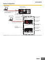
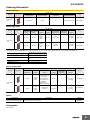
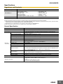
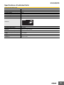
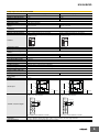
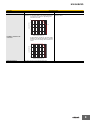
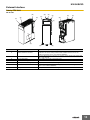
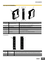
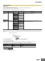
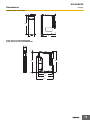
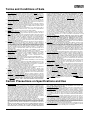
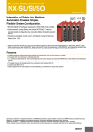
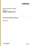
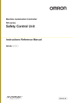
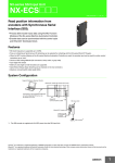
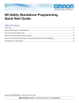
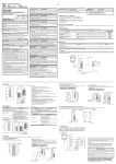
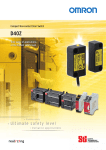
NX-series Safety Control Units
NX-SL/SI/SO
CSM_NX-SL_SI_SO_E_1_1
Integration of Safety into Machine
Automation Enables Simple,
Flexible System Configuration.
• EN ISO13849-1 (PLe/Safety Category4), IEC 61508 (SIL3) certified.
• One connection using Safety over EtherCAT (FSoE) * protocol
enables flexible configuration by mixing the Safety Units with standard
NX I/O.
• Hardware and safety circuits can be configured using the Sysmac
Studio (Ver. 1.07)
* Safety over EtherCAT (FsoE): The open protocol Safety over EtherCAT (abbreviated with FSoE "FailSafe over EtherCAT") defines a safety
related communication layer for EtherCAT. Safety over EtherCAT meets the requirements of IEC 61508 SIL 3 and enables the transfer of safe
and standard information on the same communication system without limitations with regard to transfer speed and cycle time.
Features
• Integrated safety into machine automation possible by connecting with the NX-series EtherCAT Coupler.
• The Safety CPU Unit controls up to 32 Safety I/O Units.
• 4 or 8 points per Safety Input Unit. The 4-point Safety Input Unit can be directly connected with OMRON Non-contact Switches and Singlebeam
Sensors.
• 2 or 4 points per Safety Output Unit. The 2-point Safety Output Unit is characterized by large output breaking current of 2.0 A.
• The Safety Units can be freely allocated in any combination with standard NX I/O.
• Compliant with IEC61131-3
• Safety programs can be standardized and reused efficiently by using POUs for design and operation.
Sysmac is a trademark or registered trademark of OMRON Corporation in Japan and other countries for OMRON factory automation products.
EtherCAT® is a registered trademark of Beckhoff Automation GmbH for their patented technology. Other company names and product names in
this document are the trademarks or registered trademarks of their respective companies.
1
NX-SL/SI/SO
System Configuration
Sysmac Studio
Support Software
EtherCAT master*
NJ-series CPU Unit
Connection to peripheral USB port
or built-in EtherNet/IP port on
NJ-series CPU Unit
Built-in EtherCAT port
Sysmac Studio
Support Software
●EtherCAT Slave Terminal
Communications cable
Ethernet cables
Peripheral USB port.
NX Series
EtherCAT Coupler Unit
NX-ECC201
Safety CPU Unit
NX-SL3300
Safety Input Unit
NX-SID800
Connection to peripheral USB
port on EtherCAT Coupler Unit
NX Units
End Cover
NX Series
EtherCAT Coupler Unit
NX-ECC201
Safety Output Unit
NX-SOD400
Safety Input Unit
NX-SIH400
Safety Output Unit
NX-SOH200
NX Units
End Cover
* OMRON CJ1W-NC@81/@82 Position Control Units cannot be connected to the EtherCAT Slave Terminal even though they support EtherCAT.
2
NX-SL/SI/SO
Ordering Information
Safety CPU Unit
Specifications
Unit type
Appearance
Maximum number of
safety I/O points
Program capacity
Number of safety master
connections
I/O refreshing method
256 points
512KB
32
Free-Run refreshing
Safety CPU
Unit
Model
NX-SL3300
Safety Input Units
Specifications
Unit type
Appearance
Number of
safety input
points
Number of
test output
points
Internal I/O
common
Rated input
voltage
OMRON
special safety
input devices
Number of
safety slave
connections
I/O refreshing
method
4 points
2 points
Sinking
inputs
(PNP)
24 VDC
Can be
connected. *
1
Free-Run
refreshing
NX-SIH400
8 points
2 points
Sinking
inputs
(PNP)
24 VDC
Cannot be
connected.
1
Free-Run
refreshing
NX-SID800
Model
Safety Input
Units
* The following OMRON special safety input devices can be connected directly without a special controller.
For detail of connectable OMRON special safety input devices,refer to NX-series Safety Control Units User's Manual(No.Z930-E1).
.
Model and corresponding PL and
safety category
Type
OMRON Single-beam Safety Sensors
E3ZS and E3FS
OMRON Non-contact Door Switches
D40Z
D40A
OMRON Safety Mats
UM
OMRON Safety Edges
SGE (4-wire connection)
Safety Output Units
Specifications
Unit type
Appearance
Number of safety
output points
Internal I/O
common
Maximum load
current
Rated
voltage
Number of
safety slave
connections
I/O refreshing
method
24 VDC
1
Free-Run
refreshing
NX-SOH200
24 VDC
1
Free-Run
refreshing
NX-SOD400
Model
2.0 A/point, 4.0 A/Unit
at 40°C, and 2.5 A/
Unit at 55°C
2 points
Sourcing
outputs
(PNP)
4 points
Sourcing
outputs
(PNP)
Safety Output
Units
The maximum load
current depends on
the installation
orientation and
ambient temperature.
0.5 A/point and
2.0 A/Unit
Option
Product Name
Unit/Terminal Block Coding Pins
Specification
For 10 Units
(Terminal Block: 30 pins, Unit: 30 pins)
Model
NX-AUX02
Accessories
Not included.
3
NX-SL/SI/SO
Specifications
Regulations and Standards
Certification body
Standards
•
•
•
•
•
•
•
TÜV Rheinland *
UL
EN ISO 13849-1: 2008 + AC: 2009
EN ISO 13849-2: 2012
IEC 61508 parts 1-7: 2010
EN 62061: 2005
EN 61131-2: 2007
EN ISO 13850: 2008
EN 60204-1: 2006 + A1: 2009 + AC: 2010
•
•
•
•
•
•
•
EN 61000-6-2: 2005
EN 61000-6-4: 2007
NFPA 79: 2012
ANSI RIA 15.06-1999
ANSI B11.19-2010
UL1998
IEC 61326-3-1: 2008
cULus: Listed (UL508) and ANSI/ISA 12.12.01
* Certification was received for applications in which OMRON FSoE devices are connected to each other.
The NX-series Safety Control Units allow you to build a safety control system that meets the following standards.
• Requirements for SIL 3 (Safety Integrity Level 3) in IEC 61508, EN 62061, Safety Standard for Safety Instrumented Systems (Functional Safety
of Electrical/Electronic/Programmable Electronic Safety-related Systems)
• Requirements for PLe (Performance Level e) and for safety category 4 in EN ISO13849-1
The NX-series Safety Control Units are also registered for C-Tick and KC compliance.
General Specification
Item
Specification
Enclosure
Mounted in a panel (open)
Grounding method
Ground to 100 Ω or less.
Ambient operating temperature
Operating
environment
0 to 55°C (The upper limit of the ambient operating temperature is restricted by the
installation orientation.)
Ambient operating humidity
10% to 95% (with no condensation or icing)
Atmosphere
Must be free from corrosive gases.
Ambient storage temperature
−25 to 70°C (with no condensation or icing)
Altitude
2,000 m max.
Pollution degree
2 or less: Conforms to JIS B3502 and IEC 61131-2.
Noise immunity
Conforms to IEC 61131-2.
2 kV on power supply line (Conforms to IEC 61000-4-4.)
Insulation class
Class III (SELV)
Overvoltage category
Category II: Conforms to JIS B3502 and IEC 61131-2.
EMC immunity level
Zone B
Conforms to IEC 60068-2-6.
Vibration resistance
5 to 8.4 Hz with 3.5-mm amplitude, 8.4 to 150 Hz, acceleration of 9.8 m/s2, 100 minutes each
in X, Y, and Z directions (10 sweeps of 10 min each = 100 min total)
Conforms to IEC 60068-2-27.
Shock resistance
147 m/s2, 3 times each in X, Y, and Z directions
Insulation resistance
20 MΩ between isolated circuits (at 100 VDC)
Dielectric strength
510 VAC for 1 min between isolated circuits, leakage current: 5 mA max.
Installation method
DIN Track (IEC 60715 TH35-7.5/TH35-15)
Applicable standards
IEC 61508: 2010 SIL 3, EN 62061: 2005 SIL CL3
EN ISO 13849-1, 13849-2: 2008 PL e/Safety Category 4
UL 1998
cULus: Listed UL508, ANSI/ISA 12.12.01
EN 61131-2, C-Tick, KC: KC Registration
4
NX-SL/SI/SO
Specifications of Individual Units
Safety CPU Unit NX-SL3300
Unit name
Safety CPU Unit
Model
NX-SL3300
Maximum number of safety I/O points 256 points
Program capacity
512 KB
Number of safety master connections 32
I/O refreshing method
Free-Run refreshing
External connection terminals
None
FS indicator, VALID indicator, DEBUG indicator, TS indicator, and RUN indicator
Indicators
Dimensions
30 × 100 × 71 mm (W × H × D)
I/O power supply method
Not supplied.
Current capacity of I/O power supply
terminals
No I/O power supply terminals
NX Unit power consumption
0.90 W max.
Current consumption from I/O power
supply
No consumption
Weight
75 g max.
Installation orientation and
restrictions
Installation orientation: 6 possible orientations
Restrictions: None
5
NX-SL/SI/SO
Safety Input Units NX-SIH400/SID800
Unit name
Advanced Safety Input Unit
Safety Input Unit
Model
NX-SIH400
NX-SID800
Number of safety input points
4 points
8 points
Number of test output points
2 points
2 points
Internal I/O common
PNP (sinking inputs)
Rated input voltage
24 VDC (20.4 to 28.8 VDC)
OMRON special safety input
devices
Can be connected.
Number of safety slave
connections
1
I/O refreshing method
Free-Run refreshing
External connection terminals
Screwless clamping terminal block (8 terminals)
Screwless clamping terminal block (16 terminals)
TS indicator, FS indicator, input indicators (yellow), and input
error indicators (red)
TS indicator, FS indicator, input indicators (yellow), and input
error indicators (red)
Cannot be connected.
Indicators
Safety input current
4.5 mA typical
3.0 mA typical
Safety input ON voltage
11 VDC min.
15 VDC min.
Safety input OFF voltage/OFF
current
5 VDC max., 1 mA max.
Test output type
Sourcing outputs (PNP)
Test output load current
25 mA max.
Test output residual voltage
1.2 V max. (Between IOV and all output terminals)
Test output leakage current
0.1 mA max.
Dimensions
12 × 100 × 71 mm (W × H × D)
Isolation method
Photocoupler isolation
Insulation resistance
20 MΩ min. between isolated circuits (at 100 VDC)
Dielectric strength
510 VAC for 1 min between isolated circuits, leakage current: 5 mA max.
I/O power supply method
Power supplied from the NX bus
Current capacity of I/O power
supply terminals
No applicable terminals.
NX Unit power consumption
0.70 W max.
Current consumption from I/O
power supply
20 mA max.
Weight
70 g max.
50 mA max.
0.75 W max.
T0 and T1
Circuit layout
Si0 to Si3
Left-side NX
bus connector
Terminal block
Si0 to Si7
I/O power supply +
I/O power supply +
I/O power supply −
I/O power supply −
Right-side NX
bus connector
Si0 to Si3: Safety input terminals
T0 and T1: Test output terminals
NX-SIH400
Safety
Input Unit
A1
Terminal connection diagram
A8
B1
Internal circuits
Internal circuits
T0 and T1
Terminal block
Left-side NX
bus connector
I/O power supply +
I/O power supply +
I/O power supply −
I/O power supply −
Right-side NX
bus connector
Si0 to Si7: Safety input terminals
T0 and T1: Test output terminals
NX-SID800
Safety
Input Unit
Safety switch
A1
B1
Si0
Si1
Si0
T0
T1
T0
T1
Si2
Si3
T0
T1
Si2
Si3
Si4
Si5
T0
T1
T0
T1
Si6
Si7
T0
T1
B8
Refer to User's manual (Z930-E1) for details.
A8
Safety switch
Si1
B8
Refer to User's manual (Z930-E1) for details.
Installation orientation and
restrictions
Installation orientation: 6 possible orientations.
Restrictions: Maximum ambient temperature is 50ºC for any orientation other than upright installation.
Protective functions
Overvoltage protection circuit and short detection (test outputs)
6
NX-SL/SI/SO
Safety Output Units NX-SOH200/SOD400
Unit name
Safety Output Unit
Model
NX- SOH200
NX-SOD400
Number of safety output points
2 points
4 points
Internal I/O common
PNP (sourcing outputs)
Maximum load current
2.0 A/point
4.0 A/Unit at 40°C
2.5 A/Unit at 55°C
The maximum load current depends on the installation
orientation and ambient temperature
Rated voltage
24 VDC (20.4 to 28.8 VDC)
Number of safety slave
connections
1
I/O refreshing method
Free-Run refreshing
External connection terminals
Screwless clamping terminal block (8 terminals)
0.5 A/point and 2.0 A/Unit
TS indicator, FS indicator, output indicators (yellow), and
output error indicators (red)
TS indicator, FS indicator, output indicators (yellow), and
output error indicators (red)
Indicators
1.2 V max. (Between IOV and all output terminals)
Safety output OFF
residual voltage
2 V max. (Between IOG and all output terminals)
Safety output leakage current
0.1 mA max.
Dimensions
12 × 100 × 71 mm (W × H × D)
Isolation method
Photocoupler isolation
Insulation resistance
20 MΩ min. between isolated circuits (at 100 VDC)
Dielectric strength
510 VAC for 1 min between isolated circuits, leakage current: 5 mA max.
I/O power supply method
Power supplied from the NX bus
Current capacity of I/O power
supply terminals
IOG: 2 A max./terminal
IOG (A3 and B3): 2 A max./terminal
IOG (A7 and B7): 0.5 A max./terminal
NX Unit power consumption
0.70 W max.
0.75 W max.
Current consumption
from I/O power supply
40 mA max.
60 mA max.
Weight
65 g max.
Circuit layout
Left-side NX
bus connector
So0 and So1
Internal circuits
Internal circuits
Safety output ON
residual voltage
Terminal block
IOG
I/O power supply +
I/O power supply +
I/O power supply −
I/O power supply −
So0 and So1: Safety output terminals
IOG: I/O power supply 0 V
Right-side NX
bus connector
Left-side NX
bus connector
I/O power supply +
I/O power supply −
I/O power supply −
A1
A1
B1
A8
B1
So0
So1
IOG
IOG
IOG
NC
NC
So2
So3
NC
NC
IOG
IOG
IOG
L
Terminal connection diagram
L
L
B8
Refer to User's manual (Z930-E1) for details.
Right-side NX
bus connector
So0 to So3: Safety output terminals
IOG: I/O power supply 0 V
NX-SOD400
Safety
Output Unit
So1
Terminal block
IOG
I/O power supply +
NX-SOH200
Safety
Output Unit
So0
So0 to So3
A8
L
B8
Refer to User's manual (Z930-E1) for details.
7
NX-SL/SI/SO
Unit name
Model
Safety Output Unit
NX- SOH200
NX-SOD400
Installation orientation: 6 possible orientations
Restrictions: For upright installation, the ambient temperature
is restricted as shown below depending on the
total Unit load current.
Installation orientation: 6 possible orientations
Restrictions: None
Load current [A]
4
3
2.5A
2
1
0
0
Installation orientation and
restrictions
10
20
30
40
50 55
Ambient temperature [°C]
For all installation orientations other than upright
installation, the ambient temperature is restricted
as shown below according to the total Unit load
current.
Load current [A]
4
3
2
1
0
0
Protective functions
10
20
30
40
50
Ambient temperature [°C]
Overvoltage protection circuit and short detection
8
NX-SL/SI/SO
Version Information
NX-series Safety Control Unit and Sysmac Studio
NX-series Safety Control Unit
NX-SL3300
Sysmac Studio
Version 1.06 or lower
Version 1.07 or higher
Not supported
Supported
NX-series Safety Control Unit and NJ-series CPU Unit
NX-series Safety Control Unit
NX-SL3300
NJ-series CPU Unit
Version 1.05 or lower
Version 1.06 or higher
Not supported
Supported
NX-series Safety Control Unit and NX-series EtherCAT Coupler Unit
NX-series Safety Control Unit
NX-SL3300
NX-series EtherCAT Coupler Unit
Version.1.0 or lower
Version.1.1 or higher
Not supported
Supported
9
NX-SL/SI/SO
External Interface
Safety CPU Unit
NX-SL3300
(D)
(D)
(E)
(C)
(C)
(E)
(E)
(D)
(B)
(A)
(B)
(F)
(G)
(C)
Letter
Item
(C)
Specification
A
Marker attachment locations
The locations where markers are attached. The markers made by OMRON are
installed for the factory setting. Commercially available markers can also be
installed. For details, refer to User's Manual (Z930-E1).
B
NX bus connector
This is the NX-series bus connector. It is used to connect an NX-series Safety I/O
Unit or other NX Unit.
C
Unit hookup guides
These guides are used to connect two Units.
D
DIN Track mounting hooks
These hooks are used to mount the NX Unit to a DIN Track.
E
Protrusions for removing the Unit
The protrusions to hold when removing the Unit.
F
Indicators
The indicators show the current operating status of the NX Unit or signal I/O status.
Refer to User's Manual (Z930-E1).
G
Unit specifications
The specifications of the NX Unit are given here.
10
NX-SL/SI/SO
Safety Input Unit NX-SIH400/SID800
Safety Output Unit NX-SOH200/SOD400
(C) (D) (E)
(B)
(B)
(C)
(F)
(A)
(G)
(C)
(H)
Letter
(E)
(C)
Item
Specification
A
Marker attachment locations
The locations where markers are attached. The markers made by OMRON are
installed for the factory setting. Commercially available markers can also be
installed. For details, refer to User's Manual (Z930-E1).
B
NX bus connector
This is the NX-series bus connector. Connect this connector to another Unit, such as
the NX-series Safety CPU Unit or a Safety I/O Unit.
C
Unit hookup guides
These guides are used to connect two Units.
D
DIN Track mounting hooks
These hooks are used to mount the NX Unit to a DIN Track.
E
Protrusions for removing the Unit
The protrusions to hold when removing the Unit.
F
Indicators
The indicators show the current operating status of the NX Unit or signal I/O status.
Refer to User's Manual (Z930-E1).
G
Terminal block
The terminal block is used to connect to external devices. It connects the safety
outputs. The number of terminals depends on the NX Unit.
H
Unit specifications
The specifications of the NX Unit are given here.
Terminal Blocks
(A)
(B)
A1
B1
A1
B1
A2
B2
A2
B2
A3
B3
A3
B3
A4
B4
A4
B4
A5
B5
A5
B5
A6
B6
A6
B6
A7
B7
A7
B7
A8
B8
A8
B8
(C)
8-terminal type
Letter
(A)
16-terminal type
Item
Terminal number
indications
Specification
The terminal numbers are given by column letters A and B, and row numbers 1 to 8. The combination of
the column and row gives the terminal numbers from A1 to A8 and B1 to B8. The terminal number
indicators are the same regardless of the number of terminals on the terminal block, as shown above.
(B)
Release holes
Insert a flat-blade screwdriver into these holes to connect and remove the wires.
(C)
Terminal holes
The wires are inserted into these holes.
11
NX-SL/SI/SO
Applicable Wires
Using Ferrules
If you use ferrules, attach the twisted wires to them.
Observe the application instructions for your ferrules for the wire stripping length when attaching ferrules.
Always use one-pin ferrules. Do not use two-pin ferrules.
The applicable ferrules, wires, and crimping tool are given in the following table.
Terminal types
Terminals other
than ground
terminals
Manufacturer
Phoenix Contact
Ferrule model
number
Applicable wire
(mm2 (AWG))
AI0,34-8
0.34 (#22)
AI0,5-8
0.5 (#20)
Crimping tool
Phoenix Contact (The figure in parentheses is the applicable wire size.)
CRIMPFOX 6 (0.25 to 6 mm2, AWG24 to 10)
AI0,5-10
AI0,75-8
0.75 (#18)
AI0,75-10
AI1,0-8
1.0 (#18)
AI1,0-10
AI1,5-8
1.5 (#16)
AI1,5-10
Ground terminals
Terminals other
than ground
terminals
Weidmuller
AI2,5-10
2.0 *
H0.14/12
0.14 (#26)
H0.25/12
0.25 (#24)
H0.34/12
0.34 (#22)
H0.5/14
0.5 (#20)
Weidmuller (The figure in parentheses is the applicable wire size.)
PZ6 Roto (0.14 to 6 mm2, AWG 26 to 10)
H0.5/16
H0.75/14
0.75 (#18)
H0.75/16
H1.0/14
1.0 (#18)
H1.0/16
H1.5/14
1.5 (#16)
H1.5/16
* Some AWG 14 wires exceed 2.0 mm2 and cannot be used in the screwless clamping terminal block.
When you use any ferrules other than those in the above table, crimp them to the twisted wires so that the following processed dimensions are
achieved.
Finished Dimensions of Ferrules
8 to 10 mm
1.6 mm max. (except ground terminals)
2.4 mm max. (except ground terminals)
2.0 mm max. (ground terminals)
2.7 mm max. (ground terminals)
Using Twisted Wires/Solid Wires
If you use the twisted wires or the solid wires, the applicable wire range and conductor length (stripping length) are as follows.
Use the twisted wires to connect the ground wire to a ground of 100 Ω or less. Do not use the solid wires.
Terminal types
Applicable wires
Conductor length (stripping length)
Ground terminals
2.0 mm2
9 to 10 mm
Terminals other than ground
terminals
0.08 to 1.5 mm2
AWG28 to 16
8 to 10 mm
Conductor length (stripping length)
12
NX-SL/SI/SO
Dimensions
(Unit/mm)
Safety CPU Unit NX-SL3300
100
30
71
Safety Input Units NX-SIH400/SID800
Safety Output Units NX-SOH200/SOD400
14.1
12.0
1.5
104.5
100
1.5
65.2
71
80.1
13
NX-SL/SI/SO
Related Manuals
Cat. No.
Z930
Z931
Model number
Manual name
Application
Description
NX-SL@@@@
NX-SI@@@@
NX-SO@@@@
NX-series Safety
Control Unit User's
Manual
Learning how to use NX-series Describes the hardware, setup methods, and
Safety Control Units.
functions of the NX-series Safety Control Units.
NX-SL@@@@
NX-series Safety
Control Unit
Instructions
Reference Manual
Learning about the
specifications of instructions
for the Safety CPU Unit.
Describes the instructions for the Safety CPU Unit.
When programming, use this manual together with
the NX-series Safety Control Units User's Manual
(Cat. No. Z930).
14
Terms and Conditions of Sale
1. Offer; Acceptance. These terms and conditions (these "Terms") are deemed
part of all quotes, agreements, purchase orders, acknowledgments, price lists,
catalogs, manuals, brochures and other documents, whether electronic or in
writing, relating to the sale of products or services (collectively, the "Products")
by Omron Electronics LLC and its subsidiary companies (“Omron”). Omron
objects to any terms or conditions proposed in Buyer’s purchase order or other
documents which are inconsistent with, or in addition to, these Terms.
2. Prices; Payment Terms. All prices stated are current, subject to change without notice by Omron. Omron reserves the right to increase or decrease prices
on any unshipped portions of outstanding orders. Payments for Products are
due net 30 days unless otherwise stated in the invoice.
3. Discounts. Cash discounts, if any, will apply only on the net amount of invoices
sent to Buyer after deducting transportation charges, taxes and duties, and will
be allowed only if (i) the invoice is paid according to Omron’s payment terms
and (ii) Buyer has no past due amounts.
4. Interest. Omron, at its option, may charge Buyer 1-1/2% interest per month or
the maximum legal rate, whichever is less, on any balance not paid within the
stated terms.
5. Orders. Omron will accept no order less than $200 net billing.
6. Governmental Approvals. Buyer shall be responsible for, and shall bear all
costs involved in, obtaining any government approvals required for the importation or sale of the Products.
7. Taxes. All taxes, duties and other governmental charges (other than general
real property and income taxes), including any interest or penalties thereon,
imposed directly or indirectly on Omron or required to be collected directly or
indirectly by Omron for the manufacture, production, sale, delivery, importation, consumption or use of the Products sold hereunder (including customs
duties and sales, excise, use, turnover and license taxes) shall be charged to
and remitted by Buyer to Omron.
8. Financial. If the financial position of Buyer at any time becomes unsatisfactory
to Omron, Omron reserves the right to stop shipments or require satisfactory
security or payment in advance. If Buyer fails to make payment or otherwise
comply with these Terms or any related agreement, Omron may (without liability and in addition to other remedies) cancel any unshipped portion of Products sold hereunder and stop any Products in transit until Buyer pays all
amounts, including amounts payable hereunder, whether or not then due,
which are owing to it by Buyer. Buyer shall in any event remain liable for all
unpaid accounts.
9. Cancellation; Etc. Orders are not subject to rescheduling or cancellation
unless Buyer indemnifies Omron against all related costs or expenses.
10. Force Majeure. Omron shall not be liable for any delay or failure in delivery
resulting from causes beyond its control, including earthquakes, fires, floods,
strikes or other labor disputes, shortage of labor or materials, accidents to
machinery, acts of sabotage, riots, delay in or lack of transportation or the
requirements of any government authority.
11. Shipping; Delivery. Unless otherwise expressly agreed in writing by Omron:
a. Shipments shall be by a carrier selected by Omron; Omron will not drop ship
except in “break down” situations.
b. Such carrier shall act as the agent of Buyer and delivery to such carrier shall
constitute delivery to Buyer;
c. All sales and shipments of Products shall be FOB shipping point (unless otherwise stated in writing by Omron), at which point title and risk of loss shall
pass from Omron to Buyer; provided that Omron shall retain a security interest in the Products until the full purchase price is paid;
d. Delivery and shipping dates are estimates only; and
e. Omron will package Products as it deems proper for protection against normal handling and extra charges apply to special conditions.
12. Claims. Any claim by Buyer against Omron for shortage or damage to the
Products occurring before delivery to the carrier must be presented in writing
to Omron within 30 days of receipt of shipment and include the original transportation bill signed by the carrier noting that the carrier received the Products
from Omron in the condition claimed.
13. Warranties. (a) Exclusive Warranty. Omron’s exclusive warranty is that the
Products will be free from defects in materials and workmanship for a period of
twelve months from the date of sale by Omron (or such other period expressed
in writing by Omron). Omron disclaims all other warranties, express or implied.
(b) Limitations. OMRON MAKES NO WARRANTY OR REPRESENTATION,
EXPRESS OR IMPLIED, ABOUT NON-INFRINGEMENT, MERCHANTABIL-
14.
15.
16.
17.
18.
ITY OR FITNESS FOR A PARTICULAR PURPOSE OF THE PRODUCTS.
BUYER ACKNOWLEDGES THAT IT ALONE HAS DETERMINED THAT THE
PRODUCTS WILL SUITABLY MEET THE REQUIREMENTS OF THEIR
INTENDED USE. Omron further disclaims all warranties and responsibility of
any type for claims or expenses based on infringement by the Products or otherwise of any intellectual property right. (c) Buyer Remedy. Omron’s sole obligation hereunder shall be, at Omron’s election, to (i) replace (in the form
originally shipped with Buyer responsible for labor charges for removal or
replacement thereof) the non-complying Product, (ii) repair the non-complying
Product, or (iii) repay or credit Buyer an amount equal to the purchase price of
the non-complying Product; provided that in no event shall Omron be responsible for warranty, repair, indemnity or any other claims or expenses regarding
the Products unless Omron’s analysis confirms that the Products were properly handled, stored, installed and maintained and not subject to contamination, abuse, misuse or inappropriate modification. Return of any Products by
Buyer must be approved in writing by Omron before shipment. Omron Companies shall not be liable for the suitability or unsuitability or the results from the
use of Products in combination with any electrical or electronic components,
circuits, system assemblies or any other materials or substances or environments. Any advice, recommendations or information given orally or in writing,
are not to be construed as an amendment or addition to the above warranty.
See http://www.omron247.com or contact your Omron representative for published information.
Limitation on Liability; Etc. OMRON COMPANIES SHALL NOT BE LIABLE
FOR SPECIAL, INDIRECT, INCIDENTAL, OR CONSEQUENTIAL DAMAGES,
LOSS OF PROFITS OR PRODUCTION OR COMMERCIAL LOSS IN ANY
WAY CONNECTED WITH THE PRODUCTS, WHETHER SUCH CLAIM IS
BASED IN CONTRACT, WARRANTY, NEGLIGENCE OR STRICT LIABILITY.
Further, in no event shall liability of Omron Companies exceed the individual
price of the Product on which liability is asserted.
Indemnities. Buyer shall indemnify and hold harmless Omron Companies and
their employees from and against all liabilities, losses, claims, costs and
expenses (including attorney's fees and expenses) related to any claim, investigation, litigation or proceeding (whether or not Omron is a party) which arises
or is alleged to arise from Buyer's acts or omissions under these Terms or in
any way with respect to the Products. Without limiting the foregoing, Buyer (at
its own expense) shall indemnify and hold harmless Omron and defend or settle any action brought against such Companies to the extent based on a claim
that any Product made to Buyer specifications infringed intellectual property
rights of another party.
Property; Confidentiality. Any intellectual property in the Products is the exclusive property of Omron Companies and Buyer shall not attempt to duplicate it
in any way without the written permission of Omron. Notwithstanding any
charges to Buyer for engineering or tooling, all engineering and tooling shall
remain the exclusive property of Omron. All information and materials supplied
by Omron to Buyer relating to the Products are confidential and proprietary,
and Buyer shall limit distribution thereof to its trusted employees and strictly
prevent disclosure to any third party.
Export Controls. Buyer shall comply with all applicable laws, regulations and
licenses regarding (i) export of products or information; (iii) sale of products to
“forbidden” or other proscribed persons; and (ii) disclosure to non-citizens of
regulated technology or information.
Miscellaneous. (a) Waiver. No failure or delay by Omron in exercising any right
and no course of dealing between Buyer and Omron shall operate as a waiver
of rights by Omron. (b) Assignment. Buyer may not assign its rights hereunder
without Omron's written consent. (c) Law. These Terms are governed by the
law of the jurisdiction of the home office of the Omron company from which
Buyer is purchasing the Products (without regard to conflict of law principles). (d) Amendment. These Terms constitute the entire agreement between
Buyer and Omron relating to the Products, and no provision may be changed
or waived unless in writing signed by the parties. (e) Severability. If any provision hereof is rendered ineffective or invalid, such provision shall not invalidate
any other provision. (f) Setoff. Buyer shall have no right to set off any amounts
against the amount owing in respect of this invoice. (g) Definitions. As used
herein, “including” means “including without limitation”; and “Omron Companies” (or similar words) mean Omron Corporation and any direct or indirect
subsidiary or affiliate thereof.
Certain Precautions on Specifications and Use
1. Suitability of Use. Omron Companies shall not be responsible for conformity
with any standards, codes or regulations which apply to the combination of the
Product in the Buyer’s application or use of the Product. At Buyer’s request,
Omron will provide applicable third party certification documents identifying
ratings and limitations of use which apply to the Product. This information by
itself is not sufficient for a complete determination of the suitability of the Product in combination with the end product, machine, system, or other application
or use. Buyer shall be solely responsible for determining appropriateness of
the particular Product with respect to Buyer’s application, product or system.
Buyer shall take application responsibility in all cases but the following is a
non-exhaustive list of applications for which particular attention must be given:
(i) Outdoor use, uses involving potential chemical contamination or electrical
interference, or conditions or uses not described in this document.
(ii) Use in consumer products or any use in significant quantities.
(iii) Energy control systems, combustion systems, railroad systems, aviation
systems, medical equipment, amusement machines, vehicles, safety equipment, and installations subject to separate industry or government regulations.
(iv) Systems, machines and equipment that could present a risk to life or property. Please know and observe all prohibitions of use applicable to this Product.
NEVER USE THE PRODUCT FOR AN APPLICATION INVOLVING SERIOUS
RISK TO LIFE OR PROPERTY OR IN LARGE QUANTITIES WITHOUT
ENSURING THAT THE SYSTEM AS A WHOLE HAS BEEN DESIGNED TO
2.
3.
4.
5.
ADDRESS THE RISKS, AND THAT THE OMRON’S PRODUCT IS PROPERLY RATED AND INSTALLED FOR THE INTENDED USE WITHIN THE
OVERALL EQUIPMENT OR SYSTEM.
Programmable Products. Omron Companies shall not be responsible for the
user’s programming of a programmable Product, or any consequence thereof.
Performance Data. Data presented in Omron Company websites, catalogs
and other materials is provided as a guide for the user in determining suitability and does not constitute a warranty. It may represent the result of Omron’s
test conditions, and the user must correlate it to actual application requirements. Actual performance is subject to the Omron’s Warranty and Limitations
of Liability.
Change in Specifications. Product specifications and accessories may be
changed at any time based on improvements and other reasons. It is our practice to change part numbers when published ratings or features are changed,
or when significant construction changes are made. However, some specifications of the Product may be changed without any notice. When in doubt, special part numbers may be assigned to fix or establish key specifications for
your application. Please consult with your Omron’s representative at any time
to confirm actual specifications of purchased Product.
Errors and Omissions. Information presented by Omron Companies has been
checked and is believed to be accurate; however, no responsibility is assumed
for clerical, typographical or proofreading errors or omissions.
OMRON INDUSTRIAL AUTOMATION • THE AMERICAS HEADQUARTERS
Schaumburg, IL USA • 847.843.7900 • 800.556.6766 • www.omron247.com
OMRON CANADA, INC. • HEAD OFFICE
Toronto, ON, Canada • 416.286.6465 • 866.986.6766 • www.omron247.com
OMRON ARGENTINA • SALES OFFICE
Cono Sur • 54.11.4783.5300
OMRON ELECTRONICS DE MEXICO • HEAD OFFICE
México DF • 52.55.59.01.43.00 • 001.800.556.6766 • [email protected]
OMRON CHILE • SALES OFFICE
Santiago • 56.9.9917.3920
OMRON ELECTRONICS DE MEXICO • SALES OFFICE
Apodaca, N.L. • 52.81.11.56.99.20 • 001.800.556.6766 • [email protected]
OTHER OMRON LATIN AMERICA SALES
54.11.4783.5300
OMRON ELETRÔNICA DO BRASIL LTDA • HEAD OFFICE
São Paulo, SP, Brasil • 55.11.2101.6300 • www.omron.com.br
OMRON EUROpE B.V. • Wegalaan 67-69, NL-2132 JD, Hoofddorp, The Netherlands. • Tel: +31 (0) 23 568 13 00
Fax: +31 (0) 23 568 13 88 • www.industrial.omron.eu
Cat. No. &60B1;6/B6,B62B(BB
0/13
Note: Specifications are subject to change.
© 2013 Omron Electronics LLC
Printed in U.S.A.