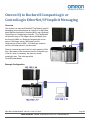
1
NX Safety Standalone Programming
Quick Start Guide
Table of Contents
Quick Links .............................................................................................................................................................................. 2
Convert NJ/NX Program to NX Standalone............................................................................................................................. 3
First Time Users Quick Start Guide ......................................................................................................................................... 9
Differences Between NJ/NX and NX Standalone .................................................................................................................. 23
Omron NJ to Rockwell CompactLogic or ControlLogix EtherNet/IP Implicit Messaging ...................................................... 26
EtherNet/IP Error Code Decoder ........................................................................................................................................... 35
QSG-NX-S-STANDALONE - Version 3.2 Feb. 27, 2015
OMRON AUTOMATION & SAFETY • © 2015 Omron Electronics LLC • www.omron247.com
Quick Links
Manuals
http://industrial.omron.us/en/products/catalogue/automation_systems/integrated_safety/nx_safety_distribut
ed/default.html
Scroll to the tab section, select “Download”, select “Manuals”, download pdf file under the EN column.
Sysmac Studio Software and Registration
http://industrial.omron.us/en/products/software-registration-downloads
Videos
QSG-NX-S-STANDALONE - Version 3.2 Feb. 27, 2015
OMRON AUTOMATION & SAFETY • © 2015 Omron Electronics LLC • www.omron247.com
Page 2
Convert NJ/NX Program to NX Standalone
December 2014, Sysmac Studio version 1.11
Hardware
Replace the coupler, NX CPU and SIH400 input modules.
Open up a new project
1.) This is available with Sysmac Studio version 1.10 and
higher. (Released Sept. 2014)
Category: Slave Terminal
Device: EtherNet/IP Coupler
Hardware set-up without actual hardware
1.) Use schematics or take a snap shot of the original equipment. If you have multiple screens,
you can open Sysmac Studios up for both projects.
2.) In this case, the SIH400 safety input module is version 1.0. The Safety stand-alone CPU
requires at least a 1.1 version SIH400 module. This will need to be upgraded.
(To change: right click on module -> change model -> select the new model -> ok)
Node Configuration
3.) From the CPU drop down list, select “new_SafetyCPU0”
QSG-NX-S-STANDALONE - Version 3.2 Feb. 27, 2015
OMRON AUTOMATION & SAFETY • © 2015 Omron Electronics LLC • www.omron247.com
Page 3
4.) Multiview Explorer -> Configurations and Setup -> Communications -> Safety -> Safety I/O ->
EIP/Unit2: (Module type) (Instance) -> Parameter -> click on the white X in the upper right
corner to view all nodes.
5.) Copy and paste the comments from the NJ/NX
program into the NX standalone program. You
need to do one at a time, and you can use the cut
and paste function on your PC. (Note: Copy and
pasting the comments is an option.)
6.) From the toolbox, drag and drop the device type
Global Variables
7.) Copy and paste the global variables.
8.) Mutiview Explorer -> Programming -> Data -> Global Variables
9.) In NJ/NX Program -> Right click -> select all – right click -> copy
10.) In the NX Stand Alone project -> Global Variable -> right click -> paste
11.) (Optional) If you have the original list with the variable names and if they are inputs or
outputs, skip these optional steps.
Easy way to enter the standard variables (BOOL) into the exposed variable list.) Copy and
Paste the global variable list into Excel.
12.) (Optional) In Excel, click on upper left box to select the entire table -> “Data” in the top menu
-> Sort -> column B. (The BOOL variables are at the top of the list.)
13.) (Optional) -> add a column to the Excel spreadsheet.
14.) (Optional) Open up programs in Sysmac Studio to determine if they are inputs or outputs.
15.) Hint: If you can’t find them easily, Cntr + F, and enter the variable name in the “search what”
field, select the “search and replace results” tab at the bottom of the screen, then double click
on one of the search results.
Expose Variables on Safety Side
16.) Multiview Explorer -> Configurations and Setup ->
Communications -> Standard -> Slave I/O -> Exposed
Variable
17.) Right click on “Name” field -> create new -> start typing
name (pull down list will appear so you can select the full
name)
18.) Change the “In / Out” as needed.
19.) Repeat the steps for all of the standard variable names.
QSG-NX-S-STANDALONE - Version 3.2 Feb. 27, 2015
OMRON AUTOMATION & SAFETY • © 2015 Omron Electronics LLC • www.omron247.com
Page 4
Assign Variables Location on Standard Side
20.) Multiview Explorer -> Configurations and
Setup -> Communications -> Standard ->
Standard I/O
21.) Manually assign the device and linked
port. (Hint: If you have multiple screens
with a copy of the original and new
programs open, look at the I/O map of the
original program. NJ controller ->
Configurations and Setup -> I/O Map)
I/O Map
22.) Multiview explorer -> Configurations and Setup -> I/O Map
Notice: Depending on the versions of NX CPUs you were using, the comments from the original NJ/NX program may be
ones that were manually created. The NX Standalone program will reuse the comments created in the nodes in the I/O map.
NJ/NX
NX Standalone
23.) Most efficient way to enter the variable names is to use the pull down list. Cut and Pasting
the entire list did not transfer all of them correctly.
QSG-NX-S-STANDALONE - Version 3.2 Feb. 27, 2015
OMRON AUTOMATION & SAFETY • © 2015 Omron Electronics LLC • www.omron247.com
Page 5
NX (Safety) Programs
24.) In the NX Standalone program, create the same program names as the NJ/NX program.
25.) Copy the “Internals from the program” in the NJ/NX program.
26.) Paste it into the NX Standalone program.
If you have a blank first variable, right click and delete.
27.) Repeat steps 14 and 15 for the External variables in the program
28.) In the NJ/NX program, Select the left column to highlight, then scroll down and hold the shift
key on the computer keyboard while selecting the last line. Right click -> copy.
QSG-NX-S-STANDALONE - Version 3.2 Feb. 27, 2015
OMRON AUTOMATION & SAFETY • © 2015 Omron Electronics LLC • www.omron247.com
Page 6
29.) In the NX Standalone program, open up the program, click on the left column to highlight the
line, right click and paste. Scroll down to the bottom and delete the last line if it is empty.
30.) Repeat these steps for all of the programs.
Build
31.) Project -> Build controller
Download
1.) Go Online.
2.) Select “new_SlaveTerminal_0” (or the name it was changed to for the coupler )from the device
pulldown menu.
3.) Configurations and Setup -> EtherNet/IP -> NX-EIC202
4.) Double click on NX-EIC202
QSG-NX-S-STANDALONE - Version 3.2 Feb. 27, 2015
OMRON AUTOMATION & SAFETY • © 2015 Omron Electronics LLC • www.omron247.com
Page 7
5.) Right click on “EIC202” -> Coupler Connection (USB) -> Transfer to Coupler
6.) Select “new_SafetyCPU0” (or the name it was changed to for the Safety CPU )from the device
pulldown menu.
7.) Controller -> Mode -> Program
8.) Controller -> Mode -> Debug
9.) Controller -> Safety Validation
10.)
Controller -> Mode -> Run
Program for current sales demo is “Sales Demo Converted to Stand Alone.smc2”.
QSG-NX-S-STANDALONE - Version 3.2 Feb. 27, 2015
OMRON AUTOMATION & SAFETY • © 2015 Omron Electronics LLC • www.omron247.com
Page 8
First Time Users Quick Start Guide
Open up a new project (Video)
1.) Double click on the Sysmac Studio icon.
2.) Select “Yes” when the ‘’Do you want to allow the following program from an unknown publisher
to make changes to this computer?”
3.) Select “License”, enter the license number, and select “Register License”.
The software has a 30-day limited trial period. If you do not yet have your license, skip this
step. Once the license is registered, the Sysmac Studio version, installed products, user
name, company name, license and license type will be displayed.
(Note: not all information is shown for the license information.)
4.) Select “New Project”.
QSG-NX-S-STANDALONE - Version 3.2 Feb. 27, 2015
OMRON AUTOMATION & SAFETY • © 2015 Omron Electronics LLC • www.omron247.com
Page 9
5.) Enter the Project Name. Author and Comment fields are optional.
6.) Under “Type”, select “Standard Project”.
7.) Under “Select Device” section, for category select “Slave Terminal”. Verify “EtherNet/IP
Coupler” automatically appears for “Device”.
8.) Select “Create”.
Workspace Overview
Menu and icons
Toolbox
MultiView
Explorer
Workspace
Errors and Monitoring
Status
QSG-NX-S-STANDALONE - Version 3.2 Feb. 27, 2015
OMRON AUTOMATION & SAFETY • © 2015 Omron Electronics LLC • www.omron247.com
Page 10
Each section can be dragged to change its size by moving the mouse over the black solid bar
that separates each section, hold down the left mouse button and drag the screen edge.
Tabs are used to switch between multiple screens opened with the same section.
Manually Add Hardware (Video)
11.)
In the Multiview Explorer section, verify the CPU listed in the pull down box is
“new_SlaveTerminal_0.”
12.)
To change rename the CPU, right click on the CPU icon and select “rename” from the
list. Note: the list also includes the option to add device and delete.
QSG-NX-S-STANDALONE - Version 3.2 Feb. 27, 2015
OMRON AUTOMATION & SAFETY • © 2015 Omron Electronics LLC • www.omron247.com
Page 11
13.)
In the Multiview Explorer, left click on the mouse for “Configuration and Setup”. This will
allow more options to be viewed and selected.
14.)
Left mouse click on the arrow next to EtherNet/IP.
15.)
Double click on “NX-EIC202 : Offline
16.)
The screen will look similar. Some of the areas may need to be adjusted for better
viewing.
QSG-NX-S-STANDALONE - Version 3.2 Feb. 27, 2015
OMRON AUTOMATION & SAFETY • © 2015 Omron Electronics LLC • www.omron247.com
Page 12
Hardware set-up with actual hardware installed and connected
17.)
Right click on the master coupler “NX-EIC202 Master.” You the name was change
earlier, it may have that name here instead.
18.)
Connect the Ethernet cable from the computer to the coupler.
19.)
Right click on the master coupler “NX-EIC202 Master”, select “Coupler Connection
(USB)” at the bottom of the pulldown list, then select “Online”
20.)
Right click again on the master coupler “NX-EIC202 Master”, the select “Compare and
merge with actual configuration.”
21.)
Select “Apply actual network configuration” and then “Okay.” Close the box. Here is an
example of a configuration.
Note: END01 is the end cap. Sysmac Studio automatically added it to the configuration. The
actual piece should have come with the coupler.
QSG-NX-S-STANDALONE - Version 3.2 Feb. 27, 2015
OMRON AUTOMATION & SAFETY • © 2015 Omron Electronics LLC • www.omron247.com
Page 13
Hardware set-up without actual hardware
22.)
Under the Group section in the Toolbox, scroll down until you see”Safety CPU Device.”
23.)
Under the “Input Keyword” section, left click on(and hold) the “NX-SL330 Ver1.1” Safety
CPU while dragging this next to the master coupler “NX-EIC202 Master.” Release the left mouse
button when the orange bar appears.
24.)
In the “group” section, scroll to the I/O modules being used. Follow the previous step
for the I/O modules. Example shows the SID800 input module. (Added orange bar so you can
see what it looks like before Sysmac Studio adds the module.)
25.)
Up to 32 safety input and output modules can be added. Up to 63 total (safety and
standard input and output modules can be added. Symbols will appear below the module if
incorrect version of modules is selected, power unit is exceeded, and too many modules have
been added.
26.)
Right click on the module for options such as delete, copy, cut, paste, undo, change
model, edit unit operation settings, etc.
QSG-NX-S-STANDALONE - Version 3.2 Feb. 27, 2015
OMRON AUTOMATION & SAFETY • © 2015 Omron Electronics LLC • www.omron247.com
Page 14
Node Configuration (Video)
27.)
From the CPU drop down list, select “new_SafetyCPU0”. Notice that the icon for the
controller changed.
28.)
In Multiview Explorer -> Configurations and Setup -> Communications -> Safety ->
Safety I/O -> EIP/Unit2: (Module type) (Instance) -> double click on “Parameter”.
29.)
In the toolbox, open up the type of safety device that will be wired
into I/O module. The bottom area has a description of the device.
30.)
If you don’t know what device configuration is needed, contact
your Omron distributor or Omron Account Manager for a copy of the
“NX Safety Selection Setup and Programming Guide”.
31.)
Note: Click on the white X in the upper right corner to view all of
the nodes.
32.)
Drag and drop the device type from the tool box and attach it to the node. The node
stubs will turn green when it can be dropped.
QSG-NX-S-STANDALONE - Version 3.2 Feb. 27, 2015
OMRON AUTOMATION & SAFETY • © 2015 Omron Electronics LLC • www.omron247.com
Page 15
33.)
If needed, change the test pulses and discrepancy time.
34.)
Optional: Enter a comment.
Note: This comment will be reused elsewhere in the program.
35.)
Complete this for the rest of the devices.
Global Variables (Video)
36.) Some people create their initial global variable list in Excel.
Note: Variable names have a list of rules, such as no spaces, not starting with a number, etc.)
37.)
Mutiview Explorer -> Programming -> Data -> double click on “Global Variables.”
38.) Either double click or right click on “Empty. Click here to add items,” then select “create
new”. Type the variable name.
39.) If the variable list was created in Excel, create a dummy global variable. Right click on the
dummy variable and select “copy”.
40.) In the Excel spreadsheet, paste the dummy variable into a blank row.
QSG-NX-S-STANDALONE - Version 3.2 Feb. 27, 2015
OMRON AUTOMATION & SAFETY • © 2015 Omron Electronics LLC • www.omron247.com
Page 16
41.) Copy the three new fields the dummy variable added and paste into the other global
variables.
42.) Copy the rest of the global variables.
43.) In Sysmac Studio under “name, right click and select “paste”.
44.) Delete the Dummy variable.
45.) (Optional) If you have the original list with the variable names and if they are inputs or
outputs, skip these optional steps.
46.) Note: Safety variable have a data type of “SAFEBOOL”. Non safety variable have a data
type such as “BOOL”.
QSG-NX-S-STANDALONE - Version 3.2 Feb. 27, 2015
OMRON AUTOMATION & SAFETY • © 2015 Omron Electronics LLC • www.omron247.com
Page 17
Expose Variables on the Safety Side (Video)
47.) Multiview Explorer -> Configurations and Setup ->
Communications -> Standard -> Slave I/O -> Exposed
Variable
48.) Right click on “Name” field -> create new -> start typing
name (pull down list will appear so you can select the full
name)
49.) Change the “In / Out” as needed.
50.) Repeat the steps for all of the standard variable names.
Assign Variables Location on Standard Side
51.) Multiview Explorer -> Configurations and
Setup -> Communications -> Standard ->
Standard I/O
52.) Manually assign the device and linked
port. (Hint: If you have multiple screens
with a copy of the original and new
programs open, look at the I/O map of the
original program. NJ controller ->
Configurations and Setup -> I/O Map)
I/O Map (Video)
53.) Multiview explorer -> Configurations and Setup -> I/O Map
Note: The NX Stand Alone program will reuse the comments created in the nodes in the I/O map.
54.) Most efficient way to enter the variable names is to use the pull down list, start typing, and
select the variable name. It will only list variable already listed in the global variable list.
QSG-NX-S-STANDALONE - Version 3.2 Feb. 27, 2015
OMRON AUTOMATION & SAFETY • © 2015 Omron Electronics LLC • www.omron247.com
Page 18
55.) Option for machine where I/O modules could be shut down for maintenance with zones, but
still allow the machine in other zones to run. It is recommended to set this up. Enter a
variable name for each of the “Safety Connection Status.”
NX (Safety) Program
Video - Insert New Line (network)
Video - Create a basic program
56.) Multiview Explorer -> Programming -> POUs -> Programs -> Program0.
Note: To change the name of program0, right click and select “rename”. Type in the new
name and press “enter”.
57.) Double click on the program name.
58.) In the toolbar (on the right side), open up the “Boolean Operator” section by clicking on the
arrow.
QSG-NX-S-STANDALONE - Version 3.2 Feb. 27, 2015
OMRON AUTOMATION & SAFETY • © 2015 Omron Electronics LLC • www.omron247.com
Page 19
59.) If you only have 2 safety I/O modules, drag and drop AND(2) to the center of the screen until
a green box that says “Start Here” appears. Drop it on the green box. If you have more than
2 I/O modules, select AND(3).
60.) The AND function block can have up to 8 inputs. To add more inputs, right click on the
function block and select “Add Input”.
61.) Just left of the dash mark on the input side (left), left click. Start to type the name of the
variable. A list of the variable will appear that you can choose from. Add all of the “Safety
Connection Status” variables added in the I/O map earlier.
Note: Example on the right is from another program.
62.) To the far left of the row, right click and select “Insert Network Below” to add another row.
QSG-NX-S-STANDALONE - Version 3.2 Feb. 27, 2015
OMRON AUTOMATION & SAFETY • © 2015 Omron Electronics LLC • www.omron247.com
Page 20
63.) In the toolbar (on the right side), open up the “Safety Function blocks” section by clicking on
the arrow. This is a list of the function blocks needed for the safety devices.
64.) Left click on a function block and drag it to the left so it over the “Start here” green box.
65.) Enter a name for the safety function block. (Left click and type when ??? turn into blanks and
the … button, then enter.)
66.) The activate inputs verifies the module is active. If multiple I/O modules were used, this
would use the same variable defines as the output of the AND function block.
In this example “SID800_Unit2_OK” could be used. If the Safety Connection status variable was
not defined in the I/O map, “true” would be used.
67.) Enter the inputs variables on the left side of the function block, and the output variable on the
right side. In this example, more logic will be added to the output variable. If the logic string
was long or needed in multiple places, a variable could be defined. See the manual or quick
start guides for more programming details.
68.) To add another function block, drag it until the green diamond appears on the S_EStopOut
output.
QSG-NX-S-STANDALONE - Version 3.2 Feb. 27, 2015
OMRON AUTOMATION & SAFETY • © 2015 Omron Electronics LLC • www.omron247.com
Page 21
Build (Video)
69.)
Project -> Build controller (or F8).
70.)
Click on the “Build” tab to see the errors and warnings.
Download (Video Coupler) (Video Safety)
71.)
Go Online.
72.)
Select “new_SlaveTerminal_0” (or the name it was changed to for the coupler) from the
device pulldown menu.
73.)
Configurations and Setup -> EtherNet/IP -> NX-EIC202
74.)
Double click on NX-EIC202
75.)
Right click on “EIC202” -> Coupler Connection (USB) -> Transfer to Coupler
76.)
Select “new_SafetyCPU0” (or the name it was changed to for the Safety CPU )from the
device pulldown menu.
77.)
78.)
79.)
80.)
Controller -> Mode -> Program
Controller -> Mode -> Debug
Controller -> Safety Validation
Controller -> Mode -> Run
QSG-NX-S-STANDALONE - Version 3.2 Feb. 27, 2015
OMRON AUTOMATION & SAFETY • © 2015 Omron Electronics LLC • www.omron247.com
Page 22
Differences Between NJ/NX and NX Standalone
Creating a New Project
When creating a new project, under “Select Device” section, for category select “Slave Terminal”. Verify
“EtherNet/IP Coupler” automatically appears for “Device”.
Online
Difference #1 No choice with communication type (Ethernet or USB) when going online.
Difference #2 No way to go online from menu bar of the coupler.
(However, really easy to log on from the menu bar of the Safety CPU.)
Only able to go online with the USB cable.
CPU Pulldown List
The CPU listed in the pull down box is “new_SlaveTerminal_0.”
Hardware Configuration
New naming is EtherNet/IP and it automatically has the coupler.
The toolbox does not list couplers.
It only shows the NX-SL3300 V1.1.
(No NX-SL3500)
It will automatically select the SIH400 V1.1 module.
QSG-NX-S-STANDALONE - Version 3.2 Feb. 27, 2015
OMRON AUTOMATION & SAFETY • © 2015 Omron Electronics LLC • www.omron247.com
Page 23
Assign Variables Location on Standard Side
1.) Multiview Explorer -> Configurations and Setup
-> Communications -> Standard -> Standard I/O
2.) Manually assign the device and linked port.
(Hint: If you have multiple screens with a copy
of the original and new programs open, look at
the I/O map of the original program. NJ
controller -> Configurations and Setup -> I/O
Map)
Standard I/O Map
It is located under the safety CPU.
Insert Additional Coupler
Menu bar -> Insert -> Slave Terminal -> Ethernet/IP coupler
Ethernet/IP Coupler
Additional couplers can be added, but they will not have everything
needed to map I/O, label variable or do programming unless an NX
CPU is added.
QSG-NX-S-STANDALONE - Version 3.2 Feb. 27, 2015
OMRON AUTOMATION & SAFETY • © 2015 Omron Electronics LLC • www.omron247.com
Page 24
Can I expand I/O on the network with additional couplers?
No. (Page 41 NX-series Safety Control Unit User’s Manual Z930)
Coupler unit is limited to the EtherNET/IP Slave Terminal at the connection.
You can add Safety CPU to each coupler with safety. (page 45)
Safety I/O
Node is listed as EIP instead of a node setting
NX Stand Alone Quick Start Guide - Version 3.2 Feb. 27, 2015
Page 25
Omron NJ to Rockwell CompactLogic or
ControlLogix EtherNet/IP Implicit Messaging
Overview
This section is to setup an EtherNet/IP Tag Datalink (Implicit
Messaging) connection between an Omron NJ or NX Standalone Machine Automation Controller (MAC) and a Rockwell
ControlLogix or CompactLogix controller. This Tag Datalink
will share an array of 100 Integer values (200 Bytes) from
the Omron NJ MAC to a Rockwell CompactLogix and an
array of 100 Integer values (200 Bytes) from the
CompactLogix to the NJ MAC. A ControlLogix would be
similar to the steps shown in this document.
There is a second tag used in the NJ, which maps the 32 bit
Run / Idle header in the connection from the CompactLogix
to the NJ, which is necessary, but does not contain
meaningful data. This is the tag called
CLtoNJRunIdleHeader.
Example Configuration
QSG-NX-S-STANDALONE - Version 3.2 Feb. 27, 2015
OMRON AUTOMATION & SAFETY • © 2015 Omron Electronics LLC • www.omron247.com
Page 28
NJ Configuration
1. In Sysmac Studio, configure the Sysmac NJ tags as shown in the Global Variables.
2. Synchronize the project with the NJ controller to transfer the Tags to the NJ.
3. In Sysmac Studio, export the Tags to the Network Configurator for EtherNet/IP.
4. Save the .csv file that contains the tags. This will be imported in a later step.
5. In the Network Configurator for EtherNet/IP, add
an NJ to the network diagram. Select the
correct model and Revision. Rev 1 = NJ
firmware 1.00, 1.01, or 1.02. Rev 2 = NJ
firmware 1.03 or higher.
QSG-NX-S-STANDALONE - Version 3.2 Feb. 27, 2015
OMRON AUTOMATION & SAFETY • © 2015 Omron Electronics LLC • www.omron247.com
Page 27
6. Right click on the NJ in the network diagram, and select ‘Change Node Address’. Enter the
IP Address of the NJ, and click ‘OK’.
7. Double click on the NJ CPU in the network diagram.
8. Click on the ‘Tag Sets’ tab, and click ‘To / From File’, and select ‘Import from File’.
9. Browse for the .csv file created earlier, select it,
and click ‘Open’.
10. When “All of the network variables will be imported” dialog box appears, click ‘Yes’.
QSG-NX-S-STANDALONE - Version 3.2 Feb. 27, 2015
OMRON AUTOMATION & SAFETY • © 2015 Omron Electronics LLC • www.omron247.com
Page 28
11. When “New Tag sets will be created
automatically from the Tags that will be
imported” click ‘Yes’.
12. On the ‘In- Consume‘ tab,
select the Tag Set named
‘CLtoNJRunIdleHeader’, and
click ‘Delete’.
13. When the “Selected Tags set and Tags that the Tag
sets have all been deleted” dialog box appears, click
‘No’.
14. On the ‘In- Consume‘ tab, select
the Tag Set named ‘CLtoNJ’, and
click ‘Edit’.
15. Select the Tag named
‘CLtoNJRunIdleHeader’ on the
right, and click the 2 left pointing
arrows to add this tag to the Tag Set
on the left.
QSG-NX-S-STANDALONE - Version 3.2 Feb. 27, 2015
OMRON AUTOMATION & SAFETY • © 2015 Omron Electronics LLC • www.omron247.com
Page 29
16. In the Tag Set on the left, select the
Tag named ‘CLtoNJRunIdleHeader’,
and click the Up Arrow to move the tag
to the top of the list.
17. Verify that the CLtoNJRunIDleHeader is
now at the top of the list, then click
‘Advanced’.
18. Select the ‘Manual’ radio button, and enter a value of 100
for the Assembly Number. Click ‘OK’.
19. Click ‘OK’ to complete the edit of the Tag Set.
QSG-NX-S-STANDALONE - Version 3.2 Feb. 27, 2015
OMRON AUTOMATION & SAFETY • © 2015 Omron Electronics LLC • www.omron247.com
Page 30
20. Click on the ‘Out – Produce’ tab, and
select ‘Edit’.
21. Click ‘Advanced’.
22. Select the ‘Manual’ radio button, and enter a value of 110 for the
Assembly Number. Click ‘OK’.
23. Click ‘OK’ to complete the edit of the Tag Set.
24. Click ‘OK’ to complete the network configuration of the NJ.
25. The network configuration has been setup, but still need to be downloaded to the NJ. To
connect to the network, click ‘Options’ / ‘Select Interface’ menus. Choose ‘Ethernet I/F’.
QSG-NX-S-STANDALONE - Version 3.2 Feb. 27, 2015
OMRON AUTOMATION & SAFETY • © 2015 Omron Electronics LLC • www.omron247.com
Page 31
26. Click on the ‘Network’ / ‘Connect’ menus to
connect to the network.
27. Click ‘OK’ to connect .
28. Click ‘OK’ to select ‘Use the existing network’.
29. Download the EtherNet/IP settings to the
NJ by right clicking on the NJ in the
network diagram, and select ‘Parameter’ /
‘Download’.
30. When “Downloading parameters to selected devices will
start”, dialog box appears, click ‘Yes’.
31. If the NJ is not in program mode, you will
get the option to change modes, or
download with the NJ in the current mode.
Click ‘Download with Current mode’.
32. When “Download of device parameters was completed”
dialog box appears, the NJ is ready to accept a connection
from a CompactLogix. Click ‘OK’.
QSG-NX-S-STANDALONE - Version 3.2 Feb. 27, 2015
OMRON AUTOMATION & SAFETY • © 2015 Omron Electronics LLC • www.omron247.com
Page 32
CompactLogix Configuration
1. Open an existing project file or create a new project file for the CompactLogix in RSLogix
5000.
2. Configure the IP address of the CompactLogix as 192.168.1.77 using RSLogix 5000 (as an
example IP Address).
3. In RSLogix 5000, right click on the Ethernet module in the
CompactLogix, and click ‘New Module’.
4. In the ‘Communications’ group, select
‘ETHERNET-MODULE Generic
Ethernet Module’, and click ‘OK’.
QSG-NX-S-STANDALONE - Version 3.2 Feb. 27, 2015
OMRON AUTOMATION & SAFETY • © 2015 Omron Electronics LLC • www.omron247.com
Page 33
5. Configure the connection as
shown, and click OK.
6. Configure the RPI for 10 ms, and click OK.
Tags will have been created automatically for the OmronNJ connection as shown below.
7. Download the project to the CompactLogix processor using RSLogix 5000.
8. Using RSLogix 5000 and Sysmac Studio to set data and monitor the data in the 2 controllers,
verify the operation of the EtherNet/IP Tag Datalink.
Data from NJ to CompactLogix
Data from CompactLogix to NJ
QSG-NX-S-STANDALONE - Version 3.2 Feb. 27, 2015
OMRON AUTOMATION & SAFETY • © 2015 Omron Electronics LLC • www.omron247.com
Page 34
EtherNet/IP Error Code Decoder
1.) Go online with the Network Configurator.
2.) Upload from the PLC / MAC if the configuration in the EIP card is different from the Network
Configurator.
3.) Right click the PLC / MAC and select 'Monitor'.
4.) Go to the 'Connection' tab. The error code is shown in 'Status'.
QSG-NX-S-STANDALONE - Version 3.2 Feb. 27, 2015
OMRON AUTOMATION & SAFETY • © 2015 Omron Electronics LLC • www.omron247.com
Page 35
5.) Use the list to find the status code and description of the failure.
01:0100
01:0103
01:0106
01:0107
01:0108
01:0109
01:0110
01:0111
01:0113
01:0114
01:0115
01:0116
01:0117
01:0118
01:0119
01:011A
01:011B
01:011C
01:011D
01:011E
01:011F
01:0120
01:0121
01:0122
01:0123
01:0124
01:0125
01:0126
01:0127
01:0128
01:0129
01:012A
01:012B
01:012C
01:012D
01:012E
01:012F
01:0130
01:0131
01:0132
01:0133
01:0203
01:0204
01:0205
01:0206
Connection in use or duplicate forward open
Transport class and trigger combination not supported
Ownership Conflict
Target connection not found
Invalid network connection parameter
Invalid connection size
Target for connection not configured
RPI not supported
Out of connections
Vendor ID or Product Code mismatch
Product Type Mismatch
Revision Mismatch
Invalid Produced or Consumed application path
This could be Tag Names that do not match in the PLC
Invalid or inconsistent configuration application path
Non-Listen only connection not opened
Target object out of connections
RPI is smaller than the production inhibit time
Transport Class Not Supported
Production Trigger Not Supported
Direction Not Supported
Invalid Originator to Target Network Connection FIXVAR
Invalid Target to Originator Network Connection FIXVAR
Invalid Originator to Target Network Connection Priority
Invalid Target to Originator Network Connection Priority
Invalid Originator to Target Network Connection Type
Invalid Target to Originator Network Connection Type
Invalid Originator to Target Network Connection Redundant_Owner
Invalid Configuration Size
Invalid Originator to Target Size
Invalid Target to Originator Size
Invalid Configuration Application Path
Invalid Consuming Application Path
Invalid Producing Application Path
Configuration Symbol Does Not Exist
Consuming Symbol Does Not Exist
Producing Symbol Does Not Exist
Inconsistent Application Path Combination
Inconsistent Consume Data Format
Inconsistent Produce Data Format
Null Forward Open Function Not Supported
Connection Timeout Multiplier Not Acceptable
Connection timed out
Unconnected request timed out
Parameter error in unconnected request service
Message too large for unconnected send service
QSG-NX-S-STANDALONE - Version 3.2 Feb. 27, 2015
OMRON AUTOMATION & SAFETY • © 2015 Omron Electronics LLC • www.omron247.com
Page 36
01:0207
01:0301
01:0302
01:0303
01:0304
01:0305
01:0306
01:0311
01:0312
01:0315
01:0316
01:0317
01:0318
01:0319
01:031A
01:031B
01:031C
01:031D
01:031E
01:031F
01:0800
01:0810
01:0811
Unconnected acknowledgement without reply
No buffer memory available
Network bandwidth not available for data
No consumed connection ID filter available
Not configured to send scheduled priority data
Schedule signature mismatch
Schedule signature validation not possible
Port not available
Link address not valid
Invalid segment in connection path
Error in Forward Close service connection path
Scheduling not specified
Link address to self invalid
Secondary resource unavailable
Rack connection already established
Module connection already established
Miscellaneous
Redundant connection mismatch
No more user configurable link consumer resources
available in the producing module
No more user configurable link consumer resources
available in the producing module
Network link in path to module is offline
No target application data available
No originator application data available
QSG-NX-S-STANDALONE - Version 3.2 Feb. 27, 2015
OMRON AUTOMATION & SAFETY • © 2015 Omron Electronics LLC • www.omron247.com
Page 37
OMRON AUTOMATION AND SAFETY • THE AMERICAS HEADQUARTERS • Chicago, IL USA • 847.843.7900 • 800.556.6766 • www.omron247.com
OMRON CANADA, INC. • HEAD OFFICE
Toronto, ON, Canada • 416.286.6465 • 866.986.6766 • www.omron247.com
OMRON ARGENTINA • SALES OFFICE
Cono Sur • 54.11.4783.5300
OMRON ELECTRONICS DE MEXICO • HEAD OFFICE
México DF • 52.55.59.01.43.00 • 01-800-226-6766 • [email protected]
OMRON CHILE • SALES OFFICE
Santiago • 56.9.9917.3920
OMRON ELECTRONICS DE MEXICO • SALES OFFICE
Apodaca, N.L. • 52.81.11.56.99.20 • 01-800-226-6766 • [email protected]
OTHER OMRON LATIN AMERICA SALES
54.11.4783.5300
OMRON ELETRÔNICA DO BRASIL LTDA • HEAD OFFICE
São Paulo, SP, Brasil • 55.11.2101.6300 • www.omron.com.br
OMRON EUROPE B.V. • Wegalaan 67-69, NL-2132 JD, Hoofddorp, The Netherlands. • +31 (0) 23 568 13 00 • www.industrial.omron.eu
Authorized Distributor:
Automation Control Systems
• Machine Automation Controllers (MAC) • Programmable Controllers (PLC)
• Operator interfaces (HMI) • Distributed I/O • Software
Drives & Motion Controls
• Servo & AC Drives • Motion Controllers & Encoders
Temperature & Process Controllers
• Single and Multi-loop Controllers
Sensors & Vision
• Proximity Sensors • Photoelectric Sensors • Fiber-Optic Sensors
• Amplified Photomicrosensors • Measurement Sensors
• Ultrasonic Sensors • Vision Sensors
Industrial Components
• RFID/Code Readers • Relays • Pushbuttons & Indicators
• Limit and Basic Switches • Timers • Counters • Metering Devices
• Power Supplies
Safety
• Laser Scanners • Safety Mats • Edges and Bumpers • Programmable Safety
Controllers • Light Curtains • Safety Relays • Safety Interlock Switches
QSG-NX-S-STANDALONE
02/15
Note: Specifications are subject to change.
Printed on recycled paper.
© 2014 Omron Electronics LLC
Printed in U.S.A.