1
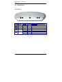
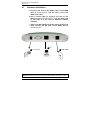
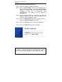
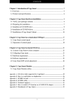
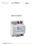
+
X7721r/X7721r User’s Manual
Version 1.0
-1-
+
X7721r/X7721r User’s Manual
Version 1.0
XAVi Technologies Corporation
Tel: +886-2-2995-7953
9F, No. 129, Hsing Te Road, Sanchung City,
Taipei Hsien 241,
Taiwan
Copyright © 2003, XAVi Technologies Corporation
Information in this manual is subject to change without notice. No part of this manual
may be reproduced or transmitted in any form or by any means, electronic or
mechanical, including photocopying or scanning, for any purpose, without the written
permission of XAVi Technologies Corporation.
XAVi Technologies Corporation provides this documentation without warranty of any
kind, implied or expressed, including, but not limited to, the implied warranties of
merchantability and fitness for a particular purpose.
-2-
+
X7721r/X7721r User’s Manual
Version 1.0
Table of Contents
Chapter 1 – Getting Started
I.
II.
III.
IV.
V.
Overview…………………………………….………….……….……… 6
Features…………………………………………………………..…….. 7
Packaging……………………………………….…….………………… 8
Safety Guidelines………………………………………………………. 9
Appearance…………………………………..………………….…….. 10
Front Panel…………………………………………………….……..…10
Rear Panel………………………………………………………..…… 11
VI. Hardware Installation…………………………………………………. 12
VII. Management…………………..………………..…..…….…………... 13
VIII. Default Values…………….……..……………………………………. 14
IX. Software Upgrade……………………..……………………………… 15
Chapter 2 – Command Line Interface
I.
II.
Console Setup..…………….………….………………..….…..…….. 17
CLI Commands……...……………………………..…………………. 18
1. Main Menu Commands…………………………………………. 18
2. LAN Menu Commands…….…………..………………….…… 21
Chapter 3 – Web Management Interface
I.
II.
Overview……………………………………………………………. 22
Preparation…………………………………………………………. 22
1. Login………………………………………………………………. 23
2. Connection Settings………………….………………………….. 24
2.1 RFC 1483 Bridge……..……………..………….………….. 25
2.1.1 RFC 1483 Bridge with NAT……………….……… 27
2.2 RFC 1483 Route………..………..……………….…………29
2.3 PPP over ATM (PPPoA)…………………………………… 31
2.4 PPP over Ethernet (PPPoE)…..………….……….……… 33
2.5 IP over ATM (IPoA).……….…………..…………..………. 35
3. Advanced Settings………………..………..………….………… 37
3.1 NAPT (Network Address Port Translation)……….……… 37
3.2 Static Routes……………………………………….……….. 38
3.3 DNS Relay…………………………………………………... 40
3.4 Security….…………………………………………………... 41
3.4.1 Security state………………………………………….41
3.4.2 Security level……....………………………………….42
3.4.3 Security interfaces...………………………………….43
-3-
+
X7721r/X7721r User’s Manual
Version 1.0
Table of Contents
4.
5.
6.
3.4.4 Policies, Triggers, Intrusion Detection..…………….44
3.4.4.1 Security Policy Configuration……………….45
3.4.4.2 Security Triggers…………….……………….49
3.4.4.3 Intrusion Detection…………..……………….50
3.4.4.4 Default Security Policies…………………….51
System Settings………………………………………………….. 52
4.1 Local LAN IP………………………………………………… 52
4.2 DHCP Server……………………………………………….. 53
4.3 Management………………………………………………… 54
4.3.1 Edit User Details…………….……………………...54
4.3.2 Add Users……………..……………………………. 55
4.3.3 Delete Users………….………..…..………..……...56
4.4 Ethernet……………………………………………………… 57
Modem Status……………….……………………….…….…….. 58
Maintenance…………………..…………………………..……… 60
6.1 Error Log…………………………………………………….. 60
6.2 Modem Upgrade………….………………………………… 61
6.3 Backup/Restore………………..…………………………… 61
6.4 Restart……………………………………………………….. 62
6.5 Save………………………………………………………….. 62
Appendix A – Specifications
A1.
A2.
Hardware Specifications..…………………………………….………….. 63
Software Specifications……….…………………………….…………….64
Appendix B – Warranties
B1.
B2.
B3.
Product Warranty……………………………..………………………….. 65
Warranty Repair………………………………………………………….. 66
Out-of-Warranty Repair………………………………………………….. 66
Appendix C – Regulations
C1.
C2.
C3.
FCC Part 15 Notice…………………………………….……………….. 67
IC CS-03 Notice………..………………………………..………………... 68
UL Safety Regulations...………………………………..………………... 69
Contact Information……………………………………………………….… 70
-4-
+
X7721r/X7721r User’s Manual
Version 1.0
Revision Marks
Revision
V 1.0
Date
December 12, 2003
Notes
Software Version: 1.02XAT0.7721A
-5-
+
X7721r/X7721r User’s Manual
Version 1.0
Chapter 1
Getting Started
I.
Overview
The X7721r/X7721r+ is a multi-mode ADSL/ADSL2 router, which
complies with ANSI T1.413 Issue 2, ITU G.992.1 (X7721r/X7721r+),
ITU G.992.2, G.992.3, G.992.4, G.992.5 (X7721r+ only), Annex A,
and ETSI ITS 101388 ADSL standards. The X7001r+ supports
ADSL2+ as well. The X7001r/X7721r+ provides high-speed Internet
access via one WAN port over ATM over ADSL, and also connects to
the corporate network via a 10/100BaseT Ethernet port. It supports
multiple protocols such as PPP (RFC 2364), IP (RFC 2225/RFC
1577), and RFC 1483 over ATM over ADSL, and PPP (RFC 2516)
over Ethernet. X7001r/X7001r+ offers convenient configuration and
management locally by telnet, SNMP, and a web-browser through the
Ethernet interface, and remotely through the ADSL interface.
-6-
+
X7721r/X7721r User’s Manual
Version 1.0
II.
Features
High Speed Asymmetrical Data Transmission on Twisted
Copper Pair Wire
Service providers can deploy ADSL rapidly over existing wire
infrastructure (POTS or ISDN line)
Interchangeable between Bridge and Router mode
RFC 1483 Bridge and Routing over ATM over ADSL
PPPoE, and IPoA, and PPPoA Routing over ADSL
10/100BaseT Ethernet Port for PC/LAN connection
High quality, simple operation, and low power consumption
Compatible and interoperable with most central office side
ADSL DSLAM or Multi-service Access Systems
Local OAM&P through command line interface via RS-232
craft port
Configuration and management with Telnet through the
Ethernet interface, and remote Telnet through ADSL
interface
Firmware upgradeable through TFTP, HTTP
Interoperability complies with TR-48
-7-
+
X7721r/X7721r User’s Manual
Version 1.0
III. Packaging
This package consists of the following items:
X7721r/X7721r+ ADSL device
unit
RJ-45 Cable
RJ-11 Cable
AC Adapter
User’s Manual CD
-8-
+
X7721r/X7721r User’s Manual
Version 1.0
IV. Safety Guidelines
In order to reduce the risk of fire, electric shock and injury, please
adhere to the following safety guidelines.
Carefully follow the instructions in this manual; also follow
all instruction labels on this device.
Except for the power adapter supplied, this device should not
be connected to any other adapters.
Do not spill liquid of any kind on this device.
Do not place the unit on an unstable stand or table. This unit
may drop and become damaged.
Do not expose this unit to direct sunlight.
Do not place any hot devices close to this unit, as they may
degrade or cause damage to the unit.
Do not place any heavy objects on top of this unit.
Do not use liquid cleaners or aerosol cleaners. Use a soft dry
cloth for cleaning.
-9-
+
X7721r/X7721r User’s Manual
Version 1.0
V.
Appearance
Front Panel
12
1
2
3
4
5
3
45
Label
LED
Status
Color
100M
ON
Green
10M
ON
Green
10M Ethernet transmitting.
PWR
ON
Green
Power supply is connected.
WAN
Blinking
Green
Training with DSLAM.
ON
Green
ADSL link is ready.
Blinking
RED
Booting up.
ON
RED
Error.
ALM
- 10 -
Description
100M Ethernet transmitting.
+
X7721r/X7721r User’s Manual
Version 1.0
Rear Panel
1
1
2
3
4
2
Label
PWR
ETHERNET
RESET
WAN
3 4
Description
Power jack; connect to a power adapter.
RJ-45 port; connect to a PC or LAN.
Reset the modem back to factory settings by holding
down on this button.
RJ-11 port; connect to the ADSL outlet.
- 11 -
+
X7721r/X7721r User’s Manual
Version 1.0
VI.
Hardware Installation
1. Connect one end of the ADSL cable to the WAN
port of X7721r/X7721r+ and the other end to the
ADSL wall outlet.
2. Use a RJ-45 cable to connect one end to the
Ethernet port of X7721r/X7721r+ and the other end
to the LAN or a PC with an Ethernet adapter
installed.
3. Plug in the AC adapter to the AC power socket, and
then connect the DC jack to the PWR inlet of
X7721r/X7721r+.
2 PC
3 Power Supply
1 ADSL Outlet
Note: Be sure to use a RJ-45 crossover cable while connecting to a hub.
- 12 -
+
X7721r/X7721r User’s Manual
Version 1.0
VII.
Management
Console Port – use the RS-232 cable for connecting
X7721r/X7721r+ to a console terminal or a PC running a
terminal emulation program, such as Hyper Terminal. (For
further details, See Chapter 2: Command Line Interface)
Local Ethernet Port (telnet) – connect the Ethernet port to
your local area network or directly to a PC, “Telnet”
X7721r/X7721r+ from any workstation in the LAN. The
default local Ethernet IP address is “192.168.1.1”.
Local Ethernet Port (web-browser) – connect the
Ethernet port to your local area network or directly to a PC.
Launch your web browser and enter default local Ethernet
IP address “192.168.1.1” into the address bar.
ADSL Port from Remote Site – while the ADSL
connection is in service, you may remotely “Telnet”
X7721r/X7721r+ from a workstation connected to the CO
equipment.
Note: As operating an ADSL device requires technical know-how and
experience, it is recommended that only qualified technical staff manage
X7721r/X7721r+. Therefore, a password authentication is required
when you enter the command line and Web interface. See the Default
Values section to obtain the password.
- 13 -
+
X7721r/X7721r User’s Manual
Version 1.0
VIII.
Default Values
X7721r/X7721r+ is pre-configured with the following parameters; you
may also re-load the default parameters by typing Restore in the
command line interface or using the Restart link in the Web
interface.
Default Mode: Bridge
Username/Password: admin
Bridge Mode Setting
WAN and ADSL
Ethernet (local) IP: 192.168.1.1
Local Line Code: Multi-mode
Subnet Mask: 255.255.255.0
Trellis Mode: Enable
Full Duplex: Auto
FDM Mode: Fdm
Protocol: RFC1483, Bridge Mode
Coding Gain: Multi
VPI/VCI: 8/35
Transmit Power Attenuation: 0dB
Class (QoS): UBR
Spanning Tree: Disable
Packet Filter: Any
Router Mode Setting
DHCP Server: Disable
Ethernet (local) IP: 192.168.1.1
DNS Relay: Disable
Subnet Mask: 255.255.255.0
Full Duplex: Auto
Note: The Username and Password are case-sensitive.
- 14 -
+
X7721r/X7721r User’s Manual
Version 1.0
IX.
Software Upgrade
You may easily upgrade X7721r/X7721r+ embedded software by
obtaining the compressed upgrade kit from the service provider and
then following the steps for upgrading through either a DOS prompt
or a Web-browser:
Software upgrade through a DOS prompt
Step 1. Extract the ZIP file for updated firmware.
Step 2. Connect X7721r/X7721r+ via the local Ethernet port or
remote ADSL link, making sure that the X7721r/X7721r+
Ethernet IP address and your terminal are properly
configured so that you can successfully “ping”
X7721r/X7721r+. The default local IP address is
“192.168.1.1”.
Step 3. Under the DOS prompt, execute the command “xupgrade
<IP address of X7721r/X7721r+ >”, for instance, “xupgrade
192.168.1.1”.
Step 4. This upgrading process may last as long as 60 seconds.
Step 5. Reboot X7721r/X7721r+ with new software.
Note: Strictly maintain stable power to X7721r/X7721r+ while upgrading
its software. If the power fails during the upgrading process, contents in
the memory could be destroyed, and the system may hang. In such a
case, you must call the dealer or system integrator for repairs.
- 15 -
+
X7721r/X7721r User’s Manual
Version 1.0
Software upgrade through a Web-browser
Step 1. Extract the ZIP file for updated firmware.
Step 2. Connect X7721r/X7721r+ via the local Ethernet port or
remote ADSL link, making sure that the X7721r/X7721r+
Ethernet IP address and your terminal are properly
configured so that you can successfully “ping”
X7721r/X7721r+. The default local IP address is
“192.168.1.1”.
Step 3. Launch the Web browser (IE or Netscape), and enter the
default IP address 192.168.1.1 into the address bar to
access the Web management page.
Step 4. Click on the Maintenance link in the navigation bar and
then on the Modem Upgrade link below it.
Step 5. Click on the Browse button to select the upgrade file.
Step 6. Click on the Update button when completed.
Note: Strictly maintain stable power to X7721r/X7721r+ while upgrading
its software. If the power fails during the upgrading process, contents
in the memory could be destroyed, and the system may hang. In
such a case, you must call the dealer or system integrator for repairs.
- 16 -
+
X7721r/X7721r User’s Manual
Version 1.0
Chapter 2
Command Line Interface
I.
Console Setup
Connect the RS-232 console port to an ASCII data terminal or a PC
with Windows serial Terminal mode of VT-100 (Hyper Terminal). To
Start the Hyper-terminal, follow the steps below.
1. Start "Hyper-terminal" program
On Windows 98 or Windows NT:
Click on the Start button
Programs
Accessories
Hyper
Terminal Group
Double Click “Hypertrm.exe”
Enter a
Connection Name
Select Icon
Click OK
2. Select a COM port to communicate with X7721r/X7721r+
Choose Direct to COM1 or Direct to COM2 and click on OK
3. Set Port Properties
Port Setting:
Bit per second: 9600
Data bits: 8
Parity bits: None
Stop bits: 1
Flow Control: None
Settings:
Function, arrow, and ctrl keys act as: Windows keys
Emulation: Auto-detect
Back-scroll buffer lines: 500
ASCII Setup:
Echo typed characters locally: enable
Line delay: 0 milliseconds
Character line feeds incoming line ends: enable
- 17 -
+
X7721r/X7721r User’s Manual
Version 1.0
III. CLI Commands
1. Main Menu Commands
Type “?” following the “→” to retrieve a list of commands under the
main menu to begin the configuration.
Command
Syntax
Description / Parameters
Display
Lan
→ display
→ lan
Restart
Restore
Ping
→ restart
→ restore
→ ping <ipAddress>
Save
→ save
Displays the configuration of IP
Enters the LAN menu
(See LAN Menu commands for
more details)
Reboots the modem
Sets all configurations to default
Pings the specified IP address for
testing purposes
Saves the current configuration
DISPLAY
Displays the IP address, subnet mask and software version.
Syntax: display
→ display
Version : 1.02XAT0.7721A (1.02XAT0.7721A 09/Dec/2003 16:50)
IP Interface: iplan
Ipaddr : 192.168.1.1
Mask : 255.255.255.0
→
LAN
Enters the lan menu
Syntax: lan
→ lan
lan>
- 18 -
+
X7721r/X7721r User’s Manual
Version 1.0
RESTART
Restarts the modem.
Syntax: restart
→ restart
NBfs1Z
PP Boot 9.0.3.19 (28 July 2003)
Copyright (c) 2003 GlobespanVirata, Inc.
SDRAM size = 0x1000000
NP
i
0%
i
4%
i
8%
i
13%
i
17%
i
22%
i
27%
i
31%
i
36%
i
41%
i
46%
i
51%
i
57%
i
62%
i
66%
i
71%
i
76%
i
83%
i
90%
i 100%
Login:
- 19 -
+
X7721r/X7721r User’s Manual
Version 1.0
RESTORE
Sets all configurations to factory default settings.
Syntax: restore
→ restore
Restoring factory defaults...
→
PING
Pings a specified IP address.
Syntax: ping <ipAddress>
Example: ping 192.168.0.81
→ ping 192.168.1.1
ping: PING 192.168.1.1: 32 data bytes
ping: 40 bytes from 192.168.1.1: seq=0, ttl=128, rtt<10ms192.168.0.81
→
SAVE
Saves the current configuration.
Syntax: save
→ save
Wait for 'configuration saved' message...
Saving configuration...
Configuration saved.
→
- 20 -
+
X7721r/X7721r User’s Manual
Version 1.0
2.
LAN Menu Commands
Type “lan” following the “→” to enter the LAN menu.
Command
setip
Syntax
Description / Parameters
lan→ setip
<ipAddresss>
[<subnet mask>]
Configures IP settings
SETIP
Configures the IP address and subnet mask of X7721r/X7721r+.
Syntax: setip <ipaddress>[<subnet mask>]
Example: setip 192.168.1.10 255.255.255.0
lan> setip 192.168.1.10 255.255.255.0
lan>
- 21 -
+
X7721r/X7721r User’s Manual
Version 1.0
Chapter 3
Web Management Interface
I.
Overview
The Web Management Interface is provided in order to configure
X7721r/X7721r+ as easily as possible. It provides a user-friendly
graphical interface through a Web platform. You may configure
bridge or router functions to accommodate your device needs. In the
section below, each configuration item is described in detail.
II.
Preparation
1. Please refer to the hardware installation procedure in
Chapter 1 to install X7721r/X7721r+.
2. You should configure your PC to the same IP subnet as the
X7721r/X7721r+.
Example:
X7721r/X7721r+: 192.168.1.1
Your PC: 192.168.1.x
3. Connect your PC to X7721r/X7721r+ and make sure that the
PING function is working properly. The default IP address of
this device is 192.168.1.1
4. Launch the Web browser (IE or Netscape), and enter the
default IP address 192.168.1.1 into the address bar to
access the Web management page.
5. The Login dialog box will appear first.
- 22 -
+
X7721r/X7721r User’s Manual
Version 1.0
1. Login
The Enter Network password window will pop up when
starting the configuration. With the window active, type admin
for both User name and Password, and then click on the OK
button. You can also edit the username and password or add a
new profile (see section 4.3 Management for further details).
- 23 -
+
X7721r/X7721r User’s Manual
Version 1.0
2. Connection Settings
Click on the Connection Settings link
on the navigation bar.
This page lists the WAN connection
protocols that are available on this
device. Please read the following
instructions for creating each type of
WAN connection.
You can create multiple WAN connections for each of following
protocols:
2.1 RFC 1483 Bridge
2.1.1 RFC 1483 Bridge with NAT
2.2 RFC 1483 Route
2.3 PPP over ATM (PPPoA)
2.4 PPP over Ethernet (PPPoE)
2.5 IP over ATM (IPoA)
- 24 -
+
X7721r/X7721r User’s Manual
Version 1.0
2.1 RFC 1483 Bridge
Click on the Create new connection service link to display the
types of service available.
Select RFC1483 Bridge and then click on the Go to next step
button.
- 25 -
+
X7721r/X7721r User’s Manual
Version 1.0
You will then see the following screen:
VPI: Enter the VPI value into this box.
VCI: Enter the VCI value into this box.
Qos: Select the quality of service level from the menu
Encapsulation: Select LLC or VC-Mux from the menu.
Connection type: Select RFC1483 Bridge.
Packet Filter: Select the packet filter type from the menu.
Click on the Create this new service button to complete the
configuration.
- 26 -
+
X7721r/X7721r User’s Manual
Version 1.0
2.1.1
RFC 1483 Bridge with NAT
Click on the Create new connection service link to display the
types of service available.
Select RFC 1483 Bridge and then click on the Go to next step
button.
- 27 -
+
X7721r/X7721r User’s Manual
Version 1.0
You will then see the following screen. Be sure to select RFC1483
Bridge with NAT for Connection type.
VPI: Enter the VPI value into this box.
VCI: Enter the VCI value into this box.
Qos: Select the quality of service level from the menu
Encapsulation: Select LLC or VC-Mux from the menu.
Connection type: Select RFC1483 Bridge with NAT.
DHCP Client: Check this box if you would like the device to
receive its IP address from a DHCP server (if you select this
option, you do not need to enter an IP address or subnet mask).
IP Address: Enter the IP address of the device (if not using the
device as a DHCP client).
IP Subnet Mask: Enter the subnet mask of the IP address (if not
using the device as a DHCP client).
Click on the Create this new service button to complete the
configuration.
- 28 -
+
X7721r/X7721r User’s Manual
Version 1.0
2.2 RFC 1483 Route
Click on the Create new connection service link to display the
types of service available.
Select RFC 1483 Route and then click on the Go to next step
button.
- 29 -
+
X7721r/X7721r User’s Manual
Version 1.0
You will then see the following screen:
VPI: Enter the VPI value into this box.
VCI: Enter the VCI value into this box.
Qos: Select the quality of service level from the menu.
Encapsulation: Select LLC or VC-Mux from the menu.
DHCP Client: Check this box if you would like the device to
receive its IP address from a DHCP server (if you select this
option, you do not need to enter an IP address or subnet mask).
IP Address: Enter the IP address of the device (if not using the
device as a DHCP client).
IP Subnet Mask: Enter the subnet mask of the IP address (if not
using the device as a DHCP client).
Click on the Create this new service button to complete the
configuration.
- 30 -
+
X7721r/X7721r User’s Manual
Version 1.0
2.3 PPP over ATM (PPPoA)
Click on the Create new connection service link to display the
types of service available.
Select PPP over ATM and then click on the Go to next step button.
- 31 -
+
X7721r/X7721r User’s Manual
Version 1.0
You will then see the following screen:
VPI: Enter the VPI value into this box.
VCI: Enter the VCI value into this box.
Qos: Select the quality of service level from the menu.
Authentication: Select PAP or CHAP.
Username: Enter the user name for this connection (from ISP).
Password: Enter the password for this connection (from ISP).
Idle time: Enter a number for the idle time in seconds. This will
end the call if the connection is idle for the specified time (0
indicates that the call will not be ended).
Click on the Create this new service button to complete the
configuration.
- 32 -
+
X7721r/X7721r User’s Manual
Version 1.0
2.4 PPP over Ethernet (PPPoE)
Click on the Create new connection service link to display the
types of service available.
Select PPP over Ethernet and then click on the Go to next
step button.
- 33 -
+
X7721r/X7721r User’s Manual
Version 1.0
You will then see the following screen:
VPI: Enter the VPI value into this box.
VCI: Enter the VCI value into this box.
Qos: Select the quality of service level from the menu.
Authentication: Select PAP or CHAP.
Username: Enter the user name for this connection (from ISP).
Password: Enter the password for this connection (from ISP).
Idle time: Enter a number for the idle time in seconds. This will
end the call if the connection is idle for the specified time (0
indicates that the call will not be ended).
Click on the Create this new service button to complete the
configuration.
- 34 -
+
X7721r/X7721r User’s Manual
Version 1.0
2.5
IP over ATM (IpoA)
Click on the Create new connection service link to display the
types of service available.
Select IP over ATM and then click on the Go to next step
button.
- 35 -
+
X7721r/X7721r User’s Manual
Version 1.0
You will then see the following screen:
VPI: Enter the VPI value into this box.
VCI: Enter the VCI value into this box.
Qos: Select the quality of service level from the menu.
DHCP Client: Check this box if you would like the device to
receive its IP address from a DHCP server (if you select this
option, you do not need to enter an IP address or subnet mask).
IP Address: Enter the IP address of the device (if not using the
device as a DHCP client).
IP Subnet Mask: Enter the subnet mask of the IP address (if not
using the device as a DHCP client).
Click on the Create this new service button to complete the
configuration.
- 36 -
+
X7721r/X7721r User’s Manual
Version 1.0
3. Advanced Settings
Click on the Advanced Settings link on
the navigation bar.
This section includes NAPT (Network
Address Port Translation), Static
Routes, and DNS Relay. Each section
is described in detail below.
3.1 NAPT (Network Address Port Translation)
Click on the NAPT link in the navigation bar to view the NAPT
configuration page. This page displays the NAT status of the
available connections.
To enable NAT on an interface, click on the Enable NAT to
internal interfaces button.
To disable NAT on an interface, click on the Disable NAT to
internal interfaces button.
- 37 -
+
X7721r/X7721r User’s Manual
Version 1.0
You may map a port to an interface by clicking on the Add
Reserved Mapping link under the Disable NAT to internal
interfaces button. You will then see the following screen:
Internal IP Address: Enter the IP address to which you would
like to map a protocol and port.
Transport Type: select a protocol from the drop-down list.
Port: Enter the port number of that protocol.
Click on the Add Reserved Mapping button when completed.
3.2 Static Routes
Click on the Static Routes link in the navigation bar to view the
IP Routing table.
Click on the Create new IP4 Route button to add a new route.
- 38 -
+
X7721r/X7721r User’s Manual
Version 1.0
You will then see the following screen:
Destination: Enter the IP Address of the destination router.
Gateway: Enter the IP Address of the gateway.
Mask: Enter the subnet mask of the IP address.
Metric: Enter the number of hops required to reach the
destination.
Click on the Add Static Route button when completed.
- 39 -
+
X7721r/X7721r User’s Manual
Version 1.0
3.3 DNS Relay
Click on the DNS Relay link in the navigation bar to view the
DNS Relay table.
Enter the Primary DNS address into the text box and then click
on the Apply button.
On the next screen, you may add a Secondary DNS address into
the text box. Click on the Apply button to continue.
To delete a DNS address, check the Delete? box, and click on
the Apply button.
- 40 -
+
X7721r/X7721r User’s Manual
Version 1.0
3.4 Security
Click on the Security link in the navigation bar to view or change the
security interface settings.
3.4.1
Security State
Use the toggle switch to enable or disable Security, Firewall,
and Intrusion Detection.
Click on the Change State button to apply the new settings.
Configurations for advanced security settings will apply only if
Security is enabled in the Security State section.
Configurations for security policies and intrusion detection will
apply only if Firewall is enabled in the Security State section.
Configurations for intrusion detection will apply only if Intrusion
Detection is enabled in the Security State section.
- 41 -
+
X7721r/X7721r User’s Manual
Version 1.0
3.4.2
Security Level
You must set Firewall to Enabled in order to choose a security
level.
Choose a value for Security Level from the drop-down menu.
Click on the Change State button to apply the new settings.
- 42 -
+
X7721r/X7721r User’s Manual
Version 1.0
3.4.3
Security Interfaces
This table lists the name, type, and NAT status of each security
interface.
To enable NAT on an interface, click on the Enable NAT to
internal interfaces button.
To disable NAT on an interface, click on the Disable NAT to
internal interfaces button.
To map a port to an interface, click on the Advanced NAT
Configuration link under the Disable NAT to internal
interfaces button. Choose the Add Reserved Mapping link on
the next screen. See the Add Reserved Mapping section (next
page) for instructions.
To delete an interface, click on the Delete Interface link in the
corresponding row.
To add another interface, click on the Add Interface link below
the table.
- 43 -
+
X7721r/X7721r User’s Manual
Version 1.0
Add Reserved Mapping
Internal IP Address: Enter the IP address to which you would
like to map a protocol and port.
Transport Type: select a protocol from the drop down list.
Port: Enter a port number for the selected protocol.
Click on the Add Reserved Mapping button when completed.
3.4.4
Policies, Triggers, and Intrusion detection
To configure security policies, security triggers, or intrusion
detection, choose the corresponding link.
- 44 -
+
X7721r/X7721r User’s Manual
Version 1.0
3.4.4.1
Security Policy Configuration
To add a new security policy, choose the Security Policy
Configuration link, and then choose the New Policy link on the
next screen. You will then see the following screen:
Choose the types of interfaces from the menus between which
you would like to configure the security policy.
Choose whether the validators (selection criteria) will serve to
block or allow traffic.
Click on the Apply button. You will then see the following screen:
To configure a new policy, click on the Port Filters link and/or
the Host Validators link in the Current Security Policies table.
To delete a security policy, click on the Delete button in the
corresponding row of the Current Security Policies table.
- 45 -
+
X7721r/X7721r User’s Manual
Version 1.0
Port Filters
To set the port filters, click on the Port Filters link in the Current
Security Policies table. On the next screen, choose Add TCP or
UDP Filter or Add Raw IP Filter link depending on the type of
filter you want to create.
Add TCP or UDP Filter
Enter the criteria for the port filter into the table.
Ensure that the Protocol is appropriate for your interface.
Port filter default values for “allow” criteria will allow all traffic to
pass (as shown in this example).
Port filter default values for “block” criteria will block all traffic.
Filter criteria for source and destination ports define the range
within which traffic will be allowed/blocked by the filter.
Filter criteria for source and destination addresses and subnet
masks do not override port criteria, but add additional criteria for
the port filter.
Click on the Apply button to return to the list of defined port
filters.
To delete a port filter, click on the Delete button of the
corresponding row of the port filters table.
- 46 -
+
X7721r/X7721r User’s Manual
Version 1.0
Add Raw IP filter
Enter the criteria for the port filter into the table.
Default values for “allow” criteria will allow all traffic to pass (as
shown in this example).
Default values for “block” criteria will block all traffic.
Enter the IP Protocol that the security interface will allow.
Filter criteria for source and destination IP addresses and subnet
masks define the values that will be allowed by the “allow” filter,
and define the values that will be blocked by the “block” filter.
Filter criteria for source and destination IP address and subnet
mask do not override IP protocol criteria, but add additional
criteria for the port filter.
Click on the Apply button to return to the list of defined port
filters.
To delete a port filter, click on the Delete button of the
corresponding row of the port filters table.
- 47 -
+
X7721r/X7721r User’s Manual
Version 1.0
Host Validators
To set the host validators, click on the Host Validators link in the
Current Security Policies table. On the next screen, choose the
Add Host Validator link .
You will then see the following screen:
Enter the IP Address and subnet mask for the host that you want
to have validated.
Indicate whether the host address should be validated for
incoming traffic, outgoing traffic, or both by selecting a value from
the Direction drop-down box.
Packets from the host address that you enter in the host
validator will be blocked or allowed according to the way the
validator was defined when the interface was created.
Click on the Apply button to return to the list of defined host
validators.
To delete a host validator, click on the Delete button of the
corresponding row of the host validators table.
- 48 -
+
X7721r/X7721r User’s Manual
Version 1.0
3.4.4.2
Security Triggers
Security triggers can be defined on the following interfaces:
External and internal
External and DMZ
DMZ and internal
To add a new security trigger, choose the Security Trigger
Configuration link, and then choose the New Trigger link on the
next screen.
You will then see the following screen:
Enter values into the table to define the new security trigger.
The security trigger adds traffic flow constraints to the security
policies.
The security trigger remains active even when the firewall is
disabled.
Click on the Apply button to return to the list of defined security
triggers.
To delete a security trigger, click on the Delete button of the
corresponding row of the security triggers table.
- 49 -
+
X7721r/X7721r User’s Manual
Version 1.0
3.4.4.3
Intrusion Detection
Intrusion detection can be defined on any interface with an external
endpoint.
To configure firewall intrusion detection, choose the Configure
Intrusion Detection link.
Firewall intrusion detection can be configured only if Intrusion
Detection is enabled in the Security State section.
You will then see the following screen:
Enter values into the table to set conditions for intrusion
detection.
If Use Blacklist is set to true, clicking on the Clear Blacklist
button will clear the blacklist.
Click on the Apply button to save the settings.
- 50 -
+
X7721r/X7721r User’s Manual
Version 1.0
3.4.4.4
Default Security Policies
Default security policies, including port filters and security triggers,
are defined for the low, medium, and high security levels.
For example, if the High security level is selected, security policies
for every type of interface are already defined, as shown below. Each
security policy applies only if its corresponding interface is defined by
the user.
The pre-defined security settings for any security level include
port filter settings and security trigger settings.
To override the pre-defined settings, you can delete the policies,
port filters, or security triggers as required.
User-defined host validators for pre-defined security policies will
act to block traffic by default.
- 51 -
+
X7721r/X7721r User’s Manual
Version 1.0
4.
System Settings
Click on the System Settings link on
the navigation bar.
This section includes Local LAN IP,
DHCP Server, Management, and
ADSL. Each section is described in
detail below.
4.1 Local LAN IP
Click on the Local LAN IP link in the navigation bar to view the
LAN IP table.
Define the primary IP address and subnet mask of your device
here, and make changes by editing the IP address in the text
box.
Click on the Apply button to save the configurations.
- 52 -
+
X7721r/X7721r User’s Manual
Version 1.0
4.2 DHCP Server
Click on the DHCP Server link in the navigation bar to view the
DHCP Server settings.
This device can be set up to perform the service of a DHCP
Server and enables data connection between multiple PCs
through the configuration of IP address ranges and lease times.
Enable DHCP server: Make sure that you check this box if you
would like this device to function as a DHCP server.
Starting IP address: Enter the IP address that you would like
the DHCP server to start assigning addresses from.
Ending IP address: Enter the last IP address that you would like
the DHCP server to assign.
Lease duration: Enter the amount of time that an IP address
can be used by a client.
Primary DNS address: Enter the Primary DNS IP address.
Secondary DNS address: Enter the Secondary DNS IP
address.
Use Router as Default Gateway: Make sure that you check this
box if you would like this device to be the default gateway.
Click on the Apply button when completed.
- 53 -
+
X7721r/X7721r User’s Manual
Version 1.0
4.3 Management
Click on the Management link in the navigation bar to view the user
login details. Here you may edit user login details or add/delete users.
Each item is described below.
4.3.1
Edit User Details
Click on the Edit link to change the settings of the admin user.
On this page you may change the settings of the admin user.
Username: Enter a new username if you would like to change
this one.
Password: Enter a new password if you would like to change
this one (highly recommended for security purposes).
May Login?: Do not change this setting to false, otherwise
you will not be able to log into the device.
Comment: You may add a comment/description here.
Click on the Edit this User button to complete this configuration.
- 54 -
+
X7721r/X7721r User’s Manual
Version 1.0
4.3.2
Add Users
Click on the Create new user link to add a user.
On this page you may fill in the details for the new user.
Username: Enter a new username for the new user.
Password: Enter a password for the new user.
May Login?: Do not change this setting to false, otherwise
you will not be able to log into the device.
Comment: You may add a comment/description here.
Click on the Create this User button to complete this
configuration. You will then see the new user added to the table.
- 55 -
+
X7721r/X7721r User’s Manual
Version 1.0
4.3.3
Delete Users
In order to delete an existing user, click on the Delete link next to
the user’s name.
You will then be asked to confirm if you would like to delete this
user. Click on the Delete this User button.
- 56 -
+
X7721r/X7721r User’s Manual
Version 1.0
4.4 Ethernet
Click on the Ethernet link on the navigation bar. This page
displays a table of the default Ethernet settings. This includes
port, configuration, linked status, and speed/duplex.
You can choose a value for speed/duplex from the drop-down
menu.
Click on the Change button to save the changes.
- 57 -
+
X7721r/X7721r User’s Manual
Version 1.0
- 58 -
+
X7721r/X7721r User’s Manual
Version 1.0
5. Modem Status
Click on the Modem Status link on the
navigation bar. You will then see the
following page.
Listed on this page are the port
connection status, LAN status, WAN
status, ADSL status, and device status.
- 59 -
+
X7721r/X7721r User’s Manual
Version 1.0
LAN Status: This table displays the LAN IP address, and
indicates whether this device is used as a DHCP server. Click on
the Detail… link to view the LAN statistics. This page displays
the MAC address and transfer statistics.
WAN Status: This table displays the WAN IP address. Click on
the Detail… link to view the WAN statistics.
ADSL Status: This table displays the operation status and firmware
version.
Device Status: This table displays the device uptime and software
version.
- 60 -
+
X7721r/X7721r User’s Manual
Version 1.0
6. Maintenance
Click on the Maintenance link on the
navigation bar.
This section includes Error Log, Modem
Upgrade, Backup/Restore, Restart and
Save. Each section is described in detail
below.
6.1 Error Log
Click on the Error Log link in the navigation bar to view the
history of errors.
Click on the Clear Logs button to clear the log table.
- 61 -
+
X7721r/X7721r User’s Manual
Version 1.0
6.2 Modem Upgrade
Click on the Modem Upgrade link in the navigation bar to view
the modem upgrade page.
Click on the Browse button to select the upgrade file.
Click on the Update button when completed.
6.3 Backup/Restore
Click on the Backup/Restore link in the navigation bar to view
the backup/restore configuration page.
To back up a configuration file, click on the Backup button, and
then select a location where you would like to save the file.
To restore a configuration file, click on the Browse button to
select the backup file, and then click on the Restore button to
restore the configuration.
- 62 -
+
X7721r/X7721r User’s Manual
Version 1.0
6.4 Restart
Click on the Restart link in the navigation bar to view the restart
page.
To restart the modem, click on the Restart button. You may also
check the Reset to factory default settings box if you would
like to restart the modem with the factory settings.
6.5 Save
Click on the Save link in the navigation bar to view the save
confirmation page.
If you would like to save the current configuration, click on the
Save button.
- 63 -
+
X7721r/X7721r User’s Manual
Version 1.0
Appendix A – Specifications
A1. Hardware Specifications
Local Interface
• Type – 10/100BaseTX Ethernet, IEEE 802.3
• Connector – RJ-45
WAN ADSL Line Interface
• Compliant with ADSL ITU G.992.1, G.992.2, G.992.3 and ANSI T1. 413
Issue 2
• Line Impedance: 100 Ω
• Connection Loops: One (pair wire)
• Connector: RJ-11
•
•
•
•
•
Indicators
PWR – Green LED indicates power and operation
ACT – Green LED indicates LAN data Transmitting / Receiving
LINK – Green LED indicates LAN data link status
WAN – Green LED indicates ADSL data link
ALM – Red LED indicates data error or operation fault
OAM&P
• Local: RS-232, Telnet or Web management via Ethernet
• Remote: Telnet or Web Management
•
•
•
•
Environment
Operation Temperature: 0°C ~ 45°C
Operation Humidity: 5% ~ 95%
Storage Temperature: -20 ~ +85°C
Storage Humidity: 5%~95%
Power
• AC Adapter: Input 110/220VAC, 50/60Hz; Output 15VAC 1A
• Power Consumption: Less than 9 Watts
Certificates
• CE, CB
- 64 -
+
X7721r/X7721r User’s Manual
Version 1.0
A2. Software Specifications
•
•
•
•
•
•
•
ATM
ATM Cells over ADSL, AAL5
Bridge mode: Supports 8 PVCs
Router mode: Supports 5 PVCs
Supports UBR, CBR, VBR-nrt, and VBR-rt
ATM Forum UNI 3.0, UNI 3.1, UNI 4.0
ILMI 4.0
PPP over ATM PVC (RFC 2364)
•
•
•
•
•
Bridging
Transparent Bridging (IEEE 802.1D)
RFC2684 (RFC 1483) Bridged
Spanning Tree Protocol (IEEE 802.1D)
IP and PPPoE packet filtering
IP Multicast IGMP Proxy
•
•
•
•
•
•
•
Routing
IP routing, RIP1, RIP2, OSPF and static routing
PPPoE, and IP, PPP over ATM
PAP and CHAP
RFC2684 (RFC1483) Routed
NAT/PAT with extensive ALG support
DNS relay
Multihoming (IP Aliasing)
•
•
•
•
•
•
•
•
Configuration and Network Management Features
DHCP client and server for IP management
Telnet for local or remote management
TFTP, HTTP for firmware upgrade and configuration
Web-based configuration and management configuration
SNMP v1, v2, and v3 agent
SNMP MIB II
DSL MIB
ATM MIB
- 65 -
+
X7721r/X7721r User’s Manual
Version 1.0
Appendix B – Warranties
B1. Product Warranty
XAVi Technologies warrants that the ADSL unit will be free from
defects in material and workmanship for a period of twelve (12)
months from the date of shipment.
XAVi Technologies shall incur no liability under this warranty if
- The allegedly defective goods are not returned prepaid
to XAVi Technologies within thirty (30) days of the
discovery of the alleged defect and in accordance with
XAVi Technologies’ repair procedures; or
- XAVi Technologies’ tests disclose that the alleged
defect is not due to defects in material or workmanship.
XAVi Technologies’ liability shall be limited to either repair or
replacement of the defective goods, at XAVi Technologies’
option.
XAVi Technologies MARKS NO EXPRESS OR IMPLIED
WARRANTIES
REGARDING
THE
QUALITY,
MERCHANTABILITY, OR FITNESS FOR A PARTICULAR
PURPOSE BEYOND THOSE THAT APPEAR IN THE
APPLICABLE USER’S DOCUMETATION. XAVi SHALL NOT
BE RESPONSIBLE FOR CONSEQUENTIAL, INCIDENTAL,
OR PUNITIVE DAMAGE, INCLUDING, BUT NOT LIMITED TO,
LOSS OF PROFITS OR DAMAGES TO BUSINESS OR
BUSINESS RELATIONS. THIS WARRANTY IS IN LIEU OF
ALL OTHER WARRANTIES.
- 66 -
+
X7721r/X7721r User’s Manual
Version 1.0
B2. Warranty Repair
1. During the first three (3) months of ownership, XAVi
Technologies will repair or replace a defective product
covered under warranty within twenty-four (24) hours of
receipt of the product. During the fourth (4th) through twelfth
(12th) months of ownership, XAVi Technologies will repair or
replace a defective product covered under warranty within
ten (10) days of receipt of the product. The warranty period
for the replaced products shall be ninety (90) days or the
remainder of the warranty period of the original unit,
whichever is greater. XAVi Technologies will ship surface
freight. Expedited freight is at customer’s expense.
2. The customer must return the defective product to XAVi
Technologies within fourteen (14) days after the request for
replacement. If the defective product is not returned within
this time period, XAVi Technologies will bill the customer for
the product at list price.
B3. Out-of-Warranty Repair
XAVi Technologies will either repair or, at its option, replace a
defective product not covered under warranty within ten (10)
working days of its receipt. Repair charges are available from
the Repair Facility upon request. The warranty on a serviced
product is thirty (30) days measured from date of service.
Out-of-warranty repair charges are based upon the prices in
effect at the time of return.
- 67 -
+
X7721r/X7721r User’s Manual
Version 1.0
Appendix C – Regulations
C1. FCC Part 15 Notice
Warning: This equipment has been tested and found to comply with
the limits for a Class B digital device, pursuant to Part 15 to the FCC
rules. These limits are designed to provide reasonable protection
against harmful interference when the equipment is operated in a
residential environment. This equipment generates, used, and can
radiate radio frequency energy, and, if not installed and used in
accordance with the instruction manual, may cause harmful
interference to radio communications. Operation of this equipment in
a residential area is unlikely to cause harmful interference. But if it
does, the user will be required to correct the interference at his or her
own expense. The authority to operate this equipment is conditioned
by the requirement that no modifications will be made to the
equipment unless XAVi expressly approves the changes or
modifications.
- 68 -
+
X7721r/X7721r User’s Manual
Version 1.0
C2. IC CS-03 Notice
The Industry Canada label identifies certified equipment. This
certification means that the equipment meets certain
telecommunications network protective, operational, and safety
requirements as prescribed in appropriate Terminal Equipment
Technical Requirements document(s). The Department does
not guarantee that the equipment will operate to the user’s
satisfaction.
Before installing this equipment, users should make sure that it
is permissible to be connected to the facilities of the local
telecommunications company. An acceptable method of
connection must be used to install the equipment. The
customer should be aware that compliance with the above
conditions might not prevent degradation of service in some
situations.
Repairs to certified equipment should be coordinated by a
representative designated by the supplier. Any repairs or
alterations made by the user to this equipment, or equipment
malfunctions, may give the telecommunications company
cause to request the user to disconnect the equipment.
Users should ensure for their own protection that the electrical
ground connections of the power utility, telephone lines, and
internal metallic water pipe system, if present, are connected
together. This precaution may be particularly important in rural
areas.
Warning: Users should not attempt to make such connections
themselves, but should contact the appropriate electric inspection
authority or an electrician as appropriate.
- 69 -
+
X7721r/X7721r User’s Manual
Version 1.0
C3. UL Safety Regulations
Disconnect TNV circuit connector or before removing cover or
equivalent.
Disconnect TNV circuit connector(s) before disconnecting power.
Do not use this product near water for example, near a bathtub,
washbowl, and kitchen sink or laundry tub, in a wet basement, or
near a swimming pool.
Avoid using a telephone (other than a cordless type) during an
electrical storm. There may be a remote risk of electric shock
from lightening.
Do not use the telephone to report a gas leak in the vicinity of the
leak.
Use only the power cord batteries indicated in this manual. Do
not dispose of batteries in a fire, as they may explode. Check
with local codes for possible special disposal instructions.
No. 26 AWG Telephone Line Cord shall either be provided with the
equipment or shall be described in the safety instruction. If fuse (F1)
is not present, see the caution statement listed below:
CAUTION: To reduce the risk of fire, use only No. 26 AWG or larger
UL Listed or CSA Certified Telecommunication Line Cord.
- 70 -
+
X7721r/X7721r User’s Manual
Version 1.0
Contact Information
You can help us serve you better by sending us your comments and
feedback. Listed below are the addresses, telephone and fax
numbers of our offices. You can also visit us on the World Wide Web
at www.xavi.com.tw for more information. We look forward to hearing
from you!
World Headquarter
XAVi Technologies Corporation
9F, No. 129 Hsing Te Road, Sanchung City
Taipei Hsien 241, Taiwan,
Tel: +886-2-2995-7953 Fax: +886-2-2995-7954
USA Branch Office
1463 Madera Road, N. Suite 182 Simi Valley
CA 93065, USA
Tel: +805-578-9774
European Branch Office
Papenreye 27, 22453 Hamburg
Germany
Tel: +49-40-589510-0 Fax: +49-40-589510-29
China Agency
Room 401, Floor 4, #608 ZhaoJiaBang Road
Shanghai, 20031
Tel: +86-21-6431-8800 Fax: +86-21-6431-7885
- 71 -