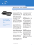
1
QoS Access Router SETUP GUIDE Model Q2300 Ethernet QoS Access Router Model Q2301 Ethernet QoS Access Router with Modem Document #650-00458-02 Copyright Copyright © 2004, 2006 by Kentrox, LLC. All rights reserved. Printed in the U.S.A. Specifications published here are current or planned as of the date of publication of this document. Because we are continuously improving and adding features to our products, Kentrox reserves the right to change specifications without prior notice. You may verify product specifications by contacting our office. In no event shall Kentrox be liable for any damages resulting from loss of data, loss of use, or loss of profits. Kentrox further disclaims any and all liability for indirect, incidental, special, consequential or other similar damages. This disclaimer of liability applies to all products, publications and services during and after the warranty period. Additional copyrights applicable to portions of this product: Copyright © 2003 GlobespanVirata, Inc. Copyright © 2003-2004 Ashley Laurent, Inc. Copyright © 1989-2001 SNMP Research, Inc. Copyright © 1995-1998 Eric Young ([email protected]) Revision History Trademark information Part # Date Description 650-00458-00 May 2004 Issue 1 650-00458-01 December 2004 Issue 2, release 1.30 650-00458-02 March 2006 Issue 3, release 1.35 Kentrox is a registered trademark and Q-Series is a trademark of Kentrox, LLC. All other product names are trademarks or registered trademarks of their respective owners. Who to contact for assistance If you need assistance with this product or have questions not answered by this manual, please first contact your reseller or visit our Support page on the Kentrox Web site at www.kentrox.com/support. For further information, see “Registration, warranty, support, and services” on page 5 of this manual. 2 Contents Preface . . . . . . . . . . . . . . . . . . . . . . . . . . . . . . . . . . . . . . . 5 Chapter 1 Before you begin. . . . . . . . . . . . . . . . . . . . . . . . . . . . . . . 7 Installation Summary. . . . . . . . . . . . . . . . . . . . . . . . . . . . . . . . 7 Pre-installation checklist . . . . . . . . . . . . . . . . . . . . . . . . . . . . . 8 Configuration worksheet . . . . . . . . . . . . . . . . . . . . . . . . . . . . . 9 Perform a power-on test. . . . . . . . . . . . . . . . . . . . . . . . . . . . . 13 Chapter 2 Installing the router. . . . . . . . . . . . . . . . . . . . . . . . . . . . 15 Installation shortcut for IT professionals . . . . . . . . . . . . . . . . 15 Step 1: Mount the router on a wall or in a rack . . . . . . . . . . . 16 Step 2: Set up a computer to access the router . . . . . . . . . . . 18 Step 3: Access the router’s graphical interface . . . . . . . . . . . 19 Step 4: Set a password for the default user . . . . . . . . . . . . . . 19 Step 5: Allow remote access (optional) . . . . . . . . . . . . . . . . . 20 Step 6: Enter the worksheet information . . . . . . . . . . . . . . . . 20 Step 7: Connect the cables . . . . . . . . . . . . . . . . . . . . . . . . . . . 23 Step 8: Save your configuration and restart. . . . . . . . . . . . . . 24 Step 9: Test access to the WAN . . . . . . . . . . . . . . . . . . . . . . . 24 If all else fails...reset . . . . . . . . . . . . . . . . . . . . . . . . . . . . . . . 24 3 4 Contents Preface This Setup Guide explains how to install and configure the Q2300 router (“the router”). The contents of this guide are divided into two chapters: Before you begin. This chapter contains a brief overview of the installation process and a configuration worksheet that should be completed before beginning the installation. Installing the router. This chapter describes step-by-step how to install, connect, and configure the router to the point where it is IP-accessible (that is, remotely manageable). Registration, warranty, support, and services To receive product news and announcements from Kentrox, please register your Kentrox products at www.kentrox.com/register. All Kentrox Q-Series routers carry a 1-year warranty beginning on the date of purchase. Units found to be defective within that warranty period will be repaired or replaced under the terms of the Kentrox warranty, which can be viewed online at www.kentrox.com/warranty. All product returns to Kentrox must include a Return Authorization number, which you can obtain by calling the Technical Assistance Center. Should you require technical assistance or are interested in training class availability, please visit the Kentrox Support web site at www.kentrox.com/support. Should you need further assistance, help may be available over the phone from your Kentrox-authorized reseller. Kentrox also offers fee-based phone support and priority support under a variety of maintenance plans. For all other inquiries, please visit www.kentrox.com or call (800) 733-5511. 5 General safety precautions This equipment has been designed to the highest quality standards of materials, workmanship and safety. Do not bypass any of the safety features of this equipment or operate this equipment in an improper environment. WARNING! To avoid hazard from electrical shock and/or fire, adhere to the safety practices listed in this section and identified within the instructions of this document. Use caution when installing or modifying communication lines. Dangerous voltages may be present. It is unsafe to install wiring during a lightning storm. Always disconnect all communication lines at the network interface and power connections from the wall outlets before servicing or disassembling this equipment. All wiring external to the product(s) should follow the provisions of the current local and national building codes or any wiring rules that apply. The equipment should be installed near the electrical outlet and be easily accessible. WARNING! Potentially hazardous voltages inside. Service should be performed only by qualified personnel. ADVERTISSEMENT!: Tensions Dangereuses à l'intérieur. Confier la maintenance à une personne qualifiée. WARNING! This equipment is electrically grounded only when it is connected to a grounded AC power outlet using the supplied AC–DC power adapter. 6 Preface C H A P T E 1 R Before you begin Installation Summary This guide will show you how to physically install the router and make it accessible from both the WAN and your LAN. Advanced features, which are explained in the User’s Guide, can then be configured by you or a network administrator using a computer on your LAN, or from a remote office over the WAN. For a first-time installation, allow about 15 minutes for each of the following: ❏ Looking through this manual and understanding the steps ❏ Installing the router and cables ❏ Setting up a computer to access the router through your Internet browser ❏ Performing the basic LAN and WAN configurations Add or subtract time depending on your experience and installation site readiness. Subsequent router installations can go much faster. NOTE Your router may have already been pre-configured by your network administrator, which would further simplify your installation tasks. Gather the necessary information Ask your network administrator or IT department for the information listed in the configuration worksheet on page 9. After physically installing the router, you will enter this information using the router’s graphical user interface (GUI) to set up basic network connectivity. NOTE The configuration worksheet contains the minimum information necessary to make the LAN and WAN interfaces functional in most remote-office installations. Not all parameters visible in the graphical interface are represented in the worksheet. The goal of this Setup Guide is to make the router accessible over the WAN to a network administrator who can later configure the advanced features. 7 Pre-installation checklist Take inventory If the router appears to have been damaged in shipping, return it to your place of purchase for a replacement. Check to make sure you received the following items with each router: ❏ Documentation CD (includes Adobe® Acrobat® PDF versions of this manual, the User’s Guide and the CLI Reference Guide) ❏ AC–DC power adapter and cable for use in North America ❏ One Ethernet LAN cable, Cat 5E, UTP 568B, 6’ ❏ RS-232 DTE cable adapter1, RJ45 to DE-9S, Kentrox catalog #77910 ❏ Two #8 wood screws and anchors for wall-mounting the router Optional accessories: ❏ Rack-mounting kit for 19” equipment racks, Kentrox catalog #77912 ❏ Ethernet cable, Cat 5E, UTP 568B, 6’, Kentrox catalog #93006212 ❏ One modem cable, 4-wire (modem-equipped Q2301 router only), Kentrox catalog #930xx210 (xx denotes length of cable). ❏ Spare AC–DC power adapter, Kentrox catalog #77911 Prepare the installation site The router requires the following for safe operation: ❏ Grounded, 100-240 volts AC, 50/60 Hz, power source ❏ At least 1/8” clearance above and 1” on each side for ventilation ❏ Temperature range: 0° to 50° C (32° to122° F) ❏ Humidity range: 5% to 95% relative humidity, non-condensing Computer requirements (for configuring the router): 1 8 ❏ Computer with monitor, keyboard, and mouse ❏ Internet browser software: Microsoft® Internet Explorer 5.5 or later; Netscape 7.1; or browser based on Mozilla 1.4 or later ❏ Network interface card (NIC) for connection to an Ethernet port on the router, or to an Ethernet LAN that will be connected to the router ❏ DHCP client setup, i.e., the computer automatically obtains its IP address from the router The RS-232 DTE cable adapter can be used with any straight-through cable, such as the Kentrox Ethernet cable, to connect a computer to the RS-232 control port for access to the command line interface (CLI). Before you begin Configuration worksheet All parameters in this worksheet should be considered a minimum configuration to enable the router to pass traffic. Ethernet LAN configuration In most cases, you can use the default LAN IP address and subnet mask. However, you must change these settings if you are installing the router on a LAN with static IP addresses, or where another device is already using the default Ethernet LAN IP address of 192.168.1.1. To change the default values, go to the Configure > Interfaces > Ethernet Ports 1-4 page of the router’s graphical interface, and select Edit IP in the iplan Controls list. Enter the following information: Your configuration Default value ❏ LAN IP address _____._____._____._____ 192.168.1.1 ❏ Subnet mask _____._____._____._____ 255.255.255.0 See ”Default LAN interface configuration” on page 18 for further information. Ethernet WAN configuration By default, the Ethernet WAN side of the router obtains its IP address and subnet mask automatically. Should your local cable or DSL service provider require you to enter a specific IP address and subnet mask, go to the Configure > Interfaces > Ethernet Port 5 page, and select Edit IP from the ipwan Controls list. Select Static IP Address to enter the required IP Address and Subnet Mask. Your configuration Default value ❏ WAN IP address _____._____._____._____ 0.0.0.0 ❏ Subnet mask _____._____._____._____ 255.0.0.0 If your service provider requires you to use PPPoE (Point-to-Point Protocol over Ethernet), go to the Configure > Interfaces > Ethernet-WAN page, and select Switch to PPPoE in the Configuration section. When the PPPoE configuration page appears, enter the settings appropriate for your PPPoE service, such as: ❏ User name _____________________ <blank> ❏ Password _____________________ <blank> ❏ Service name _____________________ <blank> ❏ Access concentrator name _____________________ <blank> ❏ Authentication type <blank> ❏ Security zone _____________________ 9 DNS Set the primary and the secondary DNS server addresses on the Configure > Router > DNS Client page. Also set the DNS search domain name. ❏ Primary DNS server _____._____._____._____ 0.0.0.0 ❏ Secondary DNS server _____._____._____._____ 0.0.0.0 ❏ DNS Search Domain _____________________ <blank> NOTE Only one DNS server can be entered at a time. Always enter the IP address of the primary DNS server first, the secondary DNS server second, and so forth. Default Gateway To set the default gateway and the IP interface, go to the Default Route section of the Configure > Router > Routes page, and click Add. ❏ Gateway IP Address _____._____._____._____ 0.0.0.0 ❏ Gateway Interface iplan <blank> ipwan Administrative password The default user name when logging into the router is “admin.” No default password is assigned to this user. The password should be set to restrict access to authorized users. To enter a new password, go to Configure > System > Users and click Password in the table. The password may be up to 16 characters long and consist of letters, digits, and any of the following characters: `~!@#$%^&*()_+-={}[]:;<>?,./ ❏ Password _____________________ <blank> Date and Time The router can derive the date and time automatically by polling SNTP servers, or you can enter the date and time manually. To set up automatic polling of SNTP servers, navigate to the Configure > System > Time > SNTP Server page, and click add to identify each SNTP server the router will poll. Enter the following: ❏ SNTP server _____._____._____._____ 0.0.0.0 Otherwise, navigate to the Configure > System > Time > Set Date and Time page to set the router’s clock manually. Remote access (optional) If the network administrator requires remote management access to the router from the WAN or via the optional modem, set the parameters as required in the untrusted section of the Configure > System > Management Access page. 10 Before you begin ❏ Allow ftp Yes No No ❏ Allow http (GUI) Yes No No ❏ Allow icmp Yes No No ❏ Allow snmp Yes No No ❏ Allow ssh Yes No No ❏ Allow telnet Yes No No ❏ Allow ospf Yes No No ❏ Allow rip Yes No No ❏ Modem operation disabled cliDialIn Disabled NOTE The Modem operation option is only available to Q2301 routers. 11 Perform a power-on test To verify that the router is fully functional before installation, plug in just the power adapter (no other cables) and observe the LEDs on the front panel. When power is applied, the SYS (System Status) LED will initially be red, then blink green as it runs internal tests. When the system tests complete after about a minute, the SYS LED turns to a steady green to indicate operational status. If a problem is detected, the SYS LED will remain red after the power-on test completes. Should this happen, restart the router by unplugging the power adapter momentarily. If this does not clear the problem, note whether any other LEDs are red and contact your network administrator or place of purchase. SYS WAN SYS Figure 1: ALERT MODEM STAT TX LAN RX STAT TX RX A solid green SYS LED shows the unit is operational Later in the installation, you will attach communication cables to the LAN and WAN. Make sure the router is powered ON before plugging in any of those cables. WARNING! The AC–DC power adapter cable functions as the power disconnect device and ground connection. Always connect the power adapter cable first (before other cables) and disconnect it last, so that the unit is grounded through the power supply. 12 Before you begin C H A P T E 2 R Installing the router Installation shortcut for IT professionals If you are an IT professional or have previously installed a Kentrox QoS router, the abbreviated steps on this page may be all you need. If you are new to installing this type of equipment, the pages that follow offer a detailed explanation of each step. Step 1: Install the router on a wall, in a rack, or place it on a desk top. Step 2: Apply power to the router, then connect a computer to one of the Ethernet LAN ports using the included Ethernet cable (or equivalent). Since the router is by default a DHCP server on the LAN side, be sure to set the computer to obtain its IP address automatically. If you are modifying the LAN IP configuration, do not connect devices other than your console to the LAN until the configuration changes have been made. See “Changing the LAN interface configuration” on page 19 for more information. Step 3: Reboot the computer you will use to configure the router. Open your Internet browser and enter 192.168.1.1 in the address field. This is the default LAN-side IP address of the router. Enter the user name “admin” at the login prompt, but no password. The router’s home page opens, as shown in Figure 4 on page 17. Step 4: To prevent unauthorized access to the router, navigate to the Configure > System > Users page, and set a password for the default user, Admin. Step 5: If a network administrator will manage the router from a remote location, go to the Configure > System > Management Access page and select http, telnet, and/or any other check boxes in the untrusted zone, as specified by the administrator. Step 6: Enter the information from the worksheet above into the appropriate configuration pages. Step 7: Attach the WAN and LAN cables.2 Step 8: Go to the Configure > System > Restart page to save your configuration changes to non-volatile memory. If changes were made to the LAN IP address or DHCP options, you may have to restart each PC on the LAN side of the router. Step 9: Go to the Monitor > Traffic > Ping page to validate your WAN connectivity by pinging a device on the WAN, such as the default gateway. 2 If you purchased the modem option, you can also connect the modem cable at this time. The modem cable must be made with a minimum of 26 AWG cable. 13 For conceptual information on router features, see the User’s Guide. You can also click Help in the router’s interface for information on the page you are viewing. Step 1: Mount the router on a wall or in a rack While the Kentrox router can be used on a desk top or table top, it may also be mounted on a wall or in a rack for space efficiency and cable management. For ease of handling, disconnect the power cable before wall- or rack-mounting the router. Two 1-inch, #8 screws and anchors are included with the router. The anchors can be used when attaching to drywall. Use the screws alone if attaching to a plywood mounting panel. You will need longer screws—at least 1.25”—if attaching to a stud through drywall. Wall mounting instructions a b c d Drill two starter holes for the screws (or anchors) 7” apart.3 Align the screw holes vertically on the wall if you want to position the front panel LEDs to the side, as shown in Figure 1. If mounting on drywall, screw the anchors into the holes, then the screws into the anchors. Leave 1/4” between the screw heads and the wall. Position the router over the screw heads, and slide the router downwards and diagonally approximately 1/4” so that the screw heads are firmly positioned in the narrow part of the mounting slots. Power on the router, and proceed to Step 2 on page 16. 3TUD $RYWALL SCREWWITH DRYWALLANCHOR Figure 1: 3 14 Mounting the router on a wall Use the drilling guides on the left side of this page to mark the screw hole locations. Installing the router Rack mounting instructions The router can also be mounted in a 19” rack, as shown in Figure 2, using the optional rack mounting kit (Kentrox catalog #77912). Install the rack with enough space around it for adequate ventilation: at least 1/8” above and 1” on each side. a Hold the brackets up to the rack to line up the screw holes. Depending on the type of rack you have, you may need to rotate the brackets to find screw holes that align—the spacing between the holes on the ends of the brackets are 1” and 1¼” to accommodate different rack types. b With the orientation of the brackets in mind, attach them to the sides of the router using three self-tapping, 6-32 x 5/16” machine screws on each side. The screws are included in the rack mounting kit. c Hold the router and bracket assembly in position in the rack with one hand, and insert screws through the holes in the brackets and rack with the other. Tighten the screws with a screw driver. d Power on the router, and proceed to Step 2 on page 16, “Set up a computer to access the router.” Figure 2: Rack mounting the router 15 Step 2: Set up a computer to access the router Unless your network administrator or reseller has already configured the router—in which case you can skip ahead to Step 7 on page 21—you will need to change a few settings that are specific to your network. The easiest way to do this is to connect a computer to the router and use an Internet browser to access the routers’s configuration pages, as described below. CAUTION! To avoid disrupting network traffic, do not connect the router to an existing LAN until after you have completed steps 2 through 6. a Make sure your computer is set to be a DHCP client. The router is by default a DHCP server on the LAN side, so any computer initially connecting to it must be set up as a DHCP client. In other words, the computer you are attaching must be configured to obtain an IP address automatically from the router. The procedure for setting up a computer to obtain an IP address automatically varies according to the computer’s operating system. Typically it is a TCP/IP configuration option. Consult your operating system’s online help or user manual for details. b Connect the computer to one of the router’s 10/100 Ethernet LAN ports as shown in Figure 3. Make sure the router is still powered on before connecting any cables. The router’s Ethernet LAN ports auto-detect and autonegotiate, so either a straight- or crossover-Ethernet cable can be used. Check for a green LAN STAT LED on the front panel to verify a good cable connection before proceeding. c If you changed any settings in the computer, restart it to release and renew the IP address. 12OUTER #OMPUTER WITH )NTERNETBROWSER Figure 3: %THERNETCABLE STRAIGHTORCROSSOVER !UTODETECTING %THERNET,!.PORTS Connecting a computer to the router Alternative connection method (advanced) You also have the option of attaching a computer to the RS-232 port and setting up the router using the command line interface (CLI). This is typically done only if it would be problematic to set up a Dynamic Host Control Protocol (DHCP) client computer, or for large-scale deployments in which scripts are used to configure many routers quickly. Refer to the User’s Guide and CLI Reference Guide for more information about the CLI. 16 Installing the router Step 3: Access the router’s graphical interface Start the computer’s Internet browser. Ignore any messages that may appear about the browser being unable to display your default web page, and enter 192.168.1.1 in the browser’s Address field. This is the default LAN-side address of the router. When prompted for User Name and Password, enter the user name “admin” at the login prompt, but no password. Your browser will display the router’s home page,4 Monitor > System, similar to Figure 4. Figure 4: The home page displays the router’s status If this page does not appear in your browser, the most likely causes are: • A bad cable connection—check to see that you have appropriate cables (see the User’s Guide) and that they are securely attached. • The client computer is not properly configured as a DHCP client (i.e., it must be set to obtain an IP address automatically)—restart the computer after checking its configuration and/or LAN connection. Step 4: Set a password for the default user The default user name, “admin,” has full system access, but is not passwordprotected. You should assign a password immediately for security reasons. 4 The graphs on the Monitor > System page require Macromedia Flash Player (www.macromedia.com) be installed on your computer. Access the router’s graphical interface 17 Navigate to the Configure > System > Users page, which initially contains only the “admin” user. Click Password in the table to open the User Configuration page, and assign a password for the admin user. Click the OK button to make your changes take effect. Exploring the interface This may be a good opportunity to take a few minutes to explore the interface before proceeding. Keep these points in mind as you view the graphical interface: • The graphical user interface (GUI) is browser-based, so its behavior is similar to Internet Web pages. For example, you can click the Back button in your browser or press the backspace key to return to the previous page. • Navigation buttons are on the left side of the page, and are divided into two general categories—Monitor and Configure. The Configure pages are used for setting up the router. • Click Help for more information about any page you are viewing. • Some of the charts, graphics, or data in the interface are linked to other pages with additional information. In Figure 4, for example, the event logs (such as System, Alarm, and Intrusion) can be reviewed just by clicking on the underlined words. If you are unsure whether something is a link, move your cursor over it. The cursor shape—and sometimes the color of the object itself—changes whenever it is positioned over a link. Step 5: Allow remote access (optional) If the network administrator will manage the router from a remote location, go to the Configure > System > Management Access page and in the Enable column of the untrusted inbound zone, select the http, telnet, and/or any other check boxes specified by the administrator. Do not allow remote access unless instructed to do so, as it removes a layer of network defense. If the router is equipped with the optional modem, specify “cliDialIn” in the modem Operation list to allow dial-in access to the command line interface (CLI) by the network administrator. Only model Q2301 routers are equipped with a modem. The model number is listed on the label underneath the router and on the shipping box. NOTE The router’s graphical user interface is not available through the Modem port. Refer to the CLI Reference Guide for further information about CLI commands available via modem. Step 6: Enter the worksheet information Next, configure the router using the information you gathered in the configuration worksheet on page 9. 18 Installing the router Default LAN interface configuration The router’s default LAN IP address is 192.168.1.1, and the subnet mask is 255.255.255.0. If you plan to set up a new LAN with the Q2300 router or replace an existing router, there is usually no need to change these addresses. The router can remain a DHCP server with the default IP address and subnet mask. Changing the LAN interface configuration In some cases it is necessary to disable DHCP or to change the default LAN IP address and subnet mask. For example, you may want to add the Q2300 router to an existing LAN via one of its Ethernet LAN ports, or you may need to use static (fixed) IP addresses in the LAN. a Go to the Configure > Interfaces > Ethernet Ports 1-4 page. From the iplan Controls list, select Edit IP. If you already have a DHCP server or you want to use static LAN IP addresses on the LAN, clear the DHCP Server Enable check box. –– or – If you want the Q2300 router to be the DHCP server in the LAN but are modifying the router’s LAN IP address, change the default IP address and subnet mask to match the new subnet and click OK. The IP address ranges will automatically update to reflect the new LAN subnet. b At this point, the computer you connected to the router will no longer be able to communicate with the router, but do not reboot or power down the router or you will lose all of your changes. c Configure the computer to communicate with the router under one of the following scenarios. d If you disabled DHCP in the router because the LAN has an existing DHCP server, you can now connect another LAN port on the router to the existing LAN. Restart the computer to make it obtain a new IP address on the new subnet. – or – If you do not have a DHCP server for the new subnet, configure the computer with a static address on the new LAN subnet. Restart the computer to make the changes take effect. – or – If the router is the DHCP server, restart the computer to make it obtain a new IP address on the new subnet. The computer should now be able to communicate with the router. Log in using the new password, and continue the setup process. Ethernet WAN interface configuration If you are connecting to a DSL or to a Cable Internet service: a Go to the Configure > Interfaces > Ethernet Port 5 page. From the ipwan Controls list, select Edit IP. Click Static IP Address and enter the router’s Enter the worksheet information 19 Ethernet WAN IP address and subnet mask. b Check all other settings on the page while you are there to ensure they match the information supplied by your service provider. For example, your Internet Service Provider may require you to enable PPPoE (Point-toPoint over Ethernet) for the necessary modem handshake sequence. If you are unsure about anything on the page, click Help for further information or contact your system administrator. Default gateway configuration a Next specify the default gateway, which is typically the IP address of your WAN service provider’s gateway router. On the Configure > Router > Routes page, click add in the Default Route section. This opens a page where you can enter the default Gateway IP address. b On the same page, you must also select the IP interface for the gateway. DNS Configuration Now specify the IP addresses of the primary and secondary Domain Name Servers (DNS) on the Configure > Router > DNS Client page. Obtain at least one DNS address from your service provider. DNS enables users on your LAN to use humanreadable domain names for network access, such as server1.company.com, instead of numerical IP addresses such as 123.45.67.8. NOTE Only one DNS server can be entered at a time. Always enter the IP address of the primary DNS server first, the secondary DNS server second, and so forth. Next, go to the page. From the Configure list for the IP Interface, select Edit DHCP Server Interface. Enter the same DNS addresses and the domain name and click OK. This enables the router to provide the DNS addresses to computers on the LAN. System clock configuration To ensure that system logs and charts display the correct time of alarms and other events, go to the Configure > System > Time page. To manually set the current date and time, proceed to the Set Date and Time page. If the router will derive the current date and time from an SNTP time server, go to the SNTP Server page and input the IP addresses of the SNTP servers. Step 7: Connect the cables To prevent accidental ESD damage, attach cables to the router only when it is powered on. Refer to Figure 5 for port locations on the back of the router. a b 20 Attach up to four LAN devices to the 10/100 auto-negotiating Ethernet ports on the rear of the router using straight or crossover Ethernet cables. Attach one end of an Ethernet cable to the router’s10/100 WAN port and the other end to your DSL or cable modem. If the DSL/cable modem port does not auto-negotiate, you may need a cross-over Ethernet cable. Ether- Installing the router net 10/100 WAN port pin assignments are provided in the Q-Series User’s Guide. c If your router has the optional built-in modem, attach one end of the phone cable to the router’s modem port and the other end to a phone jack. NOTE If you do not use the 10’ modem cable provided with the router, be sure to use a minimum of 26 AWG cable. Cable pinouts are provided in the Q-Series User’s Guide. ,!. %THERNET7!. (WKHUQHW:$1 0(7+(51(7/$1 %7 /,1. %7 /,1. %7 /,1. %7 /,1. $/0 -ODEM 02'(0 $&7 $/0 $#0OWER 23 $&7 56 32:(5 9'& 5(6(7 3257 Figure 5: 3257 3257 3257 Rear panel of the Q2301 router You have made the proper WAN and LAN connections if the corresponding frontpanel STAT LEDs and the rear-panel ACT LEDs are green. The front panel Modem LED is green if the router is equipped with the optional modem and it is configured for use. If these LEDs are not green, the problem is most likely one of the following: • The cable is plugged into the wrong connector or wall jack • The cable is not completely plugged in—reconnect both ends of the cable • The cable is damaged or defective, or the wrong type of cable was used— try another cable appropriate for the connection • The interface was configured incorrectly—compare your setup with the configuration worksheet; contact your network administrator or service provider to verify the worksheet information if no mistakes are found • The service is not available—contact your service provider for resolution Step 8: Save your configuration and restart When you make changes to the default configuration, the router stores those changes in RAM. Your changes will be lost if you lose power or restart the system without first saving those changes to non-volatile memory. a Take a few minutes now to save the changes you have made so far and restart the router to refresh IP connections. Go to the Configure > System > Restart page to save your changes and restart the router. b Once you have restarted the router, restart each attached PC on the LAN to release and renew the DHCP configurations. Note that if you plan to explore advanced features of the router, you may decide to test more complicated configuration changes without saving them, so that you can test those changes and undo any mistakes with a system restart. Save your configuration and restart 21 Step 9: Test access to the WAN Verify that the WAN interface is functional by running a ping test from the router to a known host on the WAN, such as the default gateway. To do this, go to the Monitor > Traffic > Ping page, and enter the name or IP address of the remote host. If successful, you will see detailed information about the ping that includes the line “1 transmitted, 1 received, 0 lost.” An unsuccessful ping test will result in a “Request timed out” message. If you are able to access the WAN, your initial router setup is complete. Refer to the User’s Guide for information on setting up advanced features. Should the ping test fail, check to make sure you entered the correct IP address and interface for the default gateway on the Configure > Router > Routes page. If they appear to be correct, compare the settings on the Configure > Interfaces > Ethernet Port 5 page with your configuration worksheet, and—if necessary—with the original connection specifications from your WAN service provider or network administrator. You should also verify the cable connection by checking to see that the WAN STAT LED on the front panel is green. If all else fails...reset Should you encounter unexpected behavior after configuring the Kentrox router, and you are unable to determine the cause, you can reset the router to its factory default configuration. To do this, either hold in the reset button on the router’s back panel for 12 seconds, or go to the Configure > System > System Restart page in the interface and click the “reset to factory defaults” check box. The reset button is recessed to prevent accidental resets, so you will need a small pointed object, such as a pen or paper clip end. Additional troubleshooting information and documentation can be found on these Kentrox web pages: www.kentrox.com/support and www.kentrox.com/Q-Series. A list of factory default values is provided in the Q-Series User’s Guide. 22 Installing the router