1
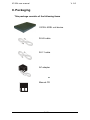
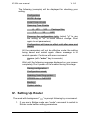
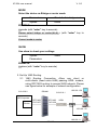
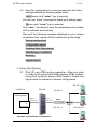
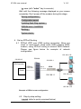
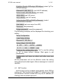
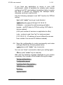
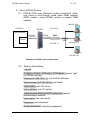
X3102r user manual
V. 2.0
©
Copyright 2002 XAVi Technologies Corporation
All rights reserved.
1 / 33
X3102r user manual
V. 2.0
Chapter 1 : User Guide
I.
Overview ....................................................................................3
II.
Packaging ..................................................................................5
III.
Hardware Installation................................................................7
IV. Management ..............................................................................8
V.
Default Values ...........................................................................9
VI. Software Upgrade ...................................................................10
Appendix A Specifications ............................................................ 11
Appendix B......................................................................................13
B-1 Product Warranty...........................................................13
B-2 FCC Part 15 Notice ........................................................14
B-3 IC CS-03 Notice............................................................. 15
Chapter 2: CLI (Command Line Interface)
Operation
I. Console Set Up: ........................................................................16
II. How to Switch between Bridge and Router ..........................17
III Setting Up a Bridge (RFC 1483 bridge): ................................17
IV. Seting up Router .....................................................................19
1. Set up Router Mdoe .........................................................19
2. Set up 1483 Routing.........................................................20
3. Set up IPoA Routing .......................................................233
4. Set up PPPoA Routing ...................................................266
5. Set up PPPoE Routing .....................................................29
6. Set up DHCP Server Function .........................................31
7. DNS Relay Setting ............................................................33
2 / 33
X3102r user manual
Charpter
I.
1
V. 2.0
User Guide
Overview
X3102r is a 2-Wire SHDSL CPE, complied with PAM16 Line
Code, G.991.2 and G.994.1 standards, and equipped with one
Ethernet switch with 4 * 10/100BaseTX auto-sensing ports. X3102r
SHDSL Router provides a basic Internet access via 10/100Mbps
Ethernet switch and SHDSL WAN port with routing function over
SHDSL.
Features
!
High Speed Symmetrical Data Transmission on one Pairs
of Twisted Copper Wire
!
ITU standard PAM16 Line Code, comply with G.991.2 and
G.994.1 standards
!
Supports Annex.A and Annex.B mode operation
!
Supports Wetting Current range from 0.3mA to 3mA
!
One Ethernet switch with 4 * 10/100Mbps auto-sensing
ports for PC or LAN connection
!
Provide the broad range of Symmetrical Multi-rate Data
Transmission from 72 Kbps up to 2.3 Mbps
!
Supports PPPoE (RFC2516), PPP (RFC2364) and IP
(RFC 2225/RFC1577) over ATM over SHDSL
!
RFC2684 (RFC1483) Bridged/Routed for both LLC/VC
MUX
!
DHCP server supported for easy LAN IP address
management
!
Allows LAN users to access Internet through Network
Address Translation (NAT, IP sharing) simultaneously
3 / 33
X3102r user manual
V. 2.0
!
Local OAM&P through command line interface via RS-232
Craft port
!
Configuration and management by local Telnet, SNMP,
and WEB Browser through the Ethernet interface and
remotely through SHDSL interface
!
Firmware upgradeable through TFTP
!
High performance, simple operation and low power
consumption
4 / 33
X3102r user manual
V. 2.0
II. Packaging
This package consists of the following items
X3102r ADSL unit device
RJ-45 cable
RJ-11 cable
AC adapter
1.
Manual CD
5 / 33
X3102r user manual
V. 2.0
Appearance
Front Panel
ALM: “Blink” while booting up, and “On”
when there is an error.
WAN: “Blink” while training with DSLAM and “On”
when SDSL link is ready
LAN: “On” while one of Ethernet ports is properly
connected to a LAN or PC
ACT: “Blink” while transmitting or receiving packets over one of
Ethernet ports
PWR: “On” while the power supply is properly connected.
Rear Panel
RJ11, SHDSL
Green LED*4; “On” while
corresponding Ethernet port is
connected. “Blink” while
transmitting or receiving packets
RJ45*4, for connection to LAN or PC
DB9, serial port for connection to ASCII data terminal
Power Jack, for connection to an AC-DC power adapter, 12VDC, 1A
6 / 33
X3102r user manual
III.
V. 2.0
Hardware Installation
1. Connect the DSL cable, as (1) indicated, to the LINE port of
RJ-11 socket.
2. Use a RJ-45 cable, as (2) indicated, to connect the X3102r to
the LAN or a PC with Ethernet adapter installed.
3. Use a 9-pin RS-232 cable, as (3) indicated, to connect the
Console Port to a serial port of a terminal such as PC with
data terminal emulation software (Hyper Terminal) installed
for local management if necessary.
4. Plug in the AC adapter to the AC power socket, and then
connect the DC jack, as (4) indicated, to the AC inlet of the
X3102r.
(1)
(4)
(3)
Management Terminal
ADSL Outlet
(2) PC
Note: Be sure to use RJ45 crossover cable while connecting to a hub.
7 / 33
X3102r user manual
IV.
V. 2.0
Management
X3102r supports simple, flexible and easy-to-operate
methods for management purpose. X3102r can be managed via the
following paths. Refer to Appendix B for detailed information.
!
Console Port – use the RS-232 cable for connecting
X3102r to a console terminal or a PC running terminal
emulation program, such as Hyper Terminal, see Appendix
A for proper console setup.
!
Local Ethernet Port – connect the Ethernet port to your
local area network or to a PC directly, “Telnet” X3102 from
any workstation in the LAN. The default local Ethernet IP
address is “192.168.1.1”.
!
SHDSL Port from Remote Site – while SHDSL connection
is in service, you may remotely “Telnet” X3102r from a
workstation networking to the CO equipment.
Note: As operating SHDSL device requires technical know-how and
experience. It is recommended to manage X3102r by qualified
technical staffs only. Therefore a password authentication is applied
when you enter the command line interface, consult your service
provider for obtaining the appropriate password.
8 / 33
X3102r user manual
V.
V. 2.0
Default Values
X3102r is pre-configured with the following parameters; you
may also re-load the default parameters by selecting Default from
the main menu. For hub operation, only half-duplex mode will be
allowed.
Default Mode: Bridge
Factory Password: 0000
Bridge Mode Setting
G.SHDSL Setting
Ethernet (local) IP: 192.168.1.1
Terminal: CPE
Subnet Mask: 255.255.255.0
Rate Mode: Adaptive
Full Duplex: Disable
Annex: Annex B
Protocol: RFC1483, Bridge Mode
VPI/VCI: 8/35
Class (QoS): UBR
Spanning Tree: Disable
Packet Filter: Any
Router Mode Setting
DHCP Server: Disable
Ethernet (local) IP: 192.168.1.1
DNS Relay: Disable
Subnet Mask: 255.255.255.0
Full Duplex: Disable
9 / 33
X3102r user manual
VI.
V. 2.0
Software Upgrade
You may easily upgrade the X3102r embedded software by
obtaining the compressed upgrade kit from the service provider then
following the steps:
Note:
!
Extract the ZIP file for updated firmware.
!
Connect X3102r via the local Ethernet port or remote DSL
link, make sure the X3102r Ethernet IP address and your
terminal are properly configured so that you can
successfully “ping” X3102r The default local IP address is
192.168.1.1.
!
Under DOS prompt, execute command “xupgrade <IP
address of X3102r>”, for instance “xupgrade
192.168.1.1”.
!
This upgrading process might last as long as 60 seconds.
!
Then reboot X3102r with new software.
Strictly maintain stable power to X3102r while upgrading software,
if power failed during the upgrading process, contents in the
memory could be destroyed and the system will hang. In such case
you must call the dealer or system integrator to repair.
10 / 33
X3102r user manual
V. 2.0
Appendix A Specifications
Hardware Specifications
#
Local Interface
•
•
•
#
WAN SHDSL Line Interface
•
•
•
•
•
#
(W x D x H) 224mm x 162mm x 33mm
Power
•
•
#
Temperature: 0°C ~ 45°C
Humidity: 5% ~ 95% Non-condensing
Physical Dimensions
•
#
Local: RS-232 Craft Port or Telnet, Web browser via Ethernet
Remote: SNMP, Telnet or Web browser
Environment
•
•
#
PWR -- Green LED, indicates power and operation
ACT -- Green LED, indicates LAN data Transmitting / Receiving
LINK-- Green LED, indicates LAN data link status
WAN-- Green LED, indicates SHDSL data link status
ALM -- Red LED, indicates data error and operation fault
OAM&P
•
•
#
Data Rate: 72 Kbps up to 2.3Mbps rate adaptive
Line Code: PAM16
Line Impedance: 135 Ω
Connection Loops: One Pair
Connector: RJ-11
Indicators
•
•
•
•
•
#
4 * 10/100BaseTX Ethernet switch, IEEE 802.3u, RJ-45 connectors
10 Half, 10Full, 100Half, 100Full, Auto Negotiation configurable for
each port
Support port-based VLAN
AC Adapter :Input 110VAC/60Hz or 220VAC/50Hz; Output 12VDC
1A
Power Consumption: Less than 10 Watts
Certificates
•
•
EMC: CE EN300386 & FCC Part 15 class B
Safety: EN60950 & CB
11 / 33
X3102r user manual
V. 2.0
Software Specifications
#
•
•
•
•
•
•
#
ATM
ATM Cell over SHDSL, AAL5
Support UBR & CBR & VBR-nrt & VBR-rt
VPI Range (0-4095) and VCI range (1-65535)
Support up to 8 PVCs for bridge and 5 PVCs for router
Support OAM F4/F5 loopback
Payload Encapsulation -− RFC2684 (RFC1483), multi-protocol over ATM
− RFC2225 (RFC1577), IPoA
− RFC2364, PPP over ATM (CHAP and PAP supported)
− RFC2516, PPPoE (PPP over Ethernet) over ATM
Bridging
•
•
•
•
•
Transparent Bridging (IEEE 802.1D)
RFC2684 (RFC1483) Bridged
Spanning Tree Protocol (IEEE 802.1D)
Supporting IP, IGMP and PPPoE packets filter function
Port based VLAN
•
•
•
•
TCP/IP with RIP1, RIP2 or static IP routing
NAT/PAT – RFC1631 (basic Firewall support)
RFC2684 (RFC1483) Routed
DNS Relay
•
•
•
•
•
DHCP server for IP management
Local console configuration and management through RS-232 port
Telnet for local or remote management
TFTP for firmware upgrade and configuration
WEB configuration
#
Routing
#
Configuration and Network Management
12 / 33
X3102r user manual
V. 2.0
Appendix B
Warranties and FCC Regulations
B-1
Product Warranty
1. XAVi Technologies warrants that the ADSL unit will be free
from defects in material and workmanship for a period of
twelve (12) months from the date of shipment.
2. XAVi Technologies shall incur no liability under this
warranty if
- The allegedly defective goods are not returned prepaid
to XAVi Technologies within thirty (30) days of the
discovery of the alleged defect and in accordance with
XAVi Technologies’ repair procedures; or
- XAVi Technologies’ tests disclose that the alleged defect
is not due to defects in material or workmanship.
3. XAVi Technologies’ liability shall be limited to either repair
or replacement of the defective goods, at XAVi
Technologies’ option.
4. XAVi Technologies MARKS NO EXPRESS OR IMPLIED
WARRANTIES
REGARDING
THE
QUALITY,
MERCHANTABILITY, OR FITNESS FOR A PARTICULAR
PURPOSE BEYOND THOSE THAT APPEAR IN THE
APPLICABLE USER’S DOCUMETATION. XAVi SHALL
NOT BE RESPONSIBLE FOR CONSEQUENTIAL,
INCIDENTAL, OR PUNITIVE DAMAGE, INCLUDING, BUT
NOT LIMITED TO, LOSS OF PROFITS OR DAMAGES TO
BUSINESS
OR
BUSINESS
RELATIONS.
THIS
WARRANTY IS IN LIEU OF ALL OTHER WARRANTIES.
Warranty Repair
1.
During the first three (3) months of ownership, XAVi
Technologies will repair or replace a defective product
covered under warranty within twenty-four (24) hours of
receipt of the product. During the fourth (4th) through
twelfth (12th) months of ownership, XAVi Technologies will
13 / 33
X3102r user manual
V. 2.0
repair or replace a defective product covered under
warranty within ten (10) days of receipt of the product. The
warranty period for the replaced products shall be ninety
(90) days or the remainder of the warranty period of the
original unit, whichever is greater. XAVi Technologies will
ship surface freight. Expedited freight is at customer’s
expense.
2. The customer must return the defective product to XAVi
Technologies within fourteen (14) days after the request for
replacement. If the defective product is not returned within
this time period, XAVi Technologies will bill the customer for
the product at list price.
Out-of Warranty Repair
XAVi Technologies will either repair or, at its option, replace a
defective product not covered under warranty within ten (10)
working days of its receipt. Repair charges are available from
the Repair Facility upon request. The warranty on a serviced
product is thirty (30) days measured from date of service.
Out-of-warranty repair charges are based upon the prices in
effect at the time of return.
B-2 FCC Part 15 Notice
Warning: This equipment has been tested and found to comply
with the limits for a Class B digital device, pursuant to Part 15
to the FCC rules. These limits are designed to provide
reasonable protection against harmful interference when the
equipment is operated in a residential environment. This
equipment generates, used, and can radiate radio frequency
energy, and, if not installed and used in accordance with the
instruction manual, may cause harmful interference to radio
communications. Operation of this equipment in a residential
area is unlikely to cause harmful interference. But if it does, the
user will be required to correct the interference at his or her
own expense. The authority to operate this equipment is
conditioned by the requirement that no modifications will be
made to the equipment unless XAVi expressly approves the
changes or modifications.
14 / 33
X3102r user manual
B-3
V. 2.0
IC CS-03 Notice
The Industry Canada label identifies certified equipment. This
certification means that the equipment meets certain
telecommunications network protective, operational, and safety
requirements as prescribed in appropriate Terminal Equipment
Technical Requirements document(s). The Department does
not guarantee that the equipment will operate to the user’s
satisfaction.
Before installing this equipment, users should make sure that it
is permissible to be connected to the facilities of the local
telecommunications company. An acceptable method of
connection must be used to install the equipment. The
customer should be aware that compliance with the above
conditions might not prevent degradation of service in some
situations.
Repairs to certified equipment should be coordinated by a
representative designated by the supplier. Any repairs or
alterations made by the user to this equipment, or equipment
malfunctions, may give the telecommunications company
cause to request the user to disconnect the equipment.
Users should ensure for their own protection that the electrical
ground connections of the power utility, telephone lines, and
internal metallic water pipe system, if present, are connected
together. This precaution may be particularly important in rural
areas.
Warning: Users should not attempt to make such connections
themselves, but should contact appropriate
inspection authority, or electrician, as appropriate.
15 / 33
electric
X3102r user manual
Charpter
2
V. 2.0
CLI Operation
I. Console Set Up:
Connect the RS-232 Console port to an ASCII data terminal or a
PC with Widows serial Terminal mode of VT-100 (Hyper Terminal). To
Start the Hyper-terminal, following the steps below:
1.
Start "Hyper-terminal" program -On Windows 98 or Windows NT:
Start Tool Bar $ Program $ Accessory $ Hyper Terminal Group $
Double Click “Hypertrm.exe” $ Enter “Connection Name” $
Select Icon $ Click “OK”
2.
Select COM port to communicate with XAVi modem
Choose direct to COM1 or COM2 % click OK
3.
!
Set Port Properties -Port Setting:
− Bit per second: 9600
− Data bits: 8
− Stop bits: 1
− Parity bits: None
− Flow Control: None
!
Settings:
− Function, arrow, and ctrl keys act as: Windows keys
− Emulation: Auto-detect
− Back-scroll buffer lines: 500
!
ASCII Setup:
−
Echo typed characters locally
16 / 33
X3102r user manual
V. 2.0
−
Line delay: 0 milliseconds
−
Character line feeds incoming line ends: enable
II. How to Switch between Bridge and Router
Please see the command below for detailed command setting.
MODE
Select the device as Bridge or router mode
Syntax:
Mode
Parameters:
The default is bridge mode.
Example:
>>mode
The word with background “
command
“ is prompt following by a
>> mode (with “enter” key to execute)
Please select bridge or router:(b/r,b) r (with “enter” key to
execute)
Current mode is router
III. Setting up a Bridge (RFC 1483 bridge)
1. If you are in Router mode, use “mode” command to switch to
Bridge mode before setting parameters.
MODE
Select the device as Bridge or Router mode
Syntax:
Mode
Parameters:
The default is bridge mode.
Example:
>>mode
The word with background “
command.
17 / 33
“ is prompt following by a
X3102r user manual
V. 2.0
EXAMPLE
>>mode (with “enter” key to execute)
Please select bridge or router: (b/r,r) b (with “enter” key to
execute)
Current mode is bridge.
2. Set Up RFC 1483 Bridge
2.1 RFC1483 bridging connection. Allow only one client
passing ADSL modem to access WAN network. Please
see figure below for example of network configuration
DSLAM
ISP/Corporate
RFC1483
PVC 8/36
RFC1483
PVC 8/35
XDSL Modem
Bridge
Router
Example for RFC 1483 bridge configuration
2.2 Step by Step Setting
>>quick (with “enter” key to execute)
VPI(0-1023): (setting VPI value)
VCI(1-65535): (setting VCI value)
Packet Filter (Any/Ip/Pppoe+IGMP): (set filtering function
to allow specific packet type passing through modem.
“Any” for without filtering)
Add another PVC? (y/n): (set another PVC with “y” or
“N” to complete PVC setting)
Enable Spanning tree? (y/n): (set Spanning tree “y” for
enable)
18 / 33
X3102r user manual
V. 2.0
The following (example) will be displayed for checking your
setting.
Configuration
MODE: Bridge
FUNCTION: R1483
Spanning Tree: Enable
# VPI
1: 2
VCI
34
Package filter
ANY
Preserve the configuration (y/n): (select “y” to use
the setting or “n” to leave without change. Start
again to set parameters)
Configuration will have no effect until after save and
restart.
All the parameters will not be effective under the setting
being saved and restart again. Above message is to
remind operator. Continue with save command
>>save (with “enter” key to execute)
Wait until the following message displayed on your screen
completely. Don’t power off the modem during this stage.
Saving configuration...
Configuration saved.
Updating flash filing system ...
SDRAM size = 0x800000
Booting...
System starts...
IV. Setting Up Router
The word with background “
“ is prompt following by a command.
1. If you are in Bridge mode use “mode” command to switch to
Router mode before setting parameters.
19 / 33
X3102r user manual
V. 2.0
MODE
Select the device as Bridge or router mode
Parameters:
The default is bridge mode.
Syntax:
mode
EXAMPLE
>>mode (with “enter” key to execute)
Please select bridge or router:(b/r,b) r (with “enter” key to
execute)
Current mode is router
SHOW
Use show to check your settings
Syntax:
Show
Parameters:
EXAMPLE
>>show (with “enter” key to execute)
2. Set Up 1483 Routing
2.1 1483 Routing Connection. Allow one client or
multi-clients (need extra HUB) passing ADSL modem,
using RFC1483 routing to access WAN network. Please
see figure below for example of network configuration
192.168.1.50
DSLAM
210.62.8.2
210.62.8.1
PC1
ISP/Corporate
Router
RFC1483
PVC 8/37
RFC1483
PVC 8/36
XDSL
HUB
PC2
192.168.1.51
192.168.1.1
20 / 33
PC3
X3102r user manual
V. 2.0
2.2 Step by Step Setting
>>quick (with “enter” key to execute)
R1483(r)/ IPoA(i)/ PPPoA(p)/ PPPoE(pe): (select “r” for
1483 routing)
Ethernet IP (192.168.1.1): (set LAN IP address)
Subnet Mask (255.255.255.0): (set mask)
VPI(0-1023): (set VPI value)
VCI(1-65535): (set VCI value)
WAN IP: (set WAN IP address)
Add another PVC? (y/n): (set another PVC with “y” or
“n” to complete PVC setting)
The following (example) will be displayed for checking your
setting.
Configuration
MODE: Router
FUNCTION: R1483
Ethernet IP: 192.168.1.1
Subnet Mask: 255.255.255.0
# VPI
VCI
WAN IP
1: 8
32
192.168.1.2
Preserve the configuration (y/n): (“y” to use the setting
or “n” to leave without change. Start again to set
parameters)
Configuration will have no effect until after save and
restart.
All the parameters will not be effective under the setting
being saved and restart again. Above message is to remind
operator.
21 / 33
X3102r user manual
V. 2.0
2.3 NAT function
This function will enable PC users in your LAN
environment to access outside with only one IP address (IP
sharing) and one access account. Use the following example
to enable NAT function for RFC1483 routing.
>pat (with “enter” key to go to pat director)
>pat>setpat 192.168.1.2 enable
(Enable NAT function for RFC1483 routing for specific WAN
IP address. Replace WAN IP address with the specific
address set for RFC1483 routing in this example. You have
to repeat this command if more than one PVC had been
configured)
Note:
1.
The same command with “disable” attribute to disable NAT
function.
2.
If you have any application or server in your LAN environment
which is available for outside uses, please configure the PAT
(port address translation) table to enable this kind of service by
following the example below, otherwise continue to section 4.2.4
Use the following example to set PAT table for RFC1483
routing.
>pat>addpatin 192.168.1.2 434/udp 210.18.35.10
(Addpatin – command for add incoming pat table)
(192.168.1.2 – WAN IP address of RFC1483 routing.
Replaced with specific WAN IP address set for RFC1483
routing in this example. PAT table is service related)
(434- port number of services or application to offer)
(udp – protocol used. Use ”tcp” for tcp/ip services)
(210.18.35.10 – IP address of server offered for access
from outside. Use correct IP Address instead)
22 / 33
X3102r user manual
V. 2.0
2.4 Save the configuration to router permanently and make
settings effective by following steps below
>pat> home (with “enter” key to execute)
You can use “show” command to check your setting again.
>>save (with “enter” key to execute)
Use “save” command to save the parameters and modem
will be restarted automatically.
Wait until the following message displayed on your screen
completely. Don’t power off the modem during this stage.
Saving configuration
Configuration saved
Updating flash filing system
SDRAM size = 0x800000
Booting...
System starts...
3. Set up IPoA Routing
3.1 IPoA (IP over ATM) routing connection. Allow one client
or multi-clients (need extra HUB) passing ADSL modem,
using IPoA routing to access WAN network. Please see
figure below for example of network configuration.
192.168.1.50
DSLAM
210.62.8.2
210.62.8.1
PC1
ISP/Corporate
IPoA
PVC 8/37
IPoA
PVC 8/36
XDSL
R
HUB
192.168.1.1
PC2
192.168.1.51
Example of IPoA Router Configuration
23 / 33
PC3
192.168.1.52
X3102r user manual
V. 2.0
3.2 Step by Step Setting
>> quick
R1483(r)/ IPoA(i)/ PPPoA(p)/ PPPoE(pe): (select “i” for
IPoA routing)
Ethernet IP (192.168.1.1): (set LAN IP address)
Subnet mask (255.255.255.0): (set mask)
VPI(0-1023): (set VPI value)
VCI(1-65535): (set VCI value)
WAN IP: (set WAN IP address)
Gateway : (set Gateway IP address)
Add another PVC? (y/n): (set another PVC with “y” or
“n” to complete PVC setting)
The following (example) will be displayed for checking your
setting
Setup Configuration
FUNCTION: IPOA
Ethernet IP: 192.168.1.1
Subnet Mask: 255.255.255.0
# VPI
VCI
WAN IP
1: 5
45
192.168.1.3
Gateway IP
192.168.1.10
Preserve the configuration (y/n): (“y” to use the setting
or “n” to leave without change. Start again to set
parameters)
Configuration will have no effect until after save and
restart.
All the parameters will not be effective under the setting
being saved and restart again. Above message is to remind
operator
3.3 NAT function
This function will enable PC users in your LAN environment
to access outside with only one IP address (IP sharing) and
one access account.
24 / 33
X3102r user manual
V. 2.0
Use the following example to enable NAT function for IPoA
routing.
>pat ( with “enter” key to go to pat director)
>pat>setpat 192.168.1.3 enable
>pat>setpat 192.168.1.3 enable
(Enable NAT function for IPoA routing for specific WAN IP
address. Replace WAN IP address with the specific
address set for IPoA routing in this example. You have to
repeat this command if more than one PVC had been
configured)
(Use the same command with “disable” attribute to disable
NAT function)
If you have any application or server in your LAN
environment, which is available for outside uses, please
configure the PAT (port address translation) table to enable
this kind of service by following the example below,
otherwise continue to section 3.4
Use the following example to add PAT table for IPoA
routing. The word with background “ “ is prompt following
by a command required
>pat> addpatin 192.168.1.3 434/udp 210.18.35.10
(Addpatin – command for add incoming pat table)
(192.168.1.3 – WAN IP address of IPoA routing.
Replaced with specific WAN IP address set for IPoA
routing in this example. PAT table is service related)
(434- port number of services or application to offer)
(udp – protocol used. Use ”tcp” for tcp/ip services)
(210.18.35.10 – IP address of server offered for access
from outside. Use correct IP Address instead)
3.4
Save the configuration to router permanently and make
settings effective by following steps below
>pat> home (with “enter” key to execute)
You can use “show” command to check your setting again.
25 / 33
X3102r user manual
V. 2.0
>> save (with “enter” key to execute)
Wait until the following message displayed on your screen
completely. Don’t power off the modem during this stage.
Saving configuration...
Configuration saved.
Updating flash filing system ...
SDRAM size = 0x800000
Booting...
System starts...
4 Set up PPPoA Routing
4.1 PPPoA (PPP over ATM) routing connection. Allow one
client or multi-clients (need extra HUB) passing ADSL
modem, using PPPoA routing to access WAN network.
Please see figure below for example of network
configuration.
192.168.1.50
DSLAM
210.62.8.2
210.62.8.1
PC1
ISP/Corporate
PPPoA
PVC 8/37
PPPoA
PVC 8/36
XDSL
Router
HUB
192.168.1.1
PC2
192.168.1.51
PC3
192.168.1.52
Example of PPPoA router configuration
4.2 Step by step setting:
>>quick (refer to quick command below)
26 / 33
X3102r user manual
V. 2.0
R1483(r)/ IPoA(i)/ PPPoA(p)/ PPPoE(pe): (select “p” for
PPPoA routing)
Ethernet IP (192.168.1.1): (set LAN IP address)
Subnet mask (255.255.255.0): (set mask)
VPI(0-1023): (set VPI value)
VCI(1-65535): (set VCI value)
Authentication(PAP(p)/CHAP(c)/None(n)): (select
authentication method)
User name: (set user name from ISP)
Password: (set password)
Retype password: (reconfirm password)
The following (example) will be displayed for checking your
setting
Setup Configuration
FUNCTION: PPPOA
Ethernet IP: 192.168.1.1
Subnet Mask: 255.255.255.0
# VPI
VCI
AUTH
USERID
1: 7
34
CHAP
xavi
Preserve the configuration (y/n): (“y” to use the setting
or “n” to leave without change. Start again to set
parameters)
Configuration will have no effect until after save and
restart.
All the parameters will not be effective under the setting
being saved and restart again. Above message is to remind
operator.
4.3 NAT function
NAT function will be enabled automatically when PPPoA
routing set. This function will enable PC users in your LAN
environment to access outside with only one IP address (IP
sharing) and one access account.
27 / 33
X3102r user manual
V. 2.0
If you have any application or server in your LAN
environment, which is available for outside uses, please
configure the PAT (port address translation) table to enable
this kind of service by following the example below,
otherwise continue to section 4.4
Use the following example to set NAT function for PPPoA
routing.
>pat (with “enter” key to go to pat director)
>pat> addpatin pppoa 434/udp 210.18.35.10
(Addpatin – command for add incoming pat table)
(pppoa – set PAT table for PPPoA routing. PAT table is
service related)
(434- port number of services or application to offer)
(udp – protocol used. Use ”tcp” for tcp/ip services)
(210.18.35.10 – IP address of server offered for access
from outside. Use correct IP Address instead)
4.4 Save the configuration to router permanently and make
settings effective by following steps below.
>pat> home (with “enter” key to execute)
You can use “show” command to check your setting again.
>>save (with “enter” key to execute)
Wait until the following message displayed on your screen
completely. Don’t power off the modem during this stage.
Saving configuration...
Configuration saved.
Updating flash filing system ...
SDRAM size = 0x800000
Booting...
System starts...
28 / 33
X3102r user manual
V. 2.0
5 Set up PPPoE Routing
5.1 PPPoE (PPP over Ethernet) routing connection. Allow
one client or multi-clients (need extra HUB) passing
ADSL modem, using PPPoE routing to access WAN
network.
192.168.1.50
210.62.8.2
210.62.8.1
DSLAM
PC1
ISP/Corporate
PPPoE
PVC 8/37
PPPoE
PVC 8/36
XDSL
Router
HUB
192.168.1.1
PC2
192.168.1.51
PC3
192.168.1.52
Example of PPPoE router configuration
5.2 Step by Step Setting
>>quick
R1483(r)/ IPoA(i)/ PPPoA(p)/ PPPoE(pe): (select “pe”
for PPPoE routing)
Ethernet IP (192.168.1.1): (set LAN IP address)
Subnet mask (255.255.255.0): (set mask)
VPI(0-4095): (set VPI value)
VCI(1-65535): (set VCI value)
Authentication(PAP(p)/CHAP(c)/None(n)):(select
authentication method)
User name: (set user name)
Password: (set password)
Retype password: (reconfirm password)
29 / 33
X3102r user manual
V. 2.0
The following (example) will be displayed for checking your
setting
Setup Configuration
FUNCTION: PPPOE
Ethernet IP: 192.168.1.1
Subnet Mask: 255.255.255.0
# VPI
VCI
AUTH
USERID
1: 8
40
PAP
xavi
Preserve the configuration (y/n): (“y” to use the setting
or “n” to leave without change. Start again to set
parameters)
Configuration will have no effect until after save and
restart.
All the parameters will not be effective under the setting
being saved and restart again. Above message is to remind
operator
5.3 NAT function
NAT function will be enabled automatically when PPPoE
routing set. This function will enable PC users in your LAN
environment to access outside with only one IP address (IP
sharing) and one access account.
If you have any application or server in your LAN
environment, which is available for outside uses, please
configure the PAT (port address translation) table to enable
this kind of service by following the example below,
otherwise continue to section 5.4
Use the following example to set NAT function for PPPoE
routing.
>pat (with “enter” key to go to pat director)
>pat>addpatin pppoa 434/udp 210.18.35.10
(Addpatin – command for add incoming pat table)
(pppoe – set PAT table for PPPoE routing. PAT table is
service related)
30 / 33
X3102r user manual
V. 2.0
(434- port number of services or application to offer)
(udp – protocol used. Use ”tcp” for tcp/ip services)
(210.18.35.10 – IP address of server offered for access
from outside. Use correct IP Address instead)
5.4 Save the configuration to router permanently and make
settings effective by following steps below
>pat> home (with “enter” key to execute)
You can use “show” command to check your setting
again.
>>save (with “enter” key to execute)
Wait until the following message displayed on your screen
completely. Don’t power off the modem during this stage.
Saving configuration...
Configuration saved.
Updating flash filing system ...
SDRAM size = 0x800000
Booting...
System starts...
6 Set Up DHCP Server Function
The DHCP server function allows hosts (PCs, etc.) to get IP
address and DNS server address from the router
automatically.
User has to set DHCP client on the computer required for
automatic IP assignment and turn off (close) DNS function on
the PC.
The DHCP server should be in the same subnet with LAN
IP address. Refer to the LAN IP address set for the routing
function (RFC1483 or IPoA or PPPoA or PPPoE) previously.
6.1
Following example to set DHCP configuration
>lan (with “enter” key to execute, same for all
31 / 33
X3102r user manual
V. 2.0
commands)
>lan>dhcpserver
192.168.1.1
192.168.1.10
192.168.1.20 192.168.1.30
(There are two range of IP segment allowed for DHCP
server. Both segment must be in the same subnet with LAN
IP address. Refer to the LAN IP address set for the routing
function (RFC1483 or IPoA or PPPoA or PPPoE) previously.
For example 192.168.1.1 – start IP address of segment 1;
192.168.1.10 – end IP address of segment 1;
192.168.1.20 – start IP address of segment 2;
192.168.1.30 – end IP address of segment 2)
Continue setting up DNS server address for assigning to
PC.
>lan>dhcpserver dns 210.65.18.1 210.65.18.20
(There are two DNS server address could be assigned – for
example 210.65.18.1 and 210.65.18.20. Your service
provider (ISP) should give you those address when you
subscribed service. Use them as right IP address)
6.2
Save the configuration to router permanently and make
settings effective by following steps below
>lan> home (with “enter” key to execute)
You can use “show” command to check your setting again.
>>save (with “enter” key to execute)
Wait until the following message displayed on your screen
completely. Don’t power off the modem during this stage.
Saving configuration...
Configuration saved.
Updating flash filing system ...
SDRAM size = 0x800000
Booting...
System starts...
32 / 33
X3102r user manual
V. 2.0
7 DNS (Domain name server) Relay Setting
The DNS relay function allows DNS request to be
terminated in the router.
To make this function effective, the DNS address on PCs
should be set to the LAN IP address of router. Refer to the LAN
IP address set for the routing function (RFC1483 or IPoA or
PPPoA or PPPoE) previously.
7.1
Following below example to set DNS relay configuration.
>>dnsrelay ( with “enter” key to execute)
>dnsrelay>setdnsip 192.168.8.1
(Your service provide (ISP) should give you DNS address
when you subscribed service. Use it as right IP addresses.
192.168.8.1 is just example)
7.2
Save the configuration to router permanently and make
settings effective by following steps below
>dnsrelay>home (with “enter” key to execute)
You can use “show” command to check your setting again.
>>save (with “enter” key to execute)
Wait until the following message displayed on your screen
completely. Don’t power off the modem during this stage.
Saving configuration...
Configuration saved.
Updating flash filing system ...
SDRAM size = 0x800000
Booting...
System starts...
33 / 33