1
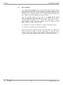
FC Series
Intelligent
Stepper Motor Stages
Controller GUI Manual
Version 1.0.x
For Motion, Think Newport™
FC Series
Controller GUI Manual
Preface
Confidentiality & Proprietary Rights
Reservation of Title
The Newport Programs and all materials furnished or produced in connection with them
("Related Materials") contain trade secrets of Newport and are for use only in the
manner expressly permitted. Newport claims and reserves all rights and benefits
afforded under law in the Programs provided by Newport Corporation.
Newport shall retain full ownership of Intellectual Property Rights in and to all
development, process, align or assembly technologies developed and other derivative
work that may be developed by Newport. Customer shall not challenge, or cause any
third party to challenge, the rights of Newport.
Preservation of Secrecy and Confidentiality and Restrictions to Access
Customer shall protect the Newport Programs and Related Materials as trade secrets of
Newport, and shall devote its best efforts to ensure that all its personnel protect the
Newport Programs as trade secrets of Newport Corporation. Customer shall not at any
time disclose Newport's trade secrets to any other person, firm, organization, or
employee that does not need (consistent with Customer's right of use hereunder) to
obtain access to the Newport Programs and Related Materials. These restrictions shall
not apply to information (1) generally known to the public or obtainable from public
sources; (2) readily apparent from the keyboard operations, visual display, or output
reports of the Programs; (3) previously in the possession of Customer or subsequently
developed or acquired without reliance on the Newport Programs; or (4) approved by
Newport for release without restriction.
©2013 Newport Corporation
1791 Deere Ave.
Irvine, CA 92606, USA
(949) 863-3144
EDH0341En1011 – 11/13
ii
FC Series
Controller GUI Manual
Table of Contents
Preface ..............................................................................................................................ii
1.0
Introduction ............................................................................................. 1
1.1
Purpose ............................................................................................................................. 1
1.2
Overview .......................................................................................................................... 1
1.3
Controller State Diagram .................................................................................................. 2
2.0
2.1
2.2
Getting Started ........................................................................................ 3
Overview and Setup.......................................................................................................... 3
2.1.1
Components ........................................................................................................... 3
2.1.2
Electrical Installation ............................................................................................. 4
First Connection ............................................................................................................... 5
2.2.1
FC Series USB Driver Installation on Windows 7 ................................................ 5
2.2.2
FC Series USB Driver Installation on Window XP............................................... 6
2.3
USB Driver Installation Verification ................................................................................ 8
2.4
Discover Instruments ........................................................................................................ 8
3.0
User Interface ........................................................................................ 10
3.1
Configuration .................................................................................................................. 10
3.2
Main................................................................................................................................ 12
3.3
Parameters ...................................................................................................................... 14
3.4
Address ........................................................................................................................... 15
3.4.1
Controller pool setting ......................................................................................... 16
3.4.2
Controller address setting .................................................................................... 18
3.4.3
Daisy-chaining .................................................................................................... 19
3.5
Diagnostics ..................................................................................................................... 20
3.6
About .............................................................................................................................. 21
Service Form ........................................................................................................ 23
iii
EDH0341En1011 – 11/13
FC Series
EDH0341En1011 – 11/13
Controller GUI Manual
iv
FC Series
Controller GUI Manual
FC Series
Intelligent Stepper Motor Stages
1.0
Introduction
1.1
Purpose
The purpose of this document is to provide instructions on how to use the
FC Series Controller GUI.
1.2
Overview
The FC Series GUI is a graphical user interface (GUI) which allows the user to interact
with the controller that is integrated with intelligent stepper motor stages. The user can
initiate moves, change the state of the controller, adjust configuration parameters, etc.
Communication with the FC series is achieved via an RS-422 serial link and a USB to
RS422 adaptor. The provided GUI requires USB communication interface, based on
WindowsTM operating system. Advanced programming is simplified by an ASCII
command interface and a set of two letter mnemonic commands.
EDH0341En1011 – 11/13
1
FC Series
Controller GUI Manual
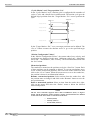
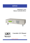
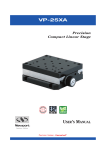
1.3
Controller State Diagram
The FC series controller is defined by the following state diagram.
Actions in each state when End of Runs is encountered
NOT REFERENCED: No action.
CONFIGURATION: No action.
HOMING:
Only check at end of HOMING and then change to
NOT REFERENCED state.
MOVING:
Abort motion and then change to NOT
REFERENCED state.
READY:
Change to NOT REFERENCED state.
DISABLE:
Change to NOT REFERENCED state.
EDH0341En1011 – 11/13
2
FC Series
2.0
Controller GUI Manual
Getting Started
2.1
Overview and Setup
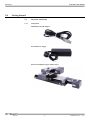
2.1.1
Components
USB-RS422-1.8 USB Adaptor
FC-PS40 Power Supply
FC Series Intelligent Stepper Motor Stages
3
EDH0341En1011 – 11/13
FC Series
Controller GUI Manual
2.1.2
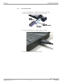
Electrical Installation
1. Connect the USB-RS422-1.8 adaptor cable to the FC series stage.
2. Connect the FC-PS40 power supply to the FC series stage.
3. Connect the USB cable to an available USB port of the PC
4. Connect the power cable to an electrical outlet.
EDH0341En1011 – 11/13
4
FC Series
Controller GUI Manual
2.2
First Connection
CAUTION
BEFORE ANY INSTALLATION, CONTACT YOUR I.T. ADMINISTRATOR TO
VERIFY THAT YOU HAVE THE APPROPRIATE RIGHTS.
2.2.1
FC Series USB Driver Installation on Windows 7
1. Connect the FC Series controller to a USB port with the provided USB cable.
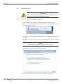
2. Detection of this new connected device (the first time) is signaled by a message in
the bottom-right of the screen.
3. For Windows 7 64 bit, the USB driver installation is completed when the message
disappears.
4. For Windows 7 32 bits, right click on the new detected device and select “Update
driver”.
NOTE
Automatic driver installation requires internet connection.
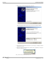
Click “Search automatically for updated driver software”.
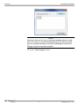
5. The following window will pop up after driver installation is completed.
5
EDH0341En1011 – 11/13
FC Series
Controller GUI Manual
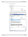
2.2.2
FC Series USB Driver Installation on Window XP
1. Download FC_USB_RS422_driver from newport.com
2. Run the executable file included.
EDH0341En1011 – 11/13
6
FC Series
Controller GUI Manual
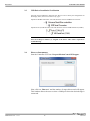
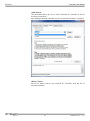
3. Select “Extract” and the following window will pop up.
The following page indicates that the drivers have been successfully installed.
4. Once the drivers are installed connect the FC series stage to a USB port with the
USB-RS422-1.8 cable.
5. Detection of this new connected device (the first time) is signaled by a message in
the bottom -right of the screen.
Now, your FC series is installed and ready to use.
7
EDH0341En1011 – 11/13
FC Series
Controller GUI Manual
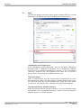
2.3
USB Driver Installation Verification
Open the “Device Manager” and select the “Device” tab to check your configuration. In
the display menu, select “View devices by type”.
Expand “USB Bus controllers” line and check the new line USB Serial Converter:
Expand “Ports (COM and LPT)” line and check the new line USB Serial Port (COMx):
NOTES
Note the COM port number (x) assigned to the device. This will be required for
troubleshooting.
2.4
Discover Instruments
Start the Controller GUI from Newport\MotionControl\FCStepper.
Next, click on “Discover” and the number of stages discovered will appear.
This window allows the user to select a COM port where the desired stage is
connected.
EDH0341En1011 – 11/13
8
FC Series
Controller GUI Manual
NOTE
When more than one FC stage is connected, multiple instances of this
GUI can be open to control each individual stage. To discern a COM
port for a specific instrument, note their COM number in the Device
Manager when the connection is added.
Next, click “Launch Applet” button.
9
EDH0341En1011 – 11/13
FC Series
3.0
Controller GUI Manual
User Interface
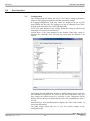
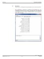
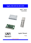
3.1
Configuration
The Configuration tab allows the user to view and/or change information
related to the logging configuration and the instrument settings.
In LoggingConfiguration, read only values are displayed for the log file
name and the log file path. The logging level may be changed to any of the
settings in the drop-down list on the right hand side.
Trace is the most detailed of the settings. When this setting is selected, the
Controller GUI logs all the information.
Critical Error is the least detailed of the settings. When this setting is
selected, the Controller GUI will only log errors that are defined to be
critical.
The polling interval defines the number of milliseconds between each time
the Controller GUI polls the FC series for the latest information. The user
may change the polling interval by entering a value. Diagnostics Delay
defines the time delay in milliseconds between each command sent from a
text file.
InstrumentType and NoOfInstruments display the name and number of
connected instruments.
The Save button allows the user to save the current settings to the
configuration file.
EDH0341En1011 – 11/13
10
FC Series
Controller GUI Manual
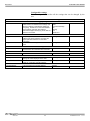
Configurable settings
The following table describes all the settings that can be changed by the
user.
Parameter
Level
PollingInterval
NbDigits
Delay
CommunicationChannel
BufferDepth
RollingBuffer
ControllerAddress
Description
Values / Type
Default
LoggingConfiguration
Logging level.
Trace is the most detailed of the settings and
when this setting is selected the applet logs
everything. Critical Error is the least detailed
of the settings and when this setting is
selected the applet will only log errors that are
defined to be critical.
Trace
Detail
Equipment Message
Info
Warning
Error
Critical Error
Trace
InstrumentInformation
The polling interval defines the number of
An Integer
milliseconds (delay) between each time the
applet polls the instrument for the latest
information.
Number of fractional digits after the decimal
An Integer
point.
Diagnostics
The delay defines the number of milliseconds
between each sent command from a text file.
Models\InstrumentInfo
The communication channel
RS232
MemorizedPosition
BufferDepth defines the maximum number of
An Integer
analog I/O values displayed in the chart.
The list of the memorized position in the rolling A String
buffer for a selected controller address
SelectedAxis
List of the selected controller address.
A String
11
200
6
RS232
5
EDH0341En1011 – 11/13
FC Series
Controller GUI Manual
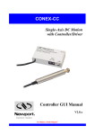
3.2
Main
The Main tab displays the main controls in the Controller GUI like a virtual
front panel. It is updated each time the polling interval timer expires.
“Initialization and Configuration”
In the “Initialization and Configuration” area, the first button changes the
controller status to “Enabled” or "Disabled” To see the different controller
states, refer to the controller state diagram in section 1.3. The second button
“Save Pos.” memorizes the current position in the combo box. As soon as a
new position is memorized, this is displayed in the trace.
“Current Position”
In the “Current Position” area, the current position is displayed in a text box
and visualized in a slider. The slider limits are defined with the ends of run.
An LED icon shows the current controller state. When the mouse hovers
over the icon, the controller state is displayed in an information balloon.
“Incremental Motion / PR-Move Relative”
In the “Incremental Motion / PR-Move Relative” area, two increment values
can be defined. For each defined increment, a relative move is performed in
either the negative or positive direction.
EDH0341En1011 – 11/13
12
FC Series
Controller GUI Manual
“Cyclic Motion” and “Target position / PA”
In the “Cyclic Motion” area, a motion cycle is configured with a number of
cycles (Cycle) and a dwell time in milliseconds. The motion cycle gets the
defined target positions from the “Target Motion / PA” area to perform the
cycle.
Target #2
Target #1
Tempo (Dwell)
Loop #1
Tempo (Dwell)
Tempo (Dwell)
Loop #2
Tempo (Dwell)
Loop #N
In the “Target Motion / PA”” area, two target positions can be defined. The
“Go to” button executes the absolute move to go to the specified target
position.
“Motion Configuration Values”
In the “Motion Configuration Values”, the current ends of run, velocity, and
acceleration are displayed in this area: “Minimum end of run”, “Maximum
end of run”, “Acceleration”, and “Velocity” can be modified and saved with
the “Set” button.
Memorized positions
The combo box memorizes the positions set by the “Save Pos.” button. Each
of these positions can be renamed or deleted. To execute an absolute move
to one of these memorized positions, select one item of the combo box and
click on the “Go to” button. When the mouse moves over to the combo box,
the position is shown in an information balloon.
Rename a memorized position: Select an item from the combo box, edit
the position name to change it and click on the “Rename” button to save the
new position name.
Delete a memorized position: Select an item from the combo box, rightclick on the mouse and select the “Delete” menu to delete the selected
memorized position.
NOTE
The FC series controller supports native units of millimeter (FCL) or degrees
(FCR). All the parameters such as position, velocity and acceleration are defined
on the same scale. These units are not shown in the GUI.
•
Position (Units)
•
Velocity (Units/s)
•
Acceleration (Units/s2)
13
EDH0341En1011 – 11/13
FC Series
Controller GUI Manual
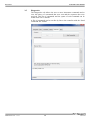
3.3
Parameters
The Parameters tab displays the stage parameters for the selected controller.
Note modification of parameters is disabled in the Parameters tab. User
configuration parameter such as velocity, acceleration and End of Runs can
be changed in the main tab. Other configuration parameters can be modified
in the diganostics tab by using the commands. Refer to user’s manual for
details of the commands.
EDH0341En1011 – 11/13
14
FC Series
Controller GUI Manual
3.4
Address
The Address tab allows the followings:
1) To scan and select connected FC series controllers.
2) To configure the controller address
15
EDH0341En1011 – 11/13
FC Series
Controller GUI Manual
3.4.1
Controller pool setting
“Discover” button
The Discover button scans to detect connected FC controllers (address #1 to
address #4).
After a Discover action, the list of detected controllers is filled. Stage model
number is shown next to the address #1 through #4. This address helps to
identify each controller connected.
EDH0341En1011 – 11/13
16
FC Series
Controller GUI Manual
“Add” button
The Add button allows the user to add a connected FC controller to the list
of selected controllers.
After adding a detected controller, the list of selected controllers is updated.
“Delete” button
The Delete button removes the selected FC controller from the list of
selected controllers.
17
EDH0341En1011 – 11/13
FC Series
Controller GUI Manual
3.4.2
Controller address setting
This part allows the user to configure the address of the FC controller.
“Set” button
Select a controller address from the list and press the “Set” button. A
progress bar is displayed during the address configuration.
Now disconnect this controller from your PC and connect the next one.
Select a new, unallocated address and press the “Set” button again (proceed
the same way with all other controllers).
EDH0341En1011 – 11/13
18
FC Series
Controller GUI Manual
3.4.3
Daisy-chaining
Up to 4 FC series controllers can be networked through the internal RS232
communications link. Before daisy-chaining, the controller address of each
stage must be set separately. The FC controller that will be connected to the
PC must have its controller address set to 1 and all subsequent stages must
have a different controller address set between 2 and 4.
Once the controller address of each stage is set, unplug all the power
cables and disconnect the USB cable from all the stages except for the FC
controller that has its address set to 1. Use the daisy chain cables to connect
each controller. It does not matter whether you use the upper or lower
RS422 connector to daisy chain the stages.
• Only the FC controller with address 1 should be connected to the PC
• All other FC controllers must be daisy-chained.
Plug in all the power supplies and open the GUI. Under the Address tab
select the Discover button to scan for connected FC’s. Once the scan is
complete, discovered controllers will be added in “Detected controllers” list.
Use the “Add” button to add controllers to the “Selected controllers” list.
19
EDH0341En1011 – 11/13
FC Series
Controller GUI Manual
3.5
EDH0341En1011 – 11/13
Diagnostics
The Diagnostics tab allows the user to enter instrument commands and to
view the history of commands that were sent and the responses that were
received. This list of commands and the syntax of each command can be
found in the user’s manual.
A file of commands can be sent line by line to the controller with the “Send
Command file” button.
20
FC Series
Controller GUI Manual
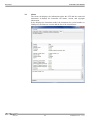
3.6
About
The About tab displays the information about the GUI and the connected
instrument. It displays the Controller GUI name, version, and copyright
information.
It also displays the instrument model, the instrument key (serial number or
COM port), the firmware version and the list of the selected axes.
21
EDH0341En1011 – 11/13
FC Series
EDH0341En1011 – 11/13
Controller GUI Manual
22
FC Series
Controller GUI Manual
Service Form
Your Local Representative
Tel.: __________________
Fax:___________________
Name: _________________________________________________
Return authorization #: ____________________________________
(Please obtain prior to return of item)
Company:_______________________________________________
Address: ________________________________________________
Date: __________________________________________________
Country: ________________________________________________
Phone Number: __________________________________________
P.O. Number: ____________________________________________
Fax Number: ____________________________________________
Item(s) Being Returned:____________________________________
Model#: ________________________________________________
Serial #: ________________________________________________
Description: ________________________________________________________________________________________________________
Reasons of return of goods (please list any specific problems): ________________________________________________________________
__________________________________________________________________________________________________________________
__________________________________________________________________________________________________________________
__________________________________________________________________________________________________________________
__________________________________________________________________________________________________________________
__________________________________________________________________________________________________________________
__________________________________________________________________________________________________________________
__________________________________________________________________________________________________________________
__________________________________________________________________________________________________________________
__________________________________________________________________________________________________________________
__________________________________________________________________________________________________________________
__________________________________________________________________________________________________________________
__________________________________________________________________________________________________________________
__________________________________________________________________________________________________________________
__________________________________________________________________________________________________________________
__________________________________________________________________________________________________________________
__________________________________________________________________________________________________________________
__________________________________________________________________________________________________________________
__________________________________________________________________________________________________________________
__________________________________________________________________________________________________________________
__________________________________________________________________________________________________________________
__________________________________________________________________________________________________________________
__________________________________________________________________________________________________________________
__________________________________________________________________________________________________________________
__________________________________________________________________________________________________________________
__________________________________________________________________________________________________________________
__________________________________________________________________________________________________________________
__________________________________________________________________________________________________________________
__________________________________________________________________________________________________________________
EDH0341En1011 – 11/13
23
Visit Newport Online at:
www.newport.com
North America & Asia
Newport Corporation
1791 Deere Ave.
Irvine, CA 92606, USA
Sales
Tel.: (800) 222-6440
e-mail: [email protected]
Technical Support
Tel.: (800) 222-6440
e-mail: [email protected]
Service, RMAs & Returns
Tel.: (800) 222-6440
e-mail: [email protected]
Europe
MICRO-CONTROLE Spectra-Physics S.A.S
9, rue du Bois Sauvage
91055 Évry CEDEX
France
Sales
Tel.: +33 (0)1.60.91.68.68
e-mail: [email protected]
Technical Support
e-mail: [email protected]
Service & Returns
Tel.: +33 (0)2.38.40.51.55