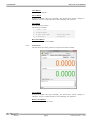
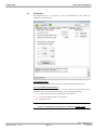
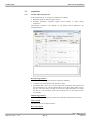
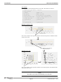
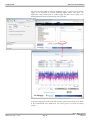
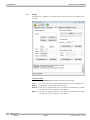
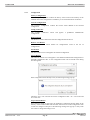
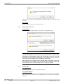
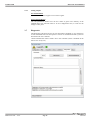
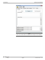
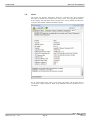
1
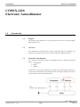
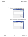
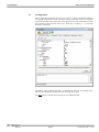
CONEX-LDS Electronic Autocollimator Controller GUI Manual V1.0.x For Motion, Think Newport™ CONEX-LDS EDH0331En1020 — 04/13 Electronic Autocollimator Page ii CONEX-LDS Electronic Autocollimator Table of Contents 1.0 Introduction .................................................................................................. 1 1.1 Purpose ....................................................................................................................................1 1.2 Overview .................................................................................................................................1 1.3 Controller state diagram...........................................................................................................1 2.0 Getting Started.............................................................................................. 3 2.1 Discover Instruments ...............................................................................................................3 3.0 User Interface................................................................................................ 4 3.1 General.....................................................................................................................................4 3.2 Configuration...........................................................................................................................5 3.3 Main.........................................................................................................................................8 3.3.1 Target tab...................................................................................................................8 3.3.2 Cluster view tab.........................................................................................................8 3.3.3 Positions tab ..............................................................................................................9 3.4 Calibration .............................................................................................................................10 3.5 Acquisition.............................................................................................................................12 3.6 3.5.1 CONEX-LDS Acquisition tab .................................................................................12 3.5.2 XPS Data Logger tab...............................................................................................14 Setup ......................................................................................................................................17 3.6.1 Configuration...........................................................................................................18 3.6.2 Dark current calibration...........................................................................................19 3.6.3 Low pass filter .........................................................................................................19 3.6.4 Analog outputs.........................................................................................................20 3.7 Diagnostics ............................................................................................................................20 3.8 About .....................................................................................................................................22 Service Form ........................................................................................................ 23 Page iii E DH0331En1020 — 04/13 CONEX-LDS EDH0331En1020 — 04/13 Electronic Autocollimator Page iv CONEX-LDS Electronic Autocollimator CONEX-LDS Electronic Autocollimator 1.0 Introduction 1.1 Purpose The purpose of this document is to provide instructions on how to use the CONEXLDS Controller GUI. 1.2 Overview The CONEX-LDS Controller GUIis a software application that has a Graphical User Interface (GUI) which allows the user to interact with the CONEX-LDS device. 1.3 Controller state diagram For a safe and consistent operation, the CONEX-LDS uses 3 different operational states: 1. Configuration 2. Ready 3. Measure In each state, only specific commands are accepted by the CONEX-LDS. Therefore, it is important to understand the state diagram below and which commands and actions cause transitions between the different states. E DH0331En1020 — 04/13 Page 1 CONEX-LDS Electronic Autocollimator When powering the CONEX-LDS, the controller starts initialization. When initialization is successful, the controller goes to the READY state. The controller can go to the CONFIGURATION state using the PW1 command. In the CONFIGURATION state, the CONEX-LDS allows changes to all configuration parameters, like gains or controller address. The PW0 command saves all changes to the controller’s memory and returns the controller back to the READY state. The device goes to the MEASURE state with the LB1 command. After sending the command, the status LED blinks for 3 seconds, indicating that the laser is going to be powered. At the end of this period the LED stops blinking and the laser starts emitting. This Controller GUI will display the current X and Y positions. Measurements can be recorded either through the command set or the two analog outputs. EDH0331En1020 — 04/13 Page 2 CONEX-LDS 2.0 Electronic Autocollimator Getting Started 2.1 Discover Instruments Start the Controller GUI from Newport\MotionControl\CONEX-LDS. Next, click on “Discover” button and number of instruments discovered will appear. This window allows the user to select a com port where the desired instrument is connected. Page 3 E DH0331En1020 — 04/13 CONEX-LDS Electronic Autocollimator When an XPS controller is connected, this window allows the user to choose XPS Option and enter IP settings. Next, click “Launch Applet” (Controller GUI) button. 3.0 User Interface 3.1 General This banner shows the laser status and the light level returned to the sensor as a percentage of the emitted power. The button “Laser ON” turns the laser on. When the laser LED is ON (green LED), the button turns to “Laser OFF” to turn it off. EDH0331En1020 — 04/13 Page 4 CONEX-LDS Electronic Autocollimator 3.2 Configuration The Configuration tab allows the user to view and / or change information related to the logging configuration and the instrument settings. Read only values are displayed for the log file name and log file path. The Logging Level can be selected from a drop down list that ranges from the Trace level, which logs everything (….) to the least detailed, Critical Error. The Polling Interval defines the delay, in milliseconds, between each polling event. The user may change the polling interval by entering a new value. The Save button saves the current settings to the configuration file. Page 5 E DH0331En1020 — 04/13 CONEX-LDS Electronic Autocollimator Configurable settings The following table describes all the settings that can be changed by the user. Parameter Description Values Default LoggingConfiguration Level PollingInterval NbDigits Logging level. Trace is the most detailed setting wherein the Controller GUI logs everything. Critical Error is the least detailed setting, which log errors that are defined to be critical. Trace Detail Equipment Message Info Warning Error Critical Errror InstrumentInformation The polling interval defines the delay, in milliseconds, between each polling An Integer event. Number of digits after the decimal An Integer point. Trace 200 6 Diagnostics Delay BufferDepth XMax XMin YMax YMin The time, in milliseconds, between An Integer commands sent to the instrument. Charts BufferDepth defines the maximum number of points displayed in the chart. XMax defined the maximum X limits of the position charts. XMax defined the minimum X limits of the position charts. XMax defined the maximum Y limits of the position charts. YMax defined the minimum Y limits of the position charts. Models \ InstrumentInfo InstrumentType Type of the main instrument NoOfInstruments Number of instruments that could be connected 1) CONEX-LDS (mandatory) 2) XPS (Optional) Instrument1 Type of the main instrument Instrument2 CommunicationChannelLDS CommunicationChannelXPS Type of the optional instrument The communication channel The communication channel 200 200 2000 -2000 2000 -2000 CONEXLDS 1 or 2 2 USB TCP CONEXLDS XPS USB TCP LDS XAxisName User name given for the X axis YAxisName User name given for the Y axis XDirection The axis direction for X axis. YDirection The axis direction for Y axis. XYOrientation XY Axes orientation Normal = XY Inverse = YX EDH0331En1020 — 04/13 Page 6 X Y Positive Negative Positive Negative Normal Inverse Positive Positive Normal CONEX-LDS Electronic Autocollimator LDSUnitConfiguration SelectedConfiguration ConfigurationArcSec Name of the selected configuration Predefined factory configuration of the connected CONEX-LDS. Predefined configuration ConfigurationMDeg Predefined configuration Configuration1 User configuration. Configuration2 User configuration. Configuration3 User configuration. Configuration4 User configuration. Configuration5 User configuration. Configuration6 User configuration. Configuration7 User configuration. Configuration8 User configuration. Configuration9 User configuration. Configuration10 User configuration. ConfigurationFactory String format: “name;unit;range;ratioX;ratioY” String format: “name;unit;range;ratioX;ratioY” String format: “name;unit;range;ratioX;ratioY String format: “name;unit;range;ratioX;ratioY String format: “name;unit;range;ratioX;ratioY String format: “name;unit;range;ratioX;ratioY String format: “name;unit;range;ratioX;ratioY String format: “name;unit;range;ratioX;ratioY String format: “name;unit;range;ratioX;ratioY String format: “name;unit;range;ratioX;ratioY XPS \ XPSDataLogger ExternalTrigger XAnalogInput YAnalogInput GPIO1.DI GPIO2.DI GPIO3.DI GPIO4.DI GPIO2.ADC1 XPS Analog input used in the XPS GPIO2.ADC2 gathering to get X-axis positions from GPIO2.ADC3 the CONEX-LDS. GPIO2.ADC4 GPIO2.ADC1 XPS Analog input used in the XPS GPIO2.ADC2 gathering to get Y-axis positions from GPIO2.ADC3 the CONEX-LDS. GPIO2.ADC4 LDSPerformanceVerification \ PerformanceVerificationKit XPS Digital input used as an external trigger to start an XPS gathering (use TTL input 1 only). ReferenceAngleValue Serial number of the performance verification kit. CONEX-LDS-VER optical wedge Reference Angle value. LDSPInformation LDSSerialNumber The “CD” command will return the serial number of the CONEX-LDS KitSerialNumber Page 7 GPIO1.DI GPIO2.ADC 1 GPIO2.ADC 2 E DH0331En1020 — 04/13 CONEX-LDS Electronic Autocollimator 3.3 Main The Main tab displays the main controls in the Controller GUI similar to the virtual front panel in Lab view. It is updated at every polling event. 3.3.1 Target tab This tab shows the current position in (X, Y), refreshed at every PollingInterval cycle. The current position is represented by a point. Four automatic zoom levels are available to change the scale of the display. 3.3.2 Cluster view tab The cluster view tracks and plots the current position (X, Y) continuously. EDH0331En1020 — 04/13 Page 8 CONEX-LDS Electronic Autocollimator Clear Button Clears the plotted points. Freeze Button Freezes the display and stops refreshing. The button label “Freeze’ changes to “Resume”, once it is clicked. In order to start refreshing, click “Resume”. Save Button Saves the data in a text file. The format is as follows: 1. Comment line 2. Polling delay 3. X User axis name X User axis name 4. X position Y position Reset zoom Button Resets the zoom scale to the default. 3.3.3 Positions tab This tab shows the current positions in a large font for better visibility. Freeze Button Freezes the display and stops refreshing. The button label “Freeze’ changes to “Resume”, once it is clicked. In order to start refreshing, click “Resume”. Relative Zero Button Resets the current position to zero. Page 9 E DH0331En1020 — 04/13 CONEX-LDS Electronic Autocollimator 3.4 Calibration The Calibration tab is to be used to verify the CONEX-LDS is still within the calibration set at the factory. Last calibration date Last calibration date performed at the factory for the CONEX-LDS instrument. Next recommended calibration date The Last and Next calibration dates are set in the LDS instrument during factory calibration. The next calibration date display color indicates the following: Green: there is plenty of time to schedule the next calibration. Orange: the next calibration date is getting close. Red: calibration is due. NOTE Newport recommends performing factory calibration EACH YEAR. EDH0331En1020 — 04/13 Page 10 CONEX-LDS Electronic Autocollimator Start performance verification Button Opens a user-friendly interface to validate the CONEX-LDS calibration. The label on the button changes to “Stop” to cancel the current recalibration. Error ≤ 3% = GREEN indicator, OK Error > 3% = RED indicator, consider sending the CONEX-LDS to the factory for calibration REFERENCE INFORMATION The optical wedge of the CONEX-LDS-VER calibration verification kit induces an angular deviation to the autocollimator's beam. This deviation corresponds to a measurement angle of approximately 1000 µrad. The exact angle is measured and delivered with each CONEX-LDS-VER Kit. The verification process consists of 4 measurements, spaced 90° apart on the PSD. These measurements are compared to the CONEX-LDS-VER reference angle set in the Configuration tab. Before performing this verification and inserting the optical wedge, the mirror must be centered so the CONEX-LDS reads X = 0 and Y = 0 ±10 µrad. Page 11 E DH0331En1020 — 04/13 CONEX-LDS Electronic Autocollimator 3.5 Acquisition 3.5.1 CONEX-LDS Acquisition tab In the Acquisition tab, two acquisition methods are available: 1. Manual acquisition: “Manual trigger” button 2. Dynamic acquisition: “Dynamic trigger” button (changes to “Stop” during acquisition) The dynamic acquisition rate depends on the polling interval defined in the Configuration tab. Dynamic trigger Button This button starts running a succession of acquisition defined by: A number of points defined by the “Nb points” field The default delay value is set to 100 ms. This value is limited by the computer and the communication rate. The save button allows saving the X and Y data as well as the time. This time stamp will help get an idea of system performance by setting the delay to 1 ms (minimum value). The maximum rate is in the range of some tens of Hertz. Manual trigger Button This button triggers the acquisition of the current CONEX-LDS position (one shot). Clear” button This button clears all acquired positions. Reset zoom Button Resets the zoom scale. EDH0331En1020 — 04/13 Page 12 CONEX-LDS Electronic Autocollimator Save Button This button saves the acquired positions in a text file. The format is as follows: 1. Acquisition type (manual or dynamic) 2. Date and time 3. Comment: Comment line 4. Nb points: Number of points 5. Period (ms): Polling delay in milliseconds 6. Low pass filter (ms): low pass filter frequency in ms 7. X user axis name Y user axis name 8. X position #1 Y position #1 9. … … 10. X position #N Y position #N Zoom in “X and Y” view Sets a new window of axis position based on start and end points as defined with the mouse cursor click. Button to reset the last scale view zoom Zoom in “XY” view Sets a new window of axis positions based on start and end points (XY) defined with the mouse cursor click. NOTE The “Reset zoom” button automatically resets all zooms. Page 13 E DH0331En1020 — 04/13 CONEX-LDS Electronic Autocollimator 3.5.2 XPS Data Logger tab This function is available only if an XPS Universal Motion Controller is physically connected and configured in the Configuration tab. The “Run” button starts the acquisition with the XPS. Once clicked, the “Run” button changes to “Stop”. The “Stop” button aborts the current XPS acquisition. The results are saved in an XPS data file. NOTE For additional information on the XPS and to download the manual, visit newport.com. Three available triggers: 1. Immediate 2. Start on TRIG 3. Synchronized on TRIG In all 3 cases below, the analog outputs of the CONEX-LDS must be connected to GPIO2 of the XPS at AI1 and AI2. The default pins can be changed in the configuration tab to AI1 thru AI4 (pins 14 to 17). EDH0331En1020 — 04/13 Page 14 CONEX-LDS Electronic Autocollimator Start on trig mode always refers to the TTL input 1 of GPIO1 to GPIO4 connectors. GPIO1 is the default, which can be changed in the configuration tab. GPIO1 TTL input1 = pin4 GPIO2 TTL input1 = pin3 GPIO3 TTL input1 = pin9 GPIO4 TTL input1 = pin1 1) Immediate TRIGGER (Standard XPS gathering) Number of points Frequency 2) Start on external TRIGGER (Standard XPS gathering) Number of points Frequency 3) Synchronized on external TRIGGER (TRIG IN : External gathering) Number of points The Synchronized on Trig mode refers to the "Syncro input" pin6 of TRIG IN connector in the XPS. Page 15 E DH0331En1020 — 04/13 CONEX-LDS Electronic Autocollimator The result of the acquisition using an immediate trigger or starting on an external trigger can be displayed in the XPS gathering display feature. See below. For acquisitions using synchronized on external trigger, the data will be stored in the GatheringExternal.dat file found in the ftp site of the XPS. To properly display the results in the XPS interface, gains must be properly set. Refer to the CONEX-LDS Users Manual for the correct gains to use with the analog outputs. EDH0331En1020 — 04/13 Page 16 CONEX-LDS Electronic Autocollimator 3.6 Setup The Setup tab configures the CONEX-LDS parameters used in the graphical user interface. Unit information A CONEX-LDS configuration is based on the following parameters: Unit: It’s a string that represents the units defined by the user for the application. Range: It’s the display range applied in the application. Ratio X: It’s the ratio X applied to the factory’s coefficient X and the factory’s offset X to define the current coefficient X and offset X. Ratio Y: It’s the ratio Y applied to the factory’s coefficient Y and the factory’s offset Y to define the current coefficient Y and offset Y. Page 17 E DH0331En1020 — 04/13 CONEX-LDS Electronic Autocollimator 3.6.1 Configuration Factory Configuration The “Factory” configuration contains the factory values saved in the memory of the CONEX-LDS. This configuration is mandatory to use with Calibration verification. Current Configuration The “Current” configuration contains the current values defined in the selected configuration. Config Combo-box The “Config” combo-box selects and applies a predefined CONEX-LDS configuration. Remove Button The “Remove” button deletes the selected configuration from the list. Remove ALL Button The “Remove ALL” button deletes all configurations saved in the list of configurations. Save Button The “Save” button saves and applies the selected configuration. Save as Button The “Save as” button saves and applies a user-defined CONEX-LDS configuration in the XML configuration file. A new configuration name can be entered in the dialog box that appears: If the configuration name already exists, the following message pops up. Choosing “Yes” will overwrite the current configuration and “ No “ will create and save a new one. Set permanent Button Saves the new values for the range, the calibration coefficients and the offsets in the memory of the CONEX-LDS. The controller will need to be in the Configuartion state in order for changes to take place. The following message will pop up to verify if the user wants to change the settings or not: EDH0331En1020 — 04/13 Page 18 CONEX-LDS Electronic Autocollimator Choosing “Yes” will save the parameters in memory and “No” will cancel the operation. Set Volatile Writes to volatile memory and is lost upon reboot. 3.6.2 Dark current calibration Update Button Updates the offsets. Follow the pop up messages to complete the process. NOTE This function minimizes the effects of internal reflections that reach the sensor and impact the measurement signal. The laser should be ON for a least 10 minutes before performing this calibration. A non-reflective shutter should be inserted as close as possible to the autocollimator beam output. This calibration is performed on each CONEX-LDS at the factory and can be performed on site. Be familiar with the process before attempting to proceed, since it could be source of measurement errors, if not properly done. 3.6.3 Low pass filter Set volatile Button Applies the new value of the low pass filter frequency. Set permanent Button Saves the new value of the low pass filter frequency in the memory of the CONEXLDS. The controller will need to b in Configuration state, in order for the changes to take place. Page 19 E DH0331En1020 — 04/13 CONEX-LDS Electronic Autocollimator 3.6.4 Analog outputs Set volatile Button The “Set volatile” button applies a new values of gains. Set permanent Button The “Set permanent” button saves the new values of gains in the memory of the CONEX-LDS. The controller must be in the Configuration state, in order for the changes to take place. 3.7 Diagnostics The Diagnostics tab allows the user to enter instrument commands, to view the history of sent commands and received responses. The list of commands and their syntax are described in the user’s manual. “Send Command file” button sends a file to the controller (all the commands in the file are sent one by one). EDH0331En1020 — 04/13 Page 20 CONEX-LDS Electronic Autocollimator NOTE Refer to the CONEX-LDS Users manual for the description of the commands. Page 21 E DH0331En1020 — 04/13 CONEX-LDS Electronic Autocollimator 3.8 About The About tab displays information about the Controller GUI and connected instrument. It displays the Controller GUI name, version, and copyright information. It also displays the instrument model, instrument key (serial number) and firmware versions of the CONEX-LDS and the XPS controller. For an external data logger, refere to the analog out pinouts and the gains table to convert from voltage to position. Refer to the CONEX-LDS Users manual for more information. EDH0331En1020 — 04/13 Page 22 CONEX-LDS Electronic Autocollimator Service Form Your Local Representative Tel.: ___________________ Fax: ___________________ Name: __________________________________________________ Company: _______________________________________________ Return authorization #: _____________________________________ (Please obtain prior to return of item) Address:_________________________________________________ Date: ___________________________________________________ Country:_________________________________________________ Phone Number: ___________________________________________ P.O. Number: ____________________________________________ Fax Number: _____________________________________________ Item(s) Being Returned: ____________________________________ Model#: _________________________________________________ Serial #: _________________________________________________ Description: __________________________________________________________________________________________________________ Reasons of return of goods (please list any specific problems):__________________________________________________________________ ____________________________________________________________________________________________________________________ ____________________________________________________________________________________________________________________ ____________________________________________________________________________________________________________________ ____________________________________________________________________________________________________________________ ____________________________________________________________________________________________________________________ ____________________________________________________________________________________________________________________ ____________________________________________________________________________________________________________________ ____________________________________________________________________________________________________________________ ____________________________________________________________________________________________________________________ ____________________________________________________________________________________________________________________ ____________________________________________________________________________________________________________________ ____________________________________________________________________________________________________________________ ____________________________________________________________________________________________________________________ ____________________________________________________________________________________________________________________ ____________________________________________________________________________________________________________________ ____________________________________________________________________________________________________________________ ____________________________________________________________________________________________________________________ ____________________________________________________________________________________________________________________ ____________________________________________________________________________________________________________________ ____________________________________________________________________________________________________________________ ____________________________________________________________________________________________________________________ ____________________________________________________________________________________________________________________ ____________________________________________________________________________________________________________________ ____________________________________________________________________________________________________________________ ____________________________________________________________________________________________________________________ ____________________________________________________________________________________________________________________ ____________________________________________________________________________________________________________________ ____________________________________________________________________________________________________________________ Page 23 E DH0331En1020 — 04/13 Visit Newport Online at: www.newport.com North America & Asia Newport Corporation 1791 Deere Ave. Irvine, CA 92606, USA Sales Tel.: (800) 222-6440 e-mail: [email protected] Technical Support Tel.: (800) 222-6440 e-mail: [email protected] Service, RMAs & Returns Tel.: (800) 222-6440 e-mail: [email protected] Europe MICRO-CONTROLE Spectra-Physics S.A.S 9, rue du Bois Sauvage 91055 Évry CEDEX France Sales Tel.: +33 (0)1.60.91.68.68 e-mail: [email protected] Technical Support e-mail: [email protected] Service & Returns Tel.: +33 (0)2.38.40.51.55