1
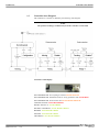
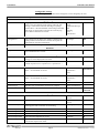
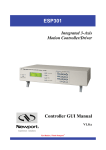
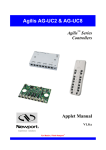
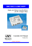
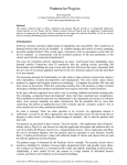
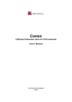
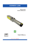
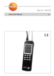
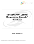
CONEX-CC
Single-Axis DC Motion
with Controller/Driver
Controller GUI Manual
V2.0.x
For Motion, Think Newport™
CONEX-CC
EDH0277En1031 — 11/13
Controller GUI Manual
Page ii
CONEX-CC
Controller GUI Manual
Table of Contents
1.0
Introduction .................................................................................................. 1
1.1
Purpose .................................................................................................................................... 1
1.2
Overview ................................................................................................................................. 1
1.3
Controller State Diagram ......................................................................................................... 2
2.0
Getting Started .............................................................................................. 3
2.1
Discover Instruments ............................................................................................................... 3
3.0
User Interface ................................................................................................ 4
3.1
Configuration ........................................................................................................................... 4
3.2
Main ......................................................................................................................................... 7
3.3
Tracking ................................................................................................................................... 9
3.4
Diagnostics ............................................................................................................................ 11
3.5
About ..................................................................................................................................... 12
Service Form ........................................................................................................ 13
Page iii
EDH0277En1031 — 11/13
CONEX-CC
EDH0277En1031 — 11/13
Controller GUI Manual
Page iv
CONEX-CC
Controller GUI Manual
CONEX-CC
Single-Axis DC Motor Controller/Driver
1.0
Introduction
1.1
Purpose
The purpose of this document is to provide instructions on how to use the CONEXCC Controller GUI.
1.2
Overview
The CONEX-CC Controller GUI is a graphical user interface (GUI) which allows the
user to interact with the CONEX-CC controller that is connected to stages with DC
motors and encoder feedback. The user can initiate moves, change the state of the
controller, adjust parameters, etc.
EDH0277En1031 — 11/13
Page 1
CONEX-CC
Controller GUI Manual
1.3
Controller State Diagram
The CONEX-CC controller is defined by the following state diagram.
NOTE
The position tracking is available only from the controller version 2.0.0
Controller’s LED display:
NOT REFERENCED: If everything is OK then SOLID ORANGE.
NOT REFERENCED: If hardware faults or wrong parameters then SOLID RED.
NOT REFERENCED: If end of runs then SLOW BLINK ORANGE.
CONFIGURATION: SLOW BLINK RED.
READY / READY T: SOLID GREEN.
DISABLE / DISABLE T: SLOW BLINK GREEN.
HOMING: FAST BLINK GREEN.
MOVING: FAST BLINK GREEN.
TRACKING: FAST BLINK GREEN.
EDH0277En1031 — 11/13
Page 2
CONEX-CC
2.0
Controller GUI Manual
Getting Started
2.1
Discover Instruments
Start the Controller GUI from Newport\MotionControl\CONEX-CC.
Next, click on “Discover” button and the number of instruments discovered will
appear. This window allows the user to select a com port where the desired instrument
is connected.
NOTE
When more than one CONEX-CC instrument is connected, this window allows
the user to switch the instruments between X and Y axes. To discern a com port
for a specific instrument, note their COM number in the Device Manager when
the connection is added.
Next, click “Launch Applet” button.
Page 3
EDH0277En1031 — 11/13
CONEX-CC
3.0
Controller GUI Manual
User Interface
3.1
Configuration
The Configuration tab allows the user to view and / or change information related to
the logging configuration and the instrument settings. Read only values are displayed
for the log file name and the log file path. The logging level may be changed to any of
the settings in the drop-down list on the right hand side. Trace is the most detailed of
the settings and when this setting is selected the Controller GUI logs everything.
Critical Error is the least detailed of the settings and when this setting is selected the
Controller GUI will only log errors that are defined to be critical.
The polling interval defines the number of milliseconds between each time the
Controller GUI polls the CONEX-CC for the latest information. The user may change
the polling interval by entering a value. Diagnostics Delay defines the time delay in
milliseconds between each command sent from a text file.
InstrumentType and NoOfInstruments display the name and number of connected
instruments.
The Save button allows to save the current settings to the configuration file.
EDH0277En1031 — 11/13
Page 4
CONEX-CC
Controller GUI Manual
Configurable settings
The following table describes all the settings that can be changed by the user.
Parameter
Description
Values
Default
Trace
Detail
Equipment Message
Info
Warning
Error
Critical Error
Trace
LoggingConfiguration
Level
Logging level.
Trace is the most detailed of the settings and when this
setting is selected the Controller GUI logs everything.
Critical Error is the least detailed of the settings and when
this setting is selected the Controller GUI will only log
errors that are defined to be critical.
InstrumentInformation
PollingInterval
The polling interval defines the number of milliseconds
(delay) between each time the Controller GUI polls the
instrument for the latest information.
An Integer
200
NbDigits
Number of fractional digits after the decimal point.
An Integer
6
The delay defines the number of milliseconds between each An Integer
sent command from a text file.
5
Diagnostic
Delay
MemorizePositionsRollingBuffer
Buffer Depth
BufferDepth defines the maximum number of
analog I/O values displayed in the chart.
Positions
Positions is a list of memorized positions. The format is
“Name of positions #1; X position #1; Y position #2…”
Models\InstrumentInfo
XAxis
XAxis defines the instrument for X axis.
None = no instrument for X axis
Instrument 1
Instrument 2
None
Instrument 1
YAxis
YAxis defines the instrument for Y axis.
None = no instrument for Y axis
Instrument 1
Instrument 2
None
Instrument 2
CommunicationChannel
The communication channel
USB
USB
InstrumentType
Specifies type of instrument connected to computer
Name of instrument
NoOfInstruments
Specifies number of instruments connected to computer
An Integer
0 if nothing is
connected
TrackingConfiguration
XDirection
The axis direction for X axis.
Normal
Inverse
Normal
YDirection
The axis direction for Y axis.
Normal
Inverse
Normal
StartedSensibility
The started sensibility defines the zoom level of the
tracking panel after Controller GUI launching.
An Integer (1<20)
4
MinimumAmplitudeX
The minimum amplitude for X axis.
A Double
0.001
MaximumAmplitudeX
The maximum amplitude for X axis.
A Double
20
MinimumAmplitudeY
The minimum amplitude for Y axis.
A Double
0.001
MaximumAmplitudeY
The maximum amplitude for Y axis.
A Double
20
IncrementalStep
The maximum incremental step when the tracking is in
incremental displacement mode.
A Double
0.05
Page 5
EDH0277En1031 — 11/13
CONEX-CC
Controller GUI Manual
This table describes mouse parameters for the MouseConfiguration section.
MouseConfiguration
EnterPositionTracking
Activate the tracking mode.
MouseButton/MouseEvent*
Middle/Click
ExitPositionTracking
Desactivate the tracking mode.
MouseButton/MouseEvent*
Middle/Click
SelectXaxis
Select/Unselect X axis.
MouseButton/MouseEvent*
Left/Click
SelectYaxis
Select/Unselect Y axis.
MouseButton/MouseEvent*
Right/Click
IncreaseSensibility
Increase the zoom level of the tracking
panel.
MouseButton/MouseEvent*
Middle/Wheel up
DecreaseSensibility
Decrease the zoom level of the tracking
panel.
MouseButton/MouseEvent*
Middle/Wheel
down
MemorizeCurrentPosition
Save the current positions.
MouseButton/MouseEvent*
Left/Double-Click
EDH0277En1031 — 11/13
Page 6
CONEX-CC
Controller GUI Manual
3.2
Main
The Main tab displays the main controls in the Controller GUI like a virtual front
panel. It is updated each time the polling interval timer expires.
One Main tab by axis:
1. Main X
2. Main Y
“Initialization and Configuration”
In the “Initialization and Configuration” area, the first button changes the
controller status to “Enabled” or “Disabled”. To see the different controller
states, refer to the controller state diagram in section 1.3. The second button
“Save Pos.” memorizes the current positions (X and Y) in the combo box. As
soon as a new position is memorized, this is displayed in the trace.
“Current Position”
In the “Current Position” area, the current position X (or Y) is displayed in a
text box and visualized in a slider. The slider limits are defined with the ends
of run. An LED icon shows the current controller state. When the mouse
hovers over the LED icon, the controller state is displayed in an information
balloon.
Page 7
EDH0277En1031 — 11/13
CONEX-CC
Controller GUI Manual
“Incremental Motion / PR-Move Relative”
In the “Incremental Motion / PR-Move Relative” area, two increment values can be
defined. For each defined increment, a relative move is performed in either the
negative direction or positive direction.
“Cyclic Motion” and “Target position / PA-Move Absolute”
In the “Cyclic Motion” area, a motion cycle is configured with a number of cycles
(Cycle) and a dwell time in milliseconds. The motion cycle gets the defined target
positions from the “Target position / PA-Move Absolute’ area to perform the cycle.
Target #1
Tempo (Dwell)
Target #2
Loop #1
Tempo (Dwell)
Tempo (Dwell)
Loop #2
Tempo (Dwell)
Loop #N
In the “Target position / PA-Move Absolute” area, two target positions can be
defined. The “Go to” button allows executing the absolute move to go to the specified
target position.
“Motion Configuration Values”
In the “Motion Configuration Values”, the current ends of run and the velocity are
displayed in a disabled text box: “Minimum end of run”, “Maximum end of run” and
“Velocity”. These ends of run and the velocity can be modified and saved with the
“Set” button.
Memorised positions
The combo box allows memorizing the positions get by the “Save Pos.” button. Each
of these positions can be renamed or deleted. To execute an absolute move to go to
one of these memorized positions, select one item of the combo box and click on “Go
to” button. When the mouse moves over to the combo box, the positions of the
selected memorized position are shown in an information balloon.
Rename a memorized position: Select an item from the combo box, edit the position
name to change it and click on the “Rename” button to save the new position name.
Delete a memorized position: Select an item from the combo box, right-click on the
mouse and select the “Delete” menu to delete the selected memorized position.
EDH0277En1031 — 11/13
Page 8
CONEX-CC
Controller GUI Manual
3.3
Tracking
The Tracking tab accesses the position tracking mode. The tracking position mode
uses the mouse.
NOTE
In the tracking mode, the cursor is confined to the tracking position area.
The “Enable/Disable” button executes the next enable command to change the
controller status. Its name changes in relation to the controller state. To see the
different controller states, refer to the controller state diagram in section 1.3.
An LED icon shows the current controller state. When the mouse hovers over
the LED icon, the controller state is displayed inside an information balloon.
Two text boxes display the current positions (X and Y)
The combo box allows memorizing the positions with a mouse double-click.
Each of these positions can be renamed or deleted. To execute an absolute
move to go to one of these memorized positions, select one item from the
combo box and click on “Go to” button. When the mouse moves over to the
combo box, the positions of the selected memorized position are showed in an
information balloon.
Rename a memorized position: Select an item from the combo box, edit the
position name to change it and click on the “Rename” button to save the new
position name.
Page 9
EDH0277En1031 — 11/13
CONEX-CC
Controller GUI Manual
Delete a memorized position: Select an item from the combo box, right-click
on the mouse and select the “Delete” menu to delete the selected memorized
position.
Tracking panel and mouse
The current position is represented by a black spot.
The amplitudes (X and Y) are defined with the ends of run.
First click (middle mouse button) enters the tracking mode and the mouse
cursor position is attached to the current position. As soon as the tracking
mode is activated, the cursor is represented by a hand
and the CONEXCC goes to the TRACKING state. Next, each mouse move generates a
displacement command. The second click (middle mouse button) exits the
tracking mode.
The wheel button increases or decreases the sensitivity..
A right double-click memorizes the current positions (X and Y) in the combo
box. Each new memorized position is displayed in the trace.
Default mouse configuration:
One click: Enter / Exit the tracking position mode.
Roll up:
increase zoom factor
Roll down: decrease zoom factor
One click:
One click:
Select X axis only /
Reselect XY axes
Select Y axis only /
Reselect XY axes
Double click:
Memorise the current
position
NOTE
The mouse configuration can be modified in the “Configuration” tab.
EDH0277En1031 — 11/13
Page 10
CONEX-CC
Controller GUI Manual
3.4
Diagnostics
The Diagnostics tab allows the user to enter instrument commands and to view the
history of commands that were sent and the responses that were received. This list of
commands and the syntax of each command can be found in the user’s manual.
A file of commands can be sent line by line to the controller with the
“Send Command file” button.
Page 11
EDH0277En1031 — 11/13
CONEX-CC
Controller GUI Manual
3.5
About
The About tab displays the information about the Controller GUI and the connected
instrument. It displays the Controller GUI name, version, and copyright information.
It also displays the instrument model, instrument key (serial number) and firmware
version for X and Y axes.
EDH0277En1031 — 11/13
Page 12
CONEX-CC
Controller GUI Manual
Service Form
Your Local Representative
Tel.: __________________
Fax:___________________
Name: _________________________________________________
Company:_______________________________________________
Return authorization #: ____________________________________
(Please obtain prior to return of item)
Address: ________________________________________________
Date: __________________________________________________
Country: ________________________________________________
Phone Number: __________________________________________
P.O. Number: ____________________________________________
Fax Number: ____________________________________________
Item(s) Being Returned:____________________________________
Model#: ________________________________________________
Serial #: ________________________________________________
Description: ________________________________________________________________________________________________________
Reasons of return of goods (please list any specific problems): ________________________________________________________________
__________________________________________________________________________________________________________________
__________________________________________________________________________________________________________________
__________________________________________________________________________________________________________________
__________________________________________________________________________________________________________________
__________________________________________________________________________________________________________________
__________________________________________________________________________________________________________________
__________________________________________________________________________________________________________________
__________________________________________________________________________________________________________________
__________________________________________________________________________________________________________________
__________________________________________________________________________________________________________________
__________________________________________________________________________________________________________________
__________________________________________________________________________________________________________________
__________________________________________________________________________________________________________________
__________________________________________________________________________________________________________________
__________________________________________________________________________________________________________________
__________________________________________________________________________________________________________________
__________________________________________________________________________________________________________________
__________________________________________________________________________________________________________________
__________________________________________________________________________________________________________________
__________________________________________________________________________________________________________________
__________________________________________________________________________________________________________________
__________________________________________________________________________________________________________________
__________________________________________________________________________________________________________________
__________________________________________________________________________________________________________________
__________________________________________________________________________________________________________________
__________________________________________________________________________________________________________________
__________________________________________________________________________________________________________________
__________________________________________________________________________________________________________________
Page 13
EDH0277En1031 — 11/13
Visit Newport Online at:
www.newport.com
North America & Asia
Newport Corporation
1791 Deere Ave.
Irvine, CA 92606, USA
Sales
Tel.: (800) 222-6440
e-mail: [email protected]
Technical Support
Tel.: (800) 222-6440
e-mail: [email protected]
Service, RMAs & Returns
Tel.: (800) 222-6440
e-mail: [email protected]
Europe
MICRO-CONTROLE Spectra-Physics S.A.S
9, rue du Bois Sauvage
91055 Évry CEDEX
France
Sales
Tel.: +33 (0)1.60.91.68.68
e-mail: [email protected]
Technical Support
e-mail: [email protected]
Service & Returns
Tel.: +33 (0)2.38.40.51.55