1
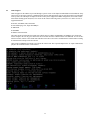
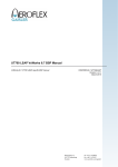
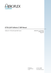
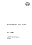
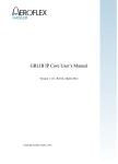
Standard Products UT700-LEAP-MEZ LEAP Leon Expandable Application Platform LEAP Board Stack User Guide August 5, 2015 www.aeroflex.com/LEON 1.0 Introduction............................................................................................................................ 4 1.1 Scope............................................................................................................................ 4 1.2 Aeroflex LEAP Overview ........................................................................................... 4 1.3 LEAP Board Stack Package Contents (Main SBC Only)............................................ 5 1.4 LEAP Board Stack Package Contents (Main SBC Mezzanine) .................................. 5 1.5 Aeroflex LEAP Board Power Input............................................................................. 5 1.6 Reference documents................................................................................................... 6 2.0 Architecture............................................................................................................................ 7 2.1 UT700 Brief Overview ................................................................................................ 7 2.2 UT700 LEON 3 SPARC V8 Processor........................................................................ 8 2.3 Memory interfaces ....................................................................................................... 8 2.4 SpaceWire links ........................................................................................................... 9 2.5 UT700 Timer Unit ..................................................................................................... 10 2.6 System Reset Button.................................................................................................. 10 2.7 System Status LED Indicators ................................................................................... 10 2.8 USB General Purpose UART I/F............................................................................... 10 2.9 UT700 Ethernet I/F.................................................................................................... 11 2.10 System Clock Selection ............................................................................................. 12 2.11 UT700 General Purpose I/O ...................................................................................... 12 2.12 UT700 1553B Port to Mezzanine .............................................................................. 13 2.13 UT700 CAN Bus Interface ........................................................................................ 13 2.14 UT700 SPI Bus Interface........................................................................................... 14 2.15 LEAP Cores ............................................................................................................... 14 2.16 AHB Core Mapping................................................................................................... 15 2.17 Non-Volatile Memory Mapping................................................................................. 16 2.18 SDRAM Memory Mapping ....................................................................................... 16 3.0 Mezzanine Power Interface................................................................................................. 17 3.1 Mezzanine Connector Power ..................................................................................... 17 4.0 Optional LEAP with Mezzanine Card (Base PN: 4250252-000) ..................................... 18 4.1 Mezzanine Card SPI Interface ................................................................................... 18 4.2 Mezzanine Card CAN Bus 1 Interface ...................................................................... 19 4.3 Mezzanine Card CAN 2 Bus Interface ...................................................................... 20 4.4 Mezzanine Card 1553B Interface .............................................................................. 21 4.5 Mezzanine Card SpaceWire Interface ....................................................................... 22 5.0 Software development ......................................................................................................... 23 5.1 Tool chains ................................................................................................................. 23 5.2 Downloading software to the target system............................................................... 23 5.3 RTEMS demo ............................................................................................................ 23 5.4 VxWorks .................................................................................................................... 23 5.5 Linux Support ............................................................................................................ 24 2 1.0 Introduction 1.1 Scope This document describes the Leon Expandable Application Platform (LEAP) design implemented for the Aeroflex UT700 LEON3-FT processor. The LEAP card design is intended to be a low-cost development platform to familiarize users with the Aeroflex UT700 processor, as well as allow custom expansion based on application requirements. The following hardware and software components are required in order to use the LEAP evaluation board: • PC work station running Windows XP PRO, Windows 7 or Linux • Aeroflex Gaisler GRMON-Pro For new users to UT700 software development, the following tools are recommended: 1.2 • BCC Bare-C LEON Cross-compiler • RCC RTEMS ERC32/LEON Cross-compiler system Aeroflex LEAP Overview The Aeroflex LEAP provides a flexible development platform for customers wanting to develop software that works on the Aeroflex UT700 Standard Product with minimal cost investment. The Aeroflex LEAP has the following features: • An Aeroflex UT700 LEON 3 FT standard product • 8 Mbytes NV memory storage • 32Mbytes SDRAM • One USB UART interface via standard USB • One 10T/100 Mbit/s Ethernet port • JTAG interface for programming and debug of UT700 LEON 3FT (requires XILINX USB Platform Cable) • One 192-pin mezzanine card expansion connector • On-board Programmable LEAP main clock A block diagram of the LEAP card is shown in Figure 1. 3 Figure 1: LEAP Top-Level Block Diagram and Assembly (AX9-4250252) 4 1.3 1.4 1.5 UT700-LEAP Board Stack Package Contents (Main SBC Only) • One LEAP card (main SBC & Memory) • One A/C Wall Adapter • One Euro-style A/C interface plate • One US-style A/C interface plate • One LEAP Board User Guide (CD) UT700-LEAP-MEZ Board Stack Package Contents (Main SBC and Mezzanine) • One LEAP card (main SBC & Memory) • One LEAP card (mezzanine with SPI display, two CAN bus, two SpaceWire and a dual-redundant CHA/CHB 1553B ports) • One A/C Wall Adapter • One Euro-style A/C interface plate • One US-style A/C interface plate • One LEAP Board User Guide (CD) Aeroflex LEAP Board Power Input The Aeroflex LEAP utilizes one AC wall-adapter to provide the 3.3VDC used to operate the board. Aeroflex includes the A/C wall adapter in the delivery package to enable “out-of-the-box” software operation and development. Connect the A/C wall adapter DC port-side cable to the LEAP card as shown in Figure , the wall-adapter side should be connected to a compatible A/C wall outlet. A/C Wall Adapter (included) DC Power Side Input Jack/Port Figure 2: LEAP Power Input 1.6 Reference documents • N/A 5 2.0 Architecture 2.1 UT700 Brief Overview The Aeroflex LEAP design consists of the UT700 Leon 3FTprocessor and a set of IP cores connected through the AMBA AHB/APB buses. USB XILINX JTAG RJ45 Mezzanine Mezzanine Serial Dbg Link JTAG Dbg Link Ethernet MAC SpaceWire Links Multi-core CAN-2.0 LEON 3 SOC DSU3 LEON3 Processor AMBA AHB AHB Controller Memory Controller AMBA APB AHB/APB Bridge 1553B SPI UART Timers IrqCtrl I/O port 32-bit memory bus NVMEM Mezzanine SDRAM USB WDOG (LED) Mezzanine Figure 3: UT700 LEAP Block Diagram The design is centered around the AMBA Advanced High-Speed bus (AHB), to which the LEON 3 processor and other high-bandwidth devices are connected. External memory is accessed through a combined PROM/SDRAM memory controller. The on-chip peripheral devices include four SpaceWire links, one Ethernet 10/100 Mbit MAC, dual CAN-2.0 interface, one SPI interface, a dual channel 1553B interface, serial and JTAG debug interfaces, a UART, interrupt controller, timers and a 16-bit general purpose I/O port. 6 2.2 UT700 LEON 3 SPARC V8 Processor The LEAP’s UT700 design is based the LEON 3 SPARC V8 processor. The processor core is configured with a cache system consisting of 4Kbyte, 4-way set associative Instruction and 4Kbyte, 4-way Data cache. The LEON3 debug support unit (DSU3) is a user port for downloading and debugging of programs through the serial or JTAG ports. 3-Port Register File Trace Buffer IEEE-754 FPU Co-Processor 7-Stage Integer pipeline HW MUL/DIV Local IRAM I-Cache Debug port Debug support unit Interrupt port Interrupt controller Local DRAM D-Cache I/D MMU AHB I/F AMBA AHB Master (32-bit) Figure 4: LEON 3 processor core block diagram 2.3 Memory interfaces The external memory is interfaced through a combined PROM/SDRAM memory controller core (UT700). The Aeroflex LEAP card provides 8 MB of Non-Volatile memory, and 32 MB of SDRAM for system program/data memory. APB A AHB ROMSN[1:0] OEN WRITEN CS OE WE IOSN CS OE WE MEMORY PROM A I/O (NU) A SRAM (NU) A D D CONTROLLER RAMSN[4:0] RAMOEN[4:0] RWEN[3:0] MBEN[3:0] SDCLK SDCSN[1:0] SDRASN SDCASN SDWEN SDDQM[3:0] CS OE WE MBEN CLK CSN RAS CAS WE DQM A[16:15] BA SDRAM A[27:0] D[31:0] Figure 5: PROM/SDRAM Memory I/F 7 D A D A[14:2] D 2.4 SpaceWire links The LEAP design is configured with four SpaceWire links. Each link is controlled separately through the APB bus, and transfers received and transmitted data through DMA transfer on AHB. All four of the SpaceWire links can be configured with RMAP support and each of the four SpaceWire Ports are routed to the mezzanine connector. SpaceWire Transmit Clock from Mezzanine Channel 1 Channel 2 Channel 3 Channel 4 Figure 6: SpaceWire Mezzanine I/F Pinout 8 2.5 UT700 Timer Unit The timer unit consists of a common scaler and up to four individual timers. The timers can work in periodical or one-shot mode. If configured to do so, Timer 4 also operates as a watchdog timer, driving the watchdog output signal (WDOG) when expired. The WDOG output signal is connected to a LED (see Figure ) and will illuminate if Timer 4 is configured as the WDOG timer and expires. System Reset UT700 JTAG DSU Port XILINX Platform Cable II required (not supplied) UT700 Bus Error UT700 DSU Active UT700 WDT Time-out UT700 UART RX Active UT700 UART TX Active UT700 DSU UART RX Active UT700 DSU UART TX Active Figure 7: LEAP Reset & LED Indicators 2.6 System Reset Button A method to generate a manual system-level reset to the LEAP card is provided through a momentary push-button switch (see Figure ). The user can issue a system reset to the LEAP card through a simple press-and-release action on the System Reset switch. 2.7 System Status LED Indicators Several LED’s are provided as a visual confirmation/detection of different LEAP card board status conditions (see Figure ). 2.8 • The most basic of the indicators are the DSU and UART TX/RX LED’s. The user should see these LEDs pulse on & off when transfers are occurring on the serial DSU or serial UART USB ports. • The DSU Active LED is connected to the UT700’s DSU Active output pin & will illuminate when the UT700 detects the DSU Enable switch is in the active (down position) and confirms it has enabled the internal DSU. USB General Purpose UART I/F The internal LEON UART is connected to a standard mini USB connector through a standard USB bus transceiver. The UART can be used as a general purpose serial I/O port (see Figure ) 9 UT700 UART (USB Physical I/F) UT700 DSU (USB Physical I/F) UT700 Ethernet (RJ45 Physical I/F) Figure 8: USB and Ethernet I/F 2.9 UT700 Ethernet I/F The internal LEON Ethernet I/F (10/100) is connected to a standard RJ45 connector through a standard Ethernet bus transceiver. The Ethernet port can be used as a general purpose I/O port (see Figure ). An additional feature of the UT700 Ethernet MAC is the built-in EDCL (Ethernet Debug Communication Link) protocol. The user can enable/disable the EDCL function by placing the piano switch down (enable) or up (disable), see Figure 9. UT700 Ethernet EDCL Select (Up= Disable, DWN= Enable) UT700 AMBA NODIV Clock Select (Up= 1/2, DWN= 1/1) UT700 DSU Break (Up= Disable, DWN= Enable) UT700 DSU Enable (Up= Disable, DWN= Enable) S1 Clock Three-Position Slide Switch S0 Clock Three-Position Slide Switch Figure 9: UT700 Mode & System Clock Adjust Selection 10 2.10 System Clock Selection Two switches (S0 and S1) control the main clock frequency input to the UT700 (see Figure 9). For this application, the maximum operating clock that can be selected for the UT700 with the AMBA NODIV piano switch (see Figure 9) set to the down (1/1) position is 133MHz. The positions listed in Table 1 outline the valid S0 and S1 position combinations and corresponding UT700 AMBA frequencies. Table 1: 2.11 S1 Position S0 Position NODIV AMBA Frequency H M Up/Down 37.5MHz/75MHz M H Up/Down 41.67MHz/83.33MHz L H Up/Down 62.5MHz/125MHz L M Up/Down 66.65MHz/133.3MHz H L Up/Down 75MHz/Not Valid UT700 General Purpose I/O A general purpose I/O port (GPIO) is provided in the design. The port is 16-bits wide and each bit can be dynamically configured as input or output. The GPIO can also generate interrupts from external devices. The 16-bit GPIO port is connected to the mezzanine connector enabling the user to define the function & interface controlling each pin. See Figure 10. Figure 10: UT700 GPIO I/F to Mezzanine Connector 11 2.12 UT700 1553B Port to Mezzanine The UT700’s dual-redundant (Channel A & B) 1553B interface is routed to the J7 mezzanine connector as shown in Figure 11. Note: the 1553 Clock pin from the mezzanine is a 3.3V logic level input to the UT700 and should be a 20MHz 50% duty-cycle clock if the 1553B port is to be implemented (see UT700 datasheet for details). 1553 I/F 1553 I/F Figure 11: UT700 1553 I/F to Mezzanine Connector 2.13 UT700 CAN Bus Interface Two CAN-2.0 interfaces are available through the mezzanine interface connector J7. The voltage levels are standard 3.3VDC single-ended signal type. See Figure 12. 12 CAN I/F Figure 12: UT700 CAN Bus I/F to Mezzanine Connector 2.14 UT700 SPI Bus Interface The UT700 SPI bus is routed to the mezzanine connector J7 as shown in Figure 13. The voltage levels used by the SPI interface are standard 3.3VDC single-ended signal type. SPI I/F Figure 13: UT700 SPI Bus I/F to Mezzanine Connector 2.15 LEAP Cores The Aeroflex UT700 SBC design is comprised of various core elements. Figure 14 the initial screen-shot and core listing from a GRMON2 debug session invoked on the LEAP card through the JTAG DSU. 13 Figure 14: LEAP UT700 Core List 2.16 AHB Core Mapping Once GRMON is online and the screen above displayed in the DOS window, typing the “info sys” command provides the AHB map and associated interrupt assignments of the UT700’s core elements. An example system information screen is shown in Figure 15. 14 Figure 15: LEAP UT700 Core Information List 15 2.17 Non-Volatile Memory Mapping The LEAP card offers the user access to 8Mbytes of contiguous Non-Volatile (NV) memory storage. The base address for the 32-bit wide PROM space is 0x00000000. The user has the ability to write data into the NV memory by setting the PROM write enable bit in the UT700 memory configuration register (see UT700 Datasheet for details). 2.18 SDRAM Memory Mapping The LEAP card offers the user access to 32Mbytes of contiguous volatile memory storage. The base address for the 32-bit wide SDRAM space is 0x40000000; all programs targeting the LEAP card should compile programs using this base address. 16 3.0 Mezzanine Power Interface 3.1 Mezzanine Connector Power The LEAP card supplies 3.3 VDC (0.75A max) and 2.5 VDC (0.5A max) to the mezzanine connector; each supply shares common ground (GND) pins. The mezzanine power connector map/pin-out is shown in Figure 16. 3.3 VDC 2.5 VDC GND Figure 16: LEAP Power I/F to Mezzanine 17 4.0 Optional LEAP with Mezzanine Card 4.1 Mezzanine Card SPI Interface The LEAP SBC card routes the UT700 SPI interface signals to the mezzanine connector. The mezzanine card incorporates a 128x32 LCD Display (New Haven Display PN NHD-C12832A1Z-NSW-BBW-3V3. Since the LCD display does not have a SPI output port (input mode only), a jumper (P9) on the mezzanine can be used to loop-back the data sent by the UT700 SPI port to the display. When the P9 Jumper is installed, the SPI data sent will be seen in the SPI data RX register. Additionally, the LCD display requires two additional inputs for reset and A0 (command/data). The UT700 GPIO[15] is connected to the LCD A0 input; the UT700 GPIO[14] is connected to the LCD reset input. Note: both GPIO[15:14] are pulled-low via 10K ohm resistors on the SBC card to hold the display in reset and A0 to a known state after power is applied to the system. The New Haven Display Data Sheet contains additional information for the initialization and use of the graphic display. SPIMISO Jumper 18 4.2 Mezzanine Card CAN Bus 1 Interface The LEAP SBC card routes the UT700 CAN bus 1 and 2 interface signals to the mezzanine connector. The mezzanine card incorporates the CAN transceivers and standard 9-pin Dsub connectors along with the 120 ohm end-bus termination resistor. For CAN Bus 1, refer to Figure 17. The 120 ohm termination resistor can be installed (jumper on P3) or open (jumper on P3 not installed). The optional ground connection to pin 5 of the Dsub connector can be selected by installing a block jumper on P4 as shown in Figure 17. CAN BUS 1 (J1) Figure 17: CAN Bus 1 I/F 19 4.3 Mezzanine Card CAN 2 Bus Interface The LEAP SBC card routes the UT700 CAN bus 1 and 2 interface signals to the mezzanine connector. The mezzanine card incorporates the CAN transceivers and standard 9-pin Dsub connectors along with the 120 ohm end-bus termination resistor. For CAN Bus 2, refer to Figure 18. The 120 ohm termination resistor can be installed (jumper on P5) or open (jumper on P5 not installed). The optional ground connection to pin 5 of the Dsub connector can be selected by installing a block jumper on P6 as shown in Figure 18. CAN BUS 2 (J2) Figure 18: CAN Bus 2 I/F 20 4.4 Mezzanine Card 1553B Interface The LEAP SBC card routes the UT700 1553B interface signals to the mezzanine connector. The mezzanine card incorporates a standard set of 1553B bus transceiver and transformers. For 1553B bus connector orientation, refer to Figure 19. The optional ground connection to the shield of the 1553B bus connector can be selected by installing a block jumper on P7 for CHA and P8 for CHB as shown in Figure 19. 1553B CHB (J5) 1553B CHA (J4) Figure 19: 1553 Bus I//F 21 4.5 Mezzanine Card SpaceWire Interface The LEAP SBC card routes the UT700 SpaceWire interface signals to the mezzanine connector. The mezzanine card incorporates a standard set of SpaceWire transmitter/receiver interface devices ported to the 9-pin micro-D SpaceWire connectors. The SpaceWire bus connector orientation is shown in Figure 20. Only two of the four SpaceWire channels are provided on the mezzanine card. These channels are Port 0 (P1) and Port 1 (P2) of the UT700. SpaceWire Port 0 SpaceWire Port 1 Figure 20: SpaceWire Bus I//F 22 4.6 Option for Mezzanine Card Purchase If a customer currently has one main card (UT700-LEAP) and later wants the plugin mezzanine card (UT700-MEZ), Aeroflex does offer the standalone plugin mezzanine card for purchase. NOTE: The UT700-MEZ card cannot operate standalone. It does require the main card. Table 2. Order Information UT Part Number Description UT700-LEAP-MEZ UT700 LEAP w/MEZ UT700-LEAP UT700 LEAP only, no MEZ UT700-MEZ UT700 MEZ card only 23 5.0 Software development 5.1 Tool chains The LEON3 processor is supported by several software tool chains: • Bare-C cross-compiler system (BCC) • RTEMS cross-compiler system (RCC) • Snapgear embedded linux • eCos real-time kernel • VxWorks 6.5 /6.7 • ThreadX • Nucleus All these tool chains and associated documentation can be obtained from www.gaisler.com. 5.2 Downloading software to the target system LEON3 has an on-chip debug support unit (DSU) which greatly simplifies the debugging of software on a target system. The DSU provides full access to all processor registers and system memory and also includes instruction and data trace buffers. Downloading and debugging of software is done using the GRMON debug monitor, a tool that runs on the host computer and communicates with the target through either serial or JTAG interfaces. Please refer to the GRMON User’s Manual for a description of the GRMON operations at www.gaisler.com. 5.3 RTEMS demo The RTEMS tool chain (RCC) contains a driver for the spacewire core in the LEON3 SOC design. The operation of the driver is described in the RTEMS SPARC BSP Manual. A sample SpaceWire application is provided with the SOC design in software/rtems-shell. 5.4 VxWorks The VxWorks BSP contains a set of drivers for the spacewire core in the LEON3 SOC design. The operation of the driver is described in the VxWorks-drivers manual. The supported hardware is summarized in the list below. For documentation about a specific core’s driver please see the LEON VxWorks 6.7 Driver Manual. • LEON3 • MMU • FPU, hardware MUL/DIV and software MUL/DIV support • Interrupt controller • UART console/terminal driver • Timer unit • General Purpose I/O (GRGPIO) • 10/100 Ethernet networking (GRETH) • SpaceWire (GRSPW) • Non-DMA CAN 2.0 (OCCAN) 24 5.5 Linux Support LINUX support for the LEON3 is provided through a special version of the SnapGear Embedded Linux distribution. SnapGear Linux is a full source package, containing kernel, libraries and application code for rapid development of embedded Linux systems. The LEON port of SnapGear on the LEAP systems supports the MMU configuration, V8 mul/div instructions and the floating-point unit (FPU). The version of the Linux kernel being used is CLinux 2.6.21. Below is a list of supported hardware: ● LEON3, with MMU, FPU, MUL/DIV. ● Non-standard page size, larger that 4KBytes ● APBUART ● GPTIMER ● GRETH 10/100 and Gbit The Linux Kernel is loaded into the LEAP Non-Volatile memory (address 0x00000000) via GRMON. Once the Kernel load is complete, the user may press and release the reset button to initiate a Kernel transfer into SDRAM. To view the kernel boot window, connect to the UART mini-USB Port on LEAP to a PC with a communication terminal window running at 38400 BAUD. Example Linux boot Screen Once loaded via GRMON, the LEAP system boots the Linux kernel. The expected output for the “ls” input command displayed in the terminal window is shown below. 25 www.aeroflex.com/HiRel [email protected] Aeroflex Colorado Springs, Inc., reserves the right to make changes to any products and services herein at any time without notice. Consult Aeroflex or an authorized sales representative to verify that the information in this data sheet is current before using this product. Aeroflex does not assume any responsibility or liability arising out of the application or use of any product or service described herein, except as expressly agreed to in writing by Aeroflex; nor does the purchase, lease, or use of a product or service from Aeroflex convey a license under any patent rights, copyrights, trademark rights, or any other of the intellectual rights of Aeroflex or of third parties. Our passion for performance is defined by three attributes represented by these three icons: solution-minded, performance-driven and customer-focused 26