1
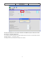
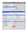
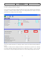
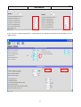
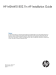
UNICALC 3.5
USER MANUAL
1
2
UNICALC 3.5 ............................................................................................................................................................. 1
USER MANUAL .......................................................................................................................................................... 1
START WINDOW ..................................................................................................................................................... 4
CLOSE CONTROL UNITS ...................................................................................................................................... 6
AIR CONDITIONING UNIT SELECTION WINDOW ............................................................................................................. 6
UNITS FAMILY UNICALC MAP .......................................................................................................................................... 7
SELECTION OF AN AIR CONDITIONING - DIRECT EXPANSION UNIT - AIR COOLED ........................................................... 8
SELECTION OF AN AIR CONDITIONING DIRECT EXPANSION UNIT- WATER COOLED ..................................................... 10
SELECTION OF AN AIR CONDITIONING – ENERGY SAVING -TWIN COOL UNITS ............................................................. 12
AIR CONDITIONER CALCULATION WINDOWS ............................................................................................................... 14
HOT WATER RE-HEAT COIL CALCULATION WINDOW .................................................................................................... 16
TECHNICAL COOLING CHILLERS .....................................................................................................................17
COOLING SYSTEMS SELECTION WINDOW ..................................................................................................................... 17
CHILLERS SELECTION ..................................................................................................................................................... 17
HEAT PUMPS SELECTION............................................................................................................................................... 18
CHILLERS CALCULATION AT FULL LOAD CONDITIONS ................................................................................................... 20
CALCULATION OF THE COOLING CAPACITY AT PARTIAL LOAD ...................................................................................... 21
HEAT PUMPS CALCULATION ......................................................................................................................................... 23
FREE-COOLING CALCULATION ...................................................................................................................................... 25
UNIT WITH DIFFERENT CALCULATION MODE: BREC/F AND BCWC UNITS ............................................26
CALCULATION OF THE NOMINAL COOLING CAPACITY .................................................................................................. 26
CALCULATION OF THE COOLING CAPACITY AT PARTIAL LOAD ...................................................................................... 34
CALCULATION OF THE COOLING CAPACITY IN FREE-COOLING...................................................................................... 37
UNIT WITH PARTICULAR CALCULATION MODE: ISAC/H/F AND ISCC/F/H UNITS...................................41
CALCULATION OF THE NOMINAL COOLING CAPACITY .................................................................................................. 41
CALCULATION OF THE COOLING CAPACITY AT PARTIAL LOAD ...................................................................................... 42
OTHER PROGRAM FUNCTIONS .........................................................................................................................47
CALCULATION REPORT .................................................................................................................................................. 47
NOISE DATA WINDOW .................................................................................................................................................. 48
ENERGY PERFORMANCE CALCULATION .......................................................................................................50
SINGLE UNIT CALCULATION .......................................................................................................................................... 51
REPORTS ....................................................................................................................................................................... 53
UNIT COMPARISON ....................................................................................................................................................... 54
PRINT REPORT ............................................................................................................................................................... 55
3
UNICALC 3.5
USER MANUAL
REV 1
START WINDOW
When you start the program, will appear on the screen a window where will be displayed a message
regarding the right to use this software
You can select between the following actions with a simple click on one of the windows’s pop up menu:
1) close the program
2) select the language: the program will use your selected language from this point on; the default language
is English
3) connect to the UNIFLAIR Europe internet site or send an e-mail to Uniflair;
4
UNICALC 3.5
USER MANUAL
REV 1
4) select between Cooling System Line, Precision Air Conditioning Line and Energy Performance
Calculation. Choosing one of the proposed lines, you will approach to the next window where you will be
able to select the unit and find out his thermodynamics performance.
5
UNICALC 3.5
USER MANUAL
REV 1
CLOSE CONTROL UNITS
AIR CONDITIONING UNIT SELECTION WINDOW
This window enables selection of macrofamily(1), power supply(2) (if more than one option is available), unit
series(3), unit model(4), air pattern(4), refrigerant o glycol type(5), unit model(6), remote air-cooled
condenser or water cooled condenser (if specified), accessories (8), calculation options. The example given
shows an air conditioning unit and so not all the options shown will be available for other unit
1
2
3
4
5
6
8
6
REV 1
UNICALC 3.5
USER MANUAL
UNITS FAMILY UNICALC MAP
Macro Family
Unit series
Chiller water units
Single coil
Amico CW
SDCC,SDCV
Leonardo CW
TDCR,TDCV
Leonardo Max CW
TDCR,TDCV
Leonardo CW
TDCR,TDCV
Leonardo Max CW
TDCR,TDCV
Amico DXa
SDAC, SDAV
Leonardo DXa
TDAR, TDAV
Leonardo Max DXa
TDAR, TDAV
Amico DXw
SDWC, SDWV
Leonardo DXw
TDWR, TDWV
Leonardo Max DXw
TDWR, TDWV
Leonardo DXe
TDER, TDEV
Leonardo Max DXe
TDER, TDEV
Twin cool - air cooled
Leonardo CW-DXa
TDTR, TDTV
cond.
Leonardo Max CW-DXa
TDTR, TDTV
Twin cool - Water cooled
Leonardo CW-DXw
TDDR, TDDV
condenser
Leonardo Max CW- DXw
TDDR, TDDV
Dual coil
Direct expansion units
Air cooled condenser
Water cooled condenser
Energy
saving-
Twin
Energy saving
cool units
7
UNICALC 3.5
USER MANUAL
REV 1
SELECTION OF AN AIR CONDITIONING - DIRECT EXPANSION UNIT - AIR COOLED
For this type of air conditioner you can select:
1. unit macrofamily: click on an item on the selection list at the top left;
2. unit power supply (mains voltage, frequency, number of phases); only displayed where more than one
option is available. Where a choice is given, click on the required option;
3. unit series: click on an item on the selection list at the bottom of the unit macrofamily;
4. air pattern:
5. refrigerant: only displayed where more than one option is available. Click with the left mouse button to
choose the required option on the pop-up menu;
6. unit model: click on an item in the selection list at the center;
7. remote condenser unit suggested for the selected unit.
8. accessories: click on the features required. The selection of some accessories may automatically
exclude others.
8
UNICALC 3.5
USER MANUAL
REV 1
At the end of the selection of the unit you can reach the performance calculation window through the
toolbar button.
You can return to the main start window with a simple click of toolbar button
9
UNICALC 3.5
USER MANUAL
REV 1
SELECTION OF AN AIR CONDITIONING DIRECT EXPANSION UNIT- WATER
COOLED
For this type of air conditioner you can select:
1. unit macrofamily: click on an item on the selection list at the top left;
2. unit power supply (mains voltage, frequency, number of phases); only displayed where more than one
option is available. Where a choice is given, click on the required option;
3. unit series: click on an item on the selection list at the bottom of the unit macrofamily;
4. air pattern:
5. refrigerant: only displayed where more than one option is available. Click with the left mouse button to
choose the required option on the pop-up menu;
6. unit model: click on an item in the selection list at the center;
7. External rad cooler. With a click on the rad-cooler check box will appear a list of rad-cooler for the
selected unit. This type of unit allows the selection of the number of air conditioner and the number of
rad-cooler.
10
UNICALC 3.5
USER MANUAL
REV 1
8. accessories: click on the features required. The selection of some accessories
9. function parameters (water side): these include calculation with constant water thermal jump or with
constant water flow.
At the end of the selection of the unit you can reach the performance calculation window through the
toolbar button.
You can return to the main start window with a simple click of toolbar button
11
UNICALC 3.5
USER MANUAL
REV 1
SELECTION OF AN AIR CONDITIONING – ENERGY SAVING -TWIN COOL UNITS
In this window you can select:
1. unit macrofamily: click on an item on the selection list at the top left;
2. unit power supply (mains voltage, frequency, number of phases); only displayed where more than one
option is available. Where a choice is given, click on the required option;
3. unit series: click on an item on the selection list at the bottom of the unit macrofamily;
4. air pattern:
5. refrigerant: only displayed where more than one option is available. Click with the left mouse button to
choose the required option on the pop-up menu;
6. unit model: click on an item in the selection list at the center;
7. External rad cooler. With a click on the rad-cooler check box will appear a list of rad-cooler for the
selected unit. This type of unit allows the selection of the number of air conditioner and the number of
rad-cooler.
8. accessories: click on the features required. The selection of some accessories may automatically
exclude others;
12
UNICALC 3.5
USER MANUAL
REV 1
9. function parameters (water side): these include calculation with constant water thermal jump or with
constant water flow. Click on the water-cooled condenser pop-up menu;
At the end of the selection of the unit you can reach the performance calculation window through the
toolbar button.
You can return to the main start window with a simple click of toolbar button
13
UNICALC 3.5
USER MANUAL
REV 1
AIR CONDITIONER CALCULATION WINDOWS
EXAMPLE - DIRECT EXPANSION UNIT - AIR COOLED
This screen allows the user to enter the required function conditions and calculate unit performance, based
on the unit parameters already selected: input parameters have a blue background, whereas performance
data have numerical boxes with a white background).
It is possible to choose either default or modified function parameters; values can be entered directly in the
light blue numbered boxes and this action will cause the blanking of all white numbered boxes.
With a simple click on the
toolbar button Performance data is calculated by the program and shown in
the white numbered boxes.
Alternatively scrolling bar will appear by double clicking (using the left-side button of your mouse) on the light
blue numerical box in which, by changing the position of the cursor, it is possible to change the data of the
parameter selected.. In this case the performance figures are updated clicking OK button;
14
REV 1
UNICALC 3.5
USER MANUAL
If you have select hot water re-heat option in the previous selection window the toolbar button
This button allow you to access the hot water re-heat coil calculation screen;
To perform a calculation in dehumification operating you can click the
figures are updated automatically.
Click the
is enabled.
toolbar button. In this case the performance
toolbar button to open the print window and see the preview of the calculations report.
If available for the selected unit, you can open a noise data window using the
You can return to the selection window with a simple click of toolbar button
15
toolbar button.
UNICALC 3.5
USER MANUAL
REV 1
HOT WATER RE-HEAT COIL CALCULATION WINDOW
This window can be accessed only if an air conditioning unit with the hot water re-heat option has been
selected. It is possible to choose either default or modified function parameters; values can be entered
directly in the light blue numbered boxes. Performance data is calculated by the program and shown in the
white numbered boxes. Alternatively double-click on the box to show a sliding scale which changes the
parameter value. In both cases the performance figures are updated dynamically;
Passing the cursor over a numbered box or text bring up a short description of that object at the bottom of
the screen
Click the
toolbar button to open the print window and see the preview of the complete calculation
report.
You can return to the main calculation window with a simple click of toolbar button
16
UNICALC 3.5
USER MANUAL
REV 1
TECHNICAL COOLING CHILLERS
COOLING SYSTEMS SELECTION WINDOW
this enables selection of unit family, model, power supply (if more than one option is available), refrigerant
and any calculation options.
Using the pop up menu on the top of the window it is possible to apply a filter in order to see chillers or heat
pumps only.
CHILLERS SELECTION
17
UNICALC 3.5
USER MANUAL
REV 1
This window enables selection of:
1. unit family: click on an item on the selection list at the top left; Using the pop up menu on the top of the
window it is possible to apply a filter in order to see chillers or heat pumps only.
2. unit model: click on an item in the selection list at the top right;
3. unit power supply (mains voltage, frequency, number of phases); only displayed where more than one
option is available. Where a choice is given, click on the required option;
4. Passing the cursor over an object will bring up a short description of that object at the bottom of the
screen .
5. At the end of the selection of the unit you can reach the performance calculation window through the
toolbar button.
6. You can return to the main start window with a simple click of toolbar button
HEAT PUMPS SELECTION
18
REV 1
UNICALC 3.5
USER MANUAL
This window enables selection of:
1. unit family: click on an item on the selection list at the top left; Using the pop up menu on the top of the
window it is possible to apply a filter in order to see chillers or heat pumps only.
2. unit model: click on an item in the selection list at the top right;
3. unit power supply (mains voltage, frequency, number of phases); only displayed where more than one
option is available. Where a choice is given, click on the required option;
4. winter or summer function mode, selectable from the pop-up menu; By default “summer operation” is
proposed so with a click on
button the program will show the summer operation calculation
window; by returning to the selection window
it is possible to perform the calculation in the other
function ( eg. Winter operation):
in order to apply this sequence of calculation (summer operation + winter operation) it is recommended
to do not deselect the conditioning model and press on the
button: in this way the second
calculation chart (summer function) will include values and input parameters that have already been
inserted in the first calculation chart (winter function) that normally remain or have to remain unchanged
even in the other operating mode for example; waterflow, altitude, percentage of glycol and the
possibility of air counter-pressure;
Passing the cursor over an object will bring up a short description of that object at the bottom of the
screen .
At the end of the selection of the unit you can reach the performance calculation window through the
toolbar button.
You can return to the main start window with a click of toolbar button
19
UNICALC 3.5
USER MANUAL
REV 1
CHILLERS CALCULATION AT FULL LOAD CONDITIONS
this procedure is not valid for the following series, which are described in the following sections:
•
BREC/F
•
BCWC
•
ISAC/H/F
•
ISCC/H/F
This screen allows the user to enter the required operating conditions and calculate unit performance, based
on the unit parameters already selected for chiller unit or for Heat pump unit in summer operating mode.
It is possible to choose either default or modified function parameters; values can be entered directly in the
light blue numbered boxes and this action will cause the blanking of all white numbered boxes.
With a simple click on the
toolbar button Performance data is calculated by the program and shown in
the white numbered boxes.
20
REV 1
UNICALC 3.5
USER MANUAL
Alternatively a scrolling bar will appear by double clicking (using the left-side button of your mouse) on the
light blue numerical box in which, by changing the position of the cursor, it is possible to change the data of
the parameter selected. In this case the performance figures are updated dynamically;
If you have select a freecooling chiller unit, the toolbar button
is enabled. This button allow you to
access the freecooling calculation screen;
If available for the selected unit, you can open a noise data window using the
Click the
toolbar button.
toolbar button to open the print window and see the preview of the calculations report.
With a simple click of toolbar button
,you can return to the selection window in order to select a new
model or a different family unit or in order to perform the winter operating mode calculations of a heat pump
of which the “summer” performance has already been calculated.
CALCULATION OF THE COOLING CAPACITY AT PARTIAL LOAD
Starting with the version 3.4.6, the Unicalc software allows calculation of the performance of some units in
different conditions of cooling capacity as required.
This possibility can be used to calculate the performance conditions at partial load.
It is necessary to underline that the performances must be calculated with constant water flow rate, thereby
using the same real operating conditions.
In the principal display it is therefore necessary to select the corresponding option (“water outlet temperature
and water cooling flow rate are known”).
21
UNICALC 3.5
USER MANUAL
REV 1
For the simulations of the units BRA*, ERA* and ERC* where it is possible to modulate the cooling capacity
by simulating the shutdown of one or more compressors.
22
UNICALC 3.5
USER MANUAL
REV 1
HEAT PUMPS CALCULATION
this procedure is not valid for ISAC/H/F and ISCC/H/F series, which are described in the following sections:
23
REV 1
UNICALC 3.5
USER MANUAL
This screen allows the user to enter the required operating conditions and calculate unit performance, based
on the unit parameters already selected for chiller unit or for Heat pump unit in summer operating mode.
It is possible to choose either default or modified function parameters; values can be entered directly in the
light blue numbered boxes and this action will cause the blanking of all white numbered boxes.
With a simple click on the
toolbar button Performance data is calculated by the program and shown in
the white numbered boxes.
Alternatively a scrolling bar will appear by double clicking (using the left-side button of your mouse) on the
light blue numerical box in which, by changing the position of the cursor, it is possible to change the data of
the parameter selected. In this case the performance figures are updated dynamically;
If available for the selected unit, you can open a noise data window using the
Click the
toolbar button.
toolbar button to open the print window and see the preview of the calculations report.
With a simple click of toolbar button
,you can return to the selection window in order to select a new
model or a different family unit or in order to perform the summer operating mode calculations of a heat
pump of which the “winter” performance has already been calculated.
24
UNICALC 3.5
USER MANUAL
REV 1
FREE-COOLING CALCULATION
this procedure is not valid for BREF, ISAF and ISCF series, which are described in the following sections:
This screen is only displayed if a Free Cooling unit has been selected and if the relevant button was pressed
in the chiller calculation window. It enables:
It is possible to choose either default or modified function parameters; values can be entered directly in the
light blue numbered boxes. Alternatively a scrolling bar will appear by double clicking (using the left-side
button of your mouse) on the light blue numerical box in which, by changing the position of the cursor, it is
possible to change the data of the parameter selected. In both cases the performance figures are updated
dynamically;
Click the
toolbar button to open the print window and see the preview of the complete calculation
report
25
REV 1
UNICALC 3.5
USER MANUAL
UNIT WITH DIFFERENT CALCULATION MODE: BREC/F and
BCWC units
CALCULATION OF THE NOMINAL COOLING CAPACITY
In the principal display it is possible to select the units and their configurations. In this way, it is possible to
select:
A. Type of glycol with which to carry out the simulation:
a. Ethylene
b. Propylene
B. Selection of the operating parameters:
a. Outlet and inlet water temperature are known
b. Outlet water temperature and water flow are known
c. Inlet water temperature and water flow are known
1
C. High external temperature - High condensing temperature (*)
D. Economizer
E. Pumps group on board the unit:
a. 1 pump
b. 1+1 pumps
F. Partial heat recovery
G. Fan(s) type selection:
a. Acousti-composite axial fans
b. Acousti-composite axial fans with EC motor
H. Options
a. Low ambient temperature
b. Water production at low temperature
I.
Version
a. Low noise
b. Ultra low noise
1
This option is standard for BREC/F units, models 1602A, 1802A, 2202A, 2502A and 2802A
26
REV 1
UNICALC 3.5
USER MANUAL
A
E
I
F
C
D
H
G
B
Simulation of the BREC/F units, allows simulation of the operation in different conditions other than just
temperature and set-point, also thermal capacity.
A. Thermal load to dissipate
B. Cooling capacity of the unit
C. Maximum cooling capacity of the unit with the set conditions (air temperature, water and
glycol percentage)
27
UNICALC 3.5
USER MANUAL
REV 1
A
B
C
The simulation calculates the operation at the requested cooling capacity. Therefore, the reported data
(electrical absorption, loss of load…) refers to this value.
If the requested cooling capacity is lower than the maximum value supplied by the unit in the set conditions,
operation will be at partial load. Included in the recorded data therefore, there is also the percentage time
based average of the compressors’ operation.
28
UNICALC 3.5
USER MANUAL
REV 1
In the event of a request to calculate the characteristics of the unit while it is supplying the maximum cooling
capacity in nominal conditions, it is necessary to insert the maximum value and proceed with the calculation.
In the event a value above the maximum is inserted, the selection software generates an error message and
proposes the maximum value.
In the following examples simulations are considered for a BREC 1802A, in the conditions indicated, this unit
can supply a maximum 458kW, and with this value, if inserted as “target cooling capacity”, the calculation is
performed. If, however, a value of 500kW is inserted, a warning message is displayed and the software
proceeds with a calculation for 458kW (see following example).
If the required cooling capacity is lower than the maximum value supplied by the unit in the set conditions,
operation will be at partial load. Included in the recorded data therefore, there is also the operating
percentage of the compressors.
In the event the cooling capacity is lower than the maximum, it is therefore possible to decide selection of the
unit with the maximum power supplied, highlighting this last point, or selecting the required capacity,
highlighting energy efficiency.
29
UNICALC 3.5
USER MANUAL
30
REV 1
UNICALC 3.5
USER MANUAL
REV 1
The same considerations are also valid for simulation of the BCWC unit (water cooled water chillers
with “Oil free” centrifugal compressors).
The simulation calculates operation at the required cooling capacity. Therefore, the recorded data (electrical
absorption, load loss…) refer to these values.
The display shows the percentage of the compressor/s capacity.
31
UNICALC 3.5
USER MANUAL
REV 1
If the required cooling capacity is lower than the maximum value supplied by the unit in the set conditions,
operation will be at partial load. Included in the recorded data therefore, there is also the operating
percentage of the compressors.
In the event the cooling capacity is lower than the maximum it is therefore possible to decide selection of the
unit with the maximum power supplied, highlighting this last point, or selecting the required capacity,
highlighting energy efficiency.
32
UNICALC 3.5
USER MANUAL
33
REV 1
UNICALC 3.5
USER MANUAL
REV 1
CALCULATION OF THE COOLING CAPACITY AT PARTIAL LOAD
Starting with the version 3.4.6, the Unicalc software allows calculation of the performance of some units in
different conditions of cooling capacity as required.
This possibility can be used to calculate the performance conditions at partial load.
It is necessary to underline that the performances must be calculated with constant water flow rate, thereby
using the same real operating conditions.
In the principal display it is therefore necessary to select the corresponding option (“water outlet temperature
and water cooling flow rate are known”).
In this way it is possible to calculate the performance at any desired load condition.
Included in the recorded data therefore, there is also the percentage time based average of the operation of
the compressors.
34
UNICALC 3.5
USER MANUAL
REV 1
The same considerations are also valid for the simulation of the BCWC unit.
It is necessary to underline that the performances must be calculated with constant water flow rate, thereby
using the same real operating conditions both for the condenser and the evaporator.
In the principal display it is therefore necessary to select the corresponding option (“water outlet temperature
and water cooling flow rate are known for the evaporator” and “water inlet temperature and water cooling
flow rate are known for the condenser”).
35
UNICALC 3.5
USER MANUAL
36
REV 1
UNICALC 3.5
USER MANUAL
REV 1
CALCULATION OF THE COOLING CAPACITY IN FREE-COOLING
Starting with the version 3.4.6 the Unicalc selection software allows the calculation of the cooling capacity for
units supplied with a free-cooling system in all states of operation.
A. Mechanical cooling
B. Mixed Free-cooling
C. Total free-cooling
For the selection in mechanical cooling the same considerations are valid as for the air cooled unit, while for
the performance calculation of systems with free-cooling activated it is necessary to follow the example
below.
It is first necessary to underline that the performances must be calculated with constant water flow rate,
thereby using the same real operating conditions.
In the principal display it is therefore necessary to select the corresponding option (“water outlet temperature
and water cooling flow rate are known”).
37
UNICALC 3.5
USER MANUAL
REV 1
For selection in mechanical cooling the same considerations are valid as for the air cooled units with the
difference that the nominal starting conditions are different.
In fact, a general design policy for data centres, with the aim of reducing energy consumption, is that of
optimizing available resources, increasing the cooling capacity in free-cooling the chillers supplied with this
system are defined with cooled water temperature above the “classic” 7°C.
For this reason, the technical data relative to the chillers supplied with free-cooling are declared with
an inlet and outlet water temperature, of not more than 12/7°C, but rather 15/10°C.
With the exception of this difference, the simulation is carried out in accordance with the same method.
N.B. In the simulation display the temperature is recorded at which the unit reaches total free-cooling
(complete shutdown of the compressors).
38
UNICALC 3.5
USER MANUAL
REV 1
Inserting the external air temperature values lower than the nominal it is possible to simulate the operation of
the chillers according to the different conditions.
In the event of the air temperature possibly being lower by 2°C of the return temperature of the chilled water,
free-cooling is activated and both capacities (part of the cooling provided by the compressors and part
provided by the free-cooling circuit) can be calculated.
Also for the methods of operation in free-cooling the software calculates the different operating conditions for
the unit.
During these methods (mixed free-cooling) the air flow rate, and therefore the speed of the fans is limited by
the minimum admissible condensation temperature for the cooling circuit. Therefore, as much as possible,
the unit, tends to use only one cooling circuit in order to “free” the free-cooling exchangers from such limits.
39
UNICALC 3.5
USER MANUAL
REV 1
In the event, the external temperature is sufficiently low, the complete thermal load is dissipated by the freecooling circuit.
40
REV 1
UNICALC 3.5
USER MANUAL
UNIT WITH PARTICULAR CALCULATION MODE: ISAC/H/F and
ISCC/F/H units
CALCULATION OF THE NOMINAL COOLING CAPACITY
In the principal display it is possible to select the units and their configurations. In this way, it is possible to
select:
J. Type of glycol with which to carry out the simulation:
a. Ethylene
b. Propylene
K. Selection of the operating parameters:
a. Outlet and inlet water temperature are known
b. Outlet water temperature and water flow are known
c. Inlet water temperature and water flow are known
L. Pumps group on board the unit:
a. 1 pump
b. 1+1 pumps
C
A
B
41
REV 1
UNICALC 3.5
USER MANUAL
Simulation of the ISA* and ISC* units, allows simulation of the operation in different conditions other than just
temperature and set-point, also thermal capacity.
D. Thermal load to dissipate (not enable for full load calculation)
E. Cooling capacity of the unit
A
B
CALCULATION OF THE COOLING CAPACITY AT PARTIAL LOAD
Starting with the version 3.4.6, the Unicalc software allows calculation of the performance of some units in
different conditions of cooling capacity as required.
This possibility can be used to calculate the performance conditions at partial load.
It is necessary to underline that the performances must be calculated with constant water flow rate, thereby
using the same real operating conditions.
In the principal display it is therefore necessary to select the corresponding option (“water outlet temperature
and water cooling flow rate are known”).
42
UNICALC 3.5
USER MANUAL
REV 1
In this way it is possible to calculate the performance at any desired load condition.
The simulation calculates the operation at the requested cooling capacity. Therefore, the reported data
(electrical absorption, loss of load…) refers to this value.
If the requested cooling capacity is lower than the maximum value supplied by the unit in the set conditions,
operation will be at partial load.
43
UNICALC 3.5
USER MANUAL
44
REV 1
UNICALC 3.5
USER MANUAL
45
REV 1
UNICALC 3.5
USER MANUAL
46
REV 1
UNICALC 3.5
USER MANUAL
OTHER PROGRAM FUNCTIONS
CALCULATION REPORT
The user can export the report data as an HTML (internet) or TXT (text) file.
The user can print the report data.
In order to return to the main calculation window is necessary to use the pop up menu “BACK”
47
REV 1
UNICALC 3.5
USER MANUAL
REV 1
NOISE DATA WINDOW
This can be accessed only from the other program functions window and is used to:
1. display a table with the free field sound spectrum(s) of the chosen unit (SPL distribution in dB at the
various emission frequencies);
2. indicate the equivalent free-field sound pressure level(s) in dBA for the selected unit;
3. display a graph of the free-field sound spectrum(s) for the selected unit (SPL distribution in dB at the
various emission frequencies). The graph can be shown in 3D by clicking on the relevant button.
48
UNICALC 3.5
USER MANUAL
REV 1
The graph can also be rotated: hold down the Ctrl button on the computer and the left mouse button and
move the mouse to turn the graph; for units with no available sound spectrum data this window is smaller
and contains no
Click the
toolbar button to print the screen.
49
UNICALC 3.5
USER MANUAL
REV 1
ENERGY PERFORMANCE CALCULATION
With the 3.5.1 version of Unicalc, it is now possible to simulate the energy performance of computer room air
conditioning units and BREC/F large chillers.
In this way it is possible to compare different technical solutions and / or configurations.
It is possible to select this function on the main menu of the first screen:
A. Computer room air conditioning units range
B. Large chiller range
A
B
50
UNICALC 3.5
USER MANUAL
REV 1
SINGLE UNIT CALCULATION
It is possible to calculate the yearly energy consumption for a specific unit / configuration.
On the INPUT 1/2 screen it is possible to select the units (series, models, filters…) and the site operating
configuration (number of operating units / stand-by units, required cooling capacity…).
By inserting the required capacity and the number of operating units it is possible to simulate part load
conditions or load sharing conditions.
On the INPUT 2/2 screen it is possible to select the climatic profile for the site location and the energy cost
per kWh (A).
If there isn’t a climatic profile which reflects the site conditions, it is possible to insert a new one (B).
51
REV 1
UNICALC 3.5
USER MANUAL
B
A
Once the installation features has been set, it is possible to insert the operating conditions for the units, such
as the dry and web bulb temperatures, the external static pressure and so on…
When carrying out a chiller simulation it is necessary to insert the data specific to a chiller such as the chilled
water temperature, the glycol percentage, the nominal water flow, etc.
One the input section is complete, click on the “calculate” button, a bar will appear which indicates the
calculation process.
52
UNICALC 3.5
USER MANUAL
REPORTS
The results are spread over 4 screens which can be selected by the tabs at the top of the screen.
•
Screen 1: summary data
•
Screen 2: detailed breakdown
•
Screen 3: chart showing the annual energy consumption
•
Screen 4: chart showing the annual energy cost
53
REV 1
UNICALC 3.5
USER MANUAL
REV 1
UNIT COMPARISON
In the event of a direct comparison between two different units / configurations, these screens also show the
difference in energy consumption and energy cost.
In the example below a comparison between a free-cooling chiller and a standard on is shown.
In the main screen the energy saving is reported as well as the summary data for the units, while the other
screen show the detailed data and charts.
54
UNICALC 3.5
USER MANUAL
REV 1
PRINT REPORT
It is possible to print a general overview or all of the detailed information by ticking the appropriate boxes.
55
UNICALC 3.5
USER MANUAL
REV 1
At this stage it is possible to generate a print-out or, if a pdf printer is installed on your PC, the report can be
saved as a .pdf file.
56
UNICALC 3.5
USER MANUAL
57
REV 1
58