1
User's
Manual
Model ZR22G, ZR402G
Separate type
Zirconia High Temperature Humidity Analyzer
IM 11M12A01-03E
IM 11M12A01-03E
7th Edition
Introduction
The EXAxt ZR Separate-type Zirconia High-temperature Humidity Analyzer has been
developed for humidity control in various industrial processes. This analyzer basically
consists of a detector and a converter. You can select between several versions based
upon your application.
Optional accessories are also available to improve measurements and automate calibration. An optimal control system can be realized by adding appropriate options.
This instruction manual refers to almost all of the equipment related to the EXAxt ZR.
You may skip any section(s) on the equipment which is/are not included in your system.
Regarding the HART communication protocol,refer to the IM 11M12A01-51E.
IM 11M12A01-51E has been published as Model EXAxt ZR Series HART Protocol
The all-in-one version (with sensor and analyzer integrated in one body) is described in
IM 11M12A01-05E
< Before using the equipment, please read any related descriptions in this manual for the
equipment and the system you have, on appropriate use and operation of the EXAxt ZR. >
Models and descriptions in this manual are as follows:
Models and descriptions in this manual
Model
ZR22G
ZR402G
ZH21B
ZA8F
ZR40H
ZO21S
Product Name
General-use detector
Converter
Dust protector
Flow setting unit (for manual calibration use)
Automatic Calibration unit
Calibration gas unit case (Part No. E7044KF)
Check valve (Part No. K9292DN, K9292DS)
Standard gas unit
Specification
s
s
s
s
s
s
s
Description in this manual
Installation Operation Maintenance CMPL
s
s
s
s
s
s
s
s
s
s
s
s
s
s
s
s
s
s
s
T.Int.1E
CMPL : Customer Maintenance Parts List
IM 11M12A01-03E
7th Edition: Sep. 2006 (YK)
All Rights Reserved, Copyright © 2000, Yokogawa Electric Corporation
IM 11M12A01-03E
i
This manual consists of twelve chapters. Please refer to the reference chapters for
installation, operation and maintenance.
Table of Contents
Chapter
Outline
1. Overview
Equipment models and system configuration examples
2. Specifications
Standard specification, model code (or part number),
3. Installation
dimension drawing for each equipment
Installation method for each equipment
4. Piping
Examples of piping in three standard system
5. Wiring
configurations
Wiring procedures such as Power supply wiring , output
signal wiring or others
6. Components
7. Startup
These are described in this manual
Basic procedure to start operation of EXAxt ZR. Chapter 7
Installation
References
Operation Maintenance
s
n
s
s
s
s
s
n
s
n
s
n
n
s
s
s
enables you to operate the equipment immediately.
8. Detailed Data Setting
Details of key operations and displays
s
n
9. Calibration
Describes the calibration procedure required in the course
of operation.
s
n
10. Other Functions
11. Inspection and
Maintenance
Other functions described
How to conduct maintenance of EXAxt ZR and procedures
for replacement of deteriorated parts
s
n
s
s
12. Troubleshooting
This chapter describes measures to be taken when an
n
s
CMPL (parts list)
abnormal condition occurs.
User replaceable parts list
n
s
s : Read and completely understand before operating the equipment.
s : Read before operating the equipment, and refer to whenever necessary.
n : Recommended to read it at least once.
ii
n
T.Int.2E
IM 1M12A01-03E
r For the safe use of this equipment
CAUTION
The cell (sensor) at the tip of the detector is made of ceramic (zirconia element). Do not
drop the detector or subject it to pressure stress.
• Do NOT allow the sensor (probe tip) to make contact with anything when installing
the detector.
• Avoid any water dropping directly on the probe (sensor) of the detector when installing it.
• Check the calibration gas piping before introducing the calibration gas to ensure that
there is no leakage of the gas. If there is any leakage of the gas, the moisture drawn
from the measuring gas can damage the sensor.
• The detector (especially at the tip) becomes very hot. Be sure to handle it with gloves.
EXAxt ZR is very heavy. Handle it with care. Be sure not to accidentally drop it.
Handle safely to avoid injury.
DANGER
Connect the power supply cord only after confirming that the supply voltage matches
the rating of this equipment. In addition, confirm that the power is switched off when
connecting power supply.
Some process gas is dangerous to people. When removing this equipment from the
process line for maintenance or other reasons, protect yourself from potential
poisoningby using a protective mask or ventilating the area well.
(1) About This Manual
• This manual should be passed on to the end user.
• The contents of this manual are subject to change without prior notice.
• The contents of this manual shall not be reproduced or copied, in part or in whole,
without permission.
• This manual explains the functions contained in this product, but does not warrant that
those will suit the particular purpose of the user.
• Every effort has been made to ensure accuracy in the preparation of this manual.
However, should any errors or omissions come to the attention of the user, please
contact the nearest Yokogawa Electric representative or sales office.
• This manual does not cover the special specifications. This manual may not be
changed on any change of specification, construction and parts when the change does
not affect the functions or performance of the product.
• If the product is used in a manner not specified in this manual, safety of this product
may be impaired.
IM 11M12A01-03E
iii
(2) Safety and Modification Precautions
• Follow the safety precautions in this manual when using the product to ensure protection and safety of personnel, product and system containing the product.
(3) The following safety symbols are used on the product as well as in this manual.
DANGER
This symbol indicates that the operator must follow the instructions laid out in this
manual in order to avoid the risk of personnel injuries or fatalities such as electric shock.
The manual describes what special care the operator must exercise to prevent such risks.
WARNING
This symbol indicates that the operator must refer to the instructions in this manual in
order to prevent the instrument (hardware) or software from being damaged, or a system
failure from occurring.
CAUTION
This symbol draws attention to information essential for understanding the operation and
functions.
Tip
This symbol gives information that complements the present topic.
SEE ALSO
This symbol identifies a source to which to refer.
Protective Ground Terminal
Function Ground Terminal (Do not use this terminal as the protective ground
terminal.)
Alternating current
iv
IM 1M12A01-03E
• Special descriptions in this manual
This manual indicates operation keys, displays and drawings on the product as follows:
• Operation keys, Enclosed in [ ], displays on the panel 0 0.
(Ex. [MODE] key)
(Ex. message display
(Ex. data display
0 BASE 0)
0 102 0 lit, 0 102 0 flashing)
• Drawing for flashing
Indicated by gray characters. (Flashing)
IM 11M12A01-03E
(lit)
v
r NOTICE
• Specification check
When the instrument arrives, unpack the package with care and check that the
instrument has not been damaged during transportation. In addition, please check that
the specification matches the order, and required accessories are not missing. Specifications can be checked by the model codes on the nameplate. Refer to Chapter 2
Specifications for the list of model codes.
• Details on operation parameters
When the EXAxt ZR Separate-type High Temperature Humidity Analyzer arrives at
the user site, it will operate based set before shipping parameters (initial data) on the
departure from the factory.
Ensure that the initial data is suitable for the operation conditions before conducting
analysis. Where necessary, set the instrument parameters for appropriate operation.
For details of setting data, refer to chapters 7 to 10.
When user changes the operation parameter, it is recommended to note down the
changed setting data.
r After-Sales Warranty
d Do not modify the product.
d During the warranty period, for repair under warranty carry or send the product to the
local sales representative or service office. Yokogawa will replace or repair any
damaged parts and return the product to you.
d Before returning a product for repair under warranty, provide us with the model
name and serial number and a description of the problem. Any diagrams or data
explaining the problem would also be appreciated.
d If we replace the product with a new one, we won’t provide you with a repair report.
d Yokogawa warrants the product for the period stated in the pre-purchase quotation.
Yokogawa shall conduct defined warranty service based on its standard. When the
customer site is located outside of the service area, a fee for dispatching the maintenance engineer will be charged to the customer.
d In the following cases, customer will be charged repair fee regardless of warranty
period.
• Failure of components which are out of scope of warranty stated in instruction
manual.
• Failure caused by usage of software, hardware or auxiliary equipment, which
Yokogawa Electric did not supply.
• Failure due to improper or insufficient maintenance by user.
• Failure due to modification, misuse or outside-of-specifications operation which
Yokogawa does not authorize.
• Failure due to power supply (voltage, frequency) being outside specifications or
abnormal.
• Failure caused by any usage out of scope of recommended usage.
• Any damage from fire, earthquake, storms and floods, lightning, disturbances, riots,
warfare, radiation and other natural changes.
vi
IM 1M12A01-03E
d Yokogawa does not warrant conformance with the specific application at the user
site. Yokogawa will not bear direct/indirect responsibility for damage due to a specific
application.
d Yokogawa Electric will not bear responsibility when the user configures the product
into systems or resells the product.
d Maintenance service and supplying repair parts will be covered for five years after
the production ends. For repair for this product, please contact the nearest sales office
described in this instruction manual.
IM 11M12A01-03E
vii
Contents
Introduction ........................................................................................................................... i
r For the safe use of this equipment ............................................................................... iii
r NOTICE ......................................................................................................................... vi
r After-Sales Warranty ................................................................................................... vi
1. Overview ...................................................................................................................... 1-1
1.1
< EXAxt ZR > System Configuration ............................................................
1.1.1 System 1 ..................................................................................................
1.1.2 System 2 ..................................................................................................
1.1.3 System 3 ..................................................................................................
1.2
< EXAxtZR > System Components ...............................................................
1.2.1 System Components ................................................................................
1.2.2 Detectors and Accessories .......................................................................
1-2
1-2
1-3
1-4
1-5
1-5
1-5
2. Specifications ............................................................................................................... 2-1
2.1
General Specifications .................................................................................... 2-1
2.1.1 Standard Specifications ........................................................................... 2-1
2.2
General-use Separate-type Detector and Related Equipment ........................ 2-3
2.2.1 ZR22G General-use Separate-type Detector ........................................... 2-3
2.2.2 ZH21B Dust Protector ............................................................................. 2-8
2.3
ZR402G Separate-type Converter ................................................................... 2-9
2.3.1 Standard Specifications ........................................................................... 2-9
2.3.2 Function ................................................................................................. 2-10
2.4
ZA8F Flow Setting Unit and ZR40H Automatic Calibration Unit ............. 2-16
2.4.1 ZA8F Flow Setting Unit ........................................................................ 2-16
2.4.2 ZR40H Automatic Calibration Unit ...................................................... 2-18
2.5
ZO21S Standard Gas Unit ............................................................................ 2-21
2.6
Other Equipment ........................................................................................... 2-22
2.6.1 Stop Valve (Part Number: L9852CB or G7016XH) ............................ 2-22
2.6.2 Check Valve (Part Number: K9292DN or K9292DS) ......................... 2-23
2.6.3
Air Set ................................................................................................... 2-24
2.6.4 Zero-gas Cylinder (Part Number: G7001ZC) ....................................... 2-26
2.6.5
Pressure Regulator for Gas Cylinder
(Part Number: G7013XF or G7014XF) .............................................. 2-26
2.6.6
Case Assembly for Calibration-gas Cylinder
(Part Number: E7044KF) ..................................................................... 2-27
2.6.7 Model ZR22A Heater Assembly ........................................................... 2-28
3. Installation ................................................................................................................... 3-1
3.1
viii
Installation of the Detector .............................................................................
3.1.1 Location ...................................................................................................
3.1.2 Probe Insertion Hole ................................................................................
3.1.3 Installation of the Detector ......................................................................
3.1.4 Installation of ZH21B Dust Protector .....................................................
3-1
3-1
3-2
3-3
3-3
IM 1M12A01-03E
3.2
Installation of the Converter ........................................................................... 3-4
3.2.1
Location .................................................................................................. 3-4
3.2.2 Mounting of the Converter ...................................................................... 3-4
3.3
Installation of ZA8F Flow Setting Unit ......................................................... 3-7
3.3.1 Location ................................................................................................... 3-7
3.3.2 Mounting of ZA8F Flow Setting Unit .................................................... 3-7
3.4
Installation of ZR40H Automatic Calibration Unit ........................................ 3-9
3.4.1 Location ................................................................................................... 3-9
3.4.2 Mounting of ZR40H Automatic Calibration Unit .................................. 3-9
3.5
Installation of E7044KF Case Assembly for
the Calibration-gas Cylinder ......................................................................... 3-11
3.5.1 Location ................................................................................................. 3-11
3.5.2 Mounting ................................................................................................ 3-11
3.6
Insulation Resistance Test ............................................................................. 3-12
3.7
External Dimensions of Detectors with Pressure Compensation ................. 3-13
4. Piping ............................................................................................................................ 4-1
4.1
Piping for System 1 ........................................................................................ 4-1
4.1.1 Parts Required for Piping in System 1 ................................................... 4-2
4.1.2 Connection to the Calibration Gas Inlet ................................................. 4-2
4.1.3 Connection to the Reference Gas Inlet ................................................... 4-2
4.2
Piping for System 2 ........................................................................................ 4-3
4.2.1 Piping Parts for System 2 ........................................................................ 4-3
4.2.2 Piping for the Calibration Gas ................................................................ 4-4
4.2.3 Piping for the Reference Gas .................................................................. 4-4
4.3
Piping for System 3 ........................................................................................ 4-5
5. Wiring........................................................................................................................... 5-1
5.1
General ............................................................................................................ 5-1
5.1.1 Terminals for the External Wiring in the Converter .............................. 5-3
5.1.2 Wiring ...................................................................................................... 5-3
5.1.3 Mounting of Cable Gland ........................................................................ 5-4
5.2
Wiring for Detector Output ............................................................................. 5-5
5.2.1 Cable Specifications ................................................................................ 5-5
5.2.2 Connection to the Detector ...................................................................... 5-6
5.2.3 Connection to the Converter ................................................................... 5-7
5.3
Wiring for Power to Detector Heater ............................................................. 5-8
5.3.1 Cable Specifications ................................................................................ 5-8
5.3.2 Connection to Detector ............................................................................ 5-8
5.3.3 Connection to Converter ......................................................................... 5-9
5.4
Wiring for Analog Output ............................................................................. 5-10
5.4.1 Cable Specifications .............................................................................. 5-10
5.4.2 Wiring Procedure ................................................................................... 5-10
5.5
Power and Grounding Wiring ....................................................................... 5-11
5.5.1 Power Wiring ......................................................................................... 5-11
5.5.2 Grounding Wiring ................................................................................. 5-11
5.6
Wiring for Contact Output ............................................................................ 5-12
5.6.1 Cable Specifications .............................................................................. 5-12
5.6.2 Wiring Procedure ................................................................................... 5-12
5.7
Wiring for ZR40H Automatic Calibration Unit ........................................... 5-13
5.7.1 Cable Specifications .................................................................................. 5-14
5.7.2 Wiring Procedure ...................................................................................... 5-14
IM 11M12A01-03E
ix
5.8
Wiring for Contact Input ............................................................................... 5-15
5.8.1 Cable Specifications .............................................................................. 5-15
5.8.2 Wiring Procedure ................................................................................... 5-15
5.9
Temperature Input Wiring ............................................................................ 5-16
5.9.1 Applicable Temperature Transmitter .................................................... 5-16
5.9.2 Cable Specifications .............................................................................. 5-16
5.9.3 Wiring Procedure ................................................................................... 5-16
6. Components ................................................................................................................. 6-1
6.1
ZR22G Detector ..............................................................................................
6.1.1 General-purpose Detector ........................................................................
6.2
ZR402G Converter ..........................................................................................
6.3
ZA8F Flow Setting Unit, ZR40H Automatic Calibration Unit .....................
6-1
6-1
6-2
6-3
7. Startup .......................................................................................................................... 7-1
7.1
7.2
7.3
7.4
Checking Piping and Wiring Connections ..................................................... 7-1
Checking Valve Setup ..................................................................................... 7-1
Supplying Power to the Converter .................................................................. 7-2
Touchpanel Switch Operations ....................................................................... 7-3
7.4.1 Basic Panel and Switch ........................................................................... 7-3
7.4.2 Display Configuration (for High-temperature Humidity Analyzer) ....... 7-4
7.4.3 Display Functions .................................................................................... 7-5
7.4.4 Entering Numeric and Text Data ............................................................ 7-5
7.5
Confirmation of Converter Type Setting ........................................................ 7-7
7.6
Confirmation of Detector Type Setting .......................................................... 7-8
7.7
Current Output Setting .................................................................................... 7-8
7.7.1 Analog Output Setting ............................................................................. 7-8
7.7.2 Minimum Current (4 mA) and Maximum Current (20 mA) Settings ... 7-9
7.8
Setting Display Item ..................................................................................... 7-10
7.9
Checking Current Loop ................................................................................. 7-12
7.10 Checking Contact I/O ................................................................................... 7-13
7.10.1 Checking Contact Output ...................................................................... 7-13
7.10.2 Checking Calibration Contact Output ................................................... 7-14
7.10.3 Checking Input Contacts ....................................................................... 7-14
7.11 Calibration ..................................................................................................... 7-15
7.11.1 Calibration Setup ................................................................................... 7-15
7.11.2 Manual Calibration ................................................................................ 7-16
8. Detailed Data Setting .................................................................................................. 8-1
8.1
Current Output Setting ....................................................................................
8.1.1 About Input Ranges .................................................................................
8.1.2 Setting Minimum Current (4 mA) and Maximum Current (20 mA) .....
8.1.3 Entering Output Damping Constants ......................................................
8.1.4 Selection of Output Mode .......................................................................
8.1.5 Default Values .........................................................................................
8.2
Output Hold Setting ........................................................................................
8.2.1 Definition of Equipment Status ...............................................................
8.2.2 Preference Order of Output Hold Value .................................................
8.2.3 Output Hold Setting .................................................................................
8.2.4 Default Values .........................................................................................
x
8-1
8-1
8-4
8-4
8-4
8-5
8-6
8-6
8-7
8-8
8-8
IM 1M12A01-03E
8.3
Alarm Setting .................................................................................................. 8-9
8.3.1 Alarm Values ........................................................................................... 8-9
8.3.2 Alarm Output Actions ............................................................................. 8-9
8.3.3 Alarm Setting Procedure ....................................................................... 8-10
8.3.4 Default Values ....................................................................................... 8-11
8.4
Output Contact Setup .................................................................................... 8-12
8.4.1 Output Contact ....................................................................................... 8-12
8.4.2 Setting Procedure ................................................................................... 8-12
8.4.3 Default Values ....................................................................................... 8-15
8.5
Input Contact Settings ................................................................................... 8-16
8.5.1 Input Contact Functions ........................................................................ 8-16
8.5.2 Setting Procedure ................................................................................... 8-17
8.5.3 Default Values ....................................................................................... 8-17
8.6
Other Settings ................................................................................................ 8-18
8.6.1 Setting the Date-and-Time .................................................................... 8-18
8.6.2 Setting Periods over which Average Values Are Calculated and Periods over
which Maximum and Minimum Values Are Monitored ...................... 8-19
8.6.3 Setting Measurement Gas Temperature and Pressure .......................... 8-20
8.6.4 Setting Purging ...................................................................................... 8-22
8.6.5 Setting Passwords .................................................................................. 8-23
9. Calibration ................................................................................................................... 9-1
9.1
Calibration Briefs ............................................................................................ 9-1
9.1.1 Measurement Principle of Zirconia Humidity Analyzer ........................ 9-1
9.1.2 Calibration Gas ........................................................................................ 9-3
9.1.3 Compensation .......................................................................................... 9-4
9.1.4 Characteristic Data from a Sensor Measured During Calibration .......... 9-5
9.2
Calibration Procedures .................................................................................... 9-6
9.2.1 Calibration Setting ................................................................................... 9-6
9.2.2 Default Values ......................................................................................... 9-9
9.2.3 Calibration ............................................................................................. 9-10
10. Other Functions ........................................................................................................ 10-1
10.1 Display ........................................................................................................... 10-1
10.1.1 Detailed Display .................................................................................... 10-1
10.1.2 Trend Graph ........................................................................................... 10-5
10.1.3 Auto(matic) Display-Revert Time ......................................................... 10-7
10.1.4 Entering Tag Name ............................................................................... 10-8
10.1.5 Language Selection ............................................................................... 10-8
10.2 Blowback ....................................................................................................... 10-9
10.2.1 Blowback Setup ..................................................................................... 10-9
10.3 Operational Data Initialization .................................................................... 10-13
10.4 Reset ............................................................................................................ 10-17
10.5 Handling of the ZO21S Standard Gas Unit ................................................ 10-18
10.5.1 Standard Gas Unit Component Identification ..................................... 10-18
10.5.2 Installing Gas Cylinders ...................................................................... 10-19
10.5.3 Calibration Gas Flow ........................................................................... 10-20
10.6 Methods of Operating Valves in the ZA8F Flow Setting Unit .................. 10-23
10.6.1 Preparation Before Calibration ............................................................ 10-23
10.6.2 Operating the Span Gas Flow Setting Valve ...................................... 10-23
10.6.3 Operating the Zero Gas Flow Setting Valve ...................................... 10-24
10.6.4 Operation After Calibration ................................................................. 10-24
IM 11M12A01-03E
xi
11. Inspection and Maintenance .................................................................................... 11-1
11.1 Inspection and Maintenance of the Detector ................................................ 11-2
11.1.1 Cleaning the Calibration Gas Tube ....................................................... 11-2
11.1.2 Replacing the Sensor Assembly ............................................................ 11-3
11.1.3 Replacement of the Heater Unit .......................................................... 11-5
11.1.4 Replacement of O-ring .......................................................................... 11-8
11.1.5 Stopping and Re-starting Operation ........................................................ 11-8
11.2 Inspection and Maintenance of the Converter .............................................. 11-9
11.2.1 Replacing Fuses ..................................................................................... 11-9
11.2.2 Cleaning ............................................................................................... 11-10
11.2.3 Adjust LCD screen contrast ................................................................ 11-10
11.3 Replacing Flowmeter in ZR40H Autocalibration Unit .............................. 11-11
12. Troubleshooting......................................................................................................... 12-1
12.1 Displays and Measures to Take When Errors Occur ................................... 12-1
12.1.1 What is an Error? .................................................................................. 12-1
12.1.2 Measures to Take When an Error Occurs ............................................. 12-2
12.2 Displays and Measures to Take When Alarms are Generated ..................... 12-5
12.2.1 What is an Alarm? ................................................................................. 12-5
12.2.2 Measures Taken When Alarms are Generated .................................. 12-7
12.3 Countermeasures When Measured Value Shows Error ............................. 12-13
12.3.1 Measured Value Higher Than True Value .......................................... 12-13
12.3.2 Measured Value Lower Than True Value .......................................... 12-14
12.3.3 Measurements Sometimes Show Abnormal Values ........................... 12-14
Customer Maintenance Parts List ................................................ CMPL 11M12A01-03E
Customer Maintenance Parts List ................................................ CMPL 11M12C01-01E
Customer Maintenance Parts List ................................................ CMPL 11M12A01-11E
Customer Maintenance Parts List .................................................... CMPL 11M3D1-01E
Revision Record .................................................................................................................... i
xii
IM 1M12A01-03E
1. Overview
1.
Overview
The EXAxt ZR Separate-type Zirconia High-temperature Humidity Analyzer is used to
measure the humidity of hot gases continuously in driers which use hot gas or electricity
as the heat source. It can also be used in a variety of manufacturing applications in
humidifiers, as well as in driers, for humidity measurement and control. It can help
improve productivity in these application fields.
The ZR402G Separate-type converter is equipped with an LCD touchpanel which has
various setting displays, a calibration display, humidity trend display, with easier
operation and improvement of display functions. The converter is equipped with various
standard functions such as measurement and calculation as well as maintenance functions including a self-test. Analyzer calibration can also be fully automated and ZR40H,
the automatic calibration unit, is provided. Choose the detector which best suits your
needs so that an optimal humidity control system can be obtained.
Some examples of typical system configuration are illustrated following pages :
IM 11M12A01-03E
1-1
1.1
< EXAxt ZR > System Configuration
The system configuration should be determined by the conditions; e.g. whether the
calibration gas flow should be automated. The system configuration can be classified
into three basic patterns as follows:
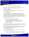
1.1.1
System 1
This is the simplest system consisting of a detector and a converter. This system can be
implemented for monitoring humidity in a production process such as food production.
No piping is required for the reference gas (air) which is fed in at the installation site.
The handy ZO21S standard gas unit is used for calibration.
Zero gas from this unit and span gas (air) is sent to the detector through a tube which is
connected during calibration.
CAUTION
• A needle (stop) valve should be connected to the calibration gas inlet of the detector.
The valve should be fully closed unless calibration is in progress.
• As this system uses ambient air for the reference gas, measuring accuracy will be
affected by the installation location.
Separate type Zirconia
High Temperature Humidity Analyzer,
Model ZR22G Detector
Model ZR402G Converter
EXA ZR402G
Stop valve
Signal
(6-core shield cable)
Heater (2-core)
, 100 to 240 V AC
Contact input
Analog outout, contact output
Digital output (HART)
Model ZO21S Standard gas unit
Calibration gas
,
F1.1E.EPS
Figure 1.1
1-2
IM 11M12A01-03E
1. Overview
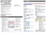
1.1.2
System 2
This system is for accurate monitoring and controlling humidity when the installation
environment is polluted with gases other than the air. Instrument air (clean and dry air
of oxygen concentration 21%) is used for the reference gas and the span gas for calibration. Zero gas is fed in from a cylinder during calibration. The gas flow is controlled by
the ZA8F flow setting unit (for manual valve operation).
Separate type Zirconia
High Temperature Humidity Analyzer,
Model ZR22G Detector
Model ZR402G Converter
EXA ZR402G
Check valve
or Stop valve
Signal
(6-core shield cable)
Heater (2-core)
Reference
gas
Calibration gas
Model ZA8F flow setting unit
Needle
Flowmeter
valve
, 100 to 240 V AC
Contact input
Analog outout, contact output
Digital output (HART)
Air Set
Instrument air
Span gas (Same as Zero gas
calibration unit)
Calibration gas pressure regulator
Calibration gas
unit case
Zero gas cylinder
F1.2E.EPS
Figure1.2
IM 11M12A01-03E
1-3
1.1.3
System 3
This system is for accurate monitoring and controlling of humidity. Instrument air
(clean and dry air) is used for the reference gas and the span gas for calibration. Zero
gas is fed in from a cylinder during calibration. The calibration gas flow is controlled
automatically by the ZR40H automatic calibration unit.
This system is similar to system 2, except that the calibration gas flow is automated
using the ZR40H automatic calibration unit.
Separate type Zirconia
High Temperature Humidity Analyzer,
Model ZR22G Detector
*2
Model ZR402G Converter
EXA ZR402G
*1
Signal
(6-core shield cable)
Check valve
,
Heater (2-core shield cable)
Reference gas
FlowmeterNeedle
vaive
100 to 240 V AC
Contact input
Analog output, contact output
Digital output (HART)
Air Set
Calibration gas
lnstrument air
Calibration gas pressure regulator
Model ZR40H Auto-Calibration unit
*3
Calibration gas
unit case
Zero gas cylinder
F1.3E.EPS
Figure1.3
*1 Shield cable : Use shielded signal cables, and connect the shield to the FG terminal
of the converter.
*2 Select the desired probe from the Probe Configuration table on page 1-5
*3 100% N2 gas cannot be used as the zero gas. Use approximately 1% of O2 gas (N2based).
1-4
IM 11M12A01-03E
1. Overview
1.2
< EXAxtZR > System Components
1.2.1
System Components
Model or Part No.
ZR22G
ZR402G
Product Name
Detector, Separate-type High-temperature
Humidity Analyzer, Detector
Converter, Separate-type High-temperature
Humidity Analyzer, Converter
Dust protector
Standard gas unit
Flow setting unit (for manual calibration)
Automatic calibration unit (for separate type)
Stop valve
Check valve
Air set
Separate type
System 1 System 2 System 3
ZH21B
ZO21S
ZA8F
ZR40H
L9852CB/G7016XH
K9292DN/K9292DS
K9473XH/K9473XJ,
G7004XF/K9473XG
G7001ZC
Zero gas cylinder
G7013XF/G7014XF
Pressure regulator for gas cylinder
E7044KF
Case assembly for calibration-gas cylinder
ZR22A
Heater Assembly
(Spare parts for Model ZR22G)
d
d
d
d
d
d
s
d
s
s
d
d
s
d
d
d
d
d
d
d
d
s
s
T1.1E.EPS
d : The essential products for the system
s : Selected depending on your applications
(d) : Select either
1.2.2
d
(d)
(d)
d
Detectors and Accessories
dGeneral-use Detector (sample gas temperature: 0 to 7008C)
Standard detector
Model
ZR22G
Mounting angle
The probe insertion length: 0.4 to 2m
Vertical to horizontal
The probe insertion length: 2.5 to 3m
Vertical
Detector with dust protector
Model
ZR22G-040
and
ZH21B
Mounting angle
Vertical to horizontal
(The probe insertion length: 0.4m)
F1.4E.EPS
IM 11M12A01-03E
1-5
2. Specifications
2.
Specifications
This chapter describes the specifications for the following:
ZR22G
General-use separate-type detector (See Section 2.2.1)
ZH21B
Dust protector
ZR402G
Separate-type converter
ZA8F
Flow setting unit (See Section 2.4.1)
ZR40H
Automatic calibration unit (See Section 2.4.2)
ZO21S
Standard gas unit (See Section 2.5)
2.1
General Specifications
2.1.1
Standard Specifications
(See Section 2.2.2)
(See Section 2.3)
High Temperature Humidity Analyzer
Oxygen concentration in mixed gas which consists of water vapor and air is proportional
to the volume rate of air, so the volume rate of water vapor can be calculated by the
oxygen concentration.
Measured Object:Water vapor (in vol%) in mixed gases (air and water vapor)
Measured System: Zirconia system
Measured Range: 0.01 to 100 vol% O2, 0 to 100 vol% H2O or 0 to 1.000 kg/kg
Output Signal: 4 to 20 mA DC (maximum load resistance 550V) Oxygen concentration;
Any setting in the range of 0 to 5 through 0 to 100 vol%O2 (in 1
vol% O2), or partial range.
Moisture quantity: 0 to 25 through 0 to 100 vol% H2O (in 1 vol% H2O), or partial
range.
Mixture ratio 0 to 0.2 through 0 to 1.000 kg/kg (in 0.001 kg/kg), or
partial range.
Digital Communication (HART): 250 to 550V, depending on quantity of field devices
connected to the loop (multi-drop mode).
(Note) HART is a registered trademark of the HART Communication
Foundation.
Display Range: Oxygen concentration; 0 to100 vol% O2 , Moisture quantity; 0 to 100
vol% H2O
Mixture ratio; 0 to 1 kg/kg
Relative humidity; 0 to 100 %RH
Dew point; -40 to 3708 C
(Note) Those values are calculated by temperature and absolute
pressure. Then accurate temperature and pressure value must be
input to the converter.
Warm-up Time: Approx. 20 min.
(Note) These characteristics are calculated by oxygen concentration
measured in air which include water vapor.
IM 11M12A01-03E
2-1
Repeatability: (Note1)
61 vol% H2O (sample gas pressure 2 kPa or less)
Linearity:
(Excluding standard gas tolerance)
(Note1)
(Use oxygen of known concentration (in the measuring range) as the
zero and span calibration gas.)
62 vol% H2O; (Sample gas pressure: within 60.49 kPa)
63 vol% H2O; (Sample gas pressure: 2 kPa or less)
Drift:
(Excluding the first two weeks in use)
(Note1)
both zero and span 63 vol% H2O/month
Response Time: Response of 90 % within 5 seconds. (Measured after gas is introduced
from calibration-gas inlet and analog output starts changing.)
(Note1) These tolerances do not apply to the pressure compensated
version, or where natural convection is used for the reference air.
2-2
IM 11M12A01-03E
2. Specifications
2.2
General-use Separate-type Detector and Related
Equipment
The “Detector with dust protector” consists of ZR22G general-use separate-type detector
and ZH21B dust protector (refer to Section 2.2.2).
2.2.1
ZR22G General-use Separate-type Detector
Sample Gas Temperature: 0 to 7008 C (Probe only)
It is necessary to mount the cell using Inconel cell-bolts when the
temperature is 6008 C or greater.
Sample Gas Pressure: -5 to +20 kPa (When the pressure in the process exceeds 3kPa,
it is recommended that you compensate the pressure. When the pressure
in the process exceeds 5kPa, you must perform pressure compensation.)
No pressure fluctuation in the process should be allowed.
Probe Length: 0.4, 0.7, 1.0, 1.5, 2.0, 2.5, 3.0 m
Probe Material: SUS 316 (JIS)
Ambient Temperature: -20 to +1508 C
Reference Air System: Natural Convection, Instrument Air
Instrument Air System (excluding Natural Convection):
Pressure; 200 kPa + the pressure inside the dryer, (It is recommended to
use air which has been dehumidified by cooling to dew point -208 C or
less, and with dust or oil mist removed.)
Consumption; Approx. 1Nl/min
Note: When the detector is used in conjunction with a check valve and a
ZA8F Flow Setting Unit, the maximum pressure of sample gas is 150
kPa. When with a check valve and a ZR40H Auto Calibration Unit, it is
200 kPa. If the pressure of your sample gas exceeds these limits, consult
with Yokogawa.
Material in Contact with Gas: SUS 316 (JIS), Zirconia, SUS 304 (JIS) (flange),
Hastelloy B, (Inconel 600, 601)
Construction: Heater and thermocouple replaceable construction. Non explosion-proof
JIS C0920 / equivalent to IP44D. Equivalent to NEMA 4X / IP66
(Achieved when the cable entry is completely sealed with a cable
gland in the recirculation pressure compensated version.)
Terminal Box Case: Material; Aluminium alloy
Terminal Box Paint Color:
Case; Mint green (Munsell 5.6BG3.3/2.9)
Cover; Mint green (Munsell 5.6BG3.3/2.9)
Finish: Polyurethane corrosion-resistant coating
Gas Connection: Rc 1/4 or 1/4 FNPT
Wiring Connection: G1/2, Pg13.5, M20 by 1.5mm, 1/2 NPT
Installation: Flange mounting
IM 11M12A01-03E
2-3
Probe Mounting Angle: Horizontal to vertically downward.
When the probe insertion length is 2 m or less, installing at angles from
horizontal to vertically downward is available.
When the probe insertion length exceeds 2.5 m, mount vertically downward (within 658 ) and use a probe protector.
Weight:
Insertion length of 0.4 m: approx. 6 kg (JIS 5K 65) / approx. 11 kg (ANSI 150 4)
Insertion length of 1.0 m: approx. 8 kg (JIS 5K 65) / approx. 13 kg (ANSI 150 4)
Insertion length of 1.5 m: approx. 10 kg (JIS 5K 65) / approx. 15 kg (ANSI 150 4)
Insertion length of 2.0 m: approx. 12 kg (JIS 5K 65) / approx. 17 kg (ANSI 150 4)
Insertion length of 3.0 m:
2-4
approx. 15 kg (JIS 5K 65) / approx. 20 kg (ANSI 150 4)
IM 11M12A01-03E
2. Specifications
Model and Codes
Model
[ Style : S2 ]
Suffix code
Option
code
Description
Separate type Detector of Zirconia High Temperature Humidity
Analyzer
0.4 m
Length -040
0.7 m
-070
1.0 m
-100
1.5 m
-150
2.0 m
-200
2.5 m
(*1)
-250
3.0 m
(*1)
-300
SUS316
Wetted material -S
Stainless steel with lnconel calibration gas tube
-C
ANSI Class 150 2 RF SUS304
-A
Flange
ANSI Class 150 3 RF SUS304
-B
(*2)
ANSI Class 150 4 RF SUS304
-C
DIN PN10 DN50 SUS304
-E
DIN PN10 DN80 SUS304
-F
DIN PN10 DN100 SUS304
-G
JIS 5K 65 FF SUS304
-K
JIS 10K 65 FF SUS304
-L
JIS 10K 80 FF SUS304
-M
JIS 10K 100 FF SUS304
-P
JPI Class 150 4 RF SUS304
-R
JPI Class 150 3 RF SUS304
-S
Westinghouse
-W
Reference air
-C
Natural convection
-E
External connection (Instrument air) (*8)
-P
Pressure Compensation (*8)
Gas Thread
-R
Rc 1/4
-T
1/4 NPT(F)
-P
Connection box thred
G1/2
-G
Pg13.5
-M
M20 x1.5 mm
-T
1/2NPT
-Q
Quick connect (*6)
-J
Instruction manual
Japanese
-E
English
-A
Always-A
Options
/D
DERAKANE coating (*7)
/C
Inconel bolt
(*3)
/CV
Check valve
(*4)
/SV
Stop valve
(*4)
/SCT
Stainless steel tag plate
(*5)
/PT
Printed tag plate
(*5)
*1 When installing horizontally the probe whose insertion length is 2.5 meters or more, use the Probe Protector. Be sure to specify
T2.1E.EPS
ZO21R-L-hhh-h. Specify the flange suffix code either -C or -K.
*2 The thickness of the flange depends on its dimensions.
*3 Inconel probe bolts and U shape pipe for calibration are used. Use this option for high temperature use (ranging from 600 to 700 8C).
*4 Specify either /CV or /SV option code.
*5 Specify either /SCT or /PT option code.
*6 Not waterproof, protect from rain.Operating maximum temperature is 80 8C. Available only in the U.S.
*7 Available only in the U.S. DERAKANE is a registered trademark of the Dow Chemical Company.
*8 Piping for reference air must be installed to supply reference air constantly at a specified flow rate.
ZR22G
IM 11M12A01-03E
2-5
EXTERNAL DIMENSIONS
Model ZR22G Detectors Separate type Zirconia High Temperature Humidity Analyzer
L
283 to 292
85
[124
[50.8
t
L=0.15, 0.4, 0.7, 1.0,
1.5, 2.0, 2.5, 3.0 (m)
Rc1/4 or 1/4NPT
Reference air inlet
155 to 163
69
C
2-G1/2,2-1/2NPT etc.
Cable connection port
48
25
[A
[B
Rc1/4 or 1/4NPT
Calibration gas inlet
Flange
Flange
ANSI Class 150 2 RF SUS304
ANSI Class 150 3 RF SUS304
ANSI Class 150 4 RF SUS304
DIN PN10 DN50 SUS304
DIN PN10 DN80 SUS304
DIN PN10 DN100 SUS304
JIS 5K 65 FF SUS304
JIS 10K 65 FF SUS304
JIS 10K 80 FF SUS304
JIS 10K 100 FF SUS304
JIS 5K 32 FF SUS304
JPI Class 150 4 RF SUS304
JPI Class 150 3 RF SUS304
Westinghouse
2-6
A
152.4
190.5
228.6
165
200
220
155
175
185
210
115
229
190
155
B
120.6
152.4
190.5
125
160
180
130
140
150
175
90
190.5
152.4
127
C
4 - [19
4 - [19
8 - [19
4 - [18
8 - [18
8 - [18
4 - [15
4 - [19
8 - [19
8 - [19
4 - [15
8 - [19
4 - [19
4 - [11.5
t
19
24
24
18
20
20
14
18
18
18
5
24
24
14
Flange
C
[A
[B
Flange
F07_01.EPS
IM 11M12A01-03E
2. Specifications
Model ZR22G...-P Detectors(with pressure compensation), Separate type Zirconia High Temperature
Humidity Analyzer, Detectors
303
L
85
f124
f50.8
t
L=0.15, 0.4, 0.7, 1.0,
1.5, 2.0, 2.5, 3.0 (m)
Rc1/4 or 1/4NPT
Reference air inlet
L
156
87
C
2-G1/2, 2-1/2NPT etc.
Cable connection port
t
48
25
[A
[B
Reference gas outlet
Flange
PIPING
:B
PIPING : A
Flange
ANSI Class 150 2 RF SUS304
ANSI Class 150 3 RF SUS304
ANSI Class 150 4 RF SUS304
DIN PN10 DN50 SUS304
DIN PN10 DN80 SUS304
DIN PN10 DN100 SUS304
JIS 5K 65 FF SUS304
JIS 10K 65 FF SUS304
JIS 10K 80 FF SUS304
JIS 10K 100 FF SUS304
JPI Class 150 4 RF SUS304
JPI Class 150 3 RF SUS304
Westinghouse
IM 11M12A01-03E
A
152.4
190.5
228.6
165
200
220
155
175
185
210
229
190
155
B
120.6
152.4
190.5
125
160
180
130
140
150
175
190.5
152.4
127
Rc1/4 or 1/4NPT
Calibration gas inlet
Stop Valve
C
4 - [19
4 - [19
8 - [19
4 - [18
8 - [18
8 - [18
4 - [15
4 - [19
8 - [19
8 - [19
8 - [19
4 - [19
4 - [11.5
Flange
C
t
19
24
24
18
20
20
14
18
18
18
24
24
14
PIPING
A
B
B
A
B
B
A
A
B
B
B
B
A
[A
[B
Flange
F07_02.EPS
2-7
2.2.2
ZH21B Dust Protector
This protector is designed to protect the probe output from dust agitation (i.e., to prevent
combustible materials from entering the probe cell where humidity measurements are
made) in a dusty environment.
d Standard Specification
Insertion length: 0.428m
Flange:
JIS 5K 80 FF SUS304 or ANSI Class 150 4 FF SUS304 (However,
flange thickness is different)
Material:
SUS 316(JIS), SUS 304(JIS) (flange)
Weight:
Approximately 6kg (JIS), approximately 8.5kg (ANSI)
Mounting:
Mounted on the probe or process flange with bolts and associated
nuts and washers.
Model
Suffix code Option
code
Description
Dust Protector (0 to 600 8C)
ZH21B
Insertion
-040
0.428 m
length
-J
Flange ( *1)
JIS 5K 80 FF SUS304 (1)
-A
Style code
ANSI Class 150 4B FF SUS304 (2)
Style B
*B
* The flange thickness varies.
T2.2E.EPS
Specify the probe ZR22G-040-h-K in code of (1)
ZR22G-040-h-C in code of (2)
Dust protector
Unit ; mm
428
[72
[76.3
t
[A
D
Install facing upwards
C
C
[B
[B
Insertion hole;minimum[80
Insertion hole;minimum[80
JIS flange
ANSI flange
F2.3E.EPS
Size of each part of flange
Flange
JIS 5K 80 FF
SUS304
ANSI Class
150 4B FF SUS304
A
B
180
145
228.6
190.5
C
four holes of
diameter 19
t
D
12
40
12
50
eight holes of
diameter 19
2.3E-1.EPS
2-8
IM 11M12A01-03E
2. Specifications
2.3
ZR402G Separate-type Converter
2.3.1
Standard Specifications
Operated using an LCD touchscreen on the converter.
Display: LCD display of size 320 by 240 dot with touchscreen.
Output Signal: 4 to 20 mA DC, two points (maximum load resistance 550 V)
Contact Output Signal: four points (one is fail-safe, normally open)
Contact Input: two points
Analog Input: one point (thermal input 4-20 mA)
Auto-calibration Output: Two points (for dedicated auto-calibration unit)
Ambient Temperature: -20 to +558C
Storage Temperature: -30 to +708C
Humidity Ambient: 0 to 95%RH (Non-condensing)
Installation Altitude: 2000 m or less
Category based on IEC 1010: II (Note)
Pollution degree based on IEC 1010: 2 (Note)
Note: Installation category, called over-voltage category, specifies impulse withstanding voltage. Category II is for electrical equipment.
Pollution degree indicates the degree of existence of solid, liquid, gas or other
inclusions which may reduce breakdown voltage. Degree 2 is the normal indoor
environment.
Power Supply Voltage: Ratings; 100 to 240 V AC
Acceptable range; 85 to 264 V AC
Power Supply Frequency:
Ratings; 50/60 Hz Acceptable range; 45 to 66 Hz
Power Consumption: Max. 300 W, approx. 100 W for ordinary use.
Safety and EMC conforming standards
Safety: EN61010-1
CSA C22.2 No.61010-1
UL61010-1
EMC: EN 61326 Class A
EN 55011 Class A Group 1
EN 61000-3-2
AS/NZS CISPR 11
Maximum Distance between Probe and Converter: Conductor two-way resistance must
be 10 V or less (when a 1.25 mm2 cable or equivalent is used, 300 m or less.)
Construction: Outdoor installation, equivalent to NEMA 4 (with conduit holes
completely sealed with a plastic cable gland optional)
Wiring Connection: G1/2, Pg13.5, M20 by 1.5 mm, 1/2 NPT, eight holes
Installation: Panel, wall or 2B pipe mounting
Case: Aluminum alloy
Paint Color: Door: Sliver gray (Munsell 3.2PB7.4/1.2)
Case: Sliver gray (Munsell 3.2PB7.4/1.2)
Finish: Polyurethane corrosion-resistant coating
Weight: Approx. 6 kg
IM 11M12A01-03E
2-9
2.3.2
Function
Display Functions:
Value Display;
Displays values of the measured Oxygen concentration,
moisture quantity, mixture ratio etc.
Graph Display;
Displays trends of measured oxygen concentration moisture
quantity, mixture ratio etc.
Data Display;Displays various useful data for maintenance, such as cell
temperature, reference junction temperature, maximum/
minimum moisture quantity and the like.
Status Messages;
Indicates an alarm or error occurrence with flashing of the corresponding icon. Indicates status such as warming-up, calibrating,
or the like by symbols.
Alarm, Error Display: Displays alarms such as “Abnormal moisture quantity” or
errors such as “Abnormal cell e.m.f.” when any such status
occurs.
Calibration Functions:
Auto-Calibration;
Requires the Auto-calibration Unit. It calibrates automatically at
specified intervals.
Semi-auto Calibration; Requires the Auto-calibration Unit. Input calibration direction
on the touchpanel or contact, then it calibrates automatically
afterwards.
Manual Calibration; Calibration with opening/closing the valve of calibration gas in
operation interactively with an LCD panel.
Blowback Function:
Output through the contact at a set period and time. Auto/semi-auto
selectable.
Maintenance Functions:
Can update data settings during daily operation and checking.
Display data settings, calibration data settings, blowback data settings,
current output loop check, input/output contact check.
Setup Functions:
Initial settings suit for the plant conditions when installing the con
verter. Equipment settings, current output data settings, alarm data
settings, contact data settings, other settings.
Self-diagnosis:
This function diagnoses conditions of the converter or the probe and
indicates when any abnormal condition occurs.
Password Functions:
Enter your password to operate the analyzer excepting data display.
Individual passwords can be set for maintenance and setup.
2-10
IM 11M12A01-03E
2. Specifications
Display and setting content:
Measuring-related items: Oxygen concentration (vol% O2), moisture quantity(vol% H2O),
mixture ratio (kg/kg), relative humidity (%RH) and dew point (8 C)
Display Related Items: Oxygen concentration (vol% O2), Moisture quantity (vol% H2O),
mixture ratio (kg/kg), relative humidity (%RH), dew point (8 C), cell temperature (8 C), thermocouple reference junction temperature (8 C), maximum/
minimum/average oxygen concentration (vol% O2), maxi-mum/minimum/
average moisture quantity (vol% H2O), maximum/minimum/average mixture
ratio (kg/kg), cell e.m.f. (mV), output 1, 2 current (mA), cell response time
(seconds), cell internal resistance (V), cell condition (in four grades), heater ontime ratio (%), calibration history (ten times), time (year/month/day/hour/
minute)
Calibration Setting Items: Span gas concentration (vol% O2), zero gas concentration
(vol% O2), calibration mode (auto, semi-auto, manual), calibration type and
method (zero-span calibration, zero calibration only, span calibration only),
stabilization time (min.sec), calibration time (min.sec), calibration period (day/
hour), starting time (year/month/day/hour/minute)
Output Related Items: Analog output/output mode selection, value conditions when
warming-up/maintenance/calibrating(or blowback)/abnormal, oxygen concentration at 4mA/20mA (vol% O2), moisture quantity at 4mA/20mA (vol% H2O),
mixture ratio at 4mA/20mA (kg/kg), time constant.
Alarm Related Items: Oxygen concentration high-alarm/high-high alarm limit values
(vol% O2), Oxygen concentration low-alarm/low-low alarm limit values (vol%
O2), moisture quantity high-alarm/high-high alarm limit values (vol% H2O),
moisture quantity low-alarm/low-low alarm limit values (vol% H2O), mixture
ratio high-alarm/high-high alarm limit value (kg/kg), mixture ratio low-alarm/
low-low alarm limit values (kg/kg), oxygen concentration alarm hysteresis
(vol% O2), moisture quantity alarm hysteresis (vol% H2O), mixture ratio alarm
hysteresis (kg/kg), oxygen concentration/moisture quantity/mixture ratio alarm
detection, alarm delay (seconds).
Contact Related Items: Selection of contact input 1 and 2, selection of contact output 1
to 3 (abnormal, high-high alarm, high-alarm, low-alarm, low-low alarm,
maintenance, calibrating, range switching, warming-up, calibration-gas pressure-decrease, temperature high-alarm, blow back, unburnt gas detected)
Converter Output: Two points mA analog output (4 to 20 mA DC (maximum load
resistance of 550V) and one of two mA digital output points (HART) (minimum load resistance of 250V).
Range: any setting between 0 to 5 through 0 to 100 vol% O2, 0 to 25 through 0 to 100
vol% H2O, 0 to 0.200 through 0 to 1.000 kg/kg or partial range is available.
For the log output, the minimum range values are fixed at 0.1 vol% O2 for the
oxygen concentration, 0.1 vol% H2O for the moisture quantity, and 0.01 kg/kg
for the mixture ratio.
4 to 20 mA DC linear or log can be selected.
Input/output isolation provided.
Output damping 0-255 (sec.)
Can select hold or non-hold, and set preset value for hold.
IM 11M12A01-03E
2-11
Contact Output: Four points, contact capacity 30V DC 3A, 250V AC 3A
(resistive load).
Three of the output points can be selected to either normally energized or
normally de-energized status.
Delayed functions (0 to 255 seconds) and hysteresis function (0 to 9.9 vol% O2
can be added to high/low-alarms.
The following functions are programmable for contact outputs.
(1) Abnormal, (2) High-high alarm, (3) High-alarm, (4) Low-low alarm, (5)
Low-alarm, (6) Maintenance, (7) Calibration, (8) Range switching answer-back,
(9) Warm-up, (10) Calibration-gas pressure decrease (answerback of contact
input), (11) Temperature high-alarm, (12) Blowback start, (13) Flameout gas
detection (answerback of contact input), (14) Calibration coefficient alarm, (15)
Startup power stabilization timeout alarm
Contact output 4 is set to normally operated, and fixed error status.
Converter Input: Thermal input one point (4 to 20 mA DC)
Contact Input: Two points, voltage-free contact inputs
The following functions are programmable for contact inputs:
(1) Calibration-gas pressure decrease alarm, (2) Range switching (switched
range is fixed), (3) External calibration start, (4) Process alarm (if this signal is
received, the heater power turns off), (5) Blowback start
Contact capacity: Off-state leakage current: 3 mA or less
Self-diagnosis: cell abnormal , cell temperature abnormal (low/high), calibration
abnormal, A/D converter defective, digital circuit defective
Calibration:Method; zero/span calibration
Calibration mode; automatic, semi-automatic and manual (All are operated
interactively with an LCD touchpanel). Either zero or span can be skipped.
Zero calibration-gas concentration setting range: 0.3 to 100 vol% O2 (minimum
in 0.01 vol%).
Span calibration-gas concentration setting range: 4.5 to 100 vol% O2 (minimum
in 0.01 vol%).
Use nitrogen-based mixed gas containing about 10% of oxygen for standard
zero-gas, and 80 to 100 % of oxygen for standard span-gas.
Calibration period; date/time setting: maximum 255 days
2-12
IM 11M12A01-03E
2. Specifications
d Model and Suffix Codes
Model
Suffix code
Option
code
Description
Separate type Zirconia High Temperature
Humidity Analyzer, Converter
ZR402G
-P
-G
-M
-T
Display
-J
-E
-G
-F
Instruction manual -J
-E
G1/2
Pg13.5
M20x1.5 mm
1/2NPT
Japanese
English
German
French
Converter
thread
Japanese
English
Always -A
-A
Options
Tag plates
/HS
/H
/SCT
Set for Humidity Analyzer (*3)
/PT
Printed tag plate
Hood (*2)
Stainless steel tag plate (*1)
*1 Specify either /SCT or /PT option code.
*2 Sun shield hood is still effective even if scratched.
*3 Be sure to use the equipment with the option code /HS.
IM 11M12A01-03E
(*1)
T2.4E.EPS
2-13
d External Dimensions
Unit ;mm
1 to 6 (Panel Thickness)
2-inch mounting pipe
4 - f 6 holes
for Wall mounting
120.2
8
10
57.3
228
36
54.7
136.3
(1/2NPT)
100
126.5
280
EXA ZR402G
111
40
40
40
46 23
8-G1/2, 8-1/2NPT etc
(Wiring connection)
38 24 14 38
( for wall mounting)
126.5
274
+2
0
4 - f 6 holes
4-R8 to R10
or
4-C5 to C8
+2
0
190
183
Wall mounting
Panel Cut-out
F2.5E.EPS
d Accessories
2-14
Item
Fuse
Bracket for mounting
Part. No.
A1113EF
F9554AL
Qty
1
1
Screw for Bracket
F9123GF
1
Description
3.15A
for pipe mounting, panel mounting
or wall mounting
IM 11M12A01-03E
2. Specifications
d Hood (Option / H)
243
62
123
64
205.5
63
64
155.5
63
39 62
55
Unit ;mm
94.5
251.5
64
63
ZR402G
Hood material : Aluminum
IM 11M12A01-03E
2-15
2.4
ZA8F Flow Setting Unit and ZR40H Automatic Calibration Unit
2.4.1
ZA8F Flow Setting Unit
This flow setting unit is applied to the reference gas and the calibration gas in a system
configuration (System 2).
This unit consists of a flow meter and flow control valves to control the flow of calibration gas and reference air.
• Standard Specifications
FIowmeter: Calibration gas; 0.1 to 1.0 l/min. Reference air; 0.1 to 1.0 l/min.
Construction: Dust-proof and rainproof construction
Case Material: SPCC (Cold rolled steel sheet)
Painting: Baked epoxy resin, Dark-green (Munsell 2.0 GY 3.1/0.5 or equivalent)
Pipe Connections: Rc1/4 or 1/4FNPT
Reference Air pressure: Clean air supply of measured gas pressure plus approx. 50 kPa G
(or measured gas pressure plus approx. 150kPa G when a check valve is used)
pressure at inlet of the auto-calibration unit (Maximum 300 kPaG).
Air Consumption: Approx. 1.5 l/min
Weight: Approx. 2kg
Calibration gas (zero gas,span gas) flow : 0.7 l/min (at calibration time only)
d Model and Codes
Model
Suffix code
ZA8F
Joint
Style code
Option code
Description
Flow setting unit
-J
-A
*B
Rc 1/4
With 1/4" NPT adapter
Style A
T2.5E.EPS
2-16
IM 11M12A01-03E
2. Specifications
d External Dimensions
Unit: mm
f6 hole
180
7
140
REFERENCE
CHECK
ZERO
SRAN
Zero gas outlet Span gas inlet
Zero gas inlet
26
Reference air outlet
222.8
235.8
REFERENCE
20
35
35
35
35
20
8
35
70
4-Rc1/4
Piping connection
port
Instrument air inlet
CHECK
OUT
Flow
meter
ZERO
GAS IN
SPAN
GAS IN
REF
OUT
Flow
meter
AIR IN
Instrument air
Approx 1.5 l/min.
Airset
Air pressure:
without check valve ; measured gas pressure 1 approx.50 kPaG
with check valve ; measured gas pressure 1 approx.150 kPaG
F2.6E.EPS
IM 11M12A01-03E
2-17
2.4.2
ZR40H Automatic Calibration Unit
This automatic calibration unit is applied to supply specified flow of reference gas and
calibration gas during automatic calibration to the detector in a system configuration
(System 3).
• Specifications
Used when auto calibration is required for the separate type and instrument air is
provided. The solenoid valves are provided as standard.
Construction: Dust-proof and rainproof construction:
NEMA4X/IP67 solenoid valve only (excluding flowmeter)
Mounting: 2-inch pipe or wall mounting, no vibration
Materials: Body; Aluminum alloy, Piping; SUS316 (JIS), SUS304 (JIS), Flowmeter; MA
(acrylic resin), Bracket ; sus304 (JIS)
Finish: Polyurethane corrosion-resistance coating, mint green (Munse11 5.6BG3.3/2.9)
Piping Connection: Refer to Model and Suffix Codes
Power Supply: 24V DC (from ZR402G), Power consumption; Approx. 1.3W
Reference Air Pressure: Sample gas pressure plus Approx. 150 kPa (690 kPa max.),
(Pressure at inlet of auto-calibration unit)
Air Consumption: Approx. 1.5 l/min
Weight: Approx. 3.5 kg
Ambient Temperature: -20 to +558 C, no condensation or freezing
Ambient Humidity: 0 to 95% RH
Storage Temperature: -30 to +658 C
d Model and Codes
Model
Suffix code
Option code
ZR40H
Gas piping connection
Wiring connection
Automatic calibration unit for ZR402G
-R
Rc 1/4
-T
1/4" NPT
-P
Pipe connection (G1/2)
-G
Pg 13.5
-M
20 mm (M20 x 1.5)
1/2 NPT
-T
-
Description
-A
Always -A
T2.5-1E.EPS
2-18
IM 11M12A01-03E
2. Specifications
d External Dimensions
Unit : mm
wiring inlet ; 2-G1/2,Pg13.5,M2031.5 or 1/2NPT(Female)
2B pipe mounting example
(wiring inlet is at same position on rear)
*1 with four M6 screws can wall-mount
90
26
116.5
54
71.5
*1
41.2
4-
f
140
6.5
12
41.2
49.5
Flowmeter
223
250
OCK
Setting Valve for
reference air
Setting Valve for
calibration gas
Zero gas air inlet
Rc1/4 or 1/4 NPT(Female)
Rc1/4 or 1/4 NPT(Female)
26
42
46
102
16
58
MAX
calibration gas outlet
40
reference air outlet
Rc1/4 or 1/4 NPT(Female)
30
47.5
25
reference gas inlet
Rc1/4 or 1/4 NPT(Female)
F2.6-2E.EPS
IM 11M12A01-03E
2-19
Piping
REF
OUT
CHECK
OUT
EV1
ZERO GAS IN
flow
meter
flow
meter
*2
*2
EV2
AIR IN
Instrument air Approx.
1.5 l/min.
*2 Needle valve is supplied as accessory with flow meter.
F2.6-3E.EPS
2-20
IM 11M12A01-03E
2. Specifications
2.5
ZO21S Standard Gas Unit
This is a handy unit to supply zero gas and span gas to the detector in a system configuration based on System 1. It is used in combination with the detector only during
calibration.
d Standard Specifications
Function: Portable unit for calibration gas supply consisting of span gas (air) pump, zero
gas cylinder with sealed inlet, flow rate checker and flow rate needle valve.
Sealed Zero Gas Cylinders (6 provided): E7050BA
Capacity: 1 l
Filled pressure: Approx. 686 kPa G (at 35 8 C)
Composition: 0.95 to 1.0 vo1% O2+N2 based
Power Supply: l00, 110, 115, 200, 220, 240 V AC6 10%, 50/60 Hz
Power Consumption: Max. 5 VA
Case Material: SPCC (Cold rolled steel sheet)
Point: Epoxy resin, baked
Paint Color:
Mainframe; Munsell 2.0 GY3.1/0.5 equivalent
Cover; Munsell 2.8 GY6.4/0.9 equivalent
Piping: f 63f 4mm flexible tube connection
Span Gas: Internal pump draws in air from atmosphere, and feeds to detector.
Weight: Approx. 3 kg
p Non CE Mark.
d Model and Codes
Model
Suffix code
Power
supply
Panel
Style code
Option code
Description
Standard gas unit
ZO21S
-2
-3
-4
-5
-7
-8
200 V AC 50/60 Hz
220 V AC 50/60 Hz
240 V AC 50/60 Hz
100 V AC 50/60 Hz
110 V AC 50/60 Hz
115 V AC 50/60 Hz
Japanese version
English version
-J
-E
*A
Style A
T2.6E.EPS
IM 11M12A01-03E
2-21
d External Dimensions
253
228
92
Unit : mm
Flow checker
Span gas valve
Zero gas valve
1600
Gas outlet
354
Zero gas cyilnder (6 cyilnder): E7050BA
F2.7E.EPS
2.6
Other Equipment
2.6.1
Stop Valve (Part Number: L9852CB or G7016XH)
This valve is mounted on the calibration gas line in the system to allow for one-touch
calibration. This applies to the system configuration shown for system 1 in section 1.
Standard Specifications
Connection: Rc 1/4 or 1/4 FNPT
Material: SUS 316 (JIS)
Weight: Approx. 80 g
Description
Part No.
L9852CB
Joint: RC 1/4,
Material: SUS 316 (JIS)
G7016XH
Joint: 1/4 NPT, Material: SUS 316 (JIS)
T2.9E.EPS
Unit: mm
Rc1/4 or 1/4NPT
(Full open length)
55
43
40
F15.EPS
2-22
IM 11M12A01-03E
2. Specifications
2.6.2
Check Valve (Part Number: K9292DN or K9292DS)
This valve is mounted on the calibration gas line (directly connected to the detector).
This is applied to a system based on the (System 2 and 3) system configuration.
This valve prevents the process gas from entering the calibration gas line. Although it
functions as a stop valve, operation is easier than a stop valve as it does not require
opening/closing at each calibration.
Screw a check valve into the calibration gas inlet of the detector instead of the stop
valve.
Standard Specifications
Connection: Rc1/4 or 1/4FNPT
Material: SUS304 (JIS)
Pressure: 70 kPa G or more,and 350 kPa G or less
Weight: Approx. 40 g
Description
Part No.
K9292DN
Joint: RC 1/4, Material: SUS304 (JIS)
K9292DS
Joint: 1/4 NPT, Material: SUS304 (JIS)
T2.10E.EPS
K9292DN : Rc 1/4 (A part), R 1/4(B part)
Unit : mm
K9292DS : 1/4FNPT(A part),1/4NPT(Male)(B part)
A
B
Approx.19
Approx.54
F2.11E.EPS
IM 11M12A01-03E
2-23
2.6.3
Air Set
Part Number: K9473XH or K9473XJ
This set is used to lower the pressure when instrument air is used as the reference and
span gases.
Standard Specifications
Primary Pressure: Max. 2 MPa G
Secondary Pressure: 0 to 0.25 MPa G
Connection: Rc1/4 or 1/4FNPT (includes joint adapter)
Weight: Approx.1 kg
Description
Part No.
K9473XH
Joint: Rc 1/4, Material: Aluminum
K9473XJ
Joint: 1/4 NPT (F) , Material: Body; Aluminum, Adapter; Zinc alloy
T2.11E.EPS
Unit: mm
Dimensions in parentheses are approximate.
IN
(135.5)
OUT
(53.5)
(63)
[54
(43.5)
60
[48
40
69.5
(116)
7
28
18.5
42
8
Bracket Mounting Dimensions
K9473XH: Piping connection (IN: Primary side, OUT: Secondary side), Rc1/4
K9473XJ: Piping connection (IN: Primary side, OUT: Secondary side), 1/4NPT
2-24
IM 11M12A01-03E
2. Specifications
Part Number; G7004XF or K9473XG
Primary Pressure: Max. 1 MPa G
Secondary Pressure: 0.02 to 0.5 MPa G
Connection: Rc1/4 or 1/4 FNPT with joint adapter
Part No.
Description
G7004XF
Joint: Rc 1/4, Material: Zinc Alloy
K9473XG
Joint: 1/4 NPT (F) , Material: Body; Zinc Alloy, Adapter; SUS316
T2.13E.EPS
d External Dimensions
Unit : mm
View A
Panel cut dimensions
Horizontal
mounting
22
Vertical
mounting
[15
40
+0.5
2-2.2 -0
40
2-[6.5
max. 55
2-[6 screw depth 10
Secondary
pressure
gauge
Secondary
Panel (Vertical
mounting)
A
88
Primary
Max. 210
[74
Panel (Horizontal
mounting)
G7004XF: Rc 1/4
K9473XG: 1/4NPT connector
Approx. 122
IM 11M12A01-03E
2-25
2.6.4
Zero-gas Cylinder (Part Number: G7001ZC)
The gas from this cylinder is used as the calibration zero gas and detector purge gas.
Standard Specifications
Capacity: 3.4 l
Filled pressure: 9.8 to 12 MPa G
Composition: 0.95 to 1.0 vol% O2 in N2
(Note) Export of such high pressure filled gas cylinders to most countries is prohibited
or restricted.
325
485
Unit : mm
[140
2.6.5
Weight : Approx. 6 kg
F2213.EPS
Pressure Regulator for Gas Cylinder (Part Number: G7013XF or G7014XF)
This regulator valve is used with the zero gas cylinders.
Standard Specifications
Primary Pressure: Max. 14.8 MPa G
Secondary Pressure: 0 to 0.4 MPa G
Connection: Inlet W22 14 threads, right hand screw
Outlet Rc1/4 or 1/4FNPT
Material: Brass body
Approx.112
Primary
Secondary
pressure gauge pressure gauge
Unit : mm
Regulator handle
W22 (Righthanded screw)
ACH
IN
´J
HO
TAK
I
ACH
O
IH
TAK
Stop valve
J ´
p Outlet
Secondary
safety valve
Primary
safety valve
Approx. 59
Approx. 82
Approx. 163
2-26
Approx. 174
Part No.
p Outlet
G7013XF
Rc1/4
G7014XF
1/4 NPT female screw
IM 11M12A01-03E
2. Specifications
2.6.6
Case Assembly for Calibration-gas Cylinder (Part Number: E7044KF)
This case is used to store the zero gas cylinders.
Standard Specifications
Case Paint: Baked epoxy resin, Jade green (Munsell 7.5 BG 4/1.5)
Installation: 2B pipe mounting
Material: SPCC (Cold rolled steel sheet)
Weight: Approx. 3.6kg, 10 kg with gas cylinder
(Note) Export of such high pressure filled gas cylinders to most countries is prohibited
or restricted.
Unit : mm
324
Pressure regulator
G7013XF/
G7014XF
200
180
Zero gas cylinder
(G7001ZC)
496
(Note) E7044KF (case assembly) has no zero gas cylinder
and pressure regulator.
IM 11M12A01-03E
2B pipe ( f60.5)
F2.15E.EPS
2-27
2.6.7
Model ZR22A Heater Assembly
Table 2.1 ZR22A
Style: S2
Model
Suffix code
Length
(p1)
Description
Option code
Heater Assembly for ZR22G
ZR22A
0.15 m
0.4 m
0.7 m
1m
1.5 m
2m
2.5 m
3m
-015
-040
-070
-100
-150
-200
-250
-300
Jig for change
with Jig
None
-A
-N
Reference air (*3)
(*2)
-A
Reference air Natural convention
External connection (Instrument air)
-B
-C
Pressure compensated (for ZR22G S2)
Pressure compensated (for ZR22G S1)
p1 Suffix code of length should be selected as same as ZR22G installed.
p2 Jig part no. is K9470BX to order as a parts after purchase.
p3 Select appropriately among "-A", "-B", "-C" according to the reference air supply method and style.
(Note) The heater is made of ceramic, do not drop or subject it to pressure stress.
T23.EPS
Unit : mm
30
[ 45
(K9470BX)
K9470BX
Jig for change
[ 21.7
d External Dimensions
L612
L length
F2.16E.EPS
2-28
Model & Code
L
Weight (kg)
ZR22A-040
552
Approx. 0.8
ZR22A-070
852
Approx. 1.2
ZR22A-100
1152
Approx. 1.6
ZR22A-150
1652
Approx. 2.2
ZR22A-200
2152
Approx. 2.8
ZR22A-250
2652
Approx. 3.4
ZR22A-300
3152
Approx. 4.0
IM 11M12A01-03E
3. Installation
3.
Installation
This chapter describes installation of the following equipment:
3.1
Detector
3.2
Converter
3.3
ZA8F Flow Setting Unit
3.4
ZR40H Automatic Calibration Unit
3.5
E7044KF Case Assembly for Calibration-gas Cylinder
3.1
Installation of the Detector
3.1.1
Location
The following should be taken into consideration when installing the detector:
(1) Easy and safe access to the detector for checking and maintenance work.
(2) Ambient temperature of not more than 150°C, and the terminal box should not
affected by radiant heat.
(3) A clean environment without any corrosive gases.
CAUTION
• A natural convection type detector (model ZR22G-h-h-h-C), which uses ambient air
as reference gas, requires that the ambient oxygen concentration be constant.
(4) No vibration.
(5) The measurement gas satisfies the specifications described in Chapter 2.
(6) No measurement gas-pressure fluctuations.
IM 11M12A01-03E
3-1
3.1.2
Probe Insertion Hole
Includes those analyzers equipped with a dust protector.
When preparing the probe insertion hole, the following should be taken into consideration:
CAUTION
• The outside dimension of detector may vary depending on its options. Use a pipe that
is large enough for the detector. Refer to Figure 3.1 for the dimensions.
• If the detector is mounted horizontally, the calibration gas inlet and reference gas inlet
should face downwards.
When using the detector with pressure compensation, ensure that the flange gasket
does not block the reference air outlet on the detector flange. If the flange gasket
blocks the outlet, the detector cannot conduct pressure compensation. Where necessary, make a notch in the flange gasket. Confirm the external dimensions of the
detector in Section 3.7 before installation.
• The sensor (zirconia cell) at the probe tip may deteriorate due to condensation as it is
always at high temperature.
(1) Do not mount the probe with the tip higher than the probe base.
(2) If the probe length is 2.5 meters or more, the detector should be mounted vertically
(nomore than a 5° tilt).
(3) The detector probe should be mounted at right angles to the measurement gas
flow or the probe tip should point downstream.
Figure 3.1 illustrates an example of the probe insertion hole.
(vertical)
Bounds of the probe
insertion hole location
Flange matches
to the detector size
100mm
*1
Type
Standard
With dust protector
Outside diameter of detector
50.8 mm in diameter (Note)
80 mm in diameter or longer(Note)
(horizontal)
*1
*Note
100mm
Four-hole flange
(Note)
When using the detector with ZH21B dust protector the diameter of the hole
should be 80mm or larger.
Eight-hole flange
JIS flange(the detector
with dust protector)
F3.1E.EPS
When using the detector with pressure compensation, ensure that the flange gasket does
not block the reference air outlet on the detector flange. If the flange gasket blocks the
outlet, the detector cannot conduct pressure compensation. Where necessary, make a
notch in the flange gasket. Confirm the outside dimensions of the detector in Section 3.7
before installation.
Figure 3.1 Example of forming probe insertion hole
3-2
IM 11M12A01-03E
3. Installation
3.1.3
Installation of the Detector
CAUTION
• The cell (sensor) at the tip of the detector is made of ceramic (zirconia). Do not drop
the detector, as impact will damage it.
• A gasket should be used between the flanges to prevent gas leakage. The gasket
material should be heatproof and corrosion-proof, suited to the characteristics of the
measured gas
The following should be taken into consideration when mounting the general-use
detector:
<General-use detector>
(1) Make sure that the cell mounting screws (four) at the probe tip are not loose.
(2) Where the detector is mounted horizontally, the calibration gas inlet and the reference gas inlet should face downward.
3.1.4
Installation of ZH21B Dust Protector
(1) Put the gasket that is provided by the user between the flanges and mount the dust
protector in the probe insertion hole.
(2) Make sure that the cell assembly mounting screws (four) at the probe tip are not
loose.
(3) Mount the detector so that the calibration gas inlet and the reference gas inlet face
downward
Unit;mm
Calibration gas inlet
Reference gas inlet
F3.2E.EPS
Figure 3.2 Installation of the dust filter
IM 11M12A01-03E
3-3
3.2
3.2.1
Installation of the Converter
Location
The following should be taken into consideration when installing the converter:
(1) Readability of the indicated values of moisture concentration or messages on the
converter display.
Easy and safe access to the converter for operating keys on the panel.
(2) Easy and safe access to the converter for checking and maintenance work.
(3) An ambient temperature of not more than 558C and little change in temperature
(recommended within 158C in a day).
(4) The normal ambient humidity (recommended between 40 to 75 %RH) and without
any corrosive gases.
(5) No vibration.
(6) Near to the detector.
(7) Not in direct rays of the sun. If the sun shines on the converter, prepare the hood (/
H) or other appropriate sunshade.
3.2.2
Mounting of the Converter
The converter can be mounted on a pipe (nominal JIS 50A: O.D. 60.5 mm), a wall or a
panel. The converter can be mounted at an angle to the vertical, however, it is recommended to mount it vertically plane.
Mount the converter as follows.
<Pipe Mounting>
(1) Prepare a vertical pipe of sufficient strength (nominal JIS 50A: O.D. 60.5 mm) for
mounting the converter. (Converter weighs approximately 6 kg.)
(2) Mount the converter on the pipe. Fix it firmly on the pipe in the procedure described
in Figure 3.3.
dMounting procedure
1. Put four bolts in the holes on the fitting.
2. Clamp the pipe with the fitting and a bracket,
with the four bolts passing through the bracket holes.
3. Secure the fitting and the bracket tightly to the pipe with
four washers and nuts.
A pipe to be mounted (nominal JIS 50A)
Bracket
*Fitting
Nut
*Washer
*Screw
Bolt
* Note: These fittings are attached to the equipment when it is delivered.
Washer
F3.7E.EPS
Figure 3.3 Pipe Mounting
3-4
IM 11M12A01-03E
3. Installation
(1) Drill mounting holes through the wall as shown in Figure 3.4.
Unit: mm
Four holes 6 mm in diameter
or M5 screw
126.5
190
F3.8E.EPS
Figure 3.4 Mounting holes
(2) Mount the converter. Secure the converter on the wall using four screws.
Note:
For wall mounting, the bracket and bolts are not used.
F3.5E.EPS
Figure 3.5 Wall Mounting
IM 11M12A01-03E
3-5
<Panel Mounting>
(1) Cut out the panel according to Figure 3.6.
Unit: mm
+2
274 0
+2
183 0
F3.6E.EPS
Figure 3.6 Panel cutout sizes
(2) Remove the fitting from the converter by loosening the four screws.
(3) Insert the converter case into the cutout hole of the panel.
(4) Attach the mounting fitting which is once removed in step (2) again to the converter.
(5) Firmly fix the converter to the panel. Fully tighten the two clamp screws to hold the
panel with the fitting.
Washer
Nut
Clamp screw
Fitting
F3.7E.EPS
Figure 3.7 Panel mounting
3-6
IM 11M12A01-03E
3. Installation
3.3
Installation of ZA8F Flow Setting Unit
3.3.1
Location
The following should be taken into consideration:
(1) Easy access to the unit for checking and maintenance work.
(2) Near to the detector and the converter for operating keys on the panel.
(3) No corrosive gas.
(4) An ambient temperature of not more than 558C and little changes of temperature.
(5) No vibration.
(6) Little exposure to rays of the sun or rain.
3.3.2
Mounting of ZA8F Flow Setting Unit
The flow setting unit can be mounted either on a pipe (nominal JIS 50A) or on a wall. It
should be positioned vertically so that the flowmeter works correctly.
<Pipe Mounting>
(1) Prepare a vertical pipe of sufficient strength (nominal JIS 50A: O.D. 60.5 mm) for
mounting the flow setting unit. (The unit weighs approximately 2 to 3.5 kg.)
(2) Mount the flow setting unit on the pipe by tightening the nuts with the U-bolt so that
the metal fitting is firmly attached to the pipe.
F3.8E.EPS
Figure 3.8 Pipe Mounting
IM 11M12A01-03E
3-7
<Wall Mounting>
(1) Make a hole in the wall as illustrated in Figure 3.9.
Unit : mm
223
140
4 - f6 hole, or M5 screw
F3.9E.EPS
Figure 3.9 Mounting holes
(2) Mount the flow setting unit. Remove the pipe mounting parts from the mount fittings
of the flow setting unit and attach the unit securely on the wall with four screws.
F3.10E.EPS
Figure 3.10 Wall mounting
3-8
IM 11M12A01-03E
3. Installation
3.4
Installation of ZR40H Automatic Calibration Unit
3.4.1
Location
The following should be taken into consideration:
(1)
(2)
(3)
(4)
(5)
(6)
3.4.2
Easy access to the unit for checking and maintenance work.
Near to the detector and the converter
No corrosive gas.
An ambient temperature of not more than 558C and little change of temperature.
No vibration.
Little exposure to rays of the sun or rain.
Mounting of ZR40H Automatic Calibration Unit
The Automatic Calibration Unit can be mounted either on a pipe (nominal JIS 50A ) or
on a wall. It should be positioned vertically so that the flowmeter works correctly.
<Pipe Mounting>
(1) Prepare a vertical pipe of sufficient strength (nominal JIS 50A: O.D. 60.5 mm) for
mounting of Automatic Calibration Unit. (The unit weights approximately 3.5 kg.)
(2) Mount the Automatic Calibration Unit on the pipe by tightening the nuts with the
U-bolt so that the metal fitting is firmly attached to the pipe.
F3.11E.EPS
Figure 3.11 Pipe Mounting
IM 11M12A01-03E
3-9
<Wall Mounting>
(1) Make a hole in the wall as illustrated in Figure 3.12.
Unit : mm
223
140
4 - f6.5 hole, or M6 screw
F3.12E.EPS
Figure 3.12 Mounting holes
(2) Mount the Automatic Calibration Unit. Remove the pipe mounting parts from the
mount fittings of the flow setting unit and attach the unit on the wall with four
screws. When setting it with M5 bolts, use washers.
4-[6.5
F3.13E.EPS
Figure 3.13 Wall Mounting
3-10
IM 11M12A01-03E
3. Installation
3.5
Installation of E7044KF Case Assembly for
the Calibration-gas Cylinder
The calibration gas unit case is used to store the G7001ZC zero gas cylinders.
3.5.1
Location
The following should be taken into consideration:
(1) Easy access for cylinder replacement
(2) Easy access for checking
(3) Near to the detector and converter as well as the flow setting unit.
(4) The temperature of the case should not exceed 408C due to rays of the sun or
radiated heat.
(5) No vibration
3.5.2
Mounting
Mount the calibration gas unit case on a pipe (nominal JIS 50A) as follows:
(1) Prepare a vertical pipe of sufficient strength (nominal JIS 50A: O.D. 60.5 mm) for
mounting the flow setting unit. (The sum of the calibration gas unit case and the
calibration gas cylinder weighs approximately 4.2 kg.)
(2) Mount the unit case on the pipe by tightening the nuts with the U-bolt so that the
metal fitting is firmly attached to the pipe.
A pipe to be mounted
(nominal JIS 50A: O.D. 60.5 mm)
F3.14E.EPS
Figure 3.14 Pipe Mounting
IM 11M12A01-03E
3-11
3.6
Insulation Resistance Test
Even if the testing voltage is not so great that it causes dielectric breakdown, testing
may cause deterioration in insulation and a possible safety hazard. Therefore, conduct
this test only when it is necessary.
The applied voltage for this test shall be 500 V DC or less. The voltage shall be applied
for as short a time as practicable to confirm that insulation resistance is 20 MV or more.
Remove wiring from the converter and the detector.
1. Remove the jumper plate located between terminal G and the protective grounding
terminal.
2. Connect crossover wiring between L and N.
3. Connect an insulation resistance tester (with its power OFF). Connect (+) terminal to
the crossover wiring, and (-) terminal to ground.
4. Turn the insulation resistance tester ON and measure the insulation resistance.
5. After testing, remove the tester and connect a 100 kV resistance between the crossover wiring and ground to discharge.
6. Testing between the heater terminal and ground, contact output terminal and ground,
analog output/input terminal and ground can be conducted in the same manner.
7. Although contact input terminals are isolated, insulation resistance test cannot be
conducted because the breakdown voltage of the surge-preventing arrester between
the terminal and ground is low.
8. After conducting all the tests, replace the jumper plate as it was.
Insulation
resistance tester
-
Separate-type Zirconia High Temperature Humidity
Analyzer, ZR402G Converter
Separate-type Zirconia High Temperature
Humidity Analyzer, ZR22G Detector
+
crossover wiring
1
FG
12
FG
2
3
4
5
6
7
8
9
10
11
AO1 AO1 AO2 AO2 CJ
CJ
TC
TC CELL CELL
(+)
(-)
(+)
(-)
(+)
(-)
(+)
(-)
(+)
(-)
13
14
15
16
17
18
19
20
21
22
DI-1 DI-2 DI-C
AI
AI
AC- AC- AC- FG
FG
(+)
(-) ZERO SPAN COM
CELL CELL
(+)
(-)
TC
(+)
TC
(-)
CJ
(+)
CJ
(-)
Contact
input 2
Solenoid valve
Span gas for automatic
calibration
Contact
input 1
Solenoid valve for
automatic calibration
Zero gas
Temperature transmitter input
4 to 20mA
Automatic Calibration Unit
23
24
25
26
27
28
29
30
31
32
DO-1 DO-1 DO-2 DO-2 DO-3 DO-3 DO-4 DO-4 HTR HTR
33
L
34
N
35
G
36
HTR HTR
Remove
jumper plate
Remove wiring to connect external circuits
and connect crossover wiring
crossover wiring
F3.17E.EPS
Insulation
resistance tester
-
3-12
+
Insulation
resistance tester
-
+
IM 11M12A01-03E
3. Installation
3.7
External Dimensions of Detectors with Pressure Compensation
dZR22G-hhh-h-A-P
Flange ; ANSI Class 150 2 RF SUS304
Unit : mm
Rc1/4 or 1/4NPT
Reference air inlet
L
156
87
2-G1/2, 2-1/2NPT etc.
Cable connection port
t
C
48
33
25
fA
fB
*1
Reference gas outlet
Flange
PIPING
:B
PIPING : A
Rc1/4 or 1/4NPT
Calibration gas inlet
Stop Valve
Flange
Flange
Weight
skgd
Model, Code
L
ZR22G-040-h-A
400
Approx. 6
ZR22G-070-h-A
700
Approx. 7
ZR22G-100-h-A
1000
ZR22G-150-h-A
1500
ZR22G-200-h-A
2000
Approx. 12
ZR22G-250-h-A
2500
Approx. 14
ZR22G-300-h-A
3000
Approx. 15
Specification
ANSI Class 150
2 RF SUS304
A
B
C
t
PIPING
Approx. 8
152.4
120.6
4-f19
19
A
Approx. 10
F3.8.1E.EPS
IM 11M12A01-03E
3-13
dZR22G-hhh-h-B-P
Flange ; ANSI Class 150 3 RF
Unit : mm
Rc1/4 or 1/4NPT
Reference air inlet
L
156
87
2-G1/2, 2-1/2NPT etc.
Cable connection port
t
C
48
42
25
fA
fB
*1
Reference gas outlet
Flange
PIPING
:B
PIPING : A
Rc1/4 or 1/4NPT
Calibration gas inlet
Stop Valve
Flange
Flange
Weight
skgd
Model, Code
L
ZR22G-040-h-B
400
Approx. 9
ZR22G-070-h-B
700
Approx. 10
ZR22G-100-h-B
1000
ZR22G-150-h-B
1500
ZR22G-200-h-B
2000
Approx. 14
ZR22G-250-h-B
2500
Approx. 16
ZR22G-300-h-B
3000
Approx. 18
Specification
ANSI Class 150
3 RF SUS304
A
B
C
t
PIPING
Approx. 11
190.5
152.4
4-f19
24
Approx. 13
B
F3.8.2E.EPS
dZR22G-hhh-h-C-P
Flange ; ANSI Class 150 4 RF
Unit : mm
Rc1/4 or 1/4NPT
Reference air inlet
L
156
87
t
2-G1/2, 2-1/2NPT etc.
Cable connection port
C
48
45
25
fA
*1
Reference gas outlet
Flange
fB
PIPING
:B
PIPING : A
Rc1/4 or 1/4NPT
Calibration gas inlet
Stop Valve
Flange
Flange
Weight
skgd
Model, Code
L
ZR22G-040-h-C
400
Approx. 11
ZR22G-070-h-C
700
Approx. 12
ZR22G-100-h-C
1000
ZR22G-150-h-C
1500
ZR22G-200-h-C
2000
Approx. 17
ZR22G-250-h-C
2500
Approx. 18
ZR22G-300-h-C
3000
Approx. 20
Specification
ANSI Class 150
4 RF SUS304
A
B
C
t
PIPING
Approx. 13
228.6
190.5
8-f19
24
B
Approx. 15
F3.8.3E.EPS
3-14
IM 11M12A01-03E
3. Installation
dZR22G-hhh-h-E-P
Flange ; DIN PN10 DN50
Rc1/4 or 1/4NPT
Reference air inlet
L
156
87
48
25
t
33
C
2-G1/2, 2-1/2NPT etc.
Cable connection port
*1
Reference gas outlet
Flange
PIPING
:B
PIPING : A
Rc1/4 or 1/4NPT
Calibration gas inlet
Stop Valve
Flange
Flange
Weight
skgd
Model, Code
L
ZR22G-040-h-E
400
Approx. 7
ZR22G-070-h-E
700
Approx. 8
ZR22G-100-h-E
1000
ZR22G-150-h-E
1500
ZR22G-200-h-E
2000
Approx. 12
ZR22G-250-h-E
2500
Approx. 14
ZR22G-300-h-E
3000
Approx. 16
Specification
A
DIN PN10 DN50
SUS304
B
C
PIPING
t
Approx. 9
165
125
4-f18
18
Approx. 10
A
F3.8.4E.EPS
dZR22G-hhh-h-F-P
Flange ; DIN PN10 DN80
Unit : mm
Rc1/4 or 1/4NPT
Reference air inlet
L
156
87
2-G1/2, 2-1/2NPT etc.
Cable connection port
C
48
42
25
t
*1
Reference gas outlet
Flange
PIPING
:B
PIPING : A
Rc1/4 or 1/4NPT
Calibration gas inlet
Stop Valve
Flange
Flange
Weight
skgd
Model, Code
L
ZR22G-040-h-F
400
Approx. 8
ZR22G-070-h-F
700
Approx. 10
ZR22G-100-h-F
1000
ZR22G-150-h-F
1500
ZR22G-200-h-F
2000
Approx. 14
ZR22G-250-h-F
2500
Approx. 16
ZR22G-300-h-F
3000
Approx. 18
Specification
DIN PN10 DN80
SUS304
A
B
C
t
PIPING
Approx. 11
200
160
8-f18
20
B
Approx. 12
F3.8.5E.EPS
IM 11M12A01-03E
3-15
dZR22G-hhh-h-G-P
Flange ; Equivalent to DIN PN10 DN100
Unit : mm
Rc1/4 or 1/4NPT
Reference air inlet
L
156
87
2-G1/2, 2-1/2NPT etc.
Cable connection port
t
C
48
45
25
fA
*1
fB
Reference gas outlet
Flange
PIPING
:B
PIPING : A
Rc1/4 or 1/4NPT
Calibration gas inlet
Stop Valve
Flange
Flange
Weight
skgd
Model, Code
L
ZR22G-040-h-G
400
Approx. 9
ZR22G-070-h-G
700
Approx. 11
ZR22G-100-h-G
1000
ZR22G-150-h-G
1500
ZR22G-200-h-G
2000
Approx. 15
ZR22G-250-h-G
2500
Approx. 17
ZR22G-300-h-G
3000
Approx. 19
Specification
DIN PN10 DN100
SUS304
A
B
C
PIPING
t
Approx. 12
220
180
8-f18
Approx. 13
B
20
F3.8.6E.EPS
dZR22G-hhh-h-K-P
Flange ; Eguivalent to JIS 5K 65 FF
Unit : mm
Rc1/4 or 1/4NPT
Reference air inlet
L
156
87
C
2-G1/2, 2-1/2NPT etc.
Cable connection port
t
48
33
25
fA
fB
*1
Reference gas outlet
Flange
PIPING
:B
PIPING : A
Rc1/4 or 1/4NPT
Calibration gas inlet
Stop Valve
Flange
Flange
Weight
skgd
Model, Code
L
ZR22G-040-h-K
400
Approx. 6
ZR22G-070-h-K
700
Approx. 7
ZR22G-100-h-K
1000
ZR22G-150-h-K
1500
ZR22G-200-h-K
2000
Approx. 12
ZR22G-250-h-K
2500
Approx. 14
ZR22G-300-h-K
3000
Approx. 15
Specification
JIS 5K 65 FF
SUS304
A
B
C
t
PIPING
Approx. 8
155
130
4-f15
14
A
Approx. 10
F3.8.7E.EPS
3-16
IM 11M12A01-03E
3. Installation
dZR22G-hhh-h-L-P
Flange ; JIS 10K 65 FF
Unit : mm
Rc1/4 or 1/4NPT
Reference air inlet
L
156
87
t
C
2-G1/2, 2-1/2NPT etc.
Cable connection port
48
33
25
fA
fB
*1
Reference gas outlet
Flange
PIPING
:B
PIPING : A
Rc1/4 or 1/4NPT
Calibration gas inlet
Stop Valve
Flange
Flange
Weight
skgd
Model, Code
L
ZR22G-040-h-L
400
Approx. 7
ZR22G-070-h-L
700
Approx. 8
ZR22G-100-h-L
1000
ZR22G-150-h-L
1500
ZR22G-200-h-L
2000
Approx. 13
ZR22G-250-h-L
2500
Approx. 14
ZR22G-300-h-L
3000
Approx. 16
Specification
JIS 10K 65 FF
SUS304
A
B
C
t
PIPING
Approx. 9
175
140
4-f19
18
A
Approx. 11
F3.8.8E.EPS
dZR22G-hhh-h-M-P
Flange ; JIS 10K 80 FF
Unit : mm
Rc1/4 or 1/4NPT
Reference air inlet
L
156
87
t
2-G1/2, 2-1/2NPT etc.
Cable connection port
C
48
42
25
fA
*1
Reference gas outlet
Flange
fB
PIPING
:B
PIPING : A
Rc1/4 or 1/4NPT
Calibration gas inlet
Stop Valve
Flange
Flange
Weight
skgd
Model, Code
L
ZR22G-040-h-M
400
Approx. 7
ZR22G-070-h-M
700
Approx. 8
ZR22G-100-h-M
1000
ZR22G-150-h-M
1500
ZR22G-200-h-M
2000
Approx. 13
ZR22G-250-h-M
2500
Approx. 15
ZR22G-300-h-M
3000
Approx. 16
Specification
JIS 10K 80 FF
SUS304
A
B
C
t
PIPING
Approx. 9
185
150
8-f19
18
B
Approx. 11
F3.8.9E.EPS
IM 11M12A01-03E
3-17
dZR22G-hhh-h-P-P
Flange ; JIS 10K 100 FF
Unit : mm
Rc1/4 or 1/4NPT
Reference air inlet
L
156
87
t
2-G1/2, 2-1/2NPT etc.
Cable connection port
C
48
45
25
fA
*1
fB
Reference gas outlet
Flange
PIPING
:B
PIPING : A
Rc1/4 or 1/4NPT
Calibration gas inlet
Stop Valve
Flange
Flange
Weight
skgd
Model, Code
L
ZR22G-040-h-P
400
Approx. 8
ZR22G-070-h-P
700
Approx. 10
ZR22G-100-h-P
1000
ZR22G-150-h-P
1500
ZR22G-200-h-P
2000
Approx. 14
ZR22G-250-h-P
2500
Approx. 16
ZR22G-300-h-P
3000
Approx. 18
Specification
JIS 10K 100 FF
SUS304
A
B
C
t
PIPING
Approx. 11
210
175
8-f19
18
Approx. 12
B
F3.8.10.EPS
dZR22G-hhh-h-R-P
Flange ; JPI Class 150 4 RF
Unit : mm
Rc1/4 or 1/4NPT
Reference air inlet
L
156
87
t
2-G1/2, 2-1/2NPT etc.
Cable connection port
C
48
45
25
fA
*1
Reference gas outlet
Flange
fB
PIPING
:B
PIPING : A
Rc1/4 or 1/4NPT
Calibration gas inlet
Stop Valve
Flange
Flange
Weight
skgd
Model, Code
L
ZR22G-040-h-R
400
Approx. 11
ZR22G-070-h-R
700
Approx. 12
ZR22G-100-h-R
1000
ZR22G-150-h-R
1500
ZR22G-200-h-R
2000
Approx. 17
ZR22G-250-h-R
2500
Approx. 19
ZR22G-300-h-R
3000
Approx. 20
Specification
JPI Class 150
4 RF SUS304
A
B
C
t
PIPING
Approx. 13
229
190.5
8-f19
24
B
Approx. 15
F3.8.11.EPS
3-18
IM 11M12A01-03E
3. Installation
dZR22G-hhh-h-S-P
Flange ; JPI Class 150 3 RF
Unit: mm
Rc1/4 or 1/4NPT
Reference air inlet
L
156
87
t
C
2-G1/2, 2-1/2NPT etc.
Cable connection port
48
42
25
fA
fB
*1
Reference gas outlet
Flange
PIPING
:B
PIPING : A
Rc1/4 or 1/4NPT
Calibration gas inlet
Stop Valve
Flange
Flange
Weight
skgd
Model, Code
L
ZR22G-040-h-S
400
Approx. 9
ZR22G-070-h-S
700
Approx. 10
ZR22G-100-h-S
1000
ZR22G-150-h-S
1500
ZR22G-200-h-S
2000
Approx. 14
ZR22G-250-h-S
2500
Approx. 16
ZR22G-300-h-S
3000
Approx. 18
Specification
A
B
C
PIPING
t
Approx. 11
JPI Class 150
3 RF SUS304
190
152.4
4-f19
B
24
Approx. 13
F3.8.12E.EPS
dZR22G-hhh-h-W-P
Flange ; Westinghouse
Unit: mm
Rc1/4 or 1/4NPT
Reference air inlet
L
156
87
C
2-G1/2, 2-1/2NPT etc.
Cable connection port
t
48
33
25
fA
fB
*1
Reference gas outlet
Flange
PIPING
:B
PIPING : A
Rc1/4 or 1/4NPT
Calibration gas inlet
Stop Valve
Flange
Flange
Weight
skgd
Model, Code
L
ZR22G-040-h-W
400
Approx. 6
ZR22G-070-h-W
700
Approx. 7
ZR22G-100-h-W
1000
Approx. 8
ZR22G-150-h-W
1500
Approx. 10
ZR22G-200-h-W
2000
Approx. 12
ZR22G-250-h-W
2500
Approx. 14
ZR22G-300-h-W
3000
Approx. 15
Specification
Westinghouse
A
155
B
127
C
4-f11.5
t
14
PIPING
A
F3.8.13E.EPS
IM 11M12A01-03E
3-19
4. Piping
4.
Piping
This chapter describes piping procedures based on three typical system configurations
for EXAxt ZR Separate-type Zirconia High-temperature Humidity Analyzer.
•
•
•
•
4.1
Ensure that each check valve, stop valve and joint used for piping do not allow
leakage. Especially, if there is any leakage of from the calibration gas pipes and
joints, it may cause clogging of the piping or incorrect calibration.
Be sure to conduct leakage test after pipes piping.
Basically, apply instrument air (dehumidified by cooling to the dew point –20°C or
lower, and removing any dust, oil mist and the like) for the reference gas piping.
When the instrument uses natural convection for reference gas, ambient air near the
detector is used for reference gas; therefore the accuracy of analysis will be affected
by ambient temperature changes or the like. If more accurate analysis is necessary,
use instrument air (dehumidified by cooling to the dew point –20°C or lower, and
removing any dust, oil mist and the like) for reference gas.
Stable analyzing can be conducted when using instrument air.
Piping for System 1
The piping in System 1 is illustrated in Figure 4.1.
Separate type Zirconia
High Temperature Humidity Analyzer
Model ZR22G Detector
Model ZR402G Converter
EXA ZR402G
Stop valve
Signal
(6-core shield cable)
~
100 to 240 V AC
Heater (2-core)
Contact input
Analog output, contact output
Digital output (HART)
Model ZO21S Standard gas unit
Calibration gas
~
100/110/115
200/220/240 V AC
F4.1E.EPS
Figure 4.1 Piping in System 1
Piping in System 1 is as follows:
•
Place a stop valve through the nipple at the calibration gas inlet of the detector. Then
mount a joint for a 6 mm (O.D.)34 mm (I.D.) soft tube at the stop valve connection
hole of the inlet side (see Section 4.1.2). The tube is to be connected to this joint
only during calibration.
CAUTION
• The stop valve should be connected directly to the detector. If any piping is present
between the detector and the stop valve, water may condense in the pipe, which may
cause damage to the sensor by rapid cooling when the calibration gas is introduced.
The stop valve should be closed except while the calibration gas is being introduced.
Piping is required if the air around the detector is not clean.
• The reference gas should have an oxygen concentration identical to that of fresh air
(21%).
IM 11M12A01-03E
4-1
• It is recommended to use ZH21B dust protector to protect the probe output from dust
agitation (i.e., to prevent combustible materials from entering the probe cell) where
humidity measurements are made under dusty or combustible, such as paper dust,
environment.
4.1.1
Parts Required for Piping in System 1
Check that the parts listed in Table 4.1 are ready.
Table 4.1
Detector
Piping location
General-use Calibration gas inlet
detector
Parts
Stop valve
nipple *
joint for tube connection
Reference gas inlet (sealed up)
Note : Parts with marking * are used when required.
4.1.2
Note
Recommended by YOKOGAWA
(L9852CB or G7016XH)
Rc1/4 or 1/4 NPT
generic parts
Rc1/4 (1/4NPT) for f63f4mm
generic parts
soft tube
(when piping is required, refer to section 4.1.3)
T4.1E.EPS
Connection to the Calibration Gas Inlet
When carrying out calibration, connect the piping (6(O.D)34(I.D.) mm tube) from the
standard gas unit to the calibration gas inlet of the detector. First, mount a stop valve (of
a quality specified by YOKOGAWA) or a nipple (found on the open market) as illustrated in Figure 4.2, and mount a joint (also found on the open market) at the stop valve
tip. (The stop valve may be mounted on the detector prior to shipping the detector is
shipped.)
Note : Mount the stop valve close to the detector.
Stop valve
Nipple
Tube connection
joint
F4.2E.EPS
Figure 4.2 Connection to the calibration gas inlet
4.1.3
Connection to the Reference Gas Inlet
• Normally, no piping is required for the reference gas inlet when the equipment uses
natural convection for reference gas (models ZR22G-h-h-h-C). Leave the plug as it
is. If the air around the detector is polluted and the necessary oxygen concentration
(21 vol%O2) cannot be obtained, prepare piping the same as which described in
Section 4.2, System 2.
• When the equipment uses instrument air for the reference gas, piping is required as
described in Section 4.2, System 2 (models ZR22G-h-h-h-E).
4-2
IM 11M12A01-03E
4. Piping
4.2
Piping for System 2
Piping in System 2 is illustrated in Figure 4.7.
Separate type Zirconia
High Temperature Humidity Analyzer
Model ZR22G Detector
Model ZR402G Converter
EXA ZR402G
Signal
(6-core shield cable)
Stop valve
or Check valve
~ 100 to 240 V AC
Contact input
Analog output, contact output
Digital output (HART)
Heater (2-core)
Model ZA8F flow setting unit
Reference
gas
Flowmeter
Needle
valve
Air Set
Instrument air
Span gas (Same as Zero gas
Calibration unit)
Calibration gas
Calibration gas pressure regulator
Calibration gas
unit case
Zero gas
cylinder
F4.7E.EPS
Figure 4.7 Piping for System 2
Piping in System 2 is as follows:
• Place a stop valve or check valve through the nipple at the calibration gas inlet of the
detector.
• It is recommended to use ZH21B dust protector to protect the probe output from dust
agitation (i.e., to prevent combustible materials from entering the probe cell) where
humidity measurements are made under dusty or combustible environment
4.2.1
Piping Parts for System 2
Check that the parts listed in Table 4.2 are ready.
Table 4.2
Detector
General-use
detector
Piping location
Calibration gas inlet
Parts
Stop valve or check valve
Nipple *
Zero gas cylinder
Gas pressure regulator
Reference gas inlet
Joint for tube connection
Air set
Joint for tube connection
Note : Parts with marking * are used when required.
IM 11M12A01-03E
Note
Recommended by YOKOGAWA
(L9852CB or G7016XH)
Provided by YOKOGAWA
(K9292DN or K9292DS)
Rc1/4 or 1/4 NPT generic parts
User's scope
Recommended by YOKOGAWA
(G7013XF or G7014XF)
Rc1/4 or 1/4 NPT generic parts
Recommended by YOKOGAWA
(K9473XH/K9473XJ or
G7004XF/ K9473XG)
Rc1/4 or 1/4 NPT generic parts
T4.2E.EPS
4-3
4.2.2
Piping for the Calibration Gas
This piping is to be installed between the zero gas cylinder and the ZA8F flow setting
unit, and between the ZA8F flow setting unit and the ZR22G detector.
The cylinder should be placed in a calibration gas unit case or the like to avoid any
direct sunlight or radiant heat so that the gas cylinder temperature does not exceed 408 C.
Mount a regulator valve (specified by YOKOGAWA) on the cylinder.
Mount a check valve or the stop valve (specified by YOKOGAWA) or the nipple (found
on the open market) at the calibration gas inlet of the detector as illustrated in Figure
4.8. (The check valve or the stop valve may have been mounted on the detector when
shipped.) Connect the flow setting unit and the detector to a stainless steel pipe 6 mm
(O.D.) 34 mm or larger (I.D.) (or nominal size 1/4 inch).
Stop valve or Check valve
Piping for the Calibration gas, 6 mm (O.D.)
by 4 mm (I.D.) Stainless steel pipe
Piping for the Reference gas, 6 mm (O.D.)
by 4 mm (I.D.)Stainless steel pipe
F4.8E.EPS
Figure 4.8 Piping for the Calibration Gas Inlet
4.2.3
Piping for the Reference Gas
Reference gas piping is required between the air source (instrument air) and the flow
setting unit, and between the flow setting unit and the detector.
Insert the air set next to the flow setting unit in the piping between the air source and
the flow setting unit.
Use a 6 mm (O.D.) 3 4 mm or larger (I.D.) (or nominal size 1/4 inch) stainless steel
pipe between the flow setting unit and the detector.
4-4
IM 11M12A01-03E
4. Piping
4.3
Piping for System 3
Piping in System 3 is illustrated in Figure 4.9. In System 3, calibration is automated;
however, the piping is basically the same as that of System 2. Refer to Section 4.2.
Adjust secondary pressure of both the air set and the zero gas reducing valve so that
these two pressures are approximately the same. The flow rate of zero and span gases
(normally instrument air) are set by a single needle valve.
After installation and wiring, check the calibration contact output (see Sec. 7.10.2), and
adjust zero gas reducing valve and calibration gas needle valve so that zero gas flow is
within the permitted range. Next check span gas calibration contact output and adjust
air set so that span gas flow is within the permitted range.
REF
OUT
CHECK
OUT
flow
meter
flow
meter
*2
*2
EV1
EV2
AIR IN
ZERO GAS IN
Instrument air Approx.
1.5 l/min.
F2.6-3E.EPS
*2: Needle valve comes with flowmeter
It is recommended to use ZH21B dust protector to protect the probe output from dust
agitation (i.e., to prevent combustible materials from entering the probe cell) where
humidity measurements are made under dusty or combustible environment.
Separate type Zirconia
High Temperature Humidity Analyzer
Model ZR22G Detecor
Model ZR402G Converter
EXA ZR402G
Conduit
Check valve
Signal
(6-core shield cable)
Heater (2-core shield cable)
Flowmeter
Needle
valve
Reference gas
Calibration gas
~
100 to 240 V AC
Contact input
Analog output, contact output
Digital output (HART)
Air Set
Instrument air
Calibration gas pressure regulator
Model ZR40H Auto Calibration unit
Calibration gas
unit case
Zero gas cylinder
F4.9E.EPS
Figure 4.9 Piping for System 3
IM 11M12A01-03E
4-5
5. Wiring
5.
Wiring
In this Chapter, the wiring necessary for connection to the EXAxtZR Separate-type
Zirconia High-temperature Humidity Analyzer is described.
5.1
General
CAUTION
• NEVER supply current to the converter or any other device constituting a power
circuit in combination with the converter, until all wiring is completed.
• This product complies with CE marking.
Where compliance with CE marking is necessary, the following piping procedure is
necessary.
1. Install an external switch or circuit breaker to the power supply of the converter.
2. Use an external switch or circuit breaker rated 5A and conforming with IEC 947-1 or
IEC947-3.
3. It is recommended that the external switch or circuit breaker be mounted in the same
room as the converter.
4. The external switch or circuit breaker should be installed within the reach of the
operator, and marked as the power supply switch of this equipment.
IM 11M12A01-03E
5-1
Wiring procedure
Wiring should be preformed according to the following procedure:
1. Be sure to connect the shield line to FG terminal of the converter.
2. The outer sheath of the signal line should be stripped to a length of 50 mm or less.
The outer sheath of the power cable should be stripped to a length of 20 mm or less.
3. Signals may be affected by noise emission when the signal lines, power cable and
heater cable are located in the same conduit. When using conduit, signal lines should
be installed in a separate conduit from power and heater cables.
4. Install metal blind plug(s) in unused cable connection gland(s) of the converter.
5. Metal conduit should be grounded.
6. The following cables are used for wiring:
Table 5.1 Cable specifications
Terminal name of converter
Name
Need for shields
Cable type
Number of wires
Converter signal
s
CVVS
6
CELL+, CELLHTR TC+, HTR TCCJ+, CJHEATER
Converter heater
CVV
2
L, N,
Power supply
CVV
2 or 3 *
AO-1+, AO-1-, AO-2+, AO-2-
Analog output
CVVS
2 or 4
DO-1, DO-2, DO-3, DO-4
Contact output
CVV
2 to 8
AC-Z, AC-S, AC-C
Automatic
CVV
3
CVV
3
s
Calibration unit
DI-1, DI-2, DI-C
Contact input
Note *: When the case is used for protective grounding, use a 2-wire cable.
T5.1E.EPS
CAUTION
• Select suitable cable O.D. to match the cable gland size.
• Protective grounding should be connected (Class 3) grounding (the grounding
resistance is 100V or less).
• Special cable length should be taken consideration.
For detail of the HART communication, refer to IM11M12A01-51E HART Protocol
Section 1.1.2 Communication Line Requirement..
5-2
IM 11M12A01-03E
5. Wiring
5.1.1
Terminals for the External Wiring in the Converter
Open the front door and remove the terminal cover to gain access to the converter
external wiring terminals (see Figure 5.2).
CAUTION
After wiring necessary cable to the converter terminals, be sure to fix the terminal
covering plate with two screws again.
Front door
Terminals are visible
when the terminal cover is removed.
Cable inlet
F5.2E.EPS
Figure 5.2 Terminals for external wiring in the converter
5.1.2
Wiring
Connect the following wiring to the converter. It requires a maximum of eight wiring
connections as shown below.
(1) Detector output (connects the converter with the detector.)
(2) Detector heater power (connects the converter with the detector.)
(3) Analog output signal
(4) Power and ground
(5) Contact output
(6) Operation of the solenoid valve of automatic calibration unit
(7) Contact input
(8) Temperature input
IM 11M12A01-03E
5-3
Model ZR22G Separate type Zirconia
High Temperature Humidity Analyzer, Detector
Model ZR402G Separate type Zirconia High Temperature Humidity Analyzer,
Converter
Analog
Analog
output 1
4-20 mA DC output 2
Digital output 4-20 mA DC
1
FG
12
FG
2
3
4
5
6
7
8
9
10
11
AO1 AO1 AO2 AO2 CJ
CJ
TC
TC CELL CELL
(+)
(-)
(+)
(-)
(+)
(-)
(+)
(-)
(+)
(-)
13
14
15
16
17
18
19
20
21
22
DI-1 DI-2 DI-C
AI
AI
AC- AC- AC- FG
FG
(+)
(-) ZERO SPAN COM
Contact
input 2
CELL CELL
(+)
(-)
TC
(+)
TC
(-)
CJ
(+)
CJ
(-)
Solenoid valve for span gas
for automatic calibration
Contact input 1
Temperature transmitter input
4 to 20mA
Solenoid valve for zero gas
for automatic calibration
Flow setting unit
23
24
25
26
27
28
29
30
31
32
DO-1 DO-1 DO-2 DO-2 DO-3 DO-3 DO-4 DO-4 HTR HTR
33
L
34
N
35
G
36
FG
HTR HTR
*1
100-240V AC
50/60 Hz
*1
Contact
output 1
Contact
output 2
Contact
output 3
Contact
output 4
F5.3E.EPS
*1 The protective grounding for the converter should be connected either the protective ground terminal in the equipment or
the ground terminal on the case.
Standard regarding grounding: Ground to earth (Class 3 grounding), ground resistance: 100 V or less.
Figure 5.3 Wiring connection to the converter
5.1.3
Mounting of Cable Gland
For each cable connection opening of the converter, mount a conduit that matches the
thread size or a cable gland.
EXA ZR402G
8-G1/2, 8-1/2NPT
or the like
(Wiring connection)
Ground terminal (M4)
Adaptor for 1/2 NPT thread
F5.4E.EPS
Figure 5.4 Cable gland mounting
5-4
IM 11M12A01-03E
5. Wiring
5.2
Wiring for Detector Output
This wiring enables the converter to receive cell output from the detector, output from a
thermocouple and a reference junction compensation signal. Install wires that allow for
10 V of loop resistance or less. Keep detector signal wiring away from power wiring.
Separate the signal and the power wiring.
(1) Ambient temperature of the detector: 808C or less
Detector
Converter
CELL(+)
CELL(+)
CELL(-)
CELL(-)
TC(+)
TC(+)
TC(-)
CJ(+)
TC(-)
CJ(-)
CJ(-)
CJ(+)
FG
Shielded cables
(2) Ambient temperature of the detector: exceeding 808C
Detector
Terminal box
Converter
CELL(+)
CELL(+)
CELL(-)
CELL(-)
TC(+)
TC(+)
TC(-)
TC(-)
CJ(+)
CJ(+)
CJ(-)
CJ(-)
FG
Heat-resistant wiring
Shielded cables
F5.5E.EPS
Figure 5.5 Wiring for detector output
CAUTION
If shielded cables cannot be used between the detector and the terminal box, for example, when heat-resistant wiring is used, locate the detector and the terminal box as
close together as possible.
5.2.1
Cable Specifications
Basically, PVC sheathed PVC insulated cable (six core) is used for this wiring. When
the ambient temperature of the detector exceeds 80°C, install a terminal box, and
connect with the detector using six-piece 600-V silicon rubber insulated glass braided
wire.
IM 11M12A01-03E
5-5
5.2.2
Connection to the Detector
To connect cables to the detector, proceed as follows:
(1) Mount conduits of the specified thread size or cable glands to the wiring connections
of the detector.
The detector may need to be removed in future for maintenance, so be sure to allow
a sufficient cable length.
(2) If the ambient temperature at the location of wire installation is 80 to 1508 C, be sure
to use a flexible metallic wire conduit. If a non-shielded “ 600V silicon rubber
insulated glass braided wire “ is used, keep the wire away from noise sources to
avoid noise interference.
(3) Figure 5.6 shows the layout of the detector terminals.
TC 1(with Si TUBE)
TC 2
CELL 1
CELL CELL
(+)
(-)
TC
(+)
TC
(-)
CJ
(+)
CJ
(-)
HTR HTR
1
CELL
2 3
TC
4 5
7
CJ
H T R
6
8
To the
To the
converter
ground
or the
terminal box
To the
converter
or the
terminal box
F5.6E.EPS
Figure 5.6 Detector terminals
The sizes of the terminal screw threads are M3.5 except for the M4 on grounding
terminal. Each wire in the cable should be terminated in the corresponding size of
crimp-on terminal(*1).
*1 If the ambient temperature at the detector installation site exceeds 608 C, use a “ bare
crimp-on terminal”.
(4) Except when a “600V silicon rubber insulated glass braided wire” is used, connect
the cable shield to the FG terminal of the converter.
5-6
IM 11M12A01-03E
5. Wiring
5.2.3
Connection to the Converter
To connect the wiring to the converter, proceed as follows:
(1) M4 screws are used for the terminals of the converter. Each wire in the cable should
be terminated in the corresponding sige crimp-on terminal.
(2) When a rubber insulated glass braided wire is used for wiring to the detector, use a
terminal box. For wiring between the terminal box and the converter, use basically a
cable, e.g. PVC sheathed PVC insulated cable, rather than individual wires.
Note
The above is to prevent moisture or corrosive gas from entering the converter and to
ground the detector without fail.
IM 11M12A01-03E
5-7
5.3
Wiring for Power to Detector Heater
This wiring provides electric power from the converter to the heater for heating the
sensor in the detector.
(1) Ambient temperature of the detector: 808C or less
Detector
Converter
HTR 7
HTR 8
HEATER
(2) Ambient temperature of the detector: exceeding 808C
Terminal box
Detector
HTR 7
HTR 8
Converter
HEATER
Heat-resistant wiring
F5.7E.EPS
Figure 5.7 Wiring for power to the detector heater
5.3.1
Cable Specifications
Basically, PVC insulated PVC sheathed control cables (2 cores) are used for this wiring.
When the ambient temperature of the detector exceeds 808 C, install a terminal box, and
connect to the detector using six 600V silicon rubber insulated glass braided wires.
5.3.2
Connection to Detector
When connecting the cable to the detector, proceed as follows:
(1) Mount cable glands or conduits of the specified thread size to the wiring connections
of the detector.
The detector may need to be removed in future for maintenance, so be sure to allow
sufficient cable length.
(2) If the ambient temperature at the location of wire installation is 80 to 1508 C, be sure
to use a flexible metallic conduit for the wire. If a non-shielded 0 600V silicon rubber
insulated glass braided wire 0 is used, keep the wire away from noise sources, to
avoid noise interference.
(3) The size of the terminal screw threads is M3.5. Each cable should be terminated in
the corresponding size crimp-on terminals (*1) respectively.
*1 If the ambient temperature at the detector installation site exceeds 608 C, use a 0 bare
crimp-on terminal0 .
5-8
IM 11M12A01-03E
5. Wiring
CAUTION
•Before opening the detector cover, loosen the lock screw. If the screw is not loosened
first, the screw will damage the cover, and the terminal box will require replacement.
When opening and closing the cover, remove any sand particles or dust to avoid
gouging the thread.
• Notice when closing the cover of the detector
After screwing the cover in the detector body, secure it with the lock screw.
Lock screw
Detector cover
F5.8E.EPS
Figure 5.8
5.3.3
Connection to Converter
To connect the wiring to the converter, proceed as follows:
(1) M4 screws are used for the terminal of the converter. Each cable should be terminated in the corresponding size crimp-on terminals.
(2) When a rubber insulated glass braided wire is used for wiring to the detector, use a
terminal box. For wiring between the terminal box and the converter, use basically a
cable, e.g., PVC sheathed PVC insulated cable rather than wire.
Note
The above is to prevent moisture or corrosive gas from entering the converter. Where
the ambient environment of the detector and the converter is well-maintained, it is
permissible allowed to connect the wiring from the detector directly to the converter
with protection by conduits.
WARNING
This wiring is to carry power for the heater. Be careful to wire the correct terminals, and
be careful not to ground or short circuit terminals when wiring, as otherwise the
instrument may be damaged.
IM 11M12A01-03E
5-9
5.4
Wiring for Analog Output
This wiring is for transmitting 4 to 20 mA DC output signals to a device, e.g. recorder.
Maintain the load resistance including the wiring resistance at 550V or less.
Converter
Receiver 1
AO1(+)
AO1(-)
1
2
AO2(+)
AO2(-)
Shielded cable
FG
Receiver 2
1
2
F5.9E.EPS
Figure 5.9 Wiring for analog output
5.4.1
Cable Specifications
For this wiring, use a 2-core or a 4-core shielded cable.
5.4.2
Wiring Procedure
(1) M4 screws are used for the terminals of the converter. Each wire of the cable should
be terminated in corresponding crimp-on terminals. Ensure that the cable shield is
connected to the FG terminal of the converter.
(2) Be sure to connect “+” and “-” polarities correctly.
5-10
IM 11M12A01-03E
5. Wiring
5.5
Power and Grounding Wiring
This wiring supplies power to the converter and grounds the converter/detector.
Converter
Detector
L N G
Grounding to the ground terminal
on the converter case
Converter case
Earth
Jumper plate
FG terminal
Lock washer
Crimp-on terminal
the ground wire
100 - 240VAC
50/60Hz
F5.10E.EPS
Figure 5.10 Power and Grounding wiring
5.5.1
Power Wiring
Connect the power wiring to the L and N terminals of the converter. Proceed as follows:
(1) Use a 2-core or a 3-core shielded cable.
(2) The size of converter terminal screw threads is M4. Each cable should be terminated
corresponding crimp-on terminals.
5.5.2
Grounding Wiring
The ground wiring of the detector should be connected to the ground terminal of the
detector case. The ground wiring of the converter should be connected to either the
ground terminal of the converter case or the protective ground terminal in the equipment. The ground terminals of the detector and the converter are of size M4. Proceed as
follows:
(1) Keep ground resistance to 100V or less (JIS Class 3 ground).
(2) When the ambient temperature of the wiring installation is 80 to 1508 C for the wiring
of the detector, use wiring material with sufficient heat resistance.
(3) When connecting the ground wiring to the ground terminal of the converter case, be
sure that the lock washer is in contact with the case surface (see Figure 5.10.).
(4) Ensure that the jumper plate is connected between the G terminal and the protective
ground terminal of the converter.
IM 11M12A01-03E
5-11
5.6
Wiring for Contact Output
Contact outputs 1 to 3 can be freely assigned to "low limit alarm", "high limit alarm",
etc. user selectable, but the assignment of contact output 4 is fixed ("error output"). And
the action (contact closed on error output) also cannot be changed.
When using these contact outputs, install the wiring as follows:
Converter
Terminal box
Annunciator or the like
DO-1
DO-1
#1 Output
DO-2
DO-2
#2 Output
DO-3
DO-3
#3 Output
DO-4
DO-4
#4 Output
F5.11E.EPS
Figure 5.11 Contact output wiring
5.6.1
Cable Specifications
Number of wires in cable varies depending on the number of contact used.
5.6.2
Wiring Procedure
(1) M4 screws are used for the terminals of the converter. Each wire in the cable should
be terminated in the corresponding crimp-on terminal.
(2) The capacities of the contact output relay are 30 V DC 3 A, 250V AC 3 A. Connect
a load (e.g. pilot lamp and annunciator) within these limits.
5-12
IM 11M12A01-03E
5. Wiring
5.7
Wiring for ZR40H Automatic Calibration Unit
This wiring is for operating the solenoid valve for the zero gas and the span gas in the
ZR40H Automatic Calibration Unit, in a system where the calibration gas flow rate is
automatically controlled (e.g. System configuration 3). When installing this wiring,
proceed as follows:
Wiring inlet
2-G1/2, Pg13.5, M20 or 1/2NPT
Span gas solenoid valve
Zero gas solenoid valve
ZERO
COMMON
SPAN
COMMON SPAN
ZERO
to ZR402G terminal "AC-COM"
to ZR402G terminal "AC-SPAN"
to ZR402G terminal "AC-ZERO"
Terminal screw : M4
Wire or equivalent
F5.12E.EPS
Figure 5.12 Automatic Calibration Unit
IM 11M12A01-03E
5-13
5.7.1 Cable Specifications
Use a three-core cable for this wiring.
5.7.2 Wiring Procedure
M4 screws are used for the terminals of the converter. Each cable should be terminated
in the corresponding crimp-on terminals. M4 screws are used for the terminals of the
solenoid valve as well.
Converter
AC-Z
ZR40H Automatic
Calibration unit
Zero
AC-S
AC-C
Span
F5.13.EPS
Figure 5.13 Wiring for Automatic Calibration Unit
5-14
IM 11M12A01-03E
5. Wiring
5.8
Wiring for Contact Input
The converter can execute specified function when receiving contact signals.
To use these contact signals, wire as follows:
Converter
Terminal box
DI-1
Contact input 1
DI-2
DI-C
Contact input 2
F5.14E.EPS
Figure 5.14 Contact Input Wiring
5.8.1
Cable Specifications
Use a 2-core or 3-core cable for this wiring. Depending on the number of input(s),
determine which cable to use.
5.8.2
Wiring Procedure
(1) M4 screws are used for the terminals of the converter. Each cable should be terminated in the corresponding crimp-on terminals.
(2) The ON/OFF level of this contact input is identified by the resistance. Connect a
contact input that satisfies the specifications in Table 5.2.
Table 5.2 Identification of Contact Input ON/OFF
Closed
Resistance
200V or less
Open
100 kV or more
T5.2E.EPS
IM 11M12A01-03E
5-15
5.9
Temperature Input Wiring
When inputting the measurement gas temperature from external of the equipment,
connect a two-wire temperature transmitter. The relative humidity and dew point are
acquired based on the temperature signal from the connected transmitter, in the case
where the setting is “Temperature input selected” and “external input”. As for the wiring
of the temperature transmitter and thermocouples, refer to appropriate temperature
transmitter instruction manual.
Converter
Temperature transmitter
AI1
1
AI2
2
FG
5.9.1
Shielded cables
F5.15E.EPS
Applicable Temperature Transmitter
Apply a temperature transmitter that is suit for the following interfaces:
Output signal:
4 to 20 mA DC, two-wire system
Maximum supply voltage from the analyzer:
Input resistance of the analyzer:
24 V DC
Maximum 250 V (The load resistance of the
transmitter is the total of wiring resistance and input
resistance.)
Temperature Transmitter Burnout
When outputting a burnout signal of the temperature transmitter with a contact output of
the analyzer, use “high-limit temperature alarm”. (Refer to Section 8.4, “Contact Output
Setting.”) In this case, set the burnout signal of the temperature transmitter to exceed the
high limit (20 mA or more).
5.9.2
Cable Specifications
Use a two-core shielded cable for wiring.
5.9.3
Wiring Procedure
(1) M4 screws are used for the converter terminals. Cables should be equipped with
appropriate crimp contacts. Ensure that the cable shield be connected to the FG
terminal of the converter.
(2) Be sure to connect “+” and “-” polarities correctly.
5-16
IM 11M12A01-03E
6. Components
6.
Components
In this chapter, the names and functions of components are described for the major
equipment of the EXAxt ZR Separate-type Zirconia High-temperature Humidity Analyzer.
6.1
ZR22G Detector
6.1.1
General-purpose Detector
Terminal box,
Non explosion-proof JIS
C0920 / equivalent to IP44D.
Equivalent to NEMA 4X/IP66
(Achieved when the cable entry
is completely sealed with a
cable gland in the recirculation
pressure compensated version.)
Probe
this part is inserted in the process.
Select length from 0.4,
0.7, 1.0, 1.5, 2.0, 2.5 or 3.0 m.
Contact
Flange
used to mount the detector.
Select from JIS or ANSI
standard models.
Dust filter mounting screw
Calibration gas
pipe opening
Metal O-ring
Pipe support
U-shaped pipe
Bolt
Probe
Screw
Sensor (cell)
Filter
Washer (or plain washer)
F6.1E.EPS
Figure 6.1 General-use Detector
IM 11M12A01-03E
6-1
6.2
ZR402G Converter
Complete Operation Display
Typical Converter Displays
d Interactive operations along with operation
display
d A variety of display modes2enabling you to
select the operation mode freely
d Example of basic display
Tag:
d Back-lit LCD display allows viewing even in areas
0.0
of low lighting
d Error codes and details of errors are displayed,
no need to refer to the appropriate instruction
%H2O
manual
d Password for security
21.0%H2O
21.0%H2O
-Output1
-Output2
This deta provides for interective operation.
d Example of trend display2displays data
changes
Self-testing suggests countermeasures for
problems
If a problem occurs, the liquid-crystal display will
provides an error code and description of the problem.
This enables prompt and appropriate corrective action
to be taken.
Error code
During automatic calibration,you can check has stabilized of
display data while viewing oxygen trend data,thus providing
highly reliable calibration.
d Example of setting data display - displays data
changes
Reason for error
Commissioning
E--1
Cell failure
E--2
Abnormal heater temperature
E--3
Defective A/D converter
r mA-output setup
E--4
Faulty EEPROM
r Alarms setup
ALARM1
Abnormal oxygen concentration
r Contact setup
ALARM2
Abnormal moisture
r Others
ALARM3
Abnormal mixing ratio
ALARM6
Abnormal zero calibration factor
ALARM7
Abnormal span calibration factor
ALARM8
Stabilization time over
Basic setup
Enter
d One-touch interactive display operation
d User-friendly design providing easy operation
without need to use the instruction manual
F7.6E.EPS
F6.3E.EPS
Figure 6.3 Converter
6-2
IM 11M12A01-03E
6. Components
6.3
ZA8F Flow Setting Unit, ZR40H Automatic Calibration Unit
Reference gas flow
setting valve
Span gas flow
setting valve
Zero gas flow
setting valve
Flowmeter for
reference gas
Flowmeter for
Calibration gas
F6.4E.EPS
Figure 6.4 ZA8F Flow Setting Unit
Flowmeter for
Calibration gas
Flowmeter for
Reference gas
Reference gas flow
setting valve
Terminal Box
Made in Japan
REF.OUT CAL.OUT SPAN IN ZERO IN
Calibration gas flow
setting valve
F6.5E.EPS
Figure 6.5 ZR40H Automatic Calibration Unit
IM 11M12A01-03E
6-3
7. Startup
7.
Startup
The following describes the minimum operating requirements — from supplying power
to the converter to analog output confirmation to manual calibration.
System tuning by the HART communicator, refer to IM11M12A01-51E “HART
Communication Protocol”
7.1
Checking Piping and Wiring Connections
Check that the piping and wiring connections have been properly completed in accordance with Chapter 4, “Piping,” and Chapter 5, “Wiring.”
7.2
Checking Valve Setup
Set up valves and associated components used in the analyzer system as follows
procedures:
(1) If a stop valve is used in the detector’s calibration-gas inlet, fully close this valve.
(2) If instrument air is used as the reference gas, adjust the air-set secondary pressure so
that an air pressure equals measured gas pressure plus approx.50 kPa (or measured
gas pressure plus approx. 150 kPa when a check valve is used, maximum pressure
rating is 300 kPa) is obtained. Turn the reference-gas flow setting valve in the flow
setting unit to obtain a flow of 800 to 1000 ml/min. (Turning the valve shaft counterclockwise increases the rate of flow. Before turning the valve shaft, if the valve has a
lock nut, first loosen the lock nut.) After completing the valve setup, be sure to
tighten the lock nut.
Note
The calibration-gas flow setting is described later. Fully close the needle valve in the
flow setting unit.
IM 11M12A01-03E
7-1
7.3
Supplying Power to the Converter
CAUTION
To avoid temperature changes around the sensor, it is recommended that rather than
tuning it on and off power be continuously supplied to the High-temperature Humidity
Analyzer if it is used in an application where it is used periodically.
It is also recommended to flow a span gas (instrument air) beforehand.
Supply power to the converter. A display as in Figure 7.1, which indicates the detector’s
sensor temperature, then appears. As the heat in the sensor increases, the temperature
gradually rises to 7508 C. This takes about 20 minutes after the power is turned on,
depending somewhat on the ambient temperature and the measured gas temperature.
After the sensor temperature has stabilized at 7508 C, the converter is in measurement
mode. The display panel then displays the oxygen concentration as in Figure 7.2. This is
called the basic panel display.
Tag:
Tag:
319
8C
4.00mA -Output1
4.00mA -Output2
Hold
Warmup
0.0
%H2O
4.00mA -Output1
4.00mA -Output2
F7.02E.EPS
Figure 7.1 Display of Sensor
Temperature During Warmup
7-2
Figure 7.2 Measurement Mode Display
IM 11M12A01-03E
7. Startup
7.4
Touchpanel Switch Operations
7.4.1
Basic Panel and Switch
The converter uses a touchpanel switch which can be operated by just touching the panel
display. Figure 7.3 shows the basic panel display. The switches that appear in the switch
display area vary depending on the panel display, allowing all switch operations. Table
7.1 shows the switch functions.
Tag name display area
Tag:
0.0
Primary value
%H2O
Secondary value
Tertiary value
4.00mA -Output1
4.00mA -Output2
Switch display area
Alarm and error
display area
F7.3E.EPS
Figure 7.3 Basic Panel Display
Tag name display area: Displays the set tag name (Refer to Section 10.1.4, “Entering
Tag Name”).
Primary to tertiary display items: Displays the selected item. (Refer to Section 7.8,
“Setting Display Item”.)
Switch display area: Displays switches and functions selected according to the panel
display.
Alarm and error display area: Displays an error if an alarm or error occurs. If you touch
this area, the details of the error or alarm are then displayed.
Table 7.1 Switches and Their Functions
Home key:
Returns to the Execution/Setup display.
Enter
Enter key:
Enters the input value and sets up the
selected item.
Reject key:
Moves back to the previous display.
Setup key:
Used to enter the Execution/Setup display.
Cursor key:
Moves the cursor down.
Detailed-data key:
Displays the analog input value.
Graph display key:
Displays a trend graph.
Cursor:
Points the cursor at the currently
selected item.
Alarm:
Displayed if an alarm arises.
Error:
Displayed if an error occurs.
T7.1E.EPS
IM 11M12A01-03E
7-3
7.4.2
Display Configuration (for High-temperature Humidity Analyzer)
Figure 7.3.1 shows the display configuration. A password positioned below the displays
enables Execution/Setup to be protected. If a password has not been set, press the
[Enter] key to proceed to the next panel display. The Home key enables you to return to
Execution/Setup from any panel display.
[Basic panel display]
[Detailed-data display]
[Execution/Setup display]
[Trend Graph display]
[Password Entry display]
Calibration execution
Blow back execution
Returns to the
Execution/Setup
display.
Returns to the
Execution/Setup
display.
Reset panel display
Returns to the
Execution/Setup
display.
Maintenance panel
display
Display setup
Display item
Trend graph
Auto return time
Language
Calibration setup
Mode
Points
Zero- and Span-gas
conc.
Timing
Blow back setup
mA-output loop check
Contact check
Returns to the
Execution/Setup
display.
Commissioning
(Setup) display
mA-output setup
mA-output1
mA-output2
Set presets
Alarms setup
Hysteresis
Contact delay
Setpoints
Contact setup
Input contacts
Output contacts
Others
Clock
Averaging
Input temp
Passwords
Defaults
Returns to the
Execution/Setup
display.
F7.3.1E.EPS
Figure 7.3.1 Display Configuration
7-4
IM 11M12A01-03E
7. Startup
7.4.3
Display Functions
Individual panel displays in the display configuration provide the following functions:
(1) Basic panel display: Displays the values measured in three selected items (see
Section 7.9, “Setting Display Items”).
(2) Execution/Setup display: Selects the calibration, maintenance and setup items.
(3) Detailed-data display: This allows you to view such detailed data as the cell electromotive force and cell temperature (see Section 10.1.1, “Detailed-data Display,” later
in this manual).
(4) Trend Graph display: Displays a trend graph (see Section 10.1.2, “Trend Graphs,”
later in this manual).
(5) Calibration execution: Makes zero and span calibrations (see Chapter 9, “Calibration,” and the associated sections later in this manual).
(6) Blow-back execution: Executes a “blow back” (see Section 10.2, “Blow Back,” later
in this manual).
(7) Reset panel display: If an error arises, you can restart the equipment from this
display (for more details, see Section 10.4, “Reset,” later in this manual).
(8) Maintenance panel display: Sets the data for equipment maintenance or makes a loop
check.
(9) Commissioning (Setup) display: Sets up the operation data. (For details, see Chapter
8, “Detailed-data Settings,” and the associated sections later in this manual.)
7.4.4
Entering Numeric and Text Data
This section sets out how to enter numeric and text data. If only numeric values are
entered, a numeric-data entry display as in Figure 7.4 then appears. Press the numeral
keys to enter numeric values. If those values include a decimal point as in Figure 7.4,
the decimal point need not be entered because the decimal point position is already
fixed, so just enter 00098.
New value:
0
000.98 % O2
7
8
9
4
5
6
1
2
3
Enter
F7.4E.EPS
Figure 7.4 Numeric-data Entry Display
To enter a password (in combination with text data, numeric values and codes), the
alphabetic character entry panel display first appears. If you press any numeral key (0 to
9), the current display then changes to the numeric-value entry panel display, enabling
you to enter numeric values. If you press the “other” key, the current display then
changes to the code-entry display, enabling you to enter codes. These displays alternate
between the three. Figure 7.5 shows the relationship between these three displays. Three
alphabetic characters and three codes are assigned for each individual switch. If the
alphabetic character key is pressed and held, three characters appear in turn. Move the
cursor to the desired character and release the key to enter it. If an incorrect character is
entered, move the cursor to re-enter the characters. The following shows an example of
entering “abc%123.
IM 11M12A01-03E
7-5
Operation
Press the [ABC] key once.
Press and hold the [ABC] key.
Display
A2
AA
B
C
Release the [ABC] key when the character B
appears in the cursor position.
Enter the character C in the same manner
as above.
Press the [other] key.
AB2
Press and hold the [$%&] key and enter “%.”
Then press the [0-9] key.
ABC%2
Enter the numeric characters 1, 2 and 3 in turn.
Press the [Enter] key to complete the entry.
ABC%1232
ABC2
Siki7.4E
Enter your password
0-9
A
B C
D
E F
G
H I
other
J
K L
M
N O
P
Q R
Space
- $
S
T U
V
W X
Y
Z @
Enter your password
Enter
Enter your password
A-Z
7
8
9
A-Z
!
0 #
$
% &
’
( )
other
4
5
6
0-9
*
+ ,
—
. /
:
; <
0
1
2
3
>
? @
[
\ ]
^
_ ‘
{
Enter
[
}
Enter
F7.5E.EPS
Figure 7.5 Text Entry Display
7-6
IM 11M12A01-03E
7. Startup
7.5
Confirmation of Converter Type Setting
This converter can be used for both the Oxygen Analyzer and the Humidity Analyzer.
Before setting the operating data, be sure to check that the desired converter model has
been set.
Note that if the converter type setting is changed, the operating data that have been set
are then initialized and the default settings remain. To set the desired operating data,
follow these steps:
(1) Press the setup key.
(2) Use the .key to select Setup and press the [Enter] key.
(3) In the password display, enter the [Enter] key. If the password is to be set again,
enter the new password (for details, see Section 8.6.5, “Passwords,” later in this
manual).
(4) The Setup display shown in Figure 7.6 appears. Select “Basic setup” and press the
[Enter] key.
(5) The Basic setup display shown in Figure 7.7 then appears. Confirm the currently set
converter type. If the Humidity Analyzer option /HS was selected at the time of
purchase, the converter was set for high-temperature humidity use before shipment.
(6) If the converter type is to be changed, press the [Enter] key. The display shown in
Figure 7.8 then appears.
(7) Use the .key to select the type of equipment. Then press the [Enter] key to complete the converter selection.
(8) If the type of converter is changed after setting the operating data, those data are then
initialized and the default settings remain. Reset the operating data to meet the new
type of equipment.
Commissioning
Basic setup
Basic setup
r Contact setup
This instrument is for
Humidity
Please note:changing this
Basic setting will return ALL
other setting to Default!!
r Others
r Detector is ZR22
r mA-output setup
r Alarms setup
Enter
Enter
F7.6E.EPS
Figure 7.6 Commissioning (“Setup”)
Display
F7.7E.EPS
Figure 7.7 Basic Setup Display
Basic setup
This instrument is for
Oxygen
Humidity
Please note:changing
this
Basic setting will return ALL
other setting to Default!!
r Detector is ZR22
Enter
F7.8E.EPS
Figure 7.8 Basic Setup
IM 11M12A01-03E
7-7
7.6
Confirmation of Detector Type Setting
Check that the detector in Figure 7.7 is the one for this equipment.
DANGER
• If this converter is to be used in conjunction with the ZO21D, the power requirements
are limited to 150 V AC or less, 50 Hz or 60 Hz (it cannot be used with a 150V or
greater, or in the EEC).
If detector settings are to be changed, first disconnect the wiring connections between
the detector and the converter. Then change detector settings appropriately.
7.7
Current Output Setting
This section sets forth analog output settings. For details, consult Section 8.1,“Current
Output Settings,” later in this manual.
7.7.1
Analog Output Setting
Select any one of the analog output settings — Oxygen, Humidity, and Mixing from the
mA-output range display. If the /HS option is specified at the time of purchase, the
equipment is a humidity analyzer. For other than this setting, the analyzer is an oxygen
analyzer. If a mixed measurement is required, change the current output setting as given
below. If the humidity analyzer is specified in the above detector type setting, the analog
output is set to “humidity” when the data initialization is attempted.
(1) Select the Setup from the Execution/Setup display.
(2) From the Commissioning (Setup) display, select “mA-output setup”; the display
shown in Figure 7.9 then appears.
(3) Select “mA-output1” from the “mA-outputs” display. The “mA-output1 range”
display shown in Figure 7.10 then appears.
(4) Select the Parameter, then the Oxygen, Humidity, and Mixing appear in the mAoutput1 range display (Figure 7.10.1). Select “Mixing” and press the [Enter] key.
(5) The “Mixing” in Figure 7.10.2 appears.
(6) Perform the same setting in mA-outpout2 if necessary.
mA-outputs
mA-output1 range
Both outputs are 4-20mA
mA-output1
r mA-output2
r Set presets
Enter
Parameter: Humidity
Set range
r Min. humidity conc:
0
%H2O
r Max. humidity conc:
25
%H2O
r Output damping:
0s
r Output mode: Linear
Enter
F7.10E.EPS
F7.9E.EPS
Figure 7.9 mA-outputs Setting
Display
7-8
Figure 7.10 mA-output1 Range
Display
IM 11M12A01-03E
7. Startup
mA-output1 range
mA-output1 range
Parameter: Oxygen
Humidity
Humidity
Set range
Mixing
r Min. humidity
conc:
0
%H2O
r Max. humidity conc:
25
%H2O
r Output damping:
0s
r Output mode: Linear
Parameter: Mixing
Set range
r Min. mixing ratio:
0. 000 kg/kg
r Max. mixing ratio:
0. 200 kg/kg
r Output damping:
0s
r Output mode: Linear
Enter
F7.10.1.EPS
Figure 7.10.1 mA-output1 Range
Selection
7.7.2
Enter
F7.10.2.EPS
Figure 7.10.2 Mixing Ratio Display
Minimum Current (4 mA) and Maximum Current (20 mA) Settings
To set the analog output range, follow these steps:
(1) Select the Setup from the Execution/Setup display.
(2) From the Commissioning (Setup) display, select the “mA-output setup.” Select “mAoutput1” from the “mA-outputs” display. The “mA-output1 range” that displays
“Parameter: Humidity,” as shown in Figure 7.10 then appears.
(3) To set the minimum humidity at 4 mA, choose the Min. humidity conc. To set the
maximum humidity at 20 mA, choose the Max. humidity conc.
(4) To set 50% H2O, type in 050 and press the [Enter] key.
(5) Set “mA-output2” in the same manner as in the appropriate steps above.
CAUTION
Note: Analog output range settings should be limited. For more details, consult Section
8.1, “Current Output setting,” later in this manual.
IM 11M12A01-03E
7-9
7.8
Setting Display Item
This section briefly describes the display item settings shown in Figure 7.11, “Basic
Panel Display.” If the humidity analyzer /HS option was specified at the time of purchase, the primary value has set “Humidity.” If a mixing ratio is to be measured, change
the current primary value following the steps below.
Additionally, if the “humidity” has been selected in the Detector Type Setting in Section
7.6, earlier in this manual, the primary value is set to the humidity and the secondary
and tertiary values are current outputs 1 and 2, respectively when data initialization is
performed.
Tag name
Tag:
0.0
Primary value
%H2O
Secondary value
4.00mA -Output1
4.00mA -Output2
Tertiary value
F7.11E.EPS
Figure 7.11 Basic Panel Display
(1) Press the Setup key in the basic panel display to display the Execution/Setup display.
Then select Maintenance in the Execution/Setup display.
(2) Select the Display setup from the Maintenance panel display (Figure 7.12). The
Display setup display (Figure 7.13) then appears.
(3) In the above Display setup display, select the Display item. The Display item display
(Figure 7.14) then appears. From this display, select the Primary value and press the
[Enter] key to display the Display item selection display (Figure 7.15).
(4) Select the Secondary and Tertiary values in the same manner as in the steps above.
(5) Consult Table 7.2, “Display Items,” enabling the selection of display items in
individual display areas.
Maintenance
r
r
r
r
Display setup
Display item
r Trend graph
r Auto return time:
0min
r Language: English
Display setup
Calibration setup
Blow back setup
mA-output loop check
Contact check
Enter
Enter
F7.12.EPS
Figure 7.12 Maintenance Panel Display
7-10
F7.13.EPS
Figure 7.13 Display Setup
IM 11M12A01-03E
7. Startup
Display item
Display item
Primary value:
Humidity
r Secondary value:
mA-output1
r Tertiary value:
mA-output2
r Tag name:
Primary value:
Oxygen
Oxygen
Humidity
r Secondary
value:
Mixing
mA-output1
Item
of output1 damping
Item of output2
r Tertiary
value: damping
mA-output2
r Tag name:
Enter
Enter
F7.14.EPS
Figure 7.14 Display Item Display
F7.15.EPS
Figure 7.15 Display Item Selection
Table 7.2 Display Items
Item
Primary Secondary and
value
tertiary values
Oxygen concentration
s
s
Humidity
s
s
s
Mixing ratio
s
s
Relative humidity
s
Dew point
Output 1 item
s
s
Display
Oxygen concentration during measurement
Humidity (%H2O) in the exhaust gas
Mixing ratio during measurement
Relative humidity calculated from the measured value
Dew point calculated from the measured value
Oxygen concentration with the equipment set for oxygen analyzer
(See *1 below.)
Output 2 item
Oxygen concentration with the equipment set for oxygen analyzer
s
s
(See *1 below.)
Current output 1
Current value output from analog output 1
s
Current output 2
Current value output from analog output 2
s
T7.2E.EPS
*1 : If an analog output damping constant is set, display data then includes these settings.
Tip
For the relative humidity and dew-point calculations, appropriate operation parameters
should be entered. For details on the parameters, consult Section 8.6.3, “Setting
Measurement Gas Temperature and Pressure,” later in this manual.
IM 11M12A01-03E
7-11
7.9
Checking Current Loop
The set current can be output as an analog output.
(1) Press the Setup key on the basic panel display to display the Execution/Setup
display. Then select Maintenance in the Execution/Setup display.
(2) Select “mA-output loop check” in the Maintenance panel display to display the “mAoutput loop check” display, enabling you to check “mA-output1” and “mA-output2.”
Select the desired output terminal for current-loop checking (see Figure 7.15.1).
(3) At the time of entering the numeric-data entry display, the output current will change
to 4 mA (default value). If the desired current is entered, the corresponding output
will be provided.
mA - output loop check
mA - output 1
r mA - output 2
Enter
F7.15.1E.EPS
Figure 7.15.1 "mA-output loop check"
Panel Display
7-12
IM 11M12A01-03E
7. Startup
7.10 Checking Contact I/O
Conduct the contact input and output checking as well as operational checking of the
solenoid valves for automatic calibration.
7.10.1 Checking Contact Output
To check the contact output, follow these steps:
(1) Press the Setup key in the basic panel display to display the Execution/Setup display.
Select Maintenance in that display.
(2) Select Contact check then Contact output in the Maintenance panel display to display
the Output contacts display (see Figure 7.15.2).
(3) Select the desired output contact for checking. The display, which enables the closing
and opening of contacts, then appears. Use the display to conduct continuity checking.
Output contacts
Output contact 1 : Open
r
r
r
Output contact 2 : Open
Output contact 3 : Open
Output contact 4 : Open
Enter
F7.15.2E.EPS
Figure 7.15.2 Output Contact Check Panel Display
WARNING
• If you conduct an open-close check for contact output 4, Error 1 or Error 2 will occur.
This is because the built-in heater power of the detector, which is connected to
contact output 4, is turned off during the above check. So, if the above error occurs,
reset the equipment or turn the power off and then back on to restart (refer to Section
10.4, “Reset,” later in this manual).
IM 11M12A01-03E
7-13
7.10.2 Checking Calibration Contact Output
The calibration contacts are used for solenoid valve drive signals for the ZR40H
Automatic Calibration Unit. When using the ZR40H Automatic Calibration Unit, use the
calibration contact output to check that the wiring connections have been properly
completed and check equipment operation.
(1) Referring to Section 7.10.1, display the contact check display.
(2) Select the Calibration contacts to display the panel display as Figure 7.15.3 shows.
(3) Perform the same action as in the previous section to cause the zero-gas and span-gas
contacts to act; this will help check the automatic calibration unit and wiring connections.
Calibration contacts
Zero gas contact : Open
r
Span gas contact : Open
Enter
F7.15.3E.EPS
Figure 7.15.3 Calibration Contact Check Display
Tip
“Open” and “Closed” displayed on the Calibration contact display indicate actions of
drive contacts and are opposite to the valve open and close actions. If Open is displayed
on the Calibration contact display, no calibration gas flows. If Closed is displayed on
that display, calibration gas flows.
7.10.3 Checking Input Contacts
(1) Follow the previous section to display the contact check display.
(2) Display the Input contacts as Figure 7.15.4 shows. The “Open” or “Closed” on this
display shows the current contact input terminal status, and the display changes
according to the contact status. This enables you to check that the wiring connections
have been properly completed.
Input contacts
Input contact 1 : Open
Input contact 2 : Open
Enter
F7.15.4E.EPS
Figure 7.15.4 Input Contact Check Display
7-14
IM 11M12A01-03E
7. Startup
7.11 Calibration
The analyzer is calibrated in such a way that the actual zero and span gases are measured and those measured values are used to agree with the oxygen concentrations in the
respective gases.
There are three types of calibration procedures available:
(1) Manual calibration conducting zero and span calibrations, or either of these calibrations in turn.
(2) Semi-automatic calibration which uses the touchpanel or a contact input signal and
conducts calibration operations based on a preset calibration time and stable time.
(3) Automatic calibration conducted at preset intervals.
Manual calibration needs the ZA8F Flow Setting Unit to allow manual supply of the
calibration gases. Semi-automatic and automatic calibrations need the ZR40H Automatic
Calibration Unit to allow automatic supply of the calibration gases. The following
sections set forth the manual calibration procedures. For details on semi-automatic and
automatic calibrations, consult Chapter 9, “Calibration,” later in this manual.
7.11.1 Calibration Setup
7.11.1.1 Mode Setting
For the mode setting, do the following:
Press the Setup key in the basic panel display to display the Execution/Setup display.
Select Maintenance in the Execution/Setup display to display the Maintenance panel
display. Then select Calibration setup to display the Calibration setup display as Figure
7.16 shows. Select Mode in this panel, and then select “Manual” for the intended
calibration herein.
Calibration setup
r
r
r
r
Mode: Manual
Points: Both
Zero gas conc:
1 . 0 0%
Span gas conc: 2 1 . 0 0%
Timing
Enter
F7.16E.EPS
Figure 7.16 Calibration Setup
7.11.1.2 Calibration Setting Procedures
Select “Points” (calibration procedure) in the Calibration setup display to display the
“Span – Zero,” “Span, Zero” selection display. In this display, select “Span – Zero.”
IM 11M12A01-03E
7-15
7.11.1.3
Calibration Gas Concentration Setting
(1) Zero-gas concentration
If zero-gas concentration is selected, the Numeric-data Entry display then appears.
Use this display to enter an oxygen concentration value for the zero-gas calibration;
if the oxygen concentration is 0.98 vol% O2, enter 00098.
(2) Span-gas concentration
With “Span gas conc” selected in the Calibration setup display, display the Numericdata Entry display and enter an oxygen concentration value for the span-gas calibration; If instrument air is used, enter 02100 for a 21 vol% O2 value.
When using the ZO21S Standard Gas Unit (for use of the atmospheric air as a span
gas), use a hand-held oxygen analyzer to measure the actual oxygen concentration,
and then enter it.
CAUTION
• If instrument air is used for the span gas, dehumidify the air down to a dew point of 208 C and remove any oil mist or dust.
• If dehumidification is insufficient, or polluted air is used, a measurement accuracy
may be adversely affected.
7.11.2 Manual Calibration
7.11.2.1 Preliminary
Before performing a manual calibration, be sure that the ZA8F Flow Setting Unit zerogas flow valve is fully closed. Open the zero-gas cylinder pressure regulator so that the
secondary pressure equals measured gas pressure plus approx 50 kPa (or measured gas
pressure plus approx. 150 kPa when a check valve is used, maximum pressure rating is
300kPa). This applies even if you are using the ZR40H Auto Calibration Unit.
7.11.2.2 Calibration Procedures
This manual assumes that the instrument air is the same as the reference gas used for the
span gas. Follow the steps below to conduct manual calibration:
(1) Press the Setup key in the basic panel display to display the Execution/Setup display.
Then select Calibration in the Execution/Setup display. In doing so, the Calibration
display as in Figure 7.17 appears.
Calibration
Manual calibration
Check the span gas
concentration value
Manual calibration
Next
r Cancel calibration
r Change value: 2 1 . 0 0%
Enter
Enter
F7.17E.EPS
F7.18E.EPS
Figure 7.17 Calibration Display
7-16
Figure 7.18 Manual Calibration
IM 11M12A01-03E
7. Startup
(2)Press the [Enter] key to select span-gas calibration. The Manual calibration display
shown in Figure 7.18 then appears. Check that the oxygen concentration for the span
gas in this display coincides with the oxygen concentration in the calibration gas
actually used. If the check results are assumed to be OK, select Next in the Manual
calibration display.
(3) Follow the display message in Figure 7.19 to turn on span gas flow. Open the spangas flow valve of the Flow Setting Unit by loosening the valve lock-nut and slowly
turning the valve shaft counterclockwise to set the span gas flow at 600 ± 60 ml/min.
Use the calibration gas flowmeter to check the flow.
Manual calibration
Manual calibration
Open span gas valve.
21.00%
Set flow span gas to
600ml/min.
Valve opened
r Cancel calibration
0.5min./div
1.00%
Enter
21.0 %O2
CAL. TIME
F7.19E.EPS
Figure 7.19 Span-gas Flow Display
(for Manual Calibration)
Enter
F7.20E.EPS
Figure 7.20 Manual Calibration Trend
Graph
(4) If “Valve opened” is selected as in Figure 7.19, an oxygen-concentration trend graph
(with the oxygen concentration being measured) appears (see Figure 7.20). The CAL
TIME in the bottom area of the panel flashes. Observe the trend graph and wait until
the measured value stabilizes in the vicinity of 21 percent on the graph. At this point,
calibration has not yet been is executed, so even though the measured value is above
or below 21 percent, no problem occurs.
(5) After the measured value has stabilized, press the [Enter] key to display the “spancalibration complete” display shown in Figure 7.21. At this point, the measured value
is corrected to equal the span-gas concentration. Close the span-gas flow valve. The
valve lock-nut should be tightened completely so that the span gas does not leak.
Manual calibration
Manual calibration
Span calibration
Close the span gas valve.
Check the zero gas
concentration value
Next
r Cancel calibration
r Change value:
1.00%
Zero calibration
r End
Enter
F7.21E.EPS
Figure 7.21 Span Calibration
Complete Zero Calibration Start
Display
(in Manual Calibration)
Enter
F7.22E.EPS
Figure 7.22 Zero-gas Concentration
Check Display
(in Manual Calibration)
(6)Select Zero calibration as in Figure 7.21 to display the zero-gas concentration check
display (in Manual calibration) . Check that the zero-gas oxygen concentration value
and the calibration gas oxygen concentration value agree. Then select Next as in
Figure 7.22.
IM 11M12A01-03E
7-17
(7) Follow the instructions in the display as in Figure 7.23 to turn on the zero gas flow.
To do this, open the zero-gas flow valve for the Flow Setting Unit and adjust that
valve to obtain a flow of 600 ± 60 ml/min.
(The valve should be adjusted by loosening its lock nut and slowly turning the valve
shaft counterclockwise. Use the calibration gas flowmeter to check the flow.)
Manual calibration
Open zero gas valve.
Set flow zero gas to
600ml/min.
Valve opened
r Cancel calibration
Enter
F7.23E.EPS
Figure 7.23 Zero-gas Flow Display
(for Manual calibration)
(8) If “Valve opened” is selected as in Figure 7.23, an oxygen-concentration trend graph
(with the oxygen concentration being measured) appears (see Figure 7.25). The
”CAL. TIME” in the bottom area of the panel flashes. Observe the trend graph and
wait until the measured value stabilizes in the vicinity of the zero-gas concentration
on the graph. At this point, no calibration has been executed yet, so even if the
measured value is above or below the zero-gas concentration value, no problem
occurs.
Manual calibration
21.00%
0.5min./div
1.00%
21.0%O2
CAL. TIME
Enter
F7.25E.EPS
Figure 7.25 Manual Calibration, Trend Graph
7-18
IM 11M12A01-03E
7. Startup
(9) After the measured value has stabilized, press the [Enter] key to display the “zerocalibration complete” display shown in Figure 7.26. At this point, the measured value
is corrected to equal the zero-gas concentration setting. Close the zero-gas flow
valve. The valve lock-nut should be tightened completely so that the zero gas does
not leak.
Manual calibration
Zero calibration
Close the zero gas valve.
Span calibration
r End
Enter
F7.26E.EPS
Figure 7.26 Zero Calibration Complete Display
(10) Select “End” in the display as shown in Figure 7.26. An oxygen concentration trend
graph (with the oxygen concentration being measured) appears and “HOLD TIME”
then flashes. This time is referred to as the output-stabilize time. If the “HOLD
TIME” has been set with the output-hold setting, the analog output remains held
(refer to Section 8.2, “Output Hold Setting,” later in this manual). Manual calibration
is completed when the preset output-stabilize time elapses. This output-stabilized
time is set to 10 minutes at the factory before shipment. If you press the [Enter] or
[Return] key within the output-stabilize time, manual calibration is then completed.
IM 11M12A01-03E
7-19
8. Detailed Data Setting
8.
8.1
Detailed Data Setting
Current Output Setting
This section describes setting of the analog output range.
8.1.1
About Input Ranges
The minimum concentration of oxygen for the minimum current (4 mA) is 0% O2 or 6%
to 76% O2. The maximum concentration of oxygen for the maximum current (20 mA)
ranges from 5% to 100% O2, and must be at least 1.3 times the concentration of oxygen
set for the minimum.
Maximum oxygen concentration, %O2 (for a maximum current of 20 mA)
Setting example 1
If the setting (for a 4 mA current) is 10% O2, you must set the oxygen concentration
for the maximum (20 mA) point at more than 13% O2.
Setting example 2
If the setting (for a 4 mA current) is 75% O2, you must set the oxygen concentration
for the maximum (20 mA) point at more than 98% O2 or greater, (7531.3% O2).
(Numbers after the decimal point are rounded up.)
95
85
75
Ranges over which oxygen
concentrations can be set
65
55
45
Outside ranges
35
25
15
5
5
15
25
35
45
55
Minimum oxygen concentration, %O2 (for a minimum current of 4 mA)
65
75
FAE.EPS
Figure A Max. and Min. Oxygen Concentration Set Ranges
IM 11M12A01-03E
8-1
Humidity (amount-of-moisture-content) setting range
The minimum humidity is set to 0% H2O or ranges from 26 to 100% H2O. The maximum humidity ranges from 25% to 100% H2O, and must be greater than 0.8 times plus
23 the humidity set for the minimum.
Setting example 1
If the setting (for a 4 mA current) is 0% H2O, you must set the maximum (20 mA)
point at more than 25% H2O.
Setting example 2
If the setting (for a 4 mA current) is 26% H2O, you must set the maximum (20 mA)
point at more than 44% H2O, (263 0.8 + 23% H2O). (Numbers after the decimal
point are rounded up.)
Maximum humidity (amount-of-moisture-content)
(for a 20-mA current), % H2O
100
90
Range over which humidity
can be set
0
80
70
0
Outside ranges
60
0
50
40
25
30
35
40
45
50
55
60
65
70
75
80
85
90
95
100
Minimum humidity (amount-of-moisture-content) (for a 4-mA current), % H2O
FBE.EPS
Figure B Max. and Min. Humidity Set Ranges
8-2
IM 11M12A01-03E
8. Detailed Data Setting
“Mixing ratio” setting range
The minimum mixing ratio is set to 0 kg/kg or ranges from 0.201 to 0.625 kg/kg. The
maximum “mixing ratio” setting ranges from 0.2 to 1.0 kg/kg, and must be greater than
1.3 times plus 0.187 the mixing ratio set for the minimum.
Setting example 1
If the setting (for a 4 mA current) is 0 kg/kg, you must set the maximum (20 mA)
point at more than 0.2 kg/kg.
Setting example 2
If the setting (for a 4 mA current) is 0.201 kg/kg, you must set the maximum (20
mA) point at more than 0.449 kg/kg, (0.201 3 1.3 + 0.187 kg/kg). (Numbers after
the decimal point are rounded up.)
1
0.95
Maximum mixing ratio, kg/kg at 20 mA
0.9
0.85
Range over which mixing
ratio can be set
0.8
0.75
0.7
0.65
Outside ranges
0.6
0.55
0.5
0.45
0.4
0.201
0.25
0.3
0.35
0.4
0.45
Minimum mixing ratio, kg/kg at 4 mA
0.5
0.55
0.6
0.65
FCE.EPS
Figure C Max. and Min. Mixing Ratio Set Ranges
IM 11M12A01-03E
8-3
8.1.2
Setting Minimum Current (4 mA) and Maximum Current (20 mA)
To set the minimum humidity to 50% H2O and the maximum humidity to 100% H2O,
follow these steps:
(1) Select Setup in the Execution/Setup display.
(2) Select the mA-output setup in the “Commissioning” (Setup) display.
(3) Select mA-output1 in the mA-outputs display.
(4) Select the Max. humidity conc. in the mA-output1 range display and press the
[Enter] key. The numeric-data entry display then appears. Enter the humidity value
for the maximum current (20 mA); for example, enter “100” for 100% H2O.
CAUTION
For the humidity measurement, 0% H2O is a default setting for the minimum humidity
and 25% H2O is the default for the maximum humidity. If you first attempt to set 50%
H2O for the minimum humidity, you cannot set it because that value is outside the set
range. In such a case, set the maximum humidity first.
(5) Select the Min. humidity conc. and enter a minimum humidity value, e.g.,
050 for 50% H2O.
(6) Follow the above steps to set the mA-output2, if necessary.
8.1.3
Entering Output Damping Constants
If a measured value which is adversely affected by rapid changes in the measurement
object is used as the basis for control, frequent on-off actions of the output may result.
To avoid this, the analyzer allows the setting of output damping constants ranging from
0 to 255 seconds. Select the appropriate output damping constant from the numeric-data
entry display. To set 30 seconds, enter 030.
8.1.4
Selection of Output Mode
You can select linear or logarithmic output mode. Press the [Enter] key in the output
mode display. A linear/logarithmic selection display then appears. Select your desired
mode.
CAUTION
When you select logarithmic mode, the minimum output remains constant at 0.1% O2,
and the humidity remains set to 0.1% H2O and mixing ratio is set to 0.01 kg/kg.
8-4
IM 11M12A01-03E
8. Detailed Data Setting
8.1.5
Default Values
When the analyzer is delivered or reset to defaults, the output current default settings are
as shown in Table 8.1.
Table 8.1 Output Current Default Values
Item
Default setting
Min. oxygen concentration
0% O2
Max. oxygen concentration
25% O2
Minimum humidity conc.
0% H2O
Maximum humidity conc.
25% H2O
Minimum mixing ratio
0.000 kg/kg
Maximum mixing ratio
0.2 00 kg/kg
Output damping constant
0 (seconds)
Output mode
Linear
T8.1E.EPS
IM 11M12A01-03E
8-5
8.2
Output Hold Setting
The “output hold” functions hold an analog output signal at a preset value during the
equipment’s warm-up time or calibration or if an error arises. Outputs 1 and 2 can be set
individually. Table 8.2 shows the analog outputs that can be retained and the individual
states.
Table 8.2
Equipment status
During warm-up
Under
maintenance
Under calibration
During blow back
On Error
occurrence
s
s
s
s
s
s
s
s
s
Output hold
values available
4 mA
s
20 mA
s
Without hold
feature
Retains output
from just before
occurrence
Set value
(2.4 to 21.6 mA)
s
s: The output hold functions are available.
8.2.1
T8.2E.EPS
Definition of Equipment Status
(1) During Warm up
“Warming up” is the time required after applying power until the sensor temperature stabilizes at 7508C, and the equipment is in the measurement mode.
(2) Under maintenance
“During maintenance” is the time, starting from pressing the Setup key in the basic
panel display the Execution/Setup display, to go back to the basic panel
display. The display panels under the Execution/Setup display, which are in Figure
7.3.1, are included.
(3) Under calibration” (see Chapter 9, “Calibration”)
“During calibration” is the time, during manual calibration, starting from entering
the Manual calibration display (shown in Figure 8.1), and making a series of
calibrations, until the Calibration End key is pressed or until the preset output
stabilization time elapses.
Manual calibration
Open span gas valve.
Set flow span gas to
600ml/min.
Valve opened
r Cancel calibration
Enter
F8.1E.EPS
Figure 8.1
8-6
IM 11M12A01-03E
8. Detailed Data Setting
For semi-automatic calibration, “under calibration” is the time required from entering
calibration instructions, to perform a calibration either by using the touchpanel or by a
contact input, until the output stabilization time elapses.
For automatic calibration, “under calibration” is the time required after performing an
appropriate calibration, until the output stabilization time elapses.
(4) During “Blow-back” (see Section 10.2, “Blow-back,” later in this manual)
Under semi-automatic blow-back:
During blow-back” is the time required after pressing the blow-back start key, by
using the touchpanel or entering a blow-back start instruction by using a contact
input, until the blow-back time and output stabilization time elapse.
Under automatic blow-back:
During blow-back” is the time required after reaching the blow-back start time until
the blow-back time and output stabilization time elapse.
(5) On Error occurrence
This is the time of which any of Errors 1 to 4 occurs.
8.2.2
Preference Order of Output Hold Value
The output hold value takes the following preference order:
Preference order (high)
On error occurrence
Under calibration or during blow-back
During warm-up
8.2.2.siki
Under maintenance
For example, if the output current is set to 4 mA during maintenance, and no outputhold output for during calibration is preset, the output is held at 4 mA during the
maintenance display. However, the output hold is released at the time of starting the
calibration, and the output will be again held at 4 mA after completing the calibration
and when the output stabilization time elapses.
IM 11M12A01-03E
8-7
8.2.3
Output Hold Setting
To set the output hold, follow these steps:
(1) Press the Setup key in the basic panel display to display the Execution/Setup display.
Then select Setup in the Execution/Setup display. Next, select the mA-output setup
and then the mA-output preset display as shown in Figure 8.2.
mA-outputs presets
mA-outputs presets
Warm up:
4mA
r Preset value: 4 . 0 mA
r Maintenance: Hold
r Preset value: 4 . 0 mA
r Cal.blowback: Hold
r Preset value: 4 . 0 mA
r Error:
Preset
r Preset value: 3 . 4 mA
Warm up:
4mA
r Preset value: 4 . 0 mA
r Maintenance: Hold
Non-Hold
r Preset value: Hold
4.0mA
Preset
r Cal.blowback: Hold
r Preset value: 4 . 0 mA
r Error:
Preset
r Preset value: 3 . 4 mA
Enter
F8.2E.EPS
Enter
F8.3E.EPS
Figure 8.2 mA-output Preset Display
Figure 8.3
(2) From the this display sFig.8.2d, select the desired display. Figure 8.3 shows an
example of selecting Maintenance. Select the desired output status.
(3) If a preset value is selected, set the corresponding output current. If you select a
preset value just below Maintenance, on the screen, the numeric-data entry display
will appear. Enter the current value you want. To set 10 mA, type in 100 and press
the [Enter] key to complete the setting.
The setting range is from 2.4 to 21.6 mA
8.2.4
Default Values
When the analyzer is delivered, or if data are initialized, output hold is the default as
shown in Table 8.3.
Table 8.3 Output Hold Default Values
Status
During warm-up
Output hold (min. and max. values)
Preset value
4 mA
4 mA
Under maintenance
Holds output at value just before maintenance started.
4 mA
Under calibration or blow back
Holds output at value just before starting calibration
or "blow back."
On Error occurrence
Holds output at a preset value.
4 mA
3.4 mA
T8.3E.EPS
8-8
IM 11M12A01-03E
8. Detailed Data Setting
8.3
Alarm Setting
The analyzer enables the setting of four alarms — high-high, high, low, and low-low
alarms — depending upon the measurement conditions. The following section sets forth
the alarm operations and setting procedures.
8.3.1
Alarm Values
(1) High-high and high alarm values
If high-high and high alarm values are set to ON, then alarms occur if measured
values exceed the alarm set values.
(2) Low and low-low alarm values
If low-low and low alarm values are set, then alarms occur if measured values fall
below the alarm set values.
8.3.2
Alarm Output Actions
If the measured values fluctuate between normal (steady-state) values and alarm setting,
there may be a lot of alarm-output issuing and canceling. To avoid this, set the alarm
delay and hysteresis for alarm canceling under the alarm output conditions, as Figure 8.4
shows. When the delay time is set, an alarm will not be issued so quickly even if the
measured value differs from the steady-state and enters the alarm setpoint range. If the
measured value remains within the alarm setpoint range for a certain period of time (for
the preset delay time), an alarm will result. On the other hand, there will be a similar
delay each time the measured value returns to the steady state from the alarm setpoint
range (canceling the alarm status). If hysteresis is set, alarms will be canceled when the
measured value is less than or greater than the preset hysteresis values. If both the delay
time and hysteresis are set, an alarm will be issued if the measured value is in the alarm
setpoint range and the delayd time has elapsed. When the alarm is reset (canceled), it is
required that the measured value be beyond the preset hysteresis value and that the
preset delay time has elapsed. Refer to Figure 8.4 for any further alarm output actions.
The delay time and hysteresis settings are common to all alarm points.
Alarm range
A
B
C
D
7.5%
High-limit alarm setpoint
Hysteresis
2.0%
5.5%
Humidity
Delay time:
Delay time:
5 seconds
5 seconds
Delay time:
5 seconds
Alarm output ON
OFF
F8.4E.EPS
Figure 8.4 Alarm Output Action
IM 11M12A01-03E
8-9
In the example in Figure 8.4, the high-limit alarm point is set to 7.5%, the delayed time
is set to five seconds, and hysteresis is set to 2%.
Alarm output actions in this figure are expressed as follows:
(1) Although the measured value “A” has exceeded the high-limit alarm setpoint, “A”
falls lower than the high-limit alarm setpoint before the preset delayed time of five
seconds elapses. So, no alarm is issued.
(2) The measured value “B” exceeds the high-limit alarm setpoint and the delayed time
has elapsed during that measurement. So, an alarm results.
(3) Although the measured value “C” has fallen lower than the hysteresis set value, that
measurement exceeds the hysteresis set value before the preset delayed time has
elapsed. So, the alarm is not canceled.
(4) The measured value “D” has fallen below the hysteresis set value and the preset
delayed time during measurement has elapsed, so the alarm is canceled
8.3.3
Alarm Setting Procedure
To set the alarm setpoints, follow these steps:
(1) Press the Setup key in the basic panel display to display the Execution/Setup
display.
(2) Select Setup in the Execution/Setup display. The “Commissioning” (Setup)
display then appears.
(3) Select the Alarm setup in the “Commissioning” (Setup) display. The Alarms setup
display shown in Figure 8.5 then appears.
(4) Select Parameter in the Alarms setup display to display Oxygen, Humidity, and
Mixing, as Figure 8.6 shows.
(5) Select the Humidity and press the [Enter] key to confirm the humidity measurement, as Figure 8.7 shows.
To set the hysteresis, proceed to the following steps:
(6) Select Hysteresis in the Alarms setup display. The numeric-data entry display
then appears. Enter the desired hysteresis value, in % H2O. To set 2.5% H2O, enter
“25.” The hysteresis can be in the setting range 0 to 9.9% H2O.
To set the delay time, proceed to the following steps:
(7) Select the Contact delay in the Alarms setup display. The numeric-data
entry display then appears. Enter the desired delay time, in seconds. To set three
seconds, enter “003.” The delay time setting can be in the ranges from 0 to 255
seconds.
To set the alarm point, proceed the following steps:
(8) Select Setpoints in the Alarms setup display to display the Humidity alarms as
shown in Figure 8.8.
(9) When you select “High alarm” in the display, the “off” or “on” selection display
then appears. If you select “on,” the High alarm will then be enabled(enable/
disable).
(10) To set the High alarm values, select the “Set value” just below the High alarm.
The numeric-data entry display then appears. Enter the alarm set value (in % H2O).
If you want to set the alarm value to 10% H2O, enter “0100.”
(11) Set the other alarm settings in the same manner as in the steps above.
8-10
IM 11M12A01-03E
8. Detailed Data Setting
CAUTION
No alarm is issued when alarm is set to “off ”(disabled) . To use the alarm functions,
be sure to set the alarm on.
Alarms setup
Parameter:
Alarms setup
Oxygen
r
Hysteresis:
r
Contact delay:
Parameter: Oxygen
r Hysteresis: Humidity O2
Mixing
r Contact delay:
3s
r Setpoints
0.1%O2
3s
r Setpoints
Enter
Enter
F8.6.EPS
F8.5E.EPS
Figure 8.5 Alarms Setup Display
Figure 8.6 Alarms Setup Display
Alarms setup
Humidity alarms
Parameter: Humidity
r Hysteresis: 0 . 1
%H2O
r Contact delay:
3s
r Setpoints
High High alarm: OFF
r Set value: 1 0 0. 0 %H2O
r High alarm:
OFF
r Set value: 1 0 0. 0 %H2O
r Low alarm:
OFF
r Set value: 0 . 0 %H2O
r Low Low alarm: OFF
r Set value: 0 . 0 %H2O
Enter
F8.7.EPS
F8.8.EPS
Figure 8.7 Alarms Setup Display
8.3.4
Enter
Figure 8.8 Humidity Alarms Display
Default Values
When the analyzer is delivered, or if data are initialized, the default alarm set values are
as shown in Table 8.4
Table 8.4 Alarm Setting Default Values
Set item
Oxygen concentration
Set value
Hysteresis
Delay time
High-high limit
alarm
High-high-limit
alarm setpoint
High-limit alarm
High- and lowlimit alarm setpoints
Low-limit alarm
Low-limit alarm
setpoint
Low-low-limit alarm
Low-low-limit alarm
setpoint
0.1 to 9.9% O2
0 to 255
seconds
-0 to 100% O2
-0 to 100% O2
Default
setting
0.1% O2
3
seconds
Off
Humidity (amount of
Mixing ratio
moisture content)
Set value
Default
Set value
Default
setting
setting
0 to 9.9% H2O 0.1% H2O 0 to 0.1 kg/kg 0.001 kg/kg
0 to 255
3
0 to 255
3
seconds
seconds seconds
seconds
-Off
-Off
100% O2 0 to 100%
H2O
Off
-100% O2 0 to 100%
0 to 100% O2
Off
0% O2
-0 to 100% O2
Off
0% O2
100.0%
H2O
Off
100.0%
H2O
Off
0 to 100%
0.0%
H 2O
H 2O
Off
0 to 100% H2O 0.0% H2O
0 to 1 kg/kg
1 kg/kg
-0 to 1 kg/kg
H 2O
Off
1 kg/kg
0 to 1 kg/kg
Off
0 kg/kg
0 to 1 kg/kg
Off
0 kg/kg
T8.4E.EPS
IM 11M12A01-03E
8-11
8.4
Output Contact Setup
8.4.1
Output Contact
Mechanical relays provide contact outputs. Be sure to observe relay contact ratings. (For
details, see section 2.1, “General specifications.”) The operation modes of each contact
output are as follows. For output contacts 1 to 3 you can select open or closed contact
when the contact is “operated”. Default is closed. For output contact 4, contact is closed.
When power fails, contact outputs 1 to 3 are open, and 4 is closed.
Table 8.5
Operating state
Output contact 1
Output contact 2
Output contact 3
Output contact 4
When no power is applied
to this equipment
Open (deenergized) or closed
(energized) selectable.
Open (deenergized) or closed
(energized) selectable.
Open
Open (deenergized) or closed
(energized) selectable.
Closed (deenergized) only
Open
Open
Closed
T8.5E.EP
8.4.2
Setting Procedure
To set the output contact, follow these steps:
(1) Press the Setup key in the basic panel display to display the Execution/Setup
display.
(2) Select Setup in the Execution/Setup display. The “Commissioning” (Setup)
display then appears.
(3) Select the Contact setup in the “Commissioning” (Setup) display. The Contact
setup display shown in Figure 8.9 then appears.
(4) Select the desired output contact. This section shows an example where contact
output 1 is selected (see Figure 8.10).
(5) Each set item and the selected items are briefly described in Table 8.6. The
following describes an example of setting where output contact 1 is closed during
calibration.
(6) Select Others in the Output contact 1 display. The “Contact1” display shown in
Figure 8.11 then appears. Select Calibration in the Contact1 display.
(7) The on or off selection display then appears. Select “on” herein.
(8) Press the Return key to go back to the previous display.
(9) Move the pointer to “During power-off the contact is open and in condition it is
Open” and press the [Enter] key. The “off” or “on” selection display then appears.
If you select “off,” this mean “open” in normal conditions and “closed” when the
contact output is on.
WARNING
• The contact output 4 is fixed as “ close in power on”, which cannot be changed by
setting.
8-12
IM 11M12A01-03E
8. Detailed Data Setting
Output contact 1
Contact setup
Output contact 1
Alarms
r Others
r During power-off the
contact is open and
in condition it is Open
r Output contact 2
r Output contact 3
r lnput contacts
Enter
Enter
F8.9E.EPS
Figure 8.9 Contact Setup Display
Contact1
r
r
r
r
r
r
r
F8.10E.EPS
Figure 8.10 Output Contact 1 Display
Others
Warm up:
Range change:
Calibration:
Maintenance:
Blow back:
Temp.input high:
Cal.gas press.low:
Process up set:
ON
OFF
OFF
ON
OFF
OFF
OFF
OFF
Enter
F8.11E.EPS
Figure 8.11 “Contact1 — Others” Display
IM 11M12A01-03E
8-13
Table 8.6 Output Contact Settings
Item to be selected
High-high-
Brief description
If "high-high alarm ON" is selected, contact output occurs when the high-high-limit
limit alarm
alarm is issued. To do this, it is required, in alarm setup, that the
high-high alarm be set on beforehand (see Section 8.3).
If "high alarm ON" is selected, contact output occurs when the high-limit alarm
High-limit
alarm
Low-limit
Alarm
and
alarm
Error
settings
Low-low-limit
alarm
Calibration coefficient alarm
Startup power stabilization
timeout alarm
Error
Warm-up
Output range
change
Calibration
Maintenance
Blow back
Other
settings
High-limit
temperature
alarm
Calibrationgas press. low
is issued. To do this, it is required, in alarm setup, that the
high-limit alarm be set on beforehand (see Section 8.3).
If "low alarm ON" is selected, contact output occurs when the low-limit alarm is
provided. To do this, it is required, in alarm setup, that the
low-limit alarm be set on beforehand (see Section 8.3).
If "low-low alarm ON" is selected, contact is on when the low-low-limit alarm is
issued. To do this, it is required, in alarm setup, that the low-low
If calibration coefficient alarm is ON (enabled), then when a zero- calibration
coefficient alarm (alarm 6) or span calibration coefficient alarm (alarm 7) occurs then
calibration coefficient alarm contact output occurs (see Sec. 12.2.1 Alarms)
If set ON then contact output occurs when startup power stabilization timeout alarm
(alarm 8) occurs (see Sec.12.2.1 Alarms)
alarm be set on beforehand (see Section 8.3).
If "Error ON" is selected, contact output occurs when an error results.
(See Chapter 12, "Troubleshooting.")
If "Warm-up ON" is selected, contact output occurs during warm-up.
For the definition of warm-up, see Section 8.2.1.
If "Range Change ON" is selected, contact output occurs ("answer-back signal
to a range change signal") while a range change signal is
applied to a contact input. To do this, it is required, in input contact setup,
that the range change be selected beforehand. For more on this, see Section 8.5.
If "Calibration ON" is selected, contact output occurs during calibration.
For the definition of "During calibration," consult Section 8.2.1.
If "Maintenance ON" is selected, contact output occurs during maintenance.
For the definition of "During maintenance," consult Section 8.2.1.
If "Blow back ON" is selected, contact output occurs during blow back.
For the definition of "During blow back," consult Section 8.2.1.
Not supported by the oxygen analyzer.
If "Cal. gas press. low ON" is selected, contact output occurs ("answer-back
signal to a calibration-gas low-pressure signal")when a calibration-gas lowpressure signal is applied to the contact input. To do this, it is required, in input
contact setup, that "Cal. gas press. Low" be selected beforehand. For more on this,
Process upset
see Section 8.5.
If "Process upset" is selected, contact output occurs ("answer-back signal to
a process upset signal) when the process upset signal is applied to the contact input.
To do this, it is required, in input contact setup, that "process upset" be selected
beforehand (see Section 8.5).
Note : To provide an alarm with an output contact, be sure to make an alarm setting.
When using contact output as an answer-back signal for an input contact, be sure to make an input contact
8-14
T8.6E.EPS
IM 11M12A01-03E
8. Detailed Data Setting
8.4.3
Default Values
When the analyzer is delivered, or if data are initialized, alarm and other setting are
defaults as shown in Table 8.7.
Table 8.7 Output Contact Default Settings
Item
Alarm
settings
Other
settings
Output
contact 1
High-highlimit alarm
High-limit
alarm
Low-limit
alarm
Low-lowlimit alarm
Calibration
coefficient alarm
Startup power
stabilization
timeout alarm
Error
Warm-up
s
Output range
change
Calibration
Maintenance
s
Blow-back
High-limit
temperature
alarm
(default)
Calibrationgas press. low
Process
upset
Operating
Open
contact
status
Output
contact 2
Output
Output
contact 3 contact 4
s
s
s
s
(default)
(default)
Closed
Closed
Closed
(fixed)
T8.7E.EPS
s: Present
Note: Blank boxes in the above table indicate that the default is “disabled“.
IM 11M12A01-03E
8-15
8.5
Input Contact Settings
8.5.1
Input Contact Functions
The converter input contacts execute set functions by accepting a remote contact signal.
Table 8.8 shows the functions executed by a remote contact signal.
Table 8.8 Input Contact Functions
Item
Function
Calibration-gas press. low
While the contact signal is on, neither semi-automatic nor
Measuring range change
While contact input is On, range of Analog Output 1 is switched as
follows: When analog output 1 range is set to "Humidity", then output
automatic calibration is possible.
range is switched to 0 to 100% H2O. When analog output 1 range is
set to "Mixing ratio", then output range is switched to 0 to 1 kg/kg.
When analog output 1 range is set to "Oxygen", then range is switched
to 0 to 25% O2. While range is switched by the contact input,
[Range] is displayed on the screen. See Figure 8.12.
If the contact signal is applied, semi-automatic calibration
starts (only if the semi-automatic or automatic mode has been
Calibration start
setup). Calibration is started with an applied one- to 11-second
time interval single-output contact signal. Even if a continuous
contact signal is applied, a calibration is not repeated.
If you want to perform a second calibration,
turn the contact signal off and then back on.
If the contact signal is on, heater power will be switched off.
(A one- to 11-second time interval single-output signal is
available as a contact signal.) If this operation starts, the sensor
temperature decreases and an error occurs. To restore it to normal,
turn the power off and then back on, or reset the analyzer.
If the contact signal is on, blow-back starts. (A one- to 11-second
time interval single-output signal is available as a contact signal.)
Even if a continuous contact signal is applied, calibration is
not repeated. If you want to make a second calibration,turn the contact
signal off and then back on. (Refer to Section 10.2, "Blow back.")
Process
upset
Blow back start
T8.8E.EPS
Tag:
0.0
%H2O
4.00mA -Output1
4.00mA -Output2
Range
F8.12E.EPS
Figure 8.12 Changing Measuring Range with Input Contact
8-16
IM 11M12A01-03E
8. Detailed Data Setting
Note
• Measurement range switching function by an external contact input is available for
analog output1 only.
• When making a semi-automatic calibration, be sure to set semi-automatic or automatic mode using the Calibration setup display.
• When carrying out “blowback,” be sure to set “blowback” in the output contact setup.
• When the unburnt gas detection signal is sent to the contact input, the converter will
cut the power supply to the heater of the detector. As a result, the heater temperature
becomes low and Error1 or Error2 happens.
8.5.2
Setting Procedure
The following are set so that semi-automatic calibration starts when input contact open
is applied to “Input1.”
Proceed as follows:
(1) Press the “Setup” key in the Basic panel display to display the Execution/Setup
display.
(2) Select “Setup” Setup in the Execution/Setup display to display the “Commissioning” (Setup) display.
(3) Select “Contact setup” in the “Commissioning” (Setup) display.
(4) Select “Input contacts” in the Contact setup display. The Input contacts display
then appears, as shown in Figure 8.13.
(5) Select Input1 in that display. The Input contacts display then appears, as shown in
Figure 8.14.
(6) Select Calibration start.
(7) Select Input1 “closed.” An Open or Closed selection display then appears.
(8) Choose Open.
Input contacts
Input contacts
Input1: No function
r Input1 contact is active at:
Closed
Input1: No
No function
function
Cal.
gas
r Input1 contact
is press.
active low
at:
Range change
Closed
Calibration
start
up set
r Input2: Process
No function
Blow back start
r Input2 contact is active at:
Closed
r Input2: No function
r Input2 contact is active at:
Closed
Enter
F8.13E.EPS
Figure 8.13 Input Contacts Display
8.5.3
Enter
F8.14E.EPS
Figure 8.14 Input Contacts Display
Default Values
When the analyzer is delivered, or if data are initialized, contact input is disabled.
IM 11M12A01-03E
8-17
8.6
Other Settings
8.6.1
Setting the Date-and-Time
The following describe how to set the date-and-time. Automatic calibration or blowback
works following this setting.
Proceed as follows:
(1) Press the Setup key in the Basic panel display to display the Execution/Setup
display.
(2) Select Setup in the Execution/Setup display to display the “Commissioning” (Setup)
display.
(3) Select Others in the “Commissioning” (Setup) display. The Others display then
appears, as shown in Figure 8.15.
(4) Select Clock. The Clock display then appears, as shown in Figure 8.16.
(5) Select Set date to display the numeric-data entry display. To set the date June 21,
2000, enter 000621 and press the [Enter] key. The display then returns to the one
shown in Figure 8.16.
(5) Select Set time. Enter the time on a 24-hour basis. To enter 2:30 p.m., type in 1430
in the numeric-data entry display. Press the [Enter] key, and the time starts at 00
second.
Clock
Others
Clock
r Averaging
r Fuel setup
r
r
r
r
Purging
Unit setup
Passwords
Defaults
Set date: 2 1 / 0 6 / 0 0
r Set time: 1 4 : 3 9
2 1 Jun. 2 0 0 0
14:30:00
Enter
Enter
F8.13E.EPS
Figure 8.15 Other Settings
8-18
F8.16E.EPS
Figure 8.16 Clock Display
IM 11M12A01-03E
8. Detailed Data Setting
8.6.2
Setting Periods over which Average Values Are Calculated and Periods over
which Maximum and Minimum Values Are Monitored
The equipment enables the display of oxygen concentration average values and maximum and minimum values under measurement (see Section 10.1.1, later in this manual).
The following section describes how to set the periods over which oxygen concentration
average values are calculated and maximum and minimum values are monitored.
8.6.2.1Procedure
(1) Press the Setup key in the Basic panel display to display the Execution/Setup
display.
(2) Select Setup in the Execution/Setup display to display the Commissioning” (Setup)
display.
(3) Select Others in that display and then select Averaging in the Others display. The
averaging display shown in Figure 8.15 then appears.
(4) Choose “Set period over which average is calculated” and enter the desired numeric
value from the numeric-data entry display. To enter three hours, type in 003. The
period over which average values can be calculated ranges from 1 to 255 hours.
(5) Choose “Set period over which maximum and minimum is stored” and enter the
desired numeric value from the numeric-data entry display. To enter 48 hours, type
in 048. The allowable input ranges from 1 to 255 hours.
8.6.2.2Default Values
When the analyzer is delivered, or if data are initialized, the average-value calculation
periods and maximum- and minimum-value monitoring periods are by default one hour
and 24 hours respectively.
Averaging
Set period over which
average is calculated:
1h
r Set period over which
maximum and minimum is
stored:
24h
Enter
F8.15E.EPS
Figure 8.17 Setting Average-Value Calculation Periods and Maximum- and
Minimum-Value Monitoring Periods
IM 11M12A01-03E
8-19
8.6.3
Setting Measurement Gas Temperature and Pressure
The analyzer calculates the moisture content contained in exhaust gases and saturated
water vapors from the entered gas temperature and pressure to obtain the relative
humidity and dew point. The relative humidity may be obtained using the following
theoretical equation (JIS Z 8806).
To obtain the relative humidity:
The relative humidity U that is obtained from JIS Z 8806 is:
U = e/es
3
100
where, e = water vapor pressure of moist air
es = Saturated water vapor
Since the gas-pressure ratio is equal to the volume ratio, the above equation may be
expressed mathematically by:
U = P3H/ es
3
100
where, P = Gas pressure
H = moisture content (volume ratio)
The saturated water vapor pressure es is determined by a gas temperature, so the relative
humidity can be obtained by entering the above parameters.
To obtain the dew point:
The dew point is the temperature at which a water vapor pressure in the moist air is
equal to the saturated water vapor pressure.
The water vapor pressure in the moist air can be obtained from the gas pressure ad volume ratio (= pressure ratio), as given belo
.
where, e = water vapor pressure in moist a
P = gas pressu
H = Humidity (moisture content) (volume rati
8-20
IM 11M12A01-03E
8. Detailed Data Setting
Use the above equation to find the water vapor in the moist air, and use the theoretical
equation (JIS Z 8806) to obtain the temperature at which that water vapor is equal to the
saturated water vapor pressure.
8.6.3.1Setting Measurement Gas Temperature
There are two ways of entering measurement gas temperatures: one is to measure actual
gas temperature using a two-wire temperature transmitter and the other is to enter the
preset value manually.
Set the measurement gas temperature as follows:
(1) Press the Setup key in the basic panel display to display the Execution/Setup
display.
(2) Select Setup in the Execution/Setup display. The “Commissioning” (Setup)
display then appears.
(3) Select Others in that display and then the Exhaust gas setup shown in Figure 8.18.
(4) Point to the Temperature input mode and press the [Enter] key. Then the display
for selecting either “Preset” or “mA input,” appears. Choose the desired one for
your system requirements.
(5) If you choose the “Preset,” a display for entering numeric data then appears. Enter
the measurement gas temperature (see CAUTION).
(6) If you choose “mA-input,” the Exhaust gas setup display shown in Figure 8.19
appears. Enter temperatures at 4- and 20-mA outputs of the temperature transmitter
from the numeric data entry display (See CAUTION).
(7) If you use measurement gas temperature alarms, choose the “Alarm value of
temperature” and enter an alarm temperature from the numeric data entry display.
CAUTION
• The critical temperature of the saturated water vapor pressure is 3748 C. If a gas
temperature exceeding 3708 C is entered, no correct calculation will be obtained.
• If an invalid value is set, no correct calculation will be obtained. Be sure to check
allowable temperature ranges of the temperature transmitter you use, and then enter
the value correctly.
Exhaust gas setup
Exhaust gas setup
Temperature input mode:
mA-input
r Input temperature value:
3 0 0 8C
r Pressure: 1 0 1. 3 3 kPa
r
r
r
Enter
F8.18.EPS
Figure 8.18 Exhaust Gas Setup
Display (Preset Entry)
IM 11M12A01-03E
r
Temperature input mode:
mA-input
Temperature at 4mA:
0 8C
Temperature at 20mA:
1 0 0 0 8C
Alarm value of
temperature: 1 0 0 0 8C
Pressure: 1 0 1 . 3 3 kPa
Enter
F8.19.EPS
Figure 8.19 Exhaust Gas Setup Display
(Entering mA-input)
8-21
8.6.3.2Setting Measurement Gas Pressure
To set the measurement gas pressure, follow these steps:
(1) Call up the Exhaust gas setup display and choose Pressure.
(2) Enter the measurement gas pressure (absolute pressure) from the numeric data
entry display.
8.6.3.3Default Values
When the analyzer is delivered, or if data are initialized, measurement gas temperature
and pressure set ranges and their default settings are as shown in Table 8.9.
Table 8.9 Measurement Gas Temperature and Pressure Set Ranges and Default Settings
Set Item
Set range
Default setting
Temperature input selection
Measurement gas temperature
0 to 30008C
Preset value
3008C
Temperature at 4 mA
0 to 30008C
08C
Temperature at 20 mA
Absolute humidity of the atmosphere
0 to 30008C
0 to 689.47 kPa abs
10008C
101.33 kPa abs
T8.9E.EPS
8.6.4
Setting Purging
Purging is to remove condensed water in the calibration gas pipe by supplying a span
calibration gas for a given length of time before warm-up of the detector. This prevents
cell breakage during calibration due to condensed water in the pipe.
The solenoid valve for the automatic calibration span gas is opened during purging and
after the purge time has elapsed, the valve is closed to start warm-up.
Purging is enabled when the cell temperature is 1008C or below upon power up and the
purge time is set in the range of 1 to 60 minutes.
Tag:
30
8C
4mA -Output1
4mA -Output2
Purge
Hold
F20.EPS
Figure 8.20 Display during Purging
8.6.4.1Procedure
Set the purging time as follows:
(1) Press the Setup key in the basic panel display to display the Execution/Setup display.
(2) Select Setup in the Execution/Setup display. The “Commissioning” (Setup) display
then appears.
(3) Select Others in that display and the Others display then appears, as shown in Figure
8.21.
(4) Select Purging. The Purging time setting display appears, as shown in Figure 8.22.
(5) Point to the Purging time and press the [Enter] key. Then the display for selecting
purging time appears.
(6) Enter the desired numeric value from the numeric-data entry display.
The allowable input ranges from 0 to 60 minutes.
8-22
IM 11M12A01-03E
8. Detailed Data Setting
Purging
Others
r Clock
Purging time: 0 min
r Averaging
r Fuel setup
Purging
r Unit setup
r Passwords
r Defaults
Enter
Enter
F8.21.EPS
Figure 8.21 Other Settings
8.6.5
F8.22E.EPS
Figure 8.22 Purging Display
Setting Passwords
The analyzer enables password settings to prevent unauthorized switching from the
Execution/Setup menu to lower leve1 menu displays. Set passwords for calibration,
blowback and maintenance use and for setup use individually.
Proceed as follows:
(1) Press the Setup key in the basic panel display to display the Execution/Setup
display.
(2) Choose Setup to display the “Commissioning” (Setup) display.
(3) Choose Others and then Passwords to display the Passwords display shown in
Figure 8.20.
(4) Choose “Calibration, Blow back and Maintenance” to set passwords for
calibration,blow back and maintenance respectively.
(5) The “text entry” display then appears. Enter up to eight alphanumeric characters
as the password.
(6) In the same manner, follow steps 1 through 5 above to set a password for setup.
(7) Record passwords to manage them appropriately.
Passwords
Calibration,Blow back
and Maintenance:
r Commissioning:
Enter
F8.23E.EPS
Figure 8.23 Passwords Display
If you forget a password, select Setup in the Execution/Setup display, and enter
MOON.” By doing so, you can enter the Setup display only. Then display the Passwords
and verify the set passwords.
IM 11M12A01-03E
8-23
8-24
IM 11M12A01-03E
9. Calibration
9.
Calibration
The following describes the calibration procedures for the EXAXTZR Zirconia Hightemperature Humidity Analyzer.
9.1
Calibration Briefs
9.1.1
Measurement Principle of Zirconia Humidity Analyzer
A solid electrolyte such as zirconia allows the conduction of oxygen ions at high
temperatures. Therefore, when a zirconia-plated element with platinum electrodes on
both sides is heated up in contact with gases having different partial-oxygen pressures on
each side, oxygen ions flow from a high partial-oxygen pressure to a low partial-oxygen
pressure, causing a voltage. When a sample gas introduced into the zirconia-plated
element with the measurement electrode, and air (21.0 vol % O2) is flowed through the
reference electrode, an electromotive force (mV) is produced between the two electrodes, governed by Nernst’s equation as follows:
E = - RT/nF log e y/a ………………………… Equation (1)
where, R = Gas constant
T = Absolute temperature
n: 4
F = Faraday’s constant
y = O2 vol % on the zirconia element measurement electrode
a = O2 vol % to 21.0 vol % O2 on the zirconia element reference electrode
The humidity analyzer uses a sample gas composed of water vapor and air.
(A) For the vol % H2O measurement
x: Assuming that H2O vol % in a mixed gas is measured:
y = (100 – x) 3 0.21 …………………. Equation (2)
From the above equations (1) and (2), we obtain:
E = -K log y/a = -Klog [(100 – x) 30.21] /21
= - K log (1 –0.01 x) ……………… Equation (3)
where, K = Constant
Using the above equation (3), we can calculate the water vapor in vol % from the
electromotive force.
IM 11M12A01-03E
9-1
Zirconia element
Comparison
water vapor
Sample gas
Air
100%
Water vapor
100%
x%
H2O
79%
100%
1 H O
2
concentration
indicator
2
Electrode
N2
O2
y%
21%
Sample-gas composition
F9.1.EPS
Figure 9.1 Schematic Diagram of Measurement Principle
(B) For the “mixing ratio” measurement
Assuming that the mixing ratio is rkg/kg, then “r” can be calculated from the value of
H2O vol % as follows:
r = 0.622 3 x/(100 – x) …………… Equation (4)
From the above equations (1), (2) and (4), we obtain:
E = -K log y/a = -K log 50.622 3 21/(0.622 + r)/216
= -K log 0.622/(0.622 + r) … …… Equation (5)
where, K = Constant
With Equation (5), we can obtain the mixing ratio rkg/kg from the electromotive force.
Oxygen concentration vs. cell output
120
Cell output, mV
E = -50.74*log PX/20.6
100
80
60
40
20
0
0.1
1
10
Oxygen concentration PX (%O2)
9-2
100
FAE.EPS
IM 11M12A01-03E
9. Calibration
Oxygen concentration vs. Humidity, Mixing ratio
100
1.0
90
0.9
Humidity, vol % H2O
Mixing ratio, kg/kg
0.7
60
0.6
50
0.5
40
0.4
30
0.3
20
0.2
10
0.1
0
0
9.1.2
0.8
1
2
3
4
5
6
Mixing ratio kg/kg
Humidity, vol % H2O
80
70
0.0
7 8 9 10 11 12 13 14 15 16 17 18 19 20 21 22
Oxygen concentration, vol % O2
FBE.EPS
Calibration Gas
A gas with a known oxygen concentration is used for calibration. Normal calibration is
performed using two different gases: a zero gas of low oxygen concentration and a span
gas of high oxygen concentration. In some cases, only one of the gases needs to be used
for calibration. However, even if only one of the gases is normally used, calibration
using both gases should be done at least once.
The zero gas normally used has an oxygen concentration of 0.95 to 1.0 vol%O2 with a
balance of nitrogen gas (N2). The span gas widely used is clean air (at a dew-point
temperature below -208 C and free of oily mist or dust, as in instrument air).
For best accuracy, as the span gas use oxygen whose concentration is near the top of the
measurement range, in a nitrogen mixture
IM 11M12A01-03E
9-3
9.1.3
Compensation
The deviation of a measured value from the theoretical cell electromotive force is
checked by the method in Figure 9.1 or 9.2.
Figure 9.1 shows a two-point calibration using two gases: zero and span. Cell electromotive forces for a span gas with an oxygen concentration p1 and a zero gas with an
oxygen concentration p2 are measured while determining the calibration curve passing
between these two points. The oxygen concentration of the measurement gas is determined from this calibration curve. In addition, the calibration curve corrected by
calibration is compared with the theoretical calibration curve for determining the zeropoint correction ratio represented by B/A3100 (%) on the basis of A, B and C shown in
Figure 9.2 and a span correction ratio of C/A3100 (%). If the zero-point correction ratio
exceeds the range of 100630 % or the span correction ratio becomes larger than 0618
%, calibration of the sensor becomes impossible.
81.92
Zero origin
ez
e2
Cell
electromotive
force, mV
Calibration curve
before correction
e1
es
B
A
Corrected calibration
curve (theoretical
calibration curve)
C
Span origin
0
21.0
p1
Span-gas concentration
p2
0.51
Zero-gas concentration
Oxygen concentration (vol%O2)
Zero-point correction factor = (B/A) x 100 (%) Correctable range: 100 ± 30%
Span correction factor = (C/A) x 100 (%)
Correctable range: 0 ± 18%
F9.2E.EPS
Figure 9.2 Calculation of a Two-point Calibration Curve and Correction Factors
using Zero and Span Gases
9-4
IM 11M12A01-03E
9. Calibration
Figure 9.3 shows a one-point calibration using only a span gas. In this case, only the cell
electromotive force for a span gas with oxygen concentration p1 is measured. The cell
electromotive force for the zero gas is carried over from a previous measurement to
obtain the calibration curve. The principle of calibration using only a span gas also
applies to the one-point calibration method using a zero gas only.
81.92
Zero origin
ez
Cell
electromotive
force, mV
Calibration curve before
correction
Previous
zero-gas data
B
A
e1
Corrected calibration curve
(theoretical calibration curve)
es
C
Span origin
0
21.0
p1
Span-gas concentration
0.51
Oxygen concentration (vol%O2)
Zero-point correction factor = (B/A) x 100 (%) Correctable range: 100 ± 30%
Span correction factor = (C/A) x 100 (%)
Correctable range: 0 ± 18%
F9.3E.EPS
Figure 9.3 Calculation of a One-point Calibration Curve and Correction Factors
using a Span Gas
9.1.4
Characteristic Data from a Sensor Measured During Calibration
During calibration, calibration data and sensor status data (listed below) are acquired.
However, if the calibration is not properly conducted (an error occurs in automatic or
semi-automatic calibration), these data are not collected in the current calibration.
These data can be observed by selecting the detailed data display key from the basic
panel display. For an explanation and the operating procedures of individual data,
consult Section 10.1.1, “Detailed Display.”
(1) Record of span correction factor
Recorded the past ten span correction factors.
(2) Record of zero correction factors
Recorded the past ten zero correction factors.
(3) Response time
You can monitor the response time provided that a two-point calibration has been
done in semi-automatic or automatic calibration.
(4) Cell’s internal resistance
The cell’s internal resistance gradually increases as the cell (sensor) deteriorates. You
can monitor the values measured during the latest calibration. However, these values
include the cell’s internal resistance and other wiring connection resistance. So, the
cell’s degrading cannot be estimated from these values only.
When only a span calibration has been made, these values will not be measured, and
previously measured values will remain.
(5) Robustness of a cell
The robustness of a cell is an index for predicting the remaining life of a sensor and
is expressed in a number on four levels.
IM 11M12A01-03E
9-5
9.2
Calibration Procedures
CAUTION
Calibration should be made under normal operating conditions (if the probe is connected
to a furnace, the analyzer will undergo calibration under the operating conditions of the
furnace). To make a precise calibration, conduct both zero-point and span calibrations.
9.2.1
Calibration Setting
The following sets forth the required calibration settings:
9.2.1.1 Mode
There are three calibration modes available:
(1) Manual calibration which allows zero and span calibrations or either one manually in
turn;
(2) Semi-automatic calibration which lets calibration start with the touchpanel or a
contact input, and undergoes a series of calibration operations following preset
calibration periods and stabilization time; and
(3) Automatic calibration which is carried out automatically following preset calibration
periods.
Calibrations are limited by the following mode selection:
• When manual calibration is selected:
Manual calibration only can be conducted. (This mode does not allow semi-automatic
calibration with a contact input nor automatic calibration even when its start-up time
has reached.)
• When semi-automatic calibration is selected:
This mode enables manual and semi-automatic calibrations to be conducted. (The mode,
however, does not allow automatic calibration even when its start-up time has
reached.)
• When automatic calibration is selected:
This calibration can be conducted in any mode.
To execute this calibration, follow these steps:
(1) Select the Setup key from the basic panel display to display the Execution/Setup
display. Then select Maintenance from the Execution/Setup display.
(2) Select Calibration setup from the Maintenance display. Then select Mode from the
Calibration setup display (see Figure 9.4).
Now you can select manual, semi-automatic, or automatic calibration.
9-6
IM 11M12A01-03E
9. Calibration
9.2.1.2 Calibration Procedure
Select both span and zero calibrations or span calibration only or zero calibration only.
Usually select span and zero calibrations.
Select Points from the Calibration setup display and then you can select “Both,” “Span”
or “Zero” (see Figure 9.5 below).
Calibration setup
Calibration setup
Mode: Manual
r Points: Semi_Auto
Auto
r Zero gas conc:
1.00%
r Span gas conc: 2 1 . 0 0 %
r Points: Both
r Zero gasSpan
conc:
1.00%
Zero
r Span gas conc: 21 . 0 0 %
r Timing
r Timing
Mode:
Manual
Enter
Enter
F9.4E.EPS
Figure 9.4 Calibration Setup
F9.5E.EPS
Figure 9.5 Calibration Setup
9.2.1.3 Zero-gas Concentration
Set the oxygen concentration for zero-point calibration. Enter the oxygen concentration
for the zero gas in the cylinder used in the following procedures:
Select Zero gas conc. from the Calibration setup display. The numeric-data entry display
then appears. Enter the desired oxygen concentration for the zero-point calibration. (The
zero-gas set ranges from 0.3 to 100 %O2.)
Enter 00098 for an oxygen concentration of 0.98 vol%O2.
9.2.1.4Span-gas Concentration
Set the oxygen concentration for span calibration. If instrument air is used as the span
gas, enter 21 %O2.
Select Span gas conc. from the Calibration setup display. Enter the desired span-gas
oxygen concentration from the numeric-data entry display.
(The span-gas set ranges from 4.5 to 100 %O2.)
Enter 02100 for an oxygen concentration of 21 vol%O2.
Instrument air is here defined as dry air with a dew-point temperature of no higher than
-208 C. If the dew-point temperature is higher than -208 C, use a hand-held oxygen
analyzer to measure the actual oxygen concentration.
When using the ZO21S Standard Gas Unit (for use of the atmospheric air as a span gas),
use a hand-held oxygen analyzer to measure the actual oxygen concentration, and then
enter it.
CAUTION
• When instrument air is used for the span calibration, remove the moisture from the
instrument air at a dew-point temperature of -208 C and also remove any oily mist and
dust from that air.
• If dehumidifying is not enough, or if foul air is used, the measurement accuracy
willbe adversely affected.
IM 11M12A01-03E
9-7
9.2.1.5Setting Calibration Time
• When the calibration mode is in manual:
First set the output stabilization time. This indicates the time required from the end of
calibration to entering a measurement again. This time, after calibration, the measurement gas enters the sensor to set the time until the output returns to normal. The output
remains held after completing the calibration operation until the output stabilization time
elapses. The calibration time set ranges from 00 minutes, 00 seconds to 60 minutes, 59
seconds. For more details, consult Section 8.2,”Setting Output Hold Setting.” When the
calibration mode is in semi-automatic, set the output stabilization time and calibration
time. The calibration time is the time required from starting the flow of the calibration
gas to reading out the measured value. The set calibration time is effective in conducting
both zero and span calibrations. The calibration-time set ranges from 00 minutes, 00
seconds to 60 minutes, 59 seconds. Figure 9.6 shows the relationship between the
calibration time and output stabilization time.
Calibration start
(contact or switch input)
Span calibration
(span-gas valve open)
Zero-point calibration
(zero-gas valve open)
Calibration time
Calibration time
Analog output status
Stabilization
time
Analog output remains held
(when output remains held)
F9.6E.EPS
Figure 9.6 Calibration and Output-stabilization Time Settings
• When the calibration mode is in automatic:
In addition to the above output stabilization time and calibration time, set the interval,
start date, and start time.
Interval means the calibration intervals ranging from 000 days, 00 hours to 255 days, 23
hours.
Set the first calibration day and the start-calibration time to the start date and start time
respectively. For example, to start the first calibration at 1:30 p.m. on March 25, 2001,
enter 25/03/01 to the start date and 13 hours, 30 minutes to the start time, following the
steps below:
9-8
IM 11M12A01-03E
9. Calibration
(1) Select the “Calibration timing” display. A panel display as shown in Figure 9.7
appears.
(2) Select each item for the calibration to display the numeric-data entry display. Enter
the desired numeric values for the calibration.
Calibration timing
Hold time: 1 0 min 0 0 s
r Csl time:
1 0 min 0 0 s
r lnterval:
30d 00h
r Start date: 0 1 / 0 1 / 0 0
r Start time:
00:00
Enter
F9.7E.EPS
Figure 9.7 “Calibration Timing” Display
When setting calibration timing requirements, bear the following precautions in mind:
(1) If the calibration interval is shorter than the sum of stabilization time plus calibration
time, the second calibration start time will conflict with the first calibration. In such a
case, the second calibration will not be conducted. (When both zero and span
calibrations are to be performed, the calibration time is double that required for a
single (zero or span) calibration.)
(2) For the same reason, if the calibration start time conflicts with manual calibration or
semi-automatic calibration, the current calibration will not be conducted.
(3) If the calibration time conflicts with maintenance service or blowback operations,
calibration will start after completing the maintenance service or blowback operations (see Section 8.2.1, earlier in this manual).
(4) If 000 days, 00 hours are set for the calibration intervals, only the first calibration
will be conducted; a second or later calibration will not be conducted.
(5) If a past date is set to the calibration start day, no calibration will be conducted.
9.2.2
Default Values
When the analyzer is delivered, or if data are initialized, the calibration settings are by
default, as shown in Table 9.1.
Table 9.1 Default Settings for Calibration
Item
Manual
Calibration
Semi-automatic
Calibration
Automatic
Calibration
Default Setting
Calibration mode
Manual
Calibration procedure
Span - zero
Zero-gas (oxygen) concentration
1.00%
Span-gas (oxygen) concentration
21.00%
Output hold (stabilization) time
10 minutes, 00 seconds
Calibration time
10 minutes, 00 seconds
Calibration interval
30 days, 00 hours
Start day
01 / 01 / 00
Start time
00:00
T9.1E.EPS
IM 11M12A01-03E
9-9
9.2.3
Calibration
9.2.3.1Manual Calibration
For manual calibration, consult Section 7.11, “Calibration,” earlier in this manual.
9.2.3.2Semi-automatic Calibration
To start calibration, follow these steps:
(1) Press the Setup key in the basic panel display to display the Execution/Setup display.
Then select Calibration from the Execution/Setup display. The Calibration display
shown in Figure 9.8 appears.
(2) Select Semi-auto calibration to display the Semi-automatic calibration display shown
in Figure 9.9.
(3) Select Start calibration. The display shown in Figure 9.10 appears, and then start
calibration.
Calibration
Semi-auto calibration
Check settings
Zero gas conc:
1.00%
Span gas conc: 2 1 . 0 0 %
Cal time: 1 0 min 0 0 s
Go to setup to change value.
Start calibration
r Cancel calibration
Manual calibration
r Semi-auto calibration
Enter
Enter
F9.8E.EPS
Figure 9.8 Calibration Display
F9.9E.EPS
Figure 9.9 Semi-automatic Calibration Display
Semi-auto calibration
2 1 . 0 0%
0.5min./div
1 . 0 0%
2 1 . 0 % O2
CAL. TIME
F9.10E.EPS
Figure 9.10 Semi-automatic Calibration Display
To start calibration using an input contact, follow these steps:
(1) Make sure that Calibration start has been selected in the Input contacts display (see
Section 8.5, earlier in this manual).
(2) Apply an input contact to start calibration.
To stop calibration midway, follow these steps:
(1) Press the Return key. If this key is pressed midway during calibration, the calibration
will stop and the output stabilization time will be set up.
(2) Press the Return key once again to return to the basic panel display and the analyzer
will be in normal measurement.
9-10
IM 11M12A01-03E
9. Calibration
9.2.3.3Automatic Calibration
No execution operations are required for automatic calibration. Automatic calibration
starts in accordance with a preset start day and time. Calibration is then executed at
preset intervals.
CAUTION
Before conducting a semi-automatic or automatic calibration, run the automatic calibration unit beforehand to obtain a calibration flow of 600 ± 60 ml/min.
IM 11M12A01-03E
9-11
10. Other Functions
10. Other Functions
10.1 Display
10.1.1 Detailed Display
Press the Detailed-data key on the basic panel display to display the detailed operation
data as shown in Figure 10.1.
Pressing the . or m key, you can advance the page or go back to your desired page.
• Detailed-data display
There are ten panel displays for viewing detailed data. The following briefly describe the
operational data displayed on the detailed-data display.
Tag:
Span gas ratio:
0.0%
Zero gas ratio
100.0%
Response time:
0s
Cell robustness: life> 1year
Cell temperature:
750 8C
C.J.temperature:
47 8C
Hold
F10.1E.EPS
Figure 10.1 Detailed-data Display
10.1.1.1 Span-gas and Zero-gas Correction Ratios
These are used to check for degradation of the sensor (cell). If the correction ratio is
beyond the limits as shown in Figure 10.2, the sensor should no longer be used.
These ratios can be found by calculating the data as shown below.
81.92
Zero origin
ez
Cell
electromotive
force, mV
Calibration curve
before correction
Previous
zero-gas data
B
A
e1
Corrected calibration curve
(theoretical calibration curve)
es
C
Span origin
0
21.0
p1
Span-gas
concentration
0.51
Oxygen concentration (vol% O2)
Zero-gas ratio = (B/A) x 100 (%) Correctable range: 100 ± 30%
Span-gas ratio = (C/A) x 100 (%) Correctable range: 0 ± 18%
F10.2E.EPS
Figure 10.2
IM 11M12A01-03E
10-1
10.1.1.2 Response Time
The cell’s response time is obtained in the procedure shown in Figure 10.3. If only
either a zero-point or span calibration has been carried out, the response time will not be
measured just as it will not be measured in manual calibration.
Five minutes maximum
Response time
mA
100%
90%
10% of analog
output span
Time
Start calibration
Calibration
complete
The response time is obtained after the corrected calibration curve has been found. The response time
is calculated, starting at the point corresponding to 10% of the analog output up to the point at 90% of
the analog output span. That is, this response time is a 10 to 90% response.
F10.3E.EPS
Figure 10.3 Functional Drawing of Response Time
10.1.1.3 Robustness of a Cell
The robustness of a cell is an index for predicting the remaining life of a sensor and is
expressed as one of four time periods during which the cell may still be used:
(1) more than a year
(2) more than six months
(3) more than three months
(4) less than one month
The above four time periods are tentative and only used for preventive maintenance, not
for warranty of the performance.
This cell’s robustness can be found by a total evaluation of data involving the response
time, the cell’s internal resistance, and calibration factor. However, if a zero or span
calibration was not made, the response time cannot be measured. In such a case, the
cell’s robustness is found except for the response time.
10.1.1.4 Cell Temperature
This indicates the cell (sensor) temperature, usually indicating 7508C., obtainable from
the thermoelectromotive force and cold junction temperature described below.
10.1.1.5 Cold Junction Temperature
This indicates the detector terminal box temperature, which compensates for the cold
junction temperature for a thermocouple measuring the cell temperature. When the ZR22
Detector is used, the maximum Cold Junction temperature will be 1508C. If the terminal
box temperature exceeds this, take measures, for example, so that the terminal box is not
exposed to radiation to reduce that temperature.
The maximum Cold Junction temperature varies depending on the type of detector.
10-2
IM 11M12A01-03E
10. Other Functions
10.1.1.6
Cell Voltage
The cell (sensor) voltage will be an index to determine the amount of degradation of the
sensor. The cell voltage corresponds to the oxygen concentration currently being
measured. If the indicated voltage approximates the ideal value (corresponding to the
measured oxygen concentration), the sensor will be assumed to be normal.
The ideal value of the cell voltage (E), when the oxygen concentration measurement
temperature is controlled at 7508C., may be expressed mathematically by:
E = -50.74 log (Px/Pa) [mV]
where, Px: Oxygen concentration in the measured gas
Pa: Oxygen concentration in the reference gas, (21% O2)
Table 10.1 shows oxygen concentration versus cell voltage.
Table 10.1 Oxygen Concentration Vs. Cell Voltage, (cell temperature: 7508C)
%O2
mv
0.1
117.83
0.2
102.56
0.3
93.62
0.4
87.28
0.5
82.36
0.6
78.35
0.7
74.95
0.8
72.01
0.9
69.41
%O2
mv
1
67.09
2
51.82
3
42.88
4
36.54
5
31.62
6
27.61
7
24.21
8
21.27
9
18.67
%O2
mv
10
16.35
21.0
0
30
-7.86
40
-14.2
50
-19.2
60
-23.1
70
-26.5
80
-29.5
90
-32.1
%O2
mv
100
-34.4
T10.1E.EPS
10.1.1.7 Thermocouple Voltage
The cell temperature is measured with a Type K (chromel-alumel) thermocouple. The
thermocouple cold junction is located in the detector terminal box. The cell temperature
and the thermocouple voltage (including the voltage corresponding to the cold junction
temperature) are displayed.
10.1.1.8 Cold Junction Resistance (C.J. Voltage)
The ZR22 Detector measures the cold junction temperature using an RTD (Pt 1000).
(The earlier model of Z021D uses transistors to measure the cold junction temperature.)
If “Detector is ZR22” is selected in the Basic setup display, the RTD resistance values
will be displayed. If Z021D is selected, the transistor voltage will be displayed.
10.1.1.9 Cell’s Internal Resistance
A new cell (sensor) indicates its internal resistance of 200V maximum. As the cell
degrades, so will the cell’s internal resistance increase. The degradation of the cell
cannot be found only by changes in cell’s internal resistance, however. Those changes
in the cell’s internal resistance will be a hint to knowing the sensor is degrading. The
updated values obtained during the calibration are displayed.
IM 11M12A01-03E
10-3
10.1.1.10 Software Revision
The revision (number) of the software installed is displayed.
10.1.1.11 Maximum Oxygen Concentration, Humidity and Mixing Ratio
The maximum oxygen concentration, humidity, and mixing ratio and the time of their
occurrence during the period specified in the Averaging display are displayed. If the
setup period elapses, the maximum values that have been displayed so far will be
cleared and new maximum values will be displayed. If the setup period of time is
changed, the current maximum values will be displayed (for more details, see Section
8.6.2 earlier in this manual).
10.1.1.12 Minimum Oxygen Concentration, Humidity, and Mixing Ratio
The minimum oxygen concentration, humidity and mixing ratio, and the time of their
occurrence during the period specified in the Averaging display are displayed. If the
setup period elapses, the minimum set values that have been displayed so far will be
cleared and new minimum values will be displayed. If the setup period of time is
changed, the current minimum values will be displayed (for more details, see Section
8.6.2 earlier in this manual).
10.1.1.13 Average Oxygen Concentration, Humidity, and Mixing Ratio
The average oxygen concentration, humidity, and mixing ratio during the periods over
which average values are calculated are displayed. If the setup period elapses, the
average values that have been displayed so far will be cleared and new average values
will be displayed. If the setup period of time is changed, the current average values will
be displayed (for more details, see Section 8.6.2 earlier in this manual).
10.1.1.14 Heater On-Time Ratio
The probe sensor is heated to and maintained at 7508C. When the measured gas temperature is high, the amount of heater ON-time decreases.
10.1.1.15 Time
The current date and time are displayed. These are backed up with built-in batteries, so
no adjustment is required after the power is switched off.
10.1.1.16 History of Calibration Time
The calibration-conducted dates and times, and span-gas and zero-gas ratios for the past
ten calibrations are stored in memory.
10.1.1.17 Power Supply Voltage
For the temperature control for the heater of the detector to work best, you should set
the power supply voltage and frequency appropriately, as the control parameters are
based on this. Set the AC supply voltage to "Low" if supply is 140 V AC or less, and to
"High" if it is 180 V or more.
10.1.1.18 Power Frequency
Set the AC supply frequency setting appropriately --"Low" for 50Hz, and "High" for
60Hz.
10-4
IM 11M12A01-03E
10. Other Functions
10.1.2 Trend Graph
Press the Graph display key in the basic panel display to switch to the graph display.
This will help grasp the measured-value trend. Touching anywhere on the graph display
will return to the basic panel display. To set the trend graph display, follow the steps in
Section 10.1.2.1.
10.1.2.1 Setting Display Items
(1) Press the Setup key in the Basic panel display to display the Execution/Setup display.
Select Maintenance from the Execution/Setup display.
(2) Select Display setup from the Maintenance display.
(3) Select Trend graph from the Display setup display. The Trend graph display shown
in Figure 10.4 appears.
Select “Parameter: Oxygen” from the Trend graph display. Then select the desired
display item shown in Table 10.2.
Table 10.2 Trend Graph Display Items
Selected item
Oxygen concentration
Humidity
Mixing ratio
Output 1
Output 2
Description
Oxygen concentration graph under measurement
Humidity graph under measurement
Mixing-ratio graph under measurement
Output 1-selected item graph
Output 2-selected item graph
T10.2E.EPS
Trend graph
Parameter:
Oxygen
r Sample interval:
Scale Oxygen
r Upper limit: 2 5 . 0
r Lower limit:
0.0
30s
% O2
% O2
Enter
F10.4E.EPS
Figure 10.4 Trend Graph
IM 11M12A01-03E
10-5
10.1.2.2
Sampling Period
To plot a graph, set the sampling period for the measurement data.
This graph allows the plotting of 60 data items on one graduation on the time axis. So, if
you set a ten-second sampling period, one graduation corresponds to 600 seconds
(Figure 10.5). The allowable sampling periods range from 1 to 30 seconds. If you set a
one-second sampling period, the axis of the abscissas then corresponds to five minutes.
If you set it to 30 seconds, the axis of the abscissas then corresponds to 150 minutes.
25.0%O2
10min./div
Upper limit set
Time per graduation,
calculated by the set
sampling period
Lower limit set
0.0%O2
12.3%O2
60 data items
Currently measured value
Sampling period
F10.5E.EPS
Figure 10.5 Plotting Graph for Sampling Period
10.1.2.3 Setting Upper and Lower Limit Values on Graph
Set upper- and lower-limit values on the graph in the following procedure:
Press Upper limit in the Trend graph display. The numeric-data entry key appears. Enter
the upper-limit value. Also enter the lower-limit value in the same way. The allowable
settings for both upper-limit and lower-limit values range from: (1) 0 to 100 %O2 for
oxygen concentration; (2) 0 to 100 %H2O for humidity; and (3) 0 to 1 kg/kg for mixing
ratio.
10-6
IM 11M12A01-03E
10. Other Functions
10.1.2.4
Default Setting
When the analyzer is delivered, or if data are initialized, the set data are by default, as
shown in Table 10.3.
Table 10.3 Default Values for Graph Setting
Item
Parameter
Sampling period
Upper limit (oxygen concentration)
Lower limit ((oxygen concentration)
Upper limit (humidity)
Lower limit (humidity)
Upper limit (mixing ratio)
Lower limit (mixing ratio)
Default Value
Humidity
30 seconds
25%O2
0%O2
25% H2O
0% H2O
0.2 kg/kg
0 kg/kg
T10.3E.EPS
CAUTION
If a rapid change in the measured value occurs during sampling, no sampled data are
plotted on the graph. Use the graph indication tentatively. Check the output current for
accurate data.
10.1.3 Auto(matic) Display-Revert Time
While the Execution/Setup display, or any other display that is positioned lower than the
Execution/Setup display (see Figure 7.3.1, earlier in this manual), is displayed, if there is
no key entry from the touchpanel for a certain time, the current display will automatically return to the basic panel display. This action is referred to as “auto return.”
The “auto return” time setting starts from no key entry to the return to automatic return.
The “auto return” time can be set from 0 to 255 minutes. If 0 is set, there will be no
automatic return. By default, the “auto return” time is set to 0 (zero).
To set the “auto return” time, follow these steps:
(1) Select the Setup key from the basic panel display to display the Execution/Setup
display. Then select Maintenance from the Execution/Setup display.
(2) Select the Display setup from the Maintenance display.
(3) Select Auto return time. The numeric-data entry display then appears.
(4) Enter your desired automatic return time. If you want to set “one hour,” enter 060.
IM 11M12A01-03E
10-7
10.1.4 Entering Tag Name
You can attach a desired tag name to the equipment. To attach it, follow these steps:
(1) Select the Setup key from the basic panel display to display the Execution/Setup
display. Then select Maintenance from the Execution/Setup display.
(2) Select the Display setup from the Maintenance display.
(3) Select the Display item from the Display setup display. The display shown in Figure
10.6 then appears.
(4) Select the Tag name from the Display item. The text-data entry display then appears.
(5) Enter up to 12 alphanumeric characters including codes for the desired tag name.
Display item
r Primary value:
Humidity
r Secondary value:
mA-ouput1
r Tertiary value:
mA-output2
Tag name:
Enter
F10.6E.EPS
Figure 10.6 “Display Item” Display
10.1.5 Language Selection
You can select either English, German, or French as the language for the display. If you
selected an English display (basic code: -E, for the display) at the time of purchase,
“English” has already been selected for the language.
To select the language you want, follow these steps:
(1) Select the Setup key from the basic panel display to display the Execution/Setup
display. Then select Maintenance from the Execution/Setup display.
(2) Select the Display setup from the Maintenance display.
(3) Select Language from the Display setup display. The language selection display as
shown in Figure 10.7 then appears.
Display setup
r Display item
r Trend graph
r Auto return time:
0 min
Language: English
Deutsch
Francias
Enter
F10.7E.EPS
Figure 10.7 Display Setup Display
10-8
IM 11M12A01-03E
10. Other Functions
10.2 Blow back
10.2.1 Blow back Setup
The following sections describe the blow back setup procedures required for carrying
out blow back.
10.2.1.1
Mode
There are three blow back modes available:
(1) No function – blow back disabled.
(2) Semi-automatic – in this mode, touchpanel operations or contact input signals will
start and perform blow back operations according to a preset time and output
stabilization time.
(3) Automatic – performs blow back operations automatically according to a preset
interval.
These three modes each have the specific limitations described below:
• If “No Function” is selected
No blow back operations are executed.
• If “Semi-auto” is selected, semi-automatic blow back can be executed (but no
calibration is made even when the automatic calibration startup time is reached.)
• If “Auto” is selected, automatic blow back can be executed in either the “Auto” or
“Semi-auto” mode.
To select the desired mode, follow these steps:
(1) Select the Setup key from the basic panel display to display the Execution/Setup
display. Then select Maintenance from the Execution/Setup display.
(2) Select the Blow back setup from the Maintenance display and select Mode. The
mode selection display as shown in Figure 10.8 then appears.
Blow back setup
Mode: No function
Semi_Auto
Auto
Enter
F10.9E.EPS
Figure 10.8 Blow back Setup Display
IM 11M12A01-03E
10-9
10.2.1.2
Operation of Blow back
Figure 10.9 shows a timing chart for the operation of blow back. To execute blow back
with a contact input, use a contact input with an ON-time period of one to 11 seconds.
Once blow back starts, a contact output opens and closes at ten-second intervals during
the preset blow back time. After the blow back time elapses, the analog output remains
held at the preset status until the hold time elapses (refer to Section 8.2, earlier in this
manual).
As the hold (output stabilization) time, set the time until the measured gas is returned to
the sensor and output returns to the normal operating conditions, after completing blow
back operations.
ON-time period of 1 to 11 seconds for the contact input
Blow back start
(with contact input or
touchpanel operation)
Blow back time
Contact output
(blow back switch)
ON
ON
(for 10
(for 10
seconds) OFF
seconds)
(for 10 seconds)
Analog output
ON
(for 10
seconds)
Hold time
Analog output remains held
(with HOLD feature specified)
F10.9E.EPS
Figure 10.9 Operation of Blockback
10.2.1.3
Setting Output Hold Time and Blow back Time
If the blow back mode is in “No function,” the output “Hold time” and “Blow back
time” are not displayed. If you select “Hold time,” the numeric-data entry display
appears. Enter the desired “Hold time” (output-stabilization time) from 00 minutes, 00
seconds to 60 minutes, 59 seconds.
When you select “Blow back time,” the numeric-data entry display appears. Enter the
desired “Blow back time” from 00 minutes, 00 seconds to 60 minutes, 59 seconds.
10-10
IM 11M12A01-03E
10. Other Functions
10.2.1.4
Setting Interval, Start Date, and Start Time
The interval is the time to execute blowback. Display the numeric-data entry panel
display to set the desired interval from 000 days, 00 hours to 255 days, 59 hours.
For the “Start day” and “Start time,” set the date when the blowback is first executed
and the time when to start the blow back, respectively. If you want to execute the first
blow back, for example, at 4:00 p.m. on March 25, 2001, enter 25/ 03/ 01 for the Start
date and 16:00 for the Start time.
Blow back setup
Mode:
Auto
r Hold time: 1 0 min 0 0 s
r Blow back time:
1 0 min 0 0 s
r Interval:
30d 00h
r Start date:
01/01/00
r Start tine:
00:00
Enter
F10.10E.EPS
Figure 10.10 Blow back Setup Display
In the Blow back setup display shown in Figure 10.10, if you choose “Mode: No
function” or “Semi-auto blow back,” the Interval, Start Date, and Start Time for these
are not displayed.
CAUTION
• If the blow back is executed with an input contact, it must be preset in the Input
contacts setting (for more details, see Section 8.5, earlier in this manual).
• In Section 8.4, “Output Contact Setup,” earlier in this manual, set the contact used as
the blow back switch beforehand.
• Do not set any other function for the contact used as the blow back switch. Otherwise, blow back may be activated when the contact is closed by any other function.
• No blow back is executed during calibration or maintenance service. If automatic
blow back reaches the preset start time during calibration or maintenance service,
blow back will be executed after completing the calibration or maintenance service
and after the equipment returns to the measurement mode.
• If automatic blow back reaches the preset start time during semi-automatic blow back,
the current automatic blow back will not be executed.
• If you set the blow back interval at 000 days, 00 hours, only the first blow back is
then executed. No subsequent blow backs will be executed.
• If a past date is set for the Start time, no blow back will be executed.
IM 11M12A01-03E
10-11
10.2.1.5
Default Setting
When the analyzer is delivered, or if data are initialized, the blowback settings are by
default, as shown in Table 10.4.
Table 10.4 Blowback Default Setting
Item
Mode
Default setting
No function ("invalid")
Hold time
Blow back time
10 minutes, 00 seconds
10 minutes, 00 seconds
Interval
Start date
30 days, 00 hours
01/ 01/00
Start time
00:00
T10.4E.EPS
10-12
IM 11M12A01-03E
10. Other Functions
10.3 Operational Data Initialization
Individual set data initialization enables you to return to the default values set at the time
of delivery. There are two types of initialization: an all set-data initialization and a
function-by-function initialization. Table 10.5 lists the initialization items and default
values.
To initialize the set data, follow these steps:
(1) Press the Setup key in the Basic panel display to display the Execution/Setup display.
Then choose Setup.
(2) Select Others from the “Commissioning” (Setup) display.
(3) Choose “Defaults.” The “Defaults” display shown in Figure 10.11 appears.
(4) Select your desired item to initialize in order to display the “Defaults” Display
shown in Figure 10.12.
(5) Choose Defaults start. Initialization then starts.
Defaults
r
r
r
r
r
r
r
Display
Calibration
Blow back
mA-outputs
Alarms
Contacts
Others
All data
Defaults
Display
Defaults start
r Cancel
Enter
Enter
F10.11E.EPS
Figure 10.11 Defaults Display
Figure 10.12 Initialization Start Display
WARNING
• Do NOT turn off the power during initialization. Otherwise, initialization will not be
performed properly.
IM 11M12A01-03E
10-13
Table 10.5 Initialization Items and Default Values
Item
Equipment
selection
Displayed data
Calibration data
Blow back
Data to be initialized
Type of equipment
Detector
Measurement gas
Display item
1st display item
2nd display item
3rd display item
Tag name
Trend graph
Parameter
Sampling interval
Upper limit (graph)
Lower limit (graph)
Automatic return time
Language
Mode
Calibration procedure
Zero-gas concentration
Span-gas concentration
Calibration setting
Output hold time
Calibration time
Interval
Start date
Start time
Mode
Blow back setting
(Output) hold time
Blow back time
Interval
Start date
Start time
Parameter
mA-output 1
Min. oxygen concentration
mA-output 2
Current output
data
Output hold setting
Max. oxygen concentration
Output damping
Output mode
Warm-up
Set value
Maintenance
Set value
Calibration, blowback
Set value
Error
Set value
Default setting
Not initialized
ZR22
Wet gas
Humidity
Current output 1
Current output 2
Deleted
Humidity
30 seconds
25% O2
0% O2
0 min.
Not initialized
Manual
Span - zero
1.00% O2
21.00% O2
10 min., 00 sec.
10 min., 00 sec.
30 days, 00 hr.
10/01/00
00:00
No function (invalid)
10 min., 00 sec.
10 min., 00 sec.
30 days, 00 hr.
01/01/00
00:00
Humidity
0% O2
25% O2
0%
Linear
4 mA
4 mA
Previous value held
4 mA
Previous value held
4 mA
Preset value held
3.4 mA
T10.5E-1.EPS
to be continued next page
10-14
IM 11M12A01-03E
10. Other Functions
Item
Data to be initialized
Oxygen
concentration
Hysteresis
0.1% O2
Alarm setting
Alarm set value
Default setting
Parameter
Delayed action of alarm contact
3 seconds
High-high alarm
Alarm value
None
100% O2
High-limit alarm
None
Alarm value
100% O2
Low-limit alarm
None
Alarm value
Low-low alarm
0% O2
None
Alarm value
0% O2
Humidity alarm
Hysteresis
0.1% H2O
setting
Contact delay 3
High high alarm
seconds
Off
Humidity alarm
Alarm set value
100% H2O
set value
High alarm
Alarm set value
Off
100% H2O
Low alarm
Alarm set value
Off
0% H2O
Low low alarm
Off
Alarm set value
0% H2O
Alarm data
Mixing-ratio
Hysteresis
0.01 kg/kg
alarm setting
Mixing-ratio
Contact delay
High high alarm
3 seconds
Off
alarm set value
Alarm set value
High alarm
Alarm set value
1 kg/kg
Off
1 kg/kg
Low low alarm
Alarm set value
Low low alarm
Off
0 kg/kg
Off
Alarm set value
0 kg/kg
T10.5E-2.EPS
to be continued next page
IM 11M12A01-03E
10-15
Item
Data to be initialized
Alarm
Output contact 1
Output contact 2
Contacts
Output contact 3
Input contact 1
Input contact 2
Averaging
Other data
Measurement
gas temperature
Warm-up
Output range now being switched
Now calibrating
Other settings
Now maintenance servicing
Blowback
High-limit temp. alarm
Calibration gas press. drop
Gas leak detection
Contact output action
Alarm
Warm-up
Output range switching
Now calibrating
Other settings
Now maintenance servicing
Blowback
High-limit temp. alarm
Calibration gas press. drop
Unburnt gas detection
Contact output action
High-high alarm
High-limit alarm
Alarm
Low-limit alarm
Low-low alarm
Calibration Coefficient Alarm
Startup power stabilization timeout
Error
Other settings
Contact output
Function
Action
"Set periods over which average is
calculated."
"Set periods over which max. and min. is
stored."
Temperature input mode
Measurement gas temperature
Temperature at 4 mA
Temperature at 20 mA
Measurement gas pressure
Password
Default setting
None
On
None
None
On
None
None
None
None
Open
None
None
None
On
None
None
None
None
None
Closed
None
On
On
None
None
None
None
None
Closed
None
Closed
One hour
24 hours
Preset
3008C
08C
10008C
101.33 kPa abs.
Deleted
T10.5E-3.EPS
10-16
IM 11M12A01-03E
10. Other Functions
10.4 Reset
Resetting enables the equipment to restart. If the equipment is reset, the power is turned
off and then back on. In practical use, the power remains on, and the equipment is
restarted under program control. Resetting will be possible in the following conditions:
(1) Error
(2) Error
(3) Error
(4) Error
1
2
3
4
–
–
–
–
if
if
if
if
the cell voltage is defective
a temperature alarm occurs
the A/D converter is defective
an EEPROM write error occurs
For details on error occurrence, consult Chapter 12, “Troubleshooting,” later in this
manual.
If any of the above problems occurs, the equipment turns off the power to the detector
heater. To cancel the error, reset the equipment following the steps below, or turn the
power off and then back on.
CAUTION
Make sure that before resetting or restarting the power that there is no problem with the
detector or converter.
If a problem arises again after the resetting, turn the power off and troubleshoot the
problem by consulting the Troubleshooting chapter later in this manual.
To reset the equipment, follow these steps:
(1) Press the Setup key in the Basic panel display to display the Execution/Setup display.
(2) Choose Reset. The Reset display shown in Figure 10.13 appears.
(3) Choose Start reset and then press the [Enter] key to reset the equipment and the
equipment will then be in its warm-up state.
Reset
Start reset
r
Cancel reset
Enter
F10.13E.EPS
Figure 10.13 Reset Display
IM 11M12A01-03E
10-17
10.5 Handling of the ZO21S Standard Gas Unit
The following describe how to flow zero and span gases using the ZO21S Standard Gas
Unit. Operate the ZO21S Standard Gas Unit, for calibrating a system classified as
System 1, according to the procedures that follow.
10.5.1 Standard Gas Unit Component Identification
Carrying case
Flow checker
Checks the zero- and
span-gas flow.
Span gas valve
Controls the span-gas (air) flow.
Zero gas valve regulator
Cover screws (six pcs.)
Tube connection
Pump
Gas cylinder
Supplies span gas (air)
Contains the zero gas. A gas
of 7 Nl is charged to 700 kPa
Zero gas valve
Clamp
Attaches to the gas
cylinder for use.
Clamps the gas cylinder.
Power cord
Applies the power to operate the
pump to supply the span gas.
F10.14E.EPS
Figure 10.14 Standard Gas Unit Component Identification
10-18
IM 11M12A01-03E
10. Other Functions
10.5.2 Installing Gas Cylinders
Each ZO21S Standard Gas Unit comes with six zero-gas cylinders including a spare.
Each gas cylinder contains 7-liters of gas with a 0.95 to 1.0 vol% O2 (concentration
varies with each cylinder) and nitrogen, at a pressure of 700 kPaG (at 358C).
The operating details and handling precautions are also printed on the product. Please
read them beforehand.
To install the gas cylinder, follow these steps:
(1) Attach the zero gas valves onto the gas cylinder. First, turn the valve regulator of
the zero gas valves counterclockwise to completely retract the needle at the top from
the gasket surface. Maintaining the valve in this position, screw the valve mounting
into the mouthpiece of the gas cylinder. (If screw connection is proper, you can turn
the screw manually. Do not use any tool.) When the gasket comes in contact with the
mouthpiece of the gas cylinder and you can no longer turn it manually, tighten the
lock nut with a wrench.
(2) Remove the carrying case from the standard gas unit. The case is attached to the
unit with six screws. So, loosen the screws and lift them off.
(3) Slide the gas cylinder through the hole in the back of the unit and connect the tube
(the piping in the unit) to the valve connections. Insert each tube at least 10 mm to
prevent leakage, and secure it using a tube clamp.
(4) Attach the gas cylinder to the case. Extend the valve regulator of the zero gas valves
through the hole in the front panel of the unit and secure the bottom of the cylinder
with the clamp.
(5) Take note of the oxygen concentration of the sealed gas indicated on the gas
cylinder and replace the carrying case. Enter the oxygen concentration of the sealed
gas, following instructions on the converter display. Also check that no piping is
disconnected.
Thus, the work of installing a gas cylinder is completed. However, gases in the cylinders
cannot immediately flow out after these procedures. To discharge the gases, it is
necessary for the needle in the zero gas valves to puncture a hole in the gas cylinder (see
Section 10.5.3).
IM 11M12A01-03E
10-19
10.5.3 Calibration Gas Flow
<Preparation before calibration>
(1) To operate the standard gas unit, place it on a nearly horizontal surface in order to
allow the flow check to indicate the precise flow rate. In addition, a power supply for
driving the span gas (air) supply pump is required near the unit (the length of the
power cord attached to the unit is 2 m). Select a suitable location for the unit near
the installation site of the converter.
(2) Connect the tube connector port of the standard gas unit to the calibration gas inlet
of the detector, using a polyethylene resin tube with an outside diameter of 6 mm. Be
careful to prevent gas leakage.
(3) Fully open the needle valve mounted on the calibration gas inlet of the detector.
(4) Enter the oxygen concentration of the sealed gas (noted from the cylinder) into the
converter. Also check that the oxygen concentration of the span gas is correctly set
(21 vol% O2 for clean air). When using the ZO21S Standard Gas Unit (for use of the
atmospheric air as a span gas), use a hand-held oxygen analyzer to measure the
actual oxygen concentration, and then enter it.
<Flow of span gas (air)>
The standard gas unit is used only when manual calibration is employed. Therefore, the
timing for flowing span gas (air) is included in the manual calibration flowchart described in Section 10.5.2. For operation of the converter, see Section 7.12, earlier in this
manual.
(1) When the message “Did you open span valve Y?” is displayed on the converter
display during calibration, plug the power cord into the power supply socket to start
the pump of the standard gas unit.
Manual calibration
Open span gas valve.
Set flow span gas to
600ml/min.
Valve opened
r Cancel calibration
Enter
F10.15E.EPS
Figure 10.15 Manual Calibration Display
(2) Next, adjust the flow rate to 600 ± 60 ml/min using the span gas valve “AIR” (the
flow check ball stops floating on the green line when the valve is slowly opened). To
rotate the valve shaft, loosen the lock nut and turn it using a flat-blade screwdriver.
Turning the valve shaft counterclockwise increases the flow rate.
(3) After adjusting the flow rate, tighten the valve lock nut.
(4) Select Valve opened (to start calibration) from the Manual calibration display shown
in Figure 10.15. Check the Trend graph display to see that the measured value is
stabilized. Then press the [Enter] key. The Manual calibration display shown in
Figure 10.16 appears. Disconnect the power cord to stop the pump.
10-20
IM 11M12A01-03E
10. Other Functions
Manual calibration
Span calibration
Close the span gas valve.
Zero calibration
r End
Enter
F10.16E.EPS
Figure 10.16 Manual Calibration Display
<Flow of zero gas>
Cause a zero gas to flow according to the Manual calibration display shown in Figure
10.17.
Manual calibration
Open zero gas valve.
Set flow span gas to
600ml/min.
Valve opened
r Cancel calibration
Enter
F10.17E.EPS
Figure 10.17 Manual Calibration Display
IM 11M12A01-03E
10-21
(1) Use the needle of the zero gas valve “ CHECK GAS “ to puncture a hole in the gas
cylinder installed as described in Section 10.5.2. Fully clockwise turn the valve
regulator by hand.
(2) Next, adjust the flow rate to 600 ± 60 ml/min (the flow check ball stops floating on
the green line when the valve is slowly opened). Turn the regulator of the zero-gas
valves back slowly counterclockwise. At that time, the flow rate also decreases as the
inner pressure of the gas cylinder decreases. Therefore, monitor the flow check and,
when the ball’s position changes greatly, readjust the valve.
(3) Select Valve opened (to start calibration) from the Manual calibration display. Check
the Trend graph display to see that the measured value is stabilized. Then press the
[Enter] key. The Manual calibration display shown in Figure 10.18 appears. Then
stop the zero-gas flow immediately. Turn the zero-gas valve regulator fully clockwise. If this valve regulator is not properly adjusted, the needle valve will not close
completely and a cylinder gas may leak.
Manual calibration
Zero calibration
Close the zero gas valve.
Span calibration
r End
Enter
F10.18E.EPS
Figure 10.18 Zero-gas Calibration Complete (in Manual Calibration Display)
CAUTION
• Be sure not to terminate a calibration in progress because of a shortage of gas in the
cylinder. Each gas cylinder is operable for nine minutes or more provided the gas is
discharged at the specified rate. Therefore, if your calibration time is estimated at four
minutes, you can operate the zero-point calibration twice.
<Treatment after completion of calibration>
(1) Fully close the needle valve mounted on the calibration gas inlet of the detector.
(2) Remove the tube connecting the detector to the standard gas unit.
WARNING
• Store the standard gas unit with the gas cylinder mounted where the ambient temperature does not exceed 408C. Otherwise, the gas cylinder may explode. Store the spare
gas cylinders under the same condition.
10-22
IM 11M12A01-03E
10. Other Functions
10.6 Methods of Operating Valves in the ZA8F Flow Setting
Unit
The ZA8F Flow Setting Unit is used as a calibration device for a system conforming to
System 2. Calibration in such a system is to be manually operated. So, you have to
operate the valve of the Flow Setting each time calibration is made (starting and stopping the calibration gas flow and adjusting the flow rate). This applies even if you are
using the ZR40H Autocalibration Unit. For operation of the converter, see Section 7.11,
earlier in this manual.
10.6.1 Preparation Before Calibration
To operate the ZA8F Flow Setting Unit, prepare for calibration as follows:
(1) Check for a complete closing of the zero gas flow setting valve in the unit and open
the regulator valve for the zero gas cylinder until the secondary pressure equals
measured gas pressure plus approx. 50 kPa [or measured gas pressure + approx. 150
kPa when used with check valve] (300 kPa maximum).
(2) Check that the oxygen concentration of the zero gas and span gas (instrument air 21
vol% O2) in the cylinder is set in the converter.
10.6.2 Operating the Span Gas Flow Setting Valve
The following description is given assuming that instrument air, the same as the reference gas, is used as the span gas.
(1) When the display shown in Figure 10.15 appears during calibration, open the span
gas flow setting valve of the flow setting unit and adjust the flow rate to 600 ± 60
ml/min. Turn the valve slowly counterclockwise after loosening the lock nut if the
valve has a lock nut. To check the flow rate, use the calibration flow meter. If the
measurement gas pressure is extremely high, adjust the measurement gas pressure to
obtain pressures (listed in Table 10.6) ± 10%.
Table 10.6
Measurement gas pressure (kPa)
Flowrate (ml/min)
50
100
150
200
500
430
380
250
250
320
T10.6E.EPS
(2) Adjust the flow rate and select Valve opened from the Manual calibration display.
Check the Trend graph display to see that the measured value is stabilized. Then
press the [Enter] key. The Manual calibration display shown in Figure 10.16 appears.
(3) Close the span gas flow setting valve to stop the span gas (air) flow. If the valve has
a lock nut, be sure to tighten the lock nut to prevent any leakage of span gas into the
sensor during measurement.
IM 11M12A01-03E
10-23
10.6.3 Operating the Zero Gas Flow Setting Valve
Operate the zero gas flow setting valve during zero-point calibration in the following
procedures:
(1) When the display shown in Figure 10.19 appears during calibration, open the zero
gas flow setting valve of the flow setting unit and adjust the flowrate to 600 ± 60 ml/
min. To rotate the valve shaft if the valve has a lock nut, loosen the lock nut and
slowly turn it counterclockwise. To check the flowrate, monitor the calibration gas
flow meter.
If the measurement gas pressure is extremely high, adjust the measurement gas
pressure to obtain pressures (listed in Table 10.6) ± 10%.
Table 10.6
Measurement gas pressure (kPa)
Flowrate (ml/min)
50
100
150
200
500
430
380
250
250
320
T10.6E.EPS
Display setup
r Display item
r Trend graph
r Auto return time:
0 min
Language: English
Deutsch
Francias
Enter
F10.7E.EPS
Figure 10.19 Manual Calibration Display
(2) Adjust the flowrate and select Valve opened from the Manual calibration display.
Check the Trend graph display to see that the measured value is stabilized. Then
press the [Enter] key. The Manual calibration display shown in Figure 10.18 appears.
Manual calibration
Zero calibration
Close the zero gas valve.
Span calibration
r End
Enter
F10.18E.EPS
Figure 10.20 Zero-point Calibration Complete (in Manual Calibration)
(3) Close the zero gas flow setting valve to stop the zero gas flow. If the valve has a
lock nut, be sure to tighten the lock nut to prevent the any leakage of the zero gas
into the sensor because the valve may become loose during measurement.
10.6.4 Operation After Calibration
No special operation of the instrument is needed after calibration. However, it is
recommended that the pressure regulator for the zero gas cylinders be closed because
calibration is not required so often.
10-24
IM 11M12A01-03E
11. Inspection and Maintenance
11. Inspection and Maintenance
This chapter describes the inspection and maintenance procedures for the EXAXTZR
Zirconia High-temperature Humidity Analyzer to maintain its measuring performance
and normal operating conditions.
CAUTION
When checking the detector, carefully observe the following:
(1) Do NOT touch the probe if it has been in operation immediately just before being
checked. (The sensor at the tip of the probe heats up to 750 8 C during operation. If
you touch it, you will get burned.)
(2) Do not subject the probe to shock or cool it rapidly.
The sensor is made of ceramic (zirconia). If the detector is dropped or bumped into
something, the sensor may be damaged and no longer work.
(3) Do not reuse a metal O-ring to seal the cell assembly. If you replace the cell or
remove it from the probe for checking, be sure to replace the metal O-ring. Otherwise, the furnace gas may leak, and then the leaking corrosive gas will cause the
built-in heater or thermocouple to go open circuit, or the detector may corrode.
(4) Handle the probe with care so that the dust-filter mounted screws on the tip of the
probe do not hurt your finger(s).
(5) Before opening or closing the terminal box, first remove dust, sand, or the like from
the terminal box cover.
IM 11M12A01-03E
11-1
11.1 Inspection and Maintenance of the Detector
11.1.1 Cleaning the Calibration Gas Tube
The calibration gas, supplied through the calibration gas inlet of the terminal box into
the detector, flows through the tube and comes out at the tip of the probe. The tube
might become clogged with dust from the measurement gas. If you become aware of
clogging, such as when a higher pressure is required to achieve a specified flow rate,
clean the calibration gas tube.
To clean the tube, follow these steps:
(1) Remove the detector from the installation assembly.
(2) Following Section 11.1.2, later in this manual, remove the four bolts (and associated
spring washers) that tighten the sensor assembly, and the pipe support as well as the
U-shaped pipe.
(3) Use a rod 2 to 2.5 mm in diameter to clean the calibration gas tube inside the probe.
In doing this, keep air flowing from the calibration gas inlet at about 600 ml/min and
insert the rod into the tube (3-mm inside diameter). However, be careful not to insert
the rod deeper than 40 cm for a general-purpose detector, or 15 cm for a hightemperature detector.
(4) Clean the U-shaped pipe. The pipe can be rinsed with water. However, it should be
dried out thoroughly before reassembly.
(5) Restore all components you removed for cleaning. Follow Section 11.1.2 to restore
all components in their original positions. Be sure to replace the O-ring(s) with new
ones.
Exploded view of components
Calibration gas tube
Rod
(with outside diameter
of 2 to 2.5 mm)
F11.1E.EPS
Figure. 11.1 Cleaning the Calibration Gas Tube
11-2
IM 11M12A01-03E
11. Inspection and Maintenance
11.1.2 Replacing the Sensor Assembly
The performance of the sensor (cell) deteriorates as its surface becomes soiled during
operation. Therefore, you have to replace the sensor when its life expectancy expires, for
example, when it can no longer satisfy a zero-gas ratio of 100630 % or a span-gas ratio
of 0618 %. In addition, the sensor assembly is to be replaced if it becomes damaged
and can no longer operate during measurement.
If the sensor becomes no longer operable (for example, due to breakage), investigate the
cause and remedy the problem as much as possible to prevent recurrence.
CAUTION
• If the sensor assembly is to be replaced, allow enough time for the detector to cool
down from its high temperature. Otherwise, you may get burned. If the cell assembly
is to be replaced, be sure to replace the metal O-ring and the contact together.
Additionally, even in a case where the cell is not replaced, if the contact becomes
deformed and cannot make complete contact with the cell, replace the contact.
• If there is any corroded or discolored area in the metal O-ring groove in which the
contact is embedded, sand the groove with sandpaper or use a metal brush, and then
sand further with a higher grade of sandpaper (no. 1500 or so), or use an appropriate
metal brush to eliminate any sharp protrusions on the groove. The contact’s resistance
should be minimized.
• Use sensor assemblies manufactured in or after Sept. 2000: the serial number on the
side of the sensor assembly should be 0J000 or later (for example: 0K123, 1AA01
etc.)
1. Identifying parts to be replaced
In order not to lose or damage disassembled parts, identify the parts to be replaced from
among all the parts in the sensor assembly. Normally, replace the sensor, metal O-ring
and contact together at the same time. If required, also replace the U-shaped pipe, bolts,
filter and associated spring washers.
2. Removal procedures
(1) Remove the four bolts and associated washers from the tip of the detector probe.
(2) Remove the U-shaped pipe support together with the U-shaped pipe. Remove filter
also.
(3) Pull the sensor assembly toward you while turning it clockwise. Also, remove the
metal O-ring between the assembly and the probe.
(When replacing the assembly, be careful not to allow any flaws on the tip of the
probe with which the metal O-ring comes in contact (the surface with which the
sensor flange also comes in contact. Otherwise, the measurement gas will not be
sealed.)
(4) Use tweezers to pull the contact out of the groove.
(5) Clean the sensor assembly, especially the metal O-ring contact surface to remove any
contaminants adhering to that part. If you can use any of the parts from among those
removed, also clean them up to remove any contaminants adhering to them.
(Once the metal O-ring has been tightened, it can no longer be used. So, be sure to
replace it.)
IM 11M12A01-03E
11-3
3. Part assembly procedure
(1) First, install the contact. Being careful not to cause irregularities in the pitch of the
coil spirals (i.e., not to bend the coil out of shape), place it in the ringed groove
properly so that it forms a solid contact.
Groove in which the contact
(E7042BS) is placed
F11.2E.EPS
Figure 11.2 Installing the Contact
(2) Next, make sure that the O-ring groove on the flange surface of the sensor is clean.
Install the metal O-ring in that O-ring groove, and then insert the sensor in the probe
while turning it clockwise. After inserting it until the metal O-ring comes in contact
with the probe’s O-ring contact surface, properly align the U-shaped-pipe insertion
holes with the bolt openings.
(3) Attach the U-shaped pipe to its support with filter, then fully insert the U-shaped
pipe and its support with filter into the probe.
(4) Coat the threads of the four bolts with antiseize grease and then screw them in along
with the washers. First, tighten the four bolts uniformly by hand, and then use a
torque wrench to tighten all areas of the metal O-ring uniformly, that is, to make sure
the sensor flange is perfectly horizontal to the O-ring’s working face in the probe.
This is done by tightening first one bolt and then its opposing bolt each 1/8 turn, and
then one of the other bolts followed by its opposing bolt, each also 1/8 turn. This
continues in rotating fashion until they are all fully tightened with the torque wrench
preset to approximately 5.9 N • m. If they are not uniformly tightened, the sensor or
heater may be damaged.
11-4
IM 11M12A01-03E
11. Inspection and Maintenance
Metal O-ring
Sensor
U-shaped pipe
support
Bolts (four)
Contact
Probe
Screw
Filter
U-shaped pipe
Washers
(four)
1/8 turn — tighten bolts 1/8 turn
(approximately 458) each
F11.3E.EPS
Figure 11.3 Exploded View of Sensor Assembly
CAUTION
Optional Inconel bolts have a high coefficient of expansion. If excess torque is applied
while the bolts are being tightened, abnormal strain or bolt breakage may result.
So, tighten the bolts following the instructions given above.
11.1.3
Replacement of the Heater Unit
This section describes the replacement procedure for the heater unit.
The sensor or ceramic heater-furnace core internal structure is subject to fracturing, so
do NOT subject it to strong vibrations or shock. Additionally, the heater unit reaches
high temperatures and is subjected to high voltages. So, maintenance services should be
performed after the power is off and the heater unit temperature has returned to normal
room temperature.
For details, refer to IM11M12A01-21E " Heater Assembly ".
CAUTION
If the heater strut assembly can not be removed because a screw hes fused to its thread,
one of our service representatives can fix it.
IM 11M12A01-03E
11-5
16
A
14
p
14
11
10
12
14
p
35
p
A
13
15
24
9
8
24
7
5
4
6
24
3
2
1
23
TC +(with Si TUBE)
TC -
View A-A
34
CELL +
17
28
26
18
29
19
1
CELL
2 3
TC
4 5
CJ
6
30
25
33
13
22
14
p
p
37
p
20
21
32
7
H T R
8
F11.4.EPS
p
35
36
Figure 11.4 Exploded View of Detector
Note: The parts marked by * is not equipped with the types except the pressure compensation type.
11-6
IM 11M12A01-03E
11. Inspection and Maintenance
Replacement of heater strut assembly (ZR22G : Style S2 and after)
Refer to Figure 11.4 as an aid in the following discussion.
Remove the cell assembly (6), following Section 11.1.2, earlier in this manual. Open the
terminal box (16) and remove the three terminal connections – CELL +, TC + and TC -.
Before disconnect the HTR terminals, remove the terminal block screw (28). Keeping
the other terminal remaining to be connected .Disconnect the two HTR connections.
(These terminals have no polarity.)
Remove the two screws (15) that fasten the cover (12) and slide it to the flange side.
Remove the four bolts (10) and terminal box (16) with care so that the already disconnected wire will not get caught in the terminal box.
In case of the pressure compensation type detector, remove the screw (35) and the plate
(37) on the adapter (35). Remove the adapter (35), drawing out the wires of the heater
strut easy (23) from it.
Loosen Screw (19) until Heater Strut Assembly( 23) plate can be removed.
There’s no need to remove O-ring (18) which prevents Screw (19) from coming out.
Pull out connector (13).
Loosen and remove the screw (8) with a special wrench (part no. K9470BX or equivalent) and then remove the heater strut assembly (23) from the detector (24).
To reassemble the heater strut assembly, reverse the above procedure:
Insert the heater strut assembly (23) into the detector (24), while inserting the calibration
pipe in the detector (24) into the heater section in the heater strut assembly (23) as well
as in the bracket hole. Coat the screw (8) with grease (NEVER-SEEZ: G7067ZA) and
tighten the screw (8) with a special tool (part no. K9470BX or equivalent) with a
tightening torque of 12N • m ± 10 %.
Next, to install the O-rings (22) on the calibration-gas and reference-gas pipes, disassemble the connector (13) in the following procedure:
First, remove the screw (25) and then remove the plate (17) and two caps (20). If the Oring (22) remains in the hole, pull them out from the back. Pass the heater and thermocouple leadwire through the connector (13). Also, pass the calibration-gas and referencegas pipes through the opening of the connector (13). If the O-ring (22) fails, replace it
with a new one.
Push the two caps (20) into the associated opening of the connector (13). Insert the plate
(17), aligning it with the groove of the cap (20), and tighten it with the screw (25). If
you attempt to insert the calibration-gas and reference-gas pipes into the connector (13)
without disassembling the connector (13), the O-ring may be damaged. Tighten the
Tighten Screw (19) in Heater Strut Assembly(23), until connector (13) can’t move.
Reassemble in reverse order to the above disassembly procedure.
The two wires with ceramic insulators from the heater strut assembly are heater wires,
and the single-core shielded wire is the cell signal + terminal; for the two-core shielded
cable, the semi-translucent rubber-sheathed wire is the thermocouple + terminal, and the
other wire is the – terminal. (If the wires are marked, match the markings with those on
the terminal board).
When installing the cell assembly (6), replace the metal O-ring (7) with a new one.
IM 11M12A01-03E
11-7
11.1.4 Replacement of O-ring
The detector uses three different types of O-rings (14), (21), and (22). One O-ring alone
(14), or two O-rings (21) and (22) are used. (For a pressure-compensating model, two Orings are used for individual uses. Two O-rings (21) and (22) are used for reference-gas
sealing and require periodic replacement.
11.1.5 Stopping and Re-starting Operation
<Stopping Operation>
When operation is stopped, take care of the followings so that the sensor of the detector
cannot become unused.
(7)
Part No.
Description
K9470BJ
Metal ring
(14) K9470ZS
Metal ring with grease
(21)
K9470ZP
(22)
Two pairs of O-rings
with grease
T11.1.5E.ES
CAUTION
When operating an instrument such as boiler or industrial furnace is stopped with the
zirconia oxygen analyzer operation, moisture can condensate on the sensor portion and
dusts may stick to it.
If operation is restarted in this condition, the sensor which is heated up to 7508C firmly
fix the dusts on itself. Consequently, the dusts can make the sensor performance very
lower. If a large amount of water is condensed, the sensor can be broken and never reuseful.
To prevent the above nonconformity, take the following action when stopping operation.
(1) If possible, keep on supplying the power to converter and flowing reference air to
the sensor.
If impossible to do the above, remove the detector.
(2) If unavoidably impossible to supply the power and removing the detector, keep on
following air at 600ml/min into the calibration gas pipe.
<Restarting Operation>
When restarting operation, be sure to flow air, for 5-10 minutes, at 600ml/min into the
calibration gas pipe before supplying the power to converter.
11-8
IM 11M12A01-03E
11. Inspection and Maintenance
11.2 Inspection and Maintenance of the Converter
The converter does not require routine inspection and maintenance. If the converter does
not work properly, in most cases it probably comes from problems or other causes.
A dirty touchpanel should be wiped off with a soft dry cloth.
11.2.1 Replacing Fuses
The converter incorporates a fuse, as indicated in Figure 11.5. If the fuse blows out,
replace it in the following procedure.
CAUTION
• If a replaced fuse blows out immediately, there may be a problem in the circuit. Go
over the circuit completely to find out why the fuse has blown.
• This fuse is for protecting the main power supply circuit and does not provide
overcurrent protection for the heater temperature control circuit. For overcurrent
protection circuitry, refer to Section 12.1.2.2, "Heater Temperature Failure."
Fuse
F11.5E.EPS
Figure 11.5 Location of Fuse in the Converter
IM 11M12A01-03E
11-9
To replace the fuse, follow these steps:
(1) Turn off the power to the converter for safe replacement.
(2) Remove the fuse from its holder. With the appropriate flat-blade screwdriver that just
fits the holder cap slot (Figure 11.6), turn the fuse holder cap 908 counterclockwise.
By doing so, you can remove the fuse together with the cap.
Cap
Flat-blade
screwdriver
Socket
Fuse
F11.6E.EPS
Figure 11.6 Removing the Fuse
(3) Check the rating of the fuse and that it satisfies the following:
Maximum rated voltage: 250 V
Maximum rated current: 3.15 A
Type: Time-lag fuse
Standards: UL-, CSA- or VDE-approved
Part number: A1113EF
Place a new, properly rated fuse in the holder together with the cap, and push and turn
the cap clockwise 908 Cwith the screwdriver to complete installation of the fuse.
11.2.2 Cleaning
Use a soft dry cloth to clean any part of the converter during inspection and
maintenance.
11.2.3 Adjust LCD screen contrast
An LCD is built in the ZR402G converter. The contrast of this LCD is affected by its
ambient temperature. For this reason, the LCD is shipped, after adjusting the contrast so
as to become the most suitable in a room temperature(20-308 C). However, when display
on the LCD is hard to see, adjust the LCD contrast by change the resistance of the
variable resistor; its position is shown in Fig. 11.7
Variable register
Figure 11.7
11-10
IM 11M12A01-03E
11. Inspection and Maintenance
11.3 Replacing Flowmeter in ZR40H Autocalibration Unit
(1) Remove piping and wiring, and remove the ZR40H from the 2B pipe or wall
mounting.
(2) Remove four M6 bolts between brackets.
(3) Remove piping extension
(4) Remove bolts holding flowmeter, and replace it. A white back plate (to make the
float easy to see) is attached. The end of the pin holding down the back plate must
be on the bracket side.
(5) Replace piping, and fix M6 bolts between brackets. *1
*1 : When disassembling and reassembling, mark original positions, and tighten an extra
5-10° when reassembling. After tightening, do a liquid leakage test.
Flowmeter with back plate
Bolt fixes bracket
COM ON S N
Z RO
Connecter
F11.7E.eps
Figure 11.8 Flowmeter replacement
IM 11M12A01-03E
11-11
C
D
Two screws fix flowmeter
Connect piping pairs A-A', B-B', C-C', D-D'
A'
A
C'
B'
D'
B
F11.8E.eps
Figure 11.9 Fixing Flowmeter
11-12
IM 11M12A01-03E
12. Troubleshooting
12. Troubleshooting
This chapter describes errors and alarms detected by the self-diagnostic function of the
converter. This chapter also describes the check and restoration methods to use when
problems other than the above occur.
12.1 Displays and Measures to Take When Errors Occur
12.1.1 What is an Error?
An error is detected if any abnormality is generated in the detector or the converter, e.g.,
in the cell (sensor) or heater in the detector, or the internal circuits in the converter. If
an error occurs, the converter performs the following:
(1) Stops the supply of power to the heater in the detector to insure system safety.
(2) Causes an error indication in the display to start blinking to notify of an error
generation (Figure 12.1).
(3) Sends an output contact if the error is set up for “Output contact setup” for that
contact (refer to Section 8.4, “Output Contact Setup”).
(4) Changes the analog output status to the one set in “Output hold setting” (refer
to Section 8.2, “Output Hold Setting”).
When the display shown in Figure 12.1 appears, pressing the error indication brings up a
description of the error (Figure 12.2). The content of errors that are displayed include
those shown in Table 12.1.
Tag:
Tag:
0.0
Error 2 :Heater temp.
Alarm 1 1 : T.C. voltage
%H2O
4.00mA -Output1
4.00mA -Output2
Hold
Hold
F12.2E.EPS
F12.1E.EPS
Figure 12.1
Figure 12.2
Table 12.1 Types of Errors and Reasons for Occurrence
Error
Error-1
Type of error
Cell voltage failure
Error-2
Heater temperature
failure
Error-3
A/D converter failure
Error-4
Memory failure
Reason for Occurrence
The cell (sensor) voltage signal input
to the converter falls below -50 mV.
The heater temperature does not rise during
warm-up, or it falls below 7308C or exceeds
7808C after warm-up is completed.
Or this occurs if the TC+ TC- thermocouple
terminals are wired to converter with reverse
(wrong) polarity.
The A/D converter fails in the internal
electrical circuit in the converter.
Data properly are not written into memory in the
internal electrical circuit in the converter.
T12.1E.EPS
IM 11M12A01-03E
12-1
12.1.2 Measures to Take When an Error Occurs
12.1.2.1
Error-1: Cell Voltage Failure
Error-1 occurs when the cell (sensor) voltage input to the converter falls below -50 mV
(corresponding to about 200% O2). The following are considered to be the causes for
the cell voltage falling below -50 mV:
(1) Poor contact in terminal connections between the converter and detector
(2) Breakage in wiring cable between the converter and the detector
(3) Damage or deterioration of the sensor assembly
(4) Continuity failure between the sensor assembly electrode and the contact
(5) Wiring failure inside the detector
(6) Abnormality in electrical circuits in the converter
<Locating the failure, and countermeasures>
Turn off power to the converter.
Is there any breakage
or poor contact in the wiring to the
converter terminals?
Yes
Replace the damaged
portions.
No
Is there any breakage
or poor contact in the wiring to the
detector terminals?
Yes
Replace the damaged
portions.
No
Is the sensor extremely
dirty, corroded or broken?
Yes
Is there any
disconnection or poor continuity
in the wiring between the
detector and
converter?
No
Is an error indicated
on the display?
No
End. Carry out calibration.
Replace the sensor
assembly.
See Section 11.1.2 for the
replacement procedure.
No
dExamine the wiring connection to
converter terminals "CELL+" and
"CELL-" Also, check the wiring
connection in the repeater terminal
box if it is used.
Yes
Replace the wiring cable.
dExamine the wiring connection status to
detector terminals 1 and 2.
Also, check that terminals and cable
conductors are not corroded.
dRemove the sensor assembly from the detector
and check for the presence of corrosion that may
cause a poor contact between the electrode and
the contact; also, check for dirt. A sensor assembly
in which no abnormality is found may be used again.
However, be sure to use a new metal O-ring and
contact even in such a case.
dRemove the wiring conductors from detector
terminals 1 and 2 and short out the removed
conductors. Measure the resistance of these
wiring conductors on the converter side.
The resistance value is normal if it indicates
10 V or less.
dTurn on the power to the converter and temporarily
place the analyzer in the operating status.
Yes
Replace the sensor
assembly and temporarily
place the analyzer in the
operating status.
See Section 11.1.2 for the replacement
procedure.
The analyzer operates normally.
No
Yes
A failure in the detector or
the converter is suspected.
Contact Yokogawa Electric
Corporation.
F12.1.2E.EPS
12-2
IM 11M12A01-03E
12. Troubleshooting
12.1.2.2
Error-2: Heater Temperature Failure
This error occurs if the detector heater temperature does not rise during warm-up, or if
the temperature falls below 7308 C or exceeds 7808 C after warm-up is completed. In
addition, when error-2 occurs, alarm 10 (cold junction temperature alarm) or alarm 11
(thermocouple voltage alarm) may be generated at the same time. Be sure to press the
error indication to get a description of the error and confirm whether or not these alarms
are being generated simultaneously.
If Alarm 10 is generated, a failure in the cold junction system is suspected. In this case,
follow the procedure according to troubleshooting for alarm 10 in Section 12.2.2.5.
If Alarm 11 is generated, a failure in the thermocouple system located in the detector
heater is suspected. In this case, follow the procedure according to troubleshooting for
Alarm 11 in Section 12.2.2.6
If this failure occurs immediately after the power is supplied, the polarity at
thermocouple input connection (TC+, TC-) on the converter may be reversed. Check the
connection from the detector.
Causes considered for cases where Error-2 occurs independently are shown below.
(1) Faulty heater in the detector (heater wire breakage)
(2) Faulty thermocouple in the detector
(3) Faulty cold junction sensor located at the detector terminal block.
(4) Failure in electrical circuits inside the converter
(5) Heater temperature control overcurrent limiting triggered.
(6) TC+ TC- thermocouple terminals wired to detector with reverse (wrong) polarity.
Overcurrent protection is triggered if there are problems in the heater wiring. When the
protective circuit is triggered, the internal fuse blows and the heater is disconnected,
resulting in Error 2 (temperature failure).
<Locating cause of failure, and countermeasures>
(1) Turn off power to the converter.
(2) Remove the cable from terminals 7 and 8 of the detector and measure the resistance
value between these terminals. The heater unit will be normal if the resistance is
lower than about 90V. If the resistance value is higher, failure of the heater unit is
suspected. In this case, replace the heater unit (refer to Section 11.1.3, “Replacement
of the Heater Unit”). In addition, check that the wiring resistance between the
converter and detector is 10V or less.
(3) Ensure that TC+ terminal (terminal 3 in detector) is connected to converter TC+
terminal, and TC- terminal (terminal 4) is connected to converter TC- terminal.
(4) Remove the wiring from terminals 3 and 4 of the detector and measure the resistance
value between these terminals. The thermocouple will be considered normal if the
resistance value is 5V or less. If the value is higher than 5V, it may indicate
thermocouple wire breakage or a state in which the thermocouple wire is about to
break. In this case, replace the heater unit (refer to Section 11.1.3, “Replacement of
the Heater Unit”). Also, check that the wiring resistance between the converter and
detector is 10V or less.
IM 11M12A01-03E
12-3
(5) Even if items (2) to (4) are normal, the heater overcurrent protection fuse may have
blown. Check for wiring problems such as the following:
1) Heater terminals shorted.
2) Heater terminal(s) shorted to ground.
3) Heater terminals shorted to power supply.
If the internal fuse blows, this cannot be replaced by the user. Contact your Yokogawa
service representative.
CAUTION
• Measure the thermocouple resistance value after the difference between the detector
tip temperature and the ambient temperature decreases to 508C or less. If the
thermocouple voltage is large, accurate measurement cannot be achieved.
12.1.2.3
Error-3: A/D Converter Failure/Error-4: Writing-to-memory Failure
• A/D Converter Failure
It is suspected that a failure has occurred in the A/D converter mounted in the electrical
circuits inside the converter.
• Writing-to memory Failure
It is suspected that a failure has occurred in an operation writing to the memory
(EEPROM) mounted in the electrical circuits inside the converter.
<Locating the failure, and countermeasures>
Turn off the power to the converter once and then restart the converter. If the converter
operates normally after restarting, an error might have occurred due to a temporary drop
in the voltage (falling below 85 V, the least amount of voltage required to operate the
converter) or a malfunction of the electrical circuits affected by noise. Check whether or
not there is a failure in the power supply system or whether the converter and detector
are securely grounded.
If the error occurs again after restarting, a failure in the electrical circuits is suspected.
Consult the service personnel at Yokogawa Electric Corporation.
12-4
IM 11M12A01-03E
12. Troubleshooting
12.2 Displays and Measures to Take When Alarms are Generated
12.2.1 What is an Alarm?
When an alarm is generated, the alarm indication blinks in the display to notify of the
alarm (Figure 12.3). Pressing the alarm indication displays a description of the alarm.
Alarms include those shown in Table 12.2.
Tag:
Tag:
0.0
Alarm 6 :Zero conc.ratio
%H2O
4.00mA -Output1
4.00mA -Output2
Hold
F12.3E.EPS
Figure 12.3
F12.4E.EPS
Figure 12.4
Table 12.2 Types of Alarms and Reasons for Occurrence
Alarm
Alarm 1
Type of alarm
Oxygen
concentration alarm
Alarm 2
Humidity alarm
Alarm 3
Mixing-ratio alarm
Alarm 6
Zero-point
calibration
coefficient alarm
Span-point
calibration
coefficient alarm
EMF stabilization
time-up
Alarm 7
Alarm 8
Alarm 9
Exhaust gas
temperature alarm
Alarm 10
Cold junction
emperature alarm
Alarm 11
Alarm 12
Thermocouple
voltage alarm
Input current alarm
Alarm 13
Battery low alarm
Reason for occurrence
Occurs when the oxygen concentration to be
measured exceeds or falls below the set alarm points
(refer to Section 8.3, "Alarm Setting").
Occurs when the humidity to be measured exceeds or
falls below the set alarm points (refer to Section 8.3,
"Alarm Setting").
Occurs when the mixing ratio to be measured exceeds
or falls below the set alarm points (refer to Section 8.3,
"Alarm Setting").
Occurs when the zero correction factor is out of the
range of 100 6 30% in automatic and semiautomatic
calibration (refer to Section 9.1.3, "Compensation").
Occurs when the span correction factor is out of the range
of 0 6 18% in automatic and semiautomatic calibration
(refer to Section 9.1.3, "Compensation").
Occurs when the cell (sensor) voltage is not stabilized
even after the calibration time is up in automatic and
semiautomatic calibration.
When "mA-input" is selected in the Exhaust gas setup
display, this alarm occurs if the exhaust gas temperature
exceeds the set alarm values (refer to Section 8.6.3,
"Setting Measurement Gas Temperature and Pressure").
Occurs when temperature of the cold junction placed
in the detector terminal box exceeds 1558C or falls below
-258C.
Occurs when thermocouple voltage exceeds 42.1 mV
(about 10208C) or falls below -5 mV (about -1708C).
When "mA-input" is selected in the Exhaust gas setup
display, this alarm occurs if the input current from
the temperature transmitter is outside from 3.2 to 21.6 mA.
Internal battery needs replacement.
T12.2E.EPS
IM 11M12A01-03E
12-5
If an alarm is generated, such measures as turning off the heater power are not carried
out. The alarm is released when the cause for the alarm is eliminated. However, Alarm
10 and/or Alarm 11 may be generated at the same time as Error-2 (heater temperature
error). In such a case, the measure taken for this error has priority.
If the converter power is turned off after an alarm is generated and restarted before the
cause of the alarm has been eliminated, the alarm will be generated again. However,
Alarms 6, 7, and 8 (alarms related to calibration) are not generated unless calibration is
executed.
12-6
IM 11M12A01-03E
12. Troubleshooting
12.2.2 Measures Taken When Alarms are Generated
12.2.2.1
Alarm
Alarm 1, Alarm 2, and Alarm 3 Oxygen Concentration Alarm, Humidity Alarm and Mixing Ratio
These alarms occur when a measured value exceeds an alarm set value or falls below it.
For details on these alarms, see Section 8.3, “Alarm Setting.”
12.2.2.2
Alarm 6: Zero-point Calibration Coefficient Alarm
In automatic or semiautomatic calibration, this alarm is generated when the zero
correction factor is out of the range of 100 6 30% (refer to Section 9.1.3, “Compensation”). The following can be considered the causes for this:
(1) The zero-gas oxygen concentration does not agree with the value of the zero-gas
concentration set “Calibration Setup.” Otherwise, the span gas is used as the zero
gas.
(2) The zero-gas flow is out of the specified flow (600 660 mL/min).
(3) The sensor assembly is damaged and so cell voltage is not normal.
<Locating cause of failure, and countermeasures>
(1) Confirm the following and carry out calibration again: If the items are not within
their proper states, correct them.
a. If the indication for “Zero gas conc.” is selected in “Calibration setup,” the set
point should agree with the concentration of zero gas actually used.
b. The calibration gas tubing should be constructed so that the zero gas does not
leak.
(2) If no alarm is generated as a result of carrying out re-calibration, it is suspected that
improper calibration conditions were the cause of the alarm in the preceding calibration. In this case, no specific restoration is necessary.
(3) If an alarm is generated again as a result of carrying out re-calibration, deterioration
of or damage to the sensor assembly is suspected as the cause of the alarm. Replacement of the cell with a new one is necessary. However, before replacement, carry
out the following:
Check the cell voltages when passing the zero gas and span gas.
a. Display the detailed data display by pressing the detail display key in the basic
panel display.
b. When the . key is pressed once, the cell voltage should be indicated on the
top line (Figure 12.5).
c. Check whether or not the value of the displayed cell voltage is very different
from the theoretical value at each oxygen concentration. Confirm the theoreti
cal values of the cell voltage in Table 12.3. Although it cannot be generally
specified as to what extent the difference from the theoretical value is allowed,
consider it to be approximately 610 mV.
Table 12.3 Oxygen Concentration and Cell Voltage
Oxygen concentration
(%O2)
1%
21%
Cell voltage
(mV)
67.1
0
T12.3E.EPS
(4) Confirm whether deterioration of or damage to the sensor assembly that caused the
alarm has occurred abruptly during the current calibration in the following procedure:
a. Call up the detailed data display.
IM 11M12A01-03E
12-7
b. Display “Calibration time history” by pressing the . key (Figure 12.6). Since
the ten previous span-correction factor and zero-correction factor values can be
checked in this display, changes in deterioration of the sensor can be seen.
Tag:
Tag:
Cell voltage:
0 . 6 mV
4 2 . 1 mV
Thermo voltage:
C.J.resistance: 1 1 8 1 . 4 V
-4V
Cell resistance:
0.24
Soft.rev.:
Calibration data:
1: 2 0 0 0 / 07 / 07
Span gas ratio:
Zero gas ratio:
2: 2 0 0 0 / 07 / 07
Span gas ratio:
Zero gas ratio:
Hold
1 4 : 57
-2.9%
70.3%
14:54
-2.9%
89.7%
Hold
F12.5E.EPS
Figure 12.5 Detailed Data Display
Figure 12.6 Calibration History
(5) If deterioration of the sensor assembly has occurred abruptly, it may show that the
check valve, which prevents moisture in the furnace from getting into the calibration
gas tubing, has failed. If the gas in the furnace gets into the calibration gas tubing, it
condenses and remains in the gas tubing as condensate. The sensor assembly is
considered to be broken for the reason that the condensate is blown into the sensor
assembly by the calibration gas during calibration and so the cell cools quickly.
(6) If the sensor assembly has been gradually deteriorating, check the sensor assembly
status in the following procedure:
a.
Display “Cell resistance” by pressing the . key. A new cell will show a cell
resistance value of 200V or less. On the other hand, a cell (sensor) that is
approaching the end of its service life will show a resistance value of 3 to 10
kV.
b. Display “Cell robustness” by pressing the . key. A good cell (sensor) will
show “Life > 1 year” (Figure 12.7).
Tag:
Span gas ratio:
-2.9%
Zero gas ratio:
70.3%
Response time:
0s
Cell robustness: life< 1 month
Cell temperature:
1 0 6 7 8C
C.J.temperature:
4 7 8C
Hold
F12.7E.EPS
Figure 12.7
12.2.2.3
Alarm 7: Span-point Calibration Coefficient Alarm
In automatic or semiautomatic calibration, this alarm is generated when the span
correction factor is out of the range of 0 6 18% (refer to Section 9.1.3, “Compensation”). The following are suspected as the cause:
(1) The oxygen concentration of the span gas does not agree with the value of the span
gas set “Calibration setup.”
(2) The flow of the span gas is out of the specified flow value (600 6 60 mL/min).
(3) The sensor assembly is damaged and the cell voltage is abnormal.
12-8
IM 11M12A01-03E
12. Troubleshooting
<Locating cause of failure, and countermeasures>
(1) Confirm the following and carry out calibration again: If the items are not within
their proper states, correct them.
a.
If the display “Span gas conc.” is selected in “Calibration setup,” the set point
should agree with the concentration of span gas actually used.
b.
The calibration gas tubing should be constructed so that the span gas does not
leak.
(2) If no alarm is generated as a result of carrying out re-calibration, it is suspected that
improper calibration conditions were the cause of the alarm in the preceding calibration. In this case, no specific restoration is necessary.
(3) If an alarm is generated again as a result of carrying out re-calibration, deterioration
of or damage to the cell (sensor) is suspected as the cause of the alarm. Replacement of the cell with a new one is necessary. However, before replacement, carry
out the procedure described in step (3) and later of <Search for cause of failure and
taking measure> in Section 12.2.2.2, “Alarm 6: Zero-point Calibration Coefficient
Alarm.”
12.2.2.4
Alarm 8: EMF Stabilization Time Over
This alarm is generated if the sensor (cell) voltage has not stabilized even after the
calibration time is up for the reason that the calibration gas (zero gas or span gas) has
not filled the sensor assembly of the detector.
<Cause of alarm>
(1) The flow of the calibration gas is less than normal (a specified flow of 600 6 60
mL/min).
(2) The length or thickness of the calibration gas tubing has been changed (lengthened or
thickened).
(3) The measuring gas flows toward the tip of the probe.
(4) The sensor (cell) response has deteriorated.
<Locating cause of failure, and countermeasures>
(1) Carry out calibration by passing the calibration gas at the specified flow (600 6 60
mL/min) after checking that there is no leakage in the tubing.
(2) If calibration is carried out normally, perform a steady operation without changing
the conditions. If the error occurs again, check whether or not the reason is applicable to the following and then replace the sensor assembly.
• A lot of dust and the like may be sticking to the tip of the detector probe. If dust is
found, clean the probe (see Section 11.1.1).
In addition, if an error occurs in calibration even after the sensor assembly is replaced, the influence of measured gas flow may be suspected. Do not let the measured gas flow toward the tip of the detector probe, for example, by changing the
mounting position of the detector.
IM 11M12A01-03E
12-9
12.2.2.5
Alarm 9: Exhaust Gas Temperature Alarm
When “mA-input” is selected in the Exhaust gas setup display, this alarm occurs if the
exhaust gas temperature exceeds the set alarm values.
The following are probable causes:
(1) The temperature transmitter output range does not meet the analyzer Exhaust gas
setup (if this alarm occurs when the equipment starts up).
(2) Thermocouple(s) connected to the temperature transmitter may be defective (disconnected).
(3) Temperature transmitter may be defective.
(4) Exhaust gas temperature may exceed the set alarm value.
<Locating cause of failure, and countermeasures>
(1) Check that the temperature transmitter output temperatures at 4 and 20 mA meet the
temperatures at 4 mA and 20 mA set with this equipment.
(2) Check that an actual exhaust gas is normal.
Press the detailed data display key to display and check that the exhaust gas temperature
in the displayed detailed data is normal. If this value is outside the temperature
transmitter’s normal output, the thermocouple(s) connected to the temperature transmitter may be damaged (disconnected). See the applicable temperature transmitter instruction manual for solving problems.
12.2.2.6
Alarm 10: Cold Junction Temperature Alarm
This alarm is generated when the temperature of the cold junction located at the
terminal block of the detector falls below -258 C or exceeds 1558 C. Check the following:
Display “C.J.Temperature” in the detailed data display. If “C.J.Temperature” is
indicated as 2008 C or -508 C, the following can be considered.
(1) Breakage of the cold junction signal wires between the converter and the detector, or
the cable is not securely connected to the connecting terminals.
(2) The positive and negative poles of the cold junction signal wiring are shorted out in
the wiring extension or at the connection terminals.
(3) A failure of the cold junction temperature sensor located at the detector terminal
block occurred.
(4) A failure of the electrical circuits inside the converter occurred.
If “C.J.Temperature” exceeds 1508 C or falls below -208 C, the following can be
considered.
(1) The temperature of the detector terminal block is out of the operating temperature
range (-208 C to 1508 C).
(2) A failure of the cold junction temperature sensor located at the detector terminal
block occurred.
(3) A failure of the electrical circuits inside the converter occurred.
<Locating cause of failure, and countermeasures>
Before proceeding to the following troubleshooting procedure, examine whether or not
the temperature of the detector terminal block is out of the operating temperature range.
The operating temperature range varies with the type of detector. If the detector
terminal block is out of its operating temperature range, take the measure to lower the
temperature, such as situating it so that it is not subjected to radiant heat.
12-10
IM 11M12A01-03E
12. Troubleshooting
The case where the Model ZR22 Detector is used:
(1) Stop the power to the converter.
(2) Remove the wiring from terminals 5 and 6 of the detector and measure the resistance
between these terminals. If the resistance value is out of the range of 1 to 1.6 kV,
the cold junction temperature sensor is considered to be faulty. Replace that temperature sensor with a new one.
(3) If the resistance value is within the above range, the cold junction temperature sensor
seems to be normal. Check whether or not the cable is broken or shorted out, and
whether the cable is securely connected to the terminals. Also, check that the
resistance of the wiring between the converter and detector is 10V or less.
(4) If there is no failure in the wiring, the electrical circuits inside the converter may
possibly fail. Contact the service personnel at Yokogawa Electric Corporation.
The case where the Model ZO21D Detector is used:
(1) Without stopping the power to the converter, remove the wiring from terminals 5 and
6 of the detector and measure the voltage between these terminals. If the voltage
between the terminals is out of the range of 0.4 to 0.7 V, the cold junction temperature sensor seems to be faulty. Replace the cold junction temperature sensor.
(2) If the voltage between the terminals is within the above range, the cold junction
temperature sensor seems to be normal. Check whether or not the cable is broken or
shorted out, and whether the cable is securely connected to the terminals. Also,
check that the resistance of the wiring between the converter and detector is 10V or
less.
(3) If there is no failure in the wiring, the electrical circuits inside the converter may
possibly fail. Contact the service personnel at Yokogawa Electric Corporation.
CAUTION
• The operating temperature range of the Model ZO21D Detector is -108 C to 808 C
(except for the high-temperature detector ZO21D-H). Since a cold junction temperature alarm for this analyzer is not generated until the temperature exceeds 1558 C, if
the Model ZO21D Detector is used, be careful in controlling the ambient temperature
of the terminal block.
12.2.2.7
Alarm 11: Thermocouple Voltage Alarm
This alarm is generated when the emf (voltage) of the thermocouple falls below -5 mV
(about -1708 C) or exceeds 42.1 mV (about 10208 C). Whenever Alarm 11 is generated,
Error-2 (heater temperature failure) occurs.
(1) Breakage of the heater thermocouple signal wire between the converter and the
detector occurred, or the cable is not securely connected to the connecting terminals.
(2) The positive and negative poles of the heater thermocouple signal wiring are shorted
out in the wiring extension or at the connection terminals.
(3) A failure of the thermocouple at the detector heater assembly occurred.
(4) A failure of the electrical circuits inside the converter occurred.
<Locating cause of failure, and countermeasures>
(1) Stop the power to the converter.
(2) Remove the wiring from terminals 3 and 4 of the detector and measure the resistance
between these terminals. If the resistance value is 5V or less, the thermocouple
seems to be normal. If it is higher than 5V, it may indicate the possibility that the
thermocouple has broken or is about to break. In this case, replace the heater unit
(refer to Section 11.1.3, “Replacement of the Heater Unit”).
IM 11M12A01-03E
12-11
CAUTION
• Measure the thermocouple resistance value after the difference between the detector
tip temperature and ambient temperature falls to 508 C or less. If the thermocouple
voltage is large, accurate measurement cannot be achieved.
(3) If the thermocouple is normal, check whether or not the wiring cable is broken or
shorted out, and also whether the wiring cable is securely connected to the terminals.
Also check that the wiring resistance between the converter and the detector is 10V
or less.
(4) If there is no failure in the wiring, the electrical circuits inside the converter may
possibly fail. Contact the service personnel at Yokogawa Electric Corporation.
12.2.2.8
Alarm 12: Input Current Alarm
When “mA-input” is selected in the Exhaust gas setup display, this alarm
occurs if the current input from the temperature transmitter goes outside
he range from 3.2 to 21.6 mA.
If this alarm occurs simultaneously with Alarm 9: Exhaust Gas
Temperature Alarm, first solve the problem for Alarm 9. If Alarm 12 occurs
independently, the cable connection between this equipment and the
temperature transmitter may be improper (disconnected).
<Locating cause of failure, and countermeasures>
(1) Check that cable connections (including connecting lugs) are proper.
(2) If the cable connections are correct, display the exhaust gas temperature and check
that it matches the temperature transmitter’s temperature signals. If mismatched,
check whether the transmitter output range meets the Exhaust gas setup of this
equipment.
(3) If the range setting is correct, the analyzer electronics may be defective. In such a
case, contact your local Yokogawa service or sales representative.
12.2.2.9 Alarm 13: Battery low Alarm
An internal battery is used as backup for the clock. After this alarm occurs, removing
power from the instrument may cause the clock to stop but should not affect stored
parameters. The internal clock is used for blowback scheduling; if you use this then after
a battery alarm occurs (until the battery is replaced) be sure to check / correct the date
and time every time you turn on the power.
<Corrective action>
When the battery low alarm occurs, remember that the battery cannot be replaced by the
user. Contact your Yokogawa service representative.
Note
Battery life varies with environmental conditions.
* If power is applied to the instrument continuously, then the battery should not run
down, and life is typically about ten years. However the battery will be used during
the time interval between shipment from the factory and installation.
* If power is not applied to the instrument, at normal room temperatures of 20 to 258 C
then battery life is typically 5 years, and outside this range but within the range -30 to
+708 C then battery life is typically 1 year.
12-12
IM 11M12A01-03E
12. Troubleshooting
12.3 Countermeasures When Measured Value Shows Error
The causes that the measured value shows an abnormal value is not always due to
instrument failures. There are rather many cases where the causes are those that measuring gas itself is in abnormal state or external causes exist, which disturb the instrument
operation. In this section, causes of and measures against the cases where measured
values show the following phenomena will be described.
(1) The measured value is higher than the true value.
(2) The measured value is lower than the true value.
(3) The measured value sometimes shows abnormal values.
12.3.1 Measured Value Higher Than True Value
<Causes and countermeasures>
(1) The measuring gas pressure becomes higher.
The measured oxygen concentration value X (vol% O2) is expressed as shown below,
when the measuring gas pressure is higher than that in calibration by D p (kPa).
X=Y [ 1+ (D p/101.30) ]
where Y:
Measured oxygen concentration value at the same pressure as in
calibration (vol% O2).
Where an increment of the measured value by pressure change cannot be neglected,
measures must be taken.
Investigate the following points to perform improvement available in each process.
dIs improvement in facility's aspect available so that pressure change does not occur?
dIs performing calibration available under the average measuring gas pressure
(internal pressure of a dryer)?
(2) Moisture content in a reference gas changes (increases) greatly.
If air at the detector installation site is used for the reference gas, large change of
moisture in the air may cause an error in measured oxygen concentration value
(vol% O2).
When this error is not ignored, use a gas in which moisture content is constant such
as instrument air in almost dry condition as a reference gas.
In addition, change of moisture content in exhaust gas after combustion is also
considered as a cause of error. However, normally this error is negligible.
(3) Calibration gas (span gas) is mixing into the detector due to leakage.
If the span gas is mixing into the detector due to leakage as a result of failure of the
valve provided in the calibration gas tubing system, the measured value shows a
value a little higher than normal.
Check valves (needle valves, check valves, solenoid valves for automatic
calibration, etc.) in the calibration gas tubing system for leakage. For manual
valves, check them after confirming that they are in fully closed states. In addition,
check the tubing joints for leakage.
(4) The reference gas is mixing into the measuring gas or vice versa.
Since the difference between oxygen partial pressures on the sensor anode and
cathode sides becomes smaller, the measured value shows a smaller value.
An error which does not appear as the Error-1 may occur in the sensor. Measured
gas and/or the reference gas may be leaking. Visually inspect the sensor. If any
crack is found, replace the sensor assembly with a new one. Referring to Section
11.1.2, check if there is a problem with the sensor mounting. If things are abnormal
but there is no error indication, then maybe the sensor assembly isn’t properly
secured, the O-ring seal is dirty, the measurement gas and ratio gas are leaking into
each other (if measurement gas pressure is high, then it may leak into ratio gas, and
vice versa); as oxygen partial pressure difference between ratio gas and
IM 11M12A01-03E
12-13
measurement gas is small, the oxygen concentration in measured gas will read high
and the humidity value will read low. Replace the sensor assembly as shown in
11.1.2, and be sure to replace the metal O-ring with a new one.
If the sensor is cracked, the symptoms will be the same – low humidity measured
value. Perform a visual inspection, and – if a crack is found – replace the sensor
assembly as described in 11.1.2.
(Note) Data such as cell robustness displayed in the detailed data display should also
be used for deciding sensor quality as references.
12.3.2 Measured Value Lower Than True Value
<Causes and countermeasures>
(1) The measuring gas pressure becomes lower.
Where an increment of the measured value due to a pressure change cannot be
neglected, take measures per Section 11.1.1, (1).
(2) Moisture content in a reference gas changes (decreases) greatly.
A change in moisture content contained in the instrument air, which is used for the
reference gas, may cause an error in the measured humidity value (vol% H2O or kg/
kg).When this error is not ignored, use a drier or dehumidifier to make the
instrument air constant (to be almost dried) as a reference gas.
(3) Calibration gas (zero gas) is leaking in the detector.
If the calibration gas is leaking in the detector due to a faulty valve provided in the
calibration gas tubing system, the measured value shows a value a little lower than
normal.
Check valves in the calibration gas tubing system for leakage. When manual valves
are used, check them after confirming that they are in fully closed states.
12.3.3 Measurements Sometimes Show Abnormal Values
<Cause and countermeasures>
(1) Noise may be mixing in with the converter from the detector output wiring.
Check whether the converter and detector are securely grounded.
Check whether or not the signal wiring is laid along other power cords.
(2) The converter may be affected by noise from the power supply.
Check whether or not the converter power is supplied from the same outlet, switch,
or breaker as other power machines and equipment.
(3) Poor wiring contact
If there is poor contact in the wiring, the sensor voltage or thermocouple emf
(voltage) may vary due to vibration or other factors.
Check whether or not there are loose wiring connections or loose crimping (caulking)
at the crimp-on terminal lugs.
(4) There may be a crack in the sensor or leakage at the sensor-mounting portion.
If the indication of concentration varies in synchronization with the pressure change
in the furnace, check whether or not there is a crack in the sensor or whether the
sensor flange is sticking tightly to the probe-attaching face with the metal O-ring
squeezed.
(5) There may be leakage in the calibration gas tubing.
In the case of a negative furnace inner pressure, if the indication of concentration
varies with the pressure change in the furnace, check whether or not there is leakage
in the calibration gas tubing.
12-14
IM 11M12A01-03E
Customer
Maintenance
Parts List
Model ZR22G
Zirconia High Temperature Humidity
Analyzer, Detector (Separate type)
A
13
A
13
View A-A
2
7
6
5
3
4
9
10
11
8
12
F02E.EPS
Parts No.
MS-code
Qty.
2
3
4
-----------E7042BR
K9470BM
K9473AN
1
1
1
1
Detector Assembly
Plate
Pipe
Pipe for Option code "/C"
5
E7042DW
4
Washer (SUS316 stainless steel)
6
G7109YC
K9470BK
4
4
Bolt (M5x12, SUS316 stainless steel)
Bolt (M5x12, inconel) for Option code "/C"
1
Cell Assembly
Item
7
ZR01A01-01
ZR01A01-02
ZR01A01-05
ZR01A01-10
8
9
10
11
Description
1 piece
2 pieces
5 pieces
10 pieces
E7042BS
K9470BJ
1
1
E7042AY
------------
1
1
1
12
K9470ZF
K9470ZG
------------
13
K9470ZK
K9470ZL
ZR22A-hhh-h-h
1
1
1
Contact
Metal O-ring
Filter Assembly
Bolt and Washeres
G7109YC 3 4 + E7042DW 3 4
K9470BK 3 4 + E7042DW 3 4 for Option code "/C"
Calibration Tube Assembly
Calibration Tube Assembly
Calibration Tube Assembly for Option code "/C"
Heater Assembly
All Rights Reserved, Copyright © 2000, Yokogawa Electric Corporation.
Subject to change without notice.
Yokogawa Electric Corporation
CMPL 11M12A01-03E
1 st Edition : Aug.2000(YK)
6 th Edition : Oct.2006(YK)
Customer
Maintenance
Parts List
Model ZR402G
Zirconia Oxygen Analyzer/High Temperature
Humidity Analyzer,Converter
1
Hood for ZR402G
ZR402G
2
Item
Parts No.
Qty.
1
2
A1113EF
K9471UF
1
1
Description
Fuse (3.15A)
Hood
All Rights Reserved, Copyright © 2000, Yokogawa Electric Corporation.
CMPL 11M12C01-01E
2nd Edition : Feb. 2001 (YK)
Yokogawa Electric Corporation
Customer
Maintenance
Parts List
Model ZR40H
Separate type Zirconia Oxygen Analyzer/
High Temperature Humidity Analyzer,
Automatic Calibration Unit
6
LOCK
ZERO
LOCK
COMMON SPAN ZERO
10
9
AUTO CALIBRATION UNIT
MODEL
SUFFIX
ZR40H
STYLE
S1
SUPPLY 690kPa MAX.
AMB.TEMP-20 TO 558C
USED WITHZR402G
NO.
Made in Japan
REF.OUT
Item
Part No.
6
K9473XC
Qty
Description
1
Flowmeter
CAL.OUT
SPAN IN
ZERO IN
All Rights Reserved, Copyright © 2000, Yokogawa Electric Corporation.
Yokogawa Electric Corporation
CMPL 11M12A01-11E
1st Edition : Dec. 2000 (YK)
2nd Edition : Feb. 2001 (YK)
Customer
Maintenance
Parts List
Model ZO21S
Zirconia Oxygen Analyzer/ High Temperature
Humidity Analyzer, Standard Gas Unit
Item
Part No.
Qty
1
2
3
2
E7050BA
E7050BJ
1
1
1
Description
Pump (see Table 1)
Zero Gas Cylinder (x6 pcs)
Needle Valve
Table 1
Power
Pump
AC 100V
110
115
E7050AU
AC 200V
220
240
E7050AV
© Copyright 2000(YK). 3rd Edition: Dec. 2000 (YK)
Yokogawa Electric Corporation
CMPL 11M3D1-01E
Revision Record
Manual Title : Model ZR22G,ZR402G Separate type Zirconia High Temperature Humidity Analyzer
Manual Number : IM 11M12A01-03E
Edition
Date
Remark (s)
1s t
Nov. 2000
Newly published
2nd
Mar. 2001
Revision Record (apart from a general rewrite of English)
Section
2.2 Some changes to ZR22G Separate type in MS code table, and notes added
2.3 Corrected drawing of ZR402G, and part of its MS code table, Sun shied hood added
2.4.1 Changed reference air pressure, ZA8F Flow setting unit changed to styleB
2.4.2 Added detail to ZR40H AutoCalibration Unit
3.2.2 Corrected Figure 3.6 Panel Cutout dimensions
3.4 Added 3.4 ZR40H Automatic Calibration Unit
3.7 Added drawing of Pressure Compensated Detector
4.3 Added explanation for piping to System 3 example
4.4 Added pressure compensation piping
5.7 Added 5.7 ZR40H AutoCalibration Unit wiring
6.1 Added Filter to 6.1 ZR22G Detector
6.3 Added Names and Functions to 6.3 ZR40H AutoCalibration Unit
7.2 Changed reference air pressure
7.11.2.1 Changed reference air pressure
8.4.1 Corrected Table 8.5
10.6.1 Changed reference air pressure
11.1 Added Filter to 11.1 Inspection and Maintenance of the ZR22G Detector
Added Filter to CMPL11M12A01-03E, added ZR40H AutoCalibration Unit to
CMPL11M12A01-11E, and added Sun shield hood to ZR402G of CMPL 11M12C01-01E
3rd
Sept. 2001
Revised Section
1.2.1
Model ZR22A Heater Assembly added to System Components Table
2.2.1
Some part change to ZR22G Detectors External Dimensions, -F French Display code added
to ZR402G MS-code
2.4.1
ZA8F Flow setting unit error correced
2.6.7
Model ZR22A Heater Assembly added
5.1.2
Figure 5.3 corrected
10.1.5 " French " display added to Language Selection
11.1.3 IM11M12A01-21E added to reference document
ZR22A Heater Assembly added to CMPL 11M12A01-03E
Edition
4th
Date
July. 2003
Remark (s)
Style of model ZR22G and ZR22A changed to S2
Notation of flange specification unified G7004XF/K9473XG, Airset added
CMPL 11M12A01-03E Cell assembly parts no. change, revised to 4th edition.
5th
Dec. 2003
Changes of related by ROM and Main Board Assembly changed.
6th
Apr. 2005
Revised Section
Introduction Added description in DANGER, Added description regarding modification
7th
1.2.1
“ System Components” Changed part numbers of air set in table
2.2.1
Changed terminal box paint colors
2.3.1
Changed safety and EMC conforming standards and paint colors
2.4.2
Changed Finish color
2.5
Added description Non CE Mark
2.6.3
“ Air Set” Changed part numbers and drawing of air set
4.2.1
“ Piping Parts for System 2” Change part numbers of air set in Table 4.2
5.3.3
Added WARNING
11.2.1
Added instruction in CAUTION
12.1.1
Added description in Error-2 of Table 12.1, Type of Errors and Reasons for Occurrence
12.1.2.1
Changed reference information
12.1.2.2
Added descriptions
12.2.1
Added Alarm 13 in Table 12.2, Types of Alarms and Reasons for Occurrence
12.2.2.9
Added Section 12.2.2.9, “Alarm 13: Battery Low Alarm”
Sep. 2006
Revised Section
2.6.3
"Air Set," Part No. K9473XH or K9473XJ, Standard Specification:
Changed descriptions partly;
"Air Set,"Part No. G7004XF or K9473XG, Standard Specification:
Changed descriptions partly;
2.6.5
"Cylinder Regulator Valve (Part No. G7013XF or G7014XF)", Standard Specification:
Change description partly and drawing.
4.4
"Piping for the Detector with Pressure Compensation": Deleted Section.
8.2.3
"Output Hold Setting": Changed value in Figures 8.2 and 8.3.
8.2.4
"Default Values": Changed value and description in Table 8.3.
8.6.1
"Setting the Date-and-Time": Added Item in Figure 8.15.
8.6.4
"Setting Purging": Added Item.
8.6.5
"Setting Passwords": Changed section number.
10.3
"Operational Data Initialization": Changed value in Table 10.5.
IM 11M12A01-03E


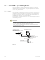
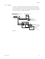

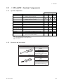

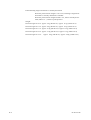
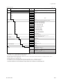
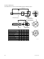
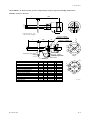
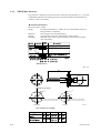
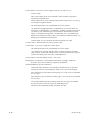

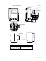
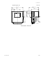


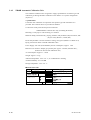

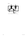

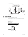
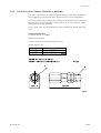
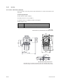
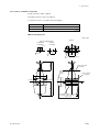

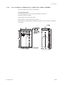
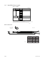

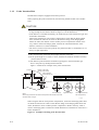
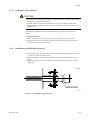


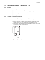
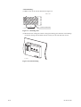
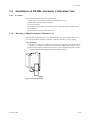
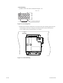


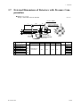
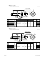


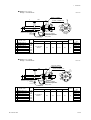


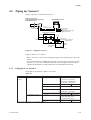
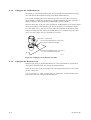


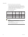
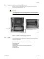
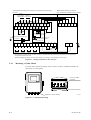
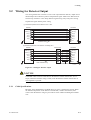
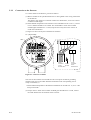


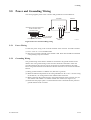
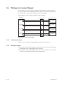
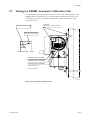


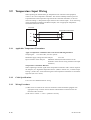

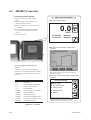
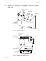

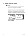
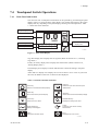
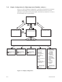
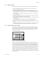
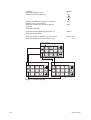
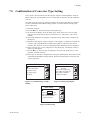

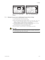
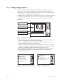
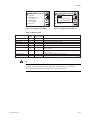
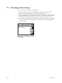

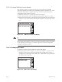
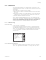
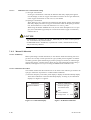
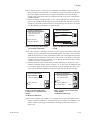


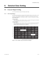


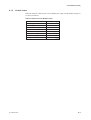
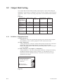


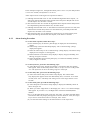
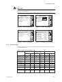

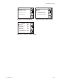
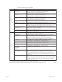


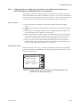

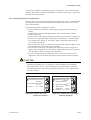
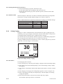
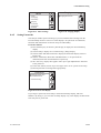

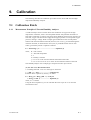
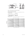


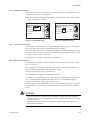
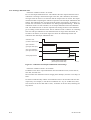

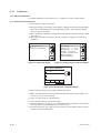


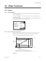


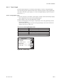
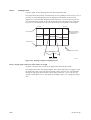
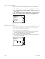

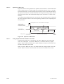


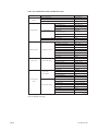
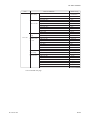

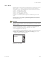
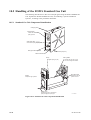


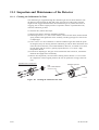
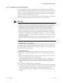


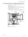
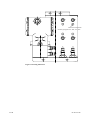


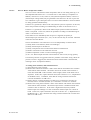


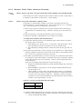
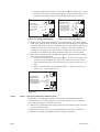

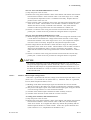


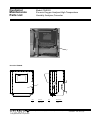
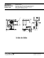


![Model SC450G [Style: S2] Conductivity](http://vs1.manualzilla.com/store/data/005772923_1-d910951678550c5451dfdc47fd4527d0-150x150.png)