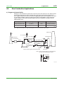
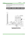
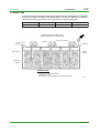
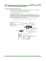
1
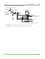
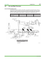
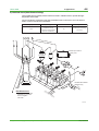
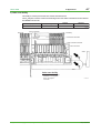
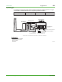
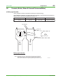
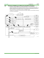
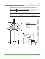
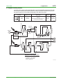
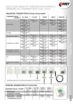
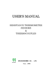
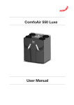
Technical Information TI 11M12A01-01E ZR22G, ZR402G Direct In Situ Zirconia Oxygen Analyzer (Applications Volume) TI 11M12A01-01E 1st Edition, May 2004 (KP) Toc-1 <Int> <Ind> ZR22G, ZR402G Direct In Situ Zirconia Oxygen Analyzer (Applications Volume) TI 11M12A01-01E 1st Edition CONTENTS 1. Overview ................................................................................................. 1-1 2. Installation Guide.................................................................................... 2-1 2.1 3. 4. Selecting an Installation Site .......................................................................... 2-1 System Configurations........................................................................... 3-1 3.1 ZR402G Direct In Situ Zirconia Oxygen Analyzer System Block Diagrams ............................................................................................... 3-1 3.2 Selection According to Use ............................................................................ 3-2 3.3 Examples of System Component Selection Based on Sample Gas Conditions .................................................................................. 3-6 Applications ............................................................................................ 4-1 4.1 Boiler ............................................................................................................... 4-1 a) Package boiler .............................................................................................. 4-1 b) Power generation boiler (Heavy oil, Gas) ....................................................... 4-2 c) Pulverized coal boiler .................................................................................... 4-3 d) Black liquor recovery boiler ........................................................................... 4-4 4.2 Iron and Steel Furnaces .................................................................................. 4-5 a) Iron & steel heating furnace........................................................................... 4-5 b) Hot blast stove (blast furnace facility) ............................................................. 4-6 c) Coke oven facility .......................................................................................... 4-7 d) Soaking pit .................................................................................................... 4-8 4.3 Ceramic, Brick, Glass & Cement Furnaces/Kilns) ........................................ 4-9 a) Rotary type lime kiln ...................................................................................... 4-9 b) Cement kiln (cyclone outlet gas).................................................................. 4-10 4.4 Petroleum Refining and Petrochemical Fired Heaters ................................ 4-11 a) Petroleum refinery process fired heater example ......................................... 4-12 b) Naphtha cracking furnace ........................................................................... 4-13 4.5 Garbage Incinerator ...................................................................................... 4-14 4.6 Non-Combustion Applications ..................................................................... 4-15 a) Oxygen enrichment facility .......................................................................... 4-15 b) Power generation boiler window box ........................................................... 4-16 c) Aeration tank .............................................................................................. 4-17 All Rights Reserved. Copyright © 2004, Yokogawa Electric Corporation TI 11M12A01-01E May 31,2004-00 Toc-2 <Int> <Ind> 4.7 Difficult Measurement Applications ............................................................. 4-18 a) Glass melting furnace (in-furnace gas) ........................................................ 4-18 b) Calcinating furnace ..................................................................................... 4-19 c) Facilities with reducing gas atmospheres ..................................................... 4-19 All Rights Reserved. Copyright © 2004, Yokogawa Electric Corporation TI 11M12A01-01E May 31,2004-00 <Toc> <Ind> 1. 1. Overview 1-1 Overview The EXAxt Zircon Oxygen Analyzer (Model ZR402G) is used to monitor and control the oxygen concentration in combustion gases, in boilers and industrial furnaces, for wide application in industries which consume considerable energy—such as steel, electric power, oil and petrochemical, ceramics, paper and pulp, food, or textiles, as well as incinerators and medium/small boilers. It can help conserve energy in these industries. The ZR402G also contributes to preservation of the earth’s environment in preventing global warming and air pollution by controlling complete combustion to reduce CO2, SOx and NOx. ZR22G Detector uses a high-reliability Zirconia sensor, and its heater assembly can be replaced on site. The detector is mounted, for example, on the wall of a flue and can measure the gases directly. For use in combustion gases at temperatures up to 1400°C, choose the general-use 0.15m long detector, which is combined with ZO21P-H, the high-temperature probe protector. The converter is equipped with an LCD touch screen which has various setting displays, a calibration display, oxygen concentration trend display, with easier operation and improvement of display functions. The converter is equipped with various standard functions such as measurement and calculation as well as maintenance functions including self-test. Analyzer calibration can also be fully automated— and ZR40H, an automatic calibration unit, is available. Choose the detector version which best suits your needs so that an optimal combustion control system can be obtained. Use this TI as a system selection guide and application note. All Rights Reserved. Copyright © 2003, Yokogawa Electric Corporation TI 11M12A01-01E May 31,2004-00 Blank Page <Toc> <Ind> 2-1 2. Installation Guide 2. Installation Guide 2.1 Selecting an Installation Site Improper installation of the detector may cause inaccurate measurement or damage in short-term service. (1) Easy access for inspection and maintenance. (2) Ambient temperature does not exceed 150°C, and the terminal box is not exposed to radiant heat. (3) A clean environment free from corrosive gases. (4) Minimum vibration. Typical good/bad installation examples are shown below for your reference. Instructions for installation Bad Example Duct Good Example Gas Flow (Oriented obliquely against the gas flow) (Installed on a a bend in the duct) (Mounted above the horizontal) Probe Protector Dust Guard Protector (Subjected to condensation) F0201.EPS Installation Site of the Converter (in case of ZR402G) 1. Allows the operator to easily read the display and operated the keys. 2. Easy access for inspection and maintenance. 3. Ambient temperature does not exceed 55°C, and temperature variations are minimal. 4. Humidity is moderate (40 to 75% RH) and no corrosive gases are present. 5. Minimum vibration. 6. Near to the detector. 7. Not exposed to direct sun light. All Rights Reserved. Copyright © 2004, Yokogawa Electric Corporation TI 11M12A01-01E May 31,2004-00 <Toc> <Ind> 2-2 2. Installation Guide Instrument air is not vaailable ZR402G Converter ZR22G Zirconia Oxygen Analyzer, Detector EXA ZR402G Signal (6-core shield cable) Stop valve 100 to ⬃ 240 V AC Heater (2-core) ZO21S Standard gas unit Contact input Analog output, contact output (Digital output HART) Calibration gas ⬃ ➀Install the stop valve securely so that the gas does not leak. ➁Use the standard gas unit. ➂Use a shielded cable for the signal line. F0202.EPS Instrument air is available ZR402G Converter ZR22G Zirconia Oxygen Analyzer, Detector EXA ZR402G Check valve or Stop Valve Signal (6-core shield cable) Heater (2-core) Reference gas ZA8F flow setting unit Needle valve 100 to ⬃ 240 V AC Contact input Analog output, contact output (Digital output HART) Flowmeter Air Set Instrument air Span gas Calibration gas Regulator ➀Install the stop valve or check valve securely so that the gas does not leak. ➁Use the flow setting unit and zero gas cylinder. ➂Use a shielded cable for the signal line. All Rights Reserved. Copyright © 2004, Yokogawa Electric Corporation Zero gas cylinder F0203.EPS TI 11M12A01-01E May 31,2004-00 <Toc> <Ind> 3. 3-1 3. System Configurations System Configurations This section includes two types of system selection guides for direct in situ zirconia oxygen analyzers. The reader should refer first the examples of system selection by application, and then examine the system block diagram and component device overviews. 3.1 ZR402G Direct In Situ Zirconia Oxygen Analyzer System Block Diagrams (1) System Selection Examples, by Application General-purpose detector (0 to 700°C) Common Boiler (fuel oil, gas) High-temperature detector (0 to 1400°C) System types Detector System types L1, L2, L3 D1, (D2) H2, H3 Detector Boiler (pulverized coal, fluidized bed) L2, L3 D4 H2, H3 Boiler (bark, wood scrap) L2, L3 D3, (D1) H2, H3 Heating furnaces & soaking pits L2, L3 Hot blast stove L2, L3 D1 H2, H3 Coke ovens & annealing furnaces L2, L3 D1, (D2) H2, H3 Sintering furnace L2, L3 D1, (D4) H2, H3 Non-ferrous metals Heating, sintering, & melting furnaces L2, L3 D1, (D4) H2, H3 D5, (D6) Ceramic, brick, glass, & cement manufacture Coal kilns (rotary & vertical) L2, L3 D4, (D3) H2, H3 (D5, D6) Cement kilns (cyclone outlet) L2, L3 D4, (D3) H2, H3 Glass melting furnaces (inside furnace) L2, L3 H2, H3 D5, (D6) Glass melting furnaces (flue) L2, L3 H2, H3 D5, (D6) H2, H3 D5, (D6) D5, (D6) Iron & steel H2, H3 D5 D6, (D7) Ceramic firing furnaces L2, L3 Petroleum/ Petrochemical Fired heaters & cracking furnaces L2, L3 D1, (D2) H2, H3 Pulp & paper Black liquor recovery boilers L2, L3 D3, (D4) H2, H3 Other Electrical generating boilers (window box) L2, L3 D1 H2, H3 Garbage & sludge incinerators L2, L3 D1, D3 H2, H3 D5 Oxyten enrichment equipment L2, L3 H2, H3 D7*1 The meanings of these codes are explained on the pages that follow. Note 1: Sampling system is required due to the high pressure. T0301.EPS The symbols such as L1 and D1 used in “the Types of System Configuration and Detector” are only applicable in this Technical Information document for quick reference. They do not appear in other literatures including the bulletin, general specifications, or user’s manual. All Rights Reserved. Copyright © 2004, Yokogawa Electric Corporation TI 11M12A01-01E May 31,2004-00 <Toc> <Ind> 3-2 3. System Configurations (2) System Block Diagram Types : Yes : None Specification Calibration System type No. Name L1 General-purpose using standard gas unit L2 General-purpose using instrument air & zero gas cylinder L3 General-purpose using instrument air & zero gas cylinder H1 High-temperature using standard gas unit H2 High-temperature using instrument air & zero gas cylinder H3 High-temperature using instrument air & zero gas cylinder Remarks Simple type General type Manual Auto T0302.EPS 3.2 Selection According to Use System type No. Examples of selection according to use For monitoring (package boilers, etc.) L1/H1 For high precision measurement for control purposes, etc. L2/H2 For auto calibration options L3/H3 T0303.EPS (1) Type: L1 (simple measurement system) <2> ZR402G Converter <1> ZR22G Zirconia Oxygen Analyzer, Detector EXA ZR402G Stop valve Signal*1 (6-core shield cable) Heater (2-core) 100 to ⬃ 240 V AC <3> ZO21S Standard gas unit Contact input Analog output, contact output (Digital output HART) Calibration gas ⬃ All Rights Reserved. Copyright © 2004, Yokogawa Electric Corporation F0301.EPS TI 11M12A01-01E May 31,2004-00 <Toc> <Ind> 3-3 3. System Configurations (2) Type: L2 (no auto calibration) <2> ZR402G Converter <1> ZR22G Zirconia Oxygen Analyzer, Detector EXA ZR402G Signal*1 (6-core shield cable) Check valve or Stop Valve 100 to ⬃ 240 V AC Heater (2-core) Reference gas Contact input Analog output, contact output (Digital output HART) <3> ZA8F flow setting unit Needle Flowmeter valve Air Set Instrument air Span gas Calibration gas Regulator Zero gas cylinder Note 1: Detector can be selected from among the following No. Check Name Sketch of shade 1 General-purpose detector (with check valve) 2 Detector with probe protector (same as above) 3 Detector with filter (same as above) See the detector section for details concerning detectors. F0302.EPS (3) Type: L3 (auto calibration) <2> ZR402G Converter <1> ZR22G Zirconia Oxygen Analyzer Detector EXA ZR402G Check valve Signal*1 (6-core shield cable) ⬃ 100 to 240 V AC Contact input Analog output, contact output Digital output (HART) Air Set Heater (2-core) Reference gas Flowmeter Needle valve Calibration gas lnstrument air Regulator <3> ZR40H Auto-Calibration unit *2 Zero gas cylinder Note 1: Shield cable; Use shielded signal cables, and connect the shield to the FG terminal of the converter. Note 2: When a zirconia oxygen analyzer is used, 100% N2 gas cannot be used as the zero gas. Use approximately 1% of O2 gas (N2-based). All Rights Reserved. Copyright © 2004, Yokogawa Electric Corporation F0303.EPS TI 11M12A01-01E May 31,2004-00 <Toc> <Ind> 3-4 3. System Configurations (4) Type: H1 (simple measurement system) <1> High-temperature detector ZR22G-015 Air supply (1.5kgf/cm2) Pressure gauge ASSY <2> ZR402G Converter EXA ZR402G Needle valve *2 Signal (6-core shield cable) Ejector ASSY 100 to ⬃ 240 V AC Heater (2-core) Contact input Analog output, contact output (Digital output HART) <3> ZO21S Standard gas unit *3 Calibration gas ⬃ F0304.EPS (5) Type: H2 (no auto calibration, no safety purge) <1> High-temperature detector ZR22G-015 Air supply (1.5kgf/cm2) Pressure gauge ASSY <2> ZR402G Converter EXA ZR402G Needle valve *2 Signal (6-core shield cable) Ejector ASSY 100 to ⬃ 240 V AC Heater (2-core) *3 Reference gas <3> ZA8F flow setting unit Needle Flowmeter valve Contact input Analog output, contact output (Digital output HART) Air Set Instrument air Span gas Calibration gas Regulator Note 2: Selection of Needle valve or Ejector Check Pressure kPa –0.5 Needle valve*1 Ejector ASSY*2 : Necessary Ejector ASSY*3 Zero gas cylinder Note 3: Selection of high temperature probe material Mounting orientation Maximum temperature (°C) Horizontal mounting Vertical downward mounting –0.5 to 0.05 800 SUS310S SUS310S 0.05 to 0.5 1400 — SiC Check 0.5 to 5 *1: K9473XH/K9473XJ *2: E7046EC/E7046EN *3: consult with YOKOGAWA All Rights Reserved. Copyright © 2004, Yokogawa Electric Corporation F0305.EPS TI 11M12A01-01E May 31,2004-00 <Toc> <Ind> 3. System Configurations 3-5 (6) Type: H3 (with auto calibration, with safety purge) <1> High-temperature detector ZR22G-015 Air supply (1.5kgf/cm2) Pressure gauge ASSY <2> ZR402G Converter EXA ZR402G Needle valve *2 Ejector ASSY Check valve Signal*1 (6-core shield cable) ⬃ 100 to 240 V AC Contact input Analog output, contact output Digital output (HART) Air Set Heater (2-core) *3 Reference gas Flowmeter Needle valve Calibration gas lnstrument air Regulator <3> ZR40H Auto-Calibration unit *2 Zero gas cylinder Note 1: Shield cable; Use shielded signal cables, and connect the shield to the FG terminal of the converter. Note 2: When a zirconia oxygen analyzer is used, 100% N2 gas cannot be used as the zero gas. Use All Rights Reserved. Copyright © 2004, Yokogawa Electric Corporation F0306.EPS TI 11M12A01-01E May 31,2004-00 All Rights Reserved. Copyright © 2004, Yokogawa Electric Corporation ZR22G General-purpose detector 2.5 m~3 m Less than 2.5 m Insertion length or less) ZR22G with ZO21R-L General-purpose detector with probe protector (Note 2) [D2] General-purpose detector [D1] Low (0.5 g/Nm3 No Coal, pulverized coal boiler, etc. Yes Abrasive ZR22G with K9471UC or with K9471UA General-purpose detector with dust guard protector or with sic filter [D3] ZR22G with ZO21R-L or with K9471UA General-purpose detector with probe supporter [D4] –5 to +250 kPa (Note 1) High (10 g/Nm3 or less) ZR22G with ZO21R-L or with K9471UA General-purpose detector with probe protector or with sic filter (Note 2) General-purpose detector with protector filter Very high (200 g/Nm3 or less) F0307.EPS (Note 2) Downward oriented mounting preferred. (Note 1) When the pressure in the furnace exceeds 3 kPa, it is recommended that you compensate the pressure. When the pressure in the furnace exceeds 5 kPa, you must perform pressure compensation. For 0.15m probe, 0.5 to 5 kPa. No pressure fluctuation in the furnace should be allowed. Remarks 3.3 0 to 700 Dust level Temperature Pressu re (°C) <Toc> <Ind> 3. System Configurations 3-6 Examples of System Component Selection Based on Sample Gas Conditions 1) Detector and its accessories TI 11M12A01-01E May 31,2004-00 All Rights Reserved. Copyright © 2004, Yokogawa Electric Corporation The high-temperature probe adapter includes a standard material probe. ZR22G-015 ZO21P-H(E7046EC or E7046EN) Auxiliary ejector (or needle valve) Probe Hightemperature detector High-temperature detector High-temperature probe adapter Over 700 Up to 1400 Temperature (°C) Conditions & specifications Mounting orientation Vertical downward Horizontal Inconel 600 Not possible over 1000 SUS310S SiC SUS310S 1000 800 1400 800 Maximum temperature Probe (°C) material Not required Valve ZR22G-015 ZO21P-H- Required ZR22G-015 ZO21P-HE7046EC or E7046EN Not required [D6] Not required Valve [D5] Auxiliary ejector Auxiliary ejector ZR22G-015 ZO21P-H- required Valve Needle valve not supplied [D7] Not required Auxiliary ejector over +0.5 +0.05 to +0.5 Pressure kPa –0.5 to 0 to +0.05 (Note 1) Low (1 g/Nm2 or less ➝ Consult us if higher) Dust level Projection: 200 mm max. 45° (Note 1) Consult us if pressure is less than –5 kPa Remarks F0308.EPS Not standard, please consult us. <Toc> <Ind> 3. System Configurations 3-7 TI 11M12A01-01E May 31,2004-00 ZR402G ZS8C ZR402G EXA ZR402G EXA ZR402G EXA ZR402G Converter ZR402G Device Without auto calibration With auto calibration Use General Explosionproof For monitoring Control/alarming Auto calibration All Rights Reserved. Copyright © 2004, Yokogawa Electric Corporation Not available None *A *A (air set not included) ZA8F- (air set not included) ZR40H (air set not included) ZA8F- Flow setting unit Cylinder: G7001ZC Regulator: G7014XF G7013XF Case: E7044KF (standard gas unit) Cylinder: G7001ZC Regulator: G7014XF G7013XF Case: E7044KF Same as above ⬃ ZO21S--*A Calibration gas F0309.EPS Sometimes required for petroleum and petrochemical, etc. Be sure to use with explosionproof termianl box type detector. This configuration automates the calibration operation. Most common configuration. Solenoid valve unit for handling unburnt gas in available as an accessory system for petroleum or petrochemical fired heaters. Minimum configuration for small boiler monitoring, etc. Remarks <Toc> <Ind> 3. System Configurations 3-8 2) Converter and accessories (flow setting unit, calibration gas, etc.) TI 11M12A01-01E May 31,2004-00 <Toc> <Ind> 4. 4-1 4. Applications Applications This section takes up typical application examples for the zirconia oxygen analyzer. These individual applications are structured as follows. Application examples: Overview of individual devices, and sample points. Sample gas condition examples: Examples of sample gas conditions, and block diagrams and type numbers for zirconia oxygen analyzer systems to be used under those conditions. 4.1 Boiler a) Package boiler This is the most common application. Although the system is generally used for combustion monitoring, there are also cases in which it will be used for VVVF or other such combustion control schemes. Sample point System type Detector Objective Boiler furnace outlet or economizer outlet L1, (L2) D1, (D2) Combustion monitoring T0401.EPS Package boiler Viewport Gas temperature: 150 to 300°C Gas pressure: ⫾0.5 kPa Dust: ⬉1 g/Nm3 Fuel: Fuel oil, kerosene, or gas Gas Flow Combustion Chamber Flame Main Tubes Wall Tubes Top View Blower Burner Steam Drum Soot Blow Nozzle Burner Water Drum Front View All Rights Reserved. Copyright © 2004, Yokogawa Electric Corporation Side View F0401.EPS TI 11M12A01-01E May 31,2004-00 <Toc> <Ind> 4-2 4. Applications b) Power generation boiler (Heavy oil, Gas) This is a large-scale facility in which use for combustion control is more common than for combustion monitoring. In cogeneration, the majority of cases involve measurement at a single point. In electric power companies, measurements are performed at multiple points in a single flue. Sample point System type Detector Objective Boiler furnace outlet or economizer outlet L2, L3 D1, (D2) Combustion monitoring O2 control T0402.EPS Power generation boiler Temperature: 250 to 350°C Pressure: –0.1 to –0.8 kPa Dust: ⬉1 g/Nm3 Fuel: Heavy oil (crude), gas High Pressure Steam Medium Pressure Steam Reheater Economizer Electric Precipitator Air Preheater Heavy Oil Forced Draft Fan Gas Fuel Pump F0402.EPS All Rights Reserved. Copyright © 2004, Yokogawa Electric Corporation TI 11M12A01-01E May 31,2004-00 <Toc> <Ind> 4-3 4. Applications c) Pulverized coal boiler These are almost always large facilities such as power generation boilers; the O2 analyzer is used for combustion monitoring and combustion control. Since the exhaust gas entrains a rather large amount of ash dust, a detector with dust protector will be used. Sample point System type Detector Objective Economizer outlet (economizer, feedwater afterheater) L2, L3 (detector with probe protector) D4 Combustion monitoring O2 control T0403.EPS Steam Dust Guard Drum Superheater Horizontal Superheater Economizer Fuel Air Heater Exhaust Gas Boiler Main Unit Electric Precipitator High Density Dust Ash Centrifugal Force Ash : Optimum mounting position Dust Flow Direction : Second best mounting position Pulverized coal boiler Abrasion Due to Dust Probe Pipe Probe Protector Gas temperature: 300 to 400°C Gas pressure: –1.5 to +1.5 kPa Dust: Approximately 15 g/Nm3 Fuel: Pulverized coal F0403.EPS All Rights Reserved. Copyright © 2004, Yokogawa Electric Corporation TI 11M12A01-01E May 31,2004-00 <Toc> <Ind> 4-4 4. Applications d) Black liquor recovery boiler The spent liquor in a pulp production process is commonly referred to as “black liquor”. The sodium carbonate and sulfate components in this black liquor are recovered by burning it and using the heat to generate steam. The oxygen analyzer is used to monitor or control the combustion in the combustion facility (boiler). Since the exhaust gas includes large amounts of dust (hydrated sodium sulfate) and water vapor, a detector with filter is selected. Sample point System type Detector Objective Economizer: Outlet (economizer, feedwater preheater) L2, L3 (detector with filter) D3, (D4) Combustion monitoring T0451.EPS Black liquor recovery boiler Gas temperature: 170 to 200°C Gas pressure: +2 kPa Dust: 6 to 15 g/Nm3 Main dust components: Na2SO4⬉90% Na2CO3⭌10% F0451.EPS All Rights Reserved. Copyright © 2004, Yokogawa Electric Corporation TI 11M12A01-01E May 31,2004-00 <Toc> <Ind> 4.2 4-5 4. Applications Iron and Steel Furnaces a) Iron & steel heating furnace These furnaces are for the heating of steel slabs, and generally the measured gas is at a high temperature of 1000°C or above. The oxygen concentration is controlled to a low level to prevent oxidation of the slabs. These are also some cases in which there is some amount of CO in the gas, and in which magnetic oxygen analyzers or infrared type CO analyzers are used. Sample point System type Detector Objective Preheat zone, heating zone, soaking zone H2, H3 D5 Combustion monitoring T0452.EPS Iron & steel heating furnace Temperature: 900 to 1400°C Pressure: 0.03 to 0.05 kPa Dust: Minute Fuel: Gas All Rights Reserved. Copyright © 2004, Yokogawa Electric Corporation F0452.EPS TI 11M12A01-01E May 31,2004-00 <Toc> <Ind> 4-6 4. Applications b) Hot blast stove (blast furnace facility) The hot blast stove is a facility used to heat the air used in a blast furnace to provide the hightemperature hot air blast. The air is heated by combustion of the gas generated from the coke ovens. The O2 analyzer is used to control or monitor this combustion. Sample point System type Detector Objective Duct L2, L3 (If pressure is high, a pressure compensated detector is selected.) D1 Combustion monitoring O2 control T0404.EPS Purifie d Gas Bleede r Tube Dust Precipitator Furnace Top Pressure Recovery Unit Blast Furnace Hot Blast Stove Waste Heat Recovery C- ga Hot blast stove Temperature: 20 to 350°C Pressure: 3.5 to 10 kPa Dust: 50 mg/Nm3 Fuel: Gas s Co mb us tio nB low ers F0404.EPS All Rights Reserved. Copyright © 2004, Yokogawa Electric Corporation TI 11M12A01-01E May 31,2004-00 <Toc> <Ind> 4-7 4. Applications c) Coke oven facility This facility is used to produce the coke used in the blast furnace. The O2 analyzer is used to monitor the exhaust gas from the heater combustion used for destructive distillation of the coal. Sample point System type Detector Objective Flue L2, L3 D1, (D2) Combustion monitoring T0405.EPS Dust Fuel Coking Chamber Backstay Combustion Chamber Combustion Chamber Heat Protection Chamber Rich Gas Tube Stack Lean Gas Tube Flue Coke oven facility Temperature: 250 to 350°C Pressure: 0.1 to 0.3 kPa Dust: 100 mg/Nm3 Fuel: Gas All Rights Reserved. Copyright © 2004, Yokogawa Electric Corporation F0405.EPS TI 11M12A01-01E May 31,2004-00 <Toc> <Ind> 4-8 4. Applications d) Soaking pit The soaking pit is a type of furnace used to maintain the ingots at a constant temperature. Oxygen concentration is controlled at a low level to suppress ingot surface oxidation. Sample point System type Detector Objective Ahead of recuperator H2, (H3) D5 Combustion monitoring T0406.EPS Cover Remover Preheat Air Duct Recuperator Burner Furnace Cover Combustion Chamber Furnace Bed Material Ingot Damper Cinder Removal Device Stack Furnace Bed Beam Exhaust Gas Port Cinder Transport Car Construction of unidirectional top section combustion soaking pit. Soaking pit Temperature: 1000 to 1200°C Pressure: 0.03 to 0.05 kPa Dust: 0.5 g/Nm3 Fuel: Gas All Rights Reserved. Copyright © 2004, Yokogawa Electric Corporation F0406.EPS TI 11M12A01-01E May 31,2004-00 <Toc> <Ind> 4.3 4-9 4. Applications Ceramic, Brick, Glass & Cement Furnaces/Kilns) a) Rotary type lime kiln The O2 analyzer is used for combustion monitoring to conserve energy. Careful attention to detector mounting position and orientation is required due to the presence of large amounts of abrasive particulates and intrusion air. Sample point System type Detector Objective Kiln end L2, L3 (H2, H3) D4 (D3, D5, D6) Combustion monitoring T0407.EPS Raw Materials Intrusion Air Exhaust Gas Intrusion Air Exhaust Gas Exhaust Gas Rotary type lime kiln Temperature: 250 to 500°C*1 Note 1: Depending on the kiln, there will be cases when the temperature at the measuring point will be 600°C or greater (600 to 750°C). Under these conditions, the high-temperature type should be used. All Rights Reserved. Copyright © 2004, Yokogawa Electric Corporation F0407.EPS TI 11M12A01-01E May 31,2004-00 <Toc> <Ind> 4-10 4. Application b) Cement kiln (cyclone outlet gas) Cement production consumes approximately 100 liters or more of fuel (heavy oil) per ton of cement. Thus, combustion management by means of O2 analyzers has become a critical element. There are cases in which O2, CO, and CO2 measurements are performed using a sampling system at the kiln outlet. Sample point System type Detector Objective Cyclone outlet L2, L3 D4, (D3) Combustion monitoring T0410.EPS Cement kiln Temperature: 350 to 400°C Pressure: –3 to 5 kPa Dust: ⭌200 g/Nm3 CO: ⭌0.2% F0410.EPS All Rights Reserved. Copyright © 2004, Yokogawa Electric Corporation TI 11M12A01-01E May 31, 2004-00 <Toc> <Ind> 4.4 4. Applications 4-11 Petroleum Refining and Petrochemical Fired Heaters In petroleum refining and petrochemical plants fired heaters are so numerous that you could almost say that there is one in almost every process. Also, since a site consists not of just a single petroleum refining process but rather of ten or more processes, this means that you have that many fired heaters, too (located at the arrows in the diagram above). In addition to the fired heaters, there will also be a number of boilers. Thus combustion monitoring (or control) is a vital element. F0411.EPS All Rights Reserved. Copyright © 2004, Yokogawa Electric Corporation TI 11M12A01-01E May 31, 2004-00 <Toc> <Ind> 4-12 4. Application a) Petroleum refinery process fired heater example There are two possible locations for the sample point in fired heaters for petroleum refining and petrochemicals: in the stack, or in the vicinity of the furnace outlet (convection zone). Stack L2, L3 D1, D2 Furnace outlet (convection zone) H2, H3 D5, D6 Explosion proof type with terminal box may also be selected. T0411.EPS 1 2 Name Temperature °C Stack Convection Approx. 300 to 500 Approx. 600 to 900 T0412.EPS 1 Inlet Inlet Outlet Inlet Steam Superheater Section Process Fluid Preheat Section 1 2 3 4 5 6 Furnace Window Box Air Preheater Stack Draft Blower Exhaust Blower Radiant Heating Section 2 Steam Superheater Section Convection Section Outlet Petroleum refinery process fired heater 1 4 3 Outlet 2 5 All Rights Reserved. Copyright © 2004, Yokogawa Electric Corporation 6 F0412.EPS TI 11M12A01-01E May 31, 2004-00 <Toc> <Ind> 4-13 4. Applications b) Naphtha cracking furnace This is the first process in a petrochemical facility, in which the Naphtha supplied from the petroleum refinery is heated and cracked to produce a variety of products. There will be not just one but rather anywhere from six to twelve fired heaters, each with its own stack. Analyzer installation locations 1 2 Sample point System type Detector Objective Stack or convection L2, L3 H2, H3 Explosionproof type external terminal box may also be selected D1, D2 D5, D6 Combustion monitoring Fired heaters Gas Pressurization Unit T0413.EPS Naphtha Gasoline Fractionater Demethanizer 1 Gasoline Naphtha Heater Inorganic Oil Methane Rich Gas Hydrogen Rich Gas Propylene Ethylene De-ethanizaer Acetylene Lightener Ethylene Fractionater Depropanizer Propylene Fractionater Ethane Heater Debutanizer 2 Gasoline Propane H Naphtha cracking furnace Temperature: Stack: 300 to 600°C Convection: 110 to 600°C Pressure: –0.2 to 0 kPa Dust: 1 g/Nm3max. All Rights Reserved. Copyright © 2004, Yokogawa Electric Corporation F0413.EPS TI 11M12A01-01E May 31, 2004-00 <Toc> <Ind> 4.5 4-14 4. Application Garbage Incinerator This is a facility to handle by incineration the combustible waste generally contained in municipal garbage. The exhaust gas of the incinerator outlet contains large quantities of dust and corrosive gasses, and a large water vapor component. Yokogawa should be consulted concerning the installation of the unit. Sample point System type Detector Objective Incinerator outlet (gas cooler outlet) H2, H3 Note: depending on the conditions at the sample point, a sampling type system may be required. D5 Combustion monitoring Scrubber outlet (or stack) L2, L3 D1, (D3) Combustion monitoring T0414.EPS Air Preheater Extraction Blower Control Oil Gun Scrubber Electric Denitration Precipitator Tower Startup Burner Measured Feed Fluidized Bed Furnace Cyclone Water Sewage Sludge Water Fluidized Bed Incinerator Plant Deconsolidator Dust Heavy Oil Auxiliary Blower Hot Blast Furnace Pressurizing Blower Garbage incinerator Incinerator outlet: 700 to 750°C Exhaust gas temperature: 700 to 750°C Dust: 20 to 30 g/Nm3 Exhaust gas components: SOx Several hundred ppm HCl 100ppm Scrubber outlet Exhaust gas temperature: 80 to 120°C Dust: 0.1 g/Nm3 maximum F0414.EPS All Rights Reserved. Copyright © 2004, Yokogawa Electric Corporation TI 11M12A01-01E May 31, 2004-00 <Toc> <Ind> 4.6 4-15 4. Applications Non-Combustion Applications a) Oxygen enrichment facility Although in most combustion systems air is used as-is, there are cases such as in blast furnaces in steel plants where the air will be enriched with oxygen gas to raise efficiency. When this is done, oxygen analyzers are used to monitor the oxygen generation unit (air separator, etc.), and/ or to check the condition of the mixing with the air in later process stages. In these cases, the oxygen analyzer will be measuring values higher than the concentration of oxygen in the air (approximately 21%). Sample point System type Detector Objective Oxygen supply line Oxygen compressor outlet H3 (Note 1) Note 1 Operational monitoring Air-oxygen mixing line H3 (Note 1) Note 1 Operational monitoring T0415.EPS Note 1: Measurement will be done using a sampling system, since all the points are at high pressure. Intake Tower Air 75 to 100%O2 75 to 100%O2 Blast Furnace 20 kPa Air Compressor Oxygen Gas Compressor 490 to 780 kPa 490 kPa Oxygen Generation Unit (Air Separation Unit) Hot Blast Stove Blast Furnace Blower Air 420 kPa Blast Furnace Oxygen Enrichment Example 0 to 50%O2 Note 1: Due to the high pressure, measurement will be done with a sampling type system. Regulator Valve or Needle Valve F0415.EPS All Rights Reserved. Copyright © 2004, Yokogawa Electric Corporation TI 11M12A01-01E May 31, 2004-00 <Toc> <Ind> 4-16 4. Application b) Power generation boiler window box In large boilers such as those for power generation, part of the combustion exhaust gas is recycled to the combustion intake, and the oxygen concentration in the recycled gas is monitored so that it does not drop too low. The analyzer range will be a partial range that includes the atmospheric oxygen concentration, such as 15 to 22% O2. Sample point System type Detector Objective Window box L2, L3 D1 (Note) O2, control alarm T0416.EPS Note 1: The ZO21DW (terminal box explosionproof type detector; pressure compensated type) or the ZR22G (pressure compensated type) will be used. These are many cases in which the AV8C averaging converter will be used. Power generation boiler window box Temperature: Max. 550°C Pressure: –5 to 20 kPa F0416.EPS All Rights Reserved. Copyright © 2004, Yokogawa Electric Corporation TI 11M12A01-01E May 31, 2004-00 <Toc> <Ind> 4-17 4. Applications c) Aeration tank In one type of sludge processing, oxygen gas is introduced into the processing tanks to maintain the dissolved oxygen concentration in the sludge liquid at a proper level. Efficiency is checked by measuring the oxygen concentration in the exhaust gas from the processing tank. Sample point Exhaust line System type L2, L3 Detector Objective D1 Efficiency monitoring & alarm T0417.EPS Activated Sludge Processing Facility (Surface Aeration System Aeration Tank) Gas Recycle Compressor Control Valve Oxygen Agitator Exhaust Mixed Liquids Waste Water Returned Sludge Aeration tank Temperature: Normal temperature Pressure: 0 to 1 kPa Concentration: Approximately 50% O2 (0 to 100% range) All Rights Reserved. Copyright © 2004, Yokogawa Electric Corporation F0417.EPS TI 11M12A01-01E May 31, 2004-00 <Toc> <Ind> 4.7 4-18 4. Application Difficult Measurement Applications a) Glass melting furnace (in-furnace gas) Oxygen concentration in glass melting furnace stacks can be measured with no problems the same as in other general combusion exhaust gas applications. Glass melting furnace (stack): Temperature 0 to 600°C System block diagram type No: L2, L3 On the other hand when we come to measurement of the gas inside the furnace, continuous measurement with a direct in-situ zirconia oxygen analyzer (high-temperature system) is either extremely difficult or impossible due to the dust and fumes from the components of the glass. However, since continuous measurements are being performed in some cases by the method shown in the diagram, we offer this for your reference. Glass melting furnace configuration & with detail of ZR22G installation 1 2 3 4 Temperature: Norm. 1,200°C Max. 1,300°C Fuel: Butane gas O2: ⬎5% Dust level: Normal...Low During material charging...High 3 to 4 cycles/hour Filter Fiber Flux Bulk Replace Periodically (Note 1) ZR22G (with K9471UA) ZO21P-H Note 1: High-temperature detector with probe adapter, with hightemperature probe (pipe) removed. Hot Water Partial Side View Exhaust Gas Probe (alumina, etc.) Of non-reducing material, treated as a consumable item Pulled by Hood IDF Cover Sampling Port Burner Material Charging Inlet F0418.EPS All Rights Reserved. Copyright © 2004, Yokogawa Electric Corporation TI 11M12A01-01E May 31, 2004-00 <Toc> <Ind> 4. Applications 4-19 b) Calcinating furnace Exhaust gas oxygen concentration measurement for fluidized-bed calcination roasting furnaces, sulfur combustion furnaces and other such furnaces which burn sulfur-containing materials or elemental sulfur presents sample conditions such as the following, so direct-in-situ type zirconia oxygen analyzers cannot be used for measurement. Corrosive gas in exhaust gas: SO2 7 to 18% Note, however, that the Yokogawa direct in situ type zirconia oxygen analyzers are fully capable of measurement in exhaust gases containing SO2 concentrations up to 5000ppm. c) Facilities with reducing gas atmospheres The term “reducing gases” refers to those gases which react with metal oxides to reduce them either to metal or to oxides of a lower degree of oxidation. These gases are composed of a reducing component, of which H2 is the primary example, and an inert gas component such as N2. These reducing gases are used for purposes such as protecting metal surfaces from oxidation or dacarbonization during heat treatment, or to improve certain properties. If an attempt is made to use a direct in-situ type zirconia oxyen analyzer in such a metal treatment furnace, the combustible gas (reducing gas) and oxygen in the sample gas will incite a combustion reaction like that shown below in the high-temperature cell section (generally above 600°C), causing a negative measurement error, so that measurement is generally impossible under these conditions. 2CO+O2➝2CO2 2H2+O2➝2H2O CH4+2O2➝CO2+2H2O Reference Bulletin 11M12A01-01E GS 11M12A01-01E All Rights Reserved. Copyright © 2004, Yokogawa Electric Corporation TI 11M12A01-01E May 31, 2004-00 Blank Page i <Toc> <Ind> Inquiry Sheet for Models ZR22G, and ZR402G Direct In Situ Zirconia Oxygen Analyzer Please place checkmarks in the appropriate boxes and fill in the necessary information in the blanks. 1. General information Customer Object : indication record control alarm Destination of delivery Fuel : gas oil coal Plant name Power requirements V AC Hz Measurement points 2. Process conditions 2.1 Measurement gas components 2.2 Oxygen concentration Nor. Min. Max. vol% O2, 2.3 Temperature Nor. Min. Max. ⬚C, 2.4 Pressure Nor. Min. Max. kPa, 2.5 Gas flow Nor. Min. Max. m/sec, 2.6 Dust type, Size Nor. Min. quantity g/Nm3, 2.7 Corrosive gas No gas , quantity ppm, , quantity ppm, , quantity ppm, , quantity ppm, 2.8 Combustible gas No gas m Gas Gas 2.9 Others 3. Installation site conditions 3.1 Ambient temperature 1. Around Probe temp. from 3.2 Vibration No vibration Vibration ⬚C, to 2. Around Converter temp. from to ⬚C Furnace Stack Others Horizontal Vertical Others Indoor Outdoor Covered 3.3 1 Probe installation location 2 Probe position 3 Probe insertion length (m) (Note) 0.4, 0.7, 1.0, 1.5, 2.0, 2.5, 3.0, 3.6, 4.2, 4.8, 5.4 4 Flange DIN ANSI 3.4 Instrument air supply Cannot be used. Can be used. 3.5 Converter location Indoor Outdoor Covered (under roof) meters 3.6 Cable length between probe and converter Manual 3.7 Calibration method Others kPa Automatic (Note) 3.6m or more is available only in the U.S. 4. Quotation data Quotation Probe Model ZR22G General-use Probe Model ZO21P-H High Temperature Use Probe Adapter Qantity Description Refer to the GS11M12A01-01E for probe selection. E7046EC /E7046EN Auxiliary Ejector for high temperature use. Options (for general use) Model ZO21R Probe Protector for Oxgen Analyzer K9471UA Filter for Oxgen Analyzer Model ZR402G Separate type Analyzer, Converter Model ZO21S Standard Gas Unit Model ZA8F Flow Setting Unit Select any one of ZO21S, ZA8F, ZR40H. Model ZR40H Automatic Calibration Unit L9852CB /G7016XH Stop Valve K9292DN /K9292DS Check Valve Not required if probe options are specified. G7011XF /E7040EL, G7004XF/K9473XG Air Set G7013XF /G7014XF Pressure Regulator ZR22A, ZR202A Heater Assembly (Spare Parts) T0418.EPS All Rights Reserved. Copyright © 2004, Yokogawa Electric Corporation TI 11M12A01-01E May 31, 2004-00 Blank Page