1
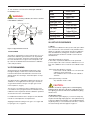
User’s
Manual
Model AC4/AC8 Automatic Calibration Unit
For Use With AV550G
Oxygen Analyzer Averaging Converter
I. Introduction.................................................................................................3
II. Overview......................................................................................................3
2.1 Models AC4/AC8 Multi-Channel Automatic Calibration................................................................3
III. Installation....................................................................................................3
3.1
3.2
3.3
3.4
Location...........................................................................................................................................3
Mounting..........................................................................................................................................3
Gas Sources....................................................................................................................................4
Piping...............................................................................................................................................5
IV. Wiring...........................................................................................................6
4.1 Wiring the AC4/AC8 to the AV550G Averaging Unit.......................................................................6
4.2 Pressure Switch, M1133AR, Set Point Procedure..........................................................................6
V.
Initial Flow Rate Set-Up..............................................................................7
5.1
5.2
5.3
5.4
Checking for Leaks..........................................................................................................................7
Setting for Reference Air Flow........................................................................................................7
Balancing Pressure Drops in the Cal Lines....................................................................................8
Calibration Check............................................................................................................................9
VI. Programming...............................................................................................9
VII. Set-Up Menus for Calibration from the AV550G Averaging Unit............9
7.1 Modes..............................................................................................................................................9
7.1.2 Calibration Setup Mode..............................................................................................................10
7.1.3 Zero Gas Concentration.............................................................................................................10
7.1.4 Span Gas Concentration............................................................................................................10
VIII.Maintenance..............................................................................................12
IX. Trouble shooting........................................................................................12
9.1 Typical Calibration Problems.........................................................................................................12
X. Spare Parts and Accessories...................................................................13
10.1 Spare Parts..................................................................................................................................13
10.2 Accessories ................................................................................................................................14
10.2.1 Zero Gas Regulator, M1132ZX.........................................................................................15
10.2.2 Pressure Regulator, M1132KD.........................................................................................15
10.2.3 Pressure Gauge, M1132CG.............................................................................................15
10.2.4 Zero Gas Pressure Switch, M1133AR..............................................................................16
10.2.5 Fuses, M1132HG..............................................................................................................16
Appendix A Wiring Diagram AC4 to AV550 to ZR22G...................................17
Appendix B Wiring Diagram AC8 to AV550 to ZR22G...................................19
IM 11M6D2-02E-A
2nd Edition
3
I. INTRODUCTION
This manual details the operating instruction for the Yokogawa Model AC4/AC8 Automatic Calibration Unit, and the
integration with the AV550G Zirconia Oxygen Averaging
Converter.
IMPORTANT
The maximum input pressure for the span and zero gases is 35
psig. Exceeding 35 psig may result in damage to the AC4/AC8.
II. OVERVIEW
The AC4/AC8 Automatic Calibration System is designed to
work with the AV550G Oxygen Averaging Converter, providing accurate, automatic or semi-automatic calibration of the
ZR22 Zirconia Oxide Detector. The AC4/AC8 is assembled
with plumbing, flow control hardware and internal solenoid
wiring necessary to calibrate up to four or eight probes
respectively. The end user need only provide plumbing to the
individual probes, calibration gases, and interconnection wiring between the calibration unit and the converter.
Initial setup of the auto cal unit is further simplified by the
use of manual overrides for all solenoids. The overrides,
coupled with the flow regulation for each probe, allow for
fast balancing of each calibration line. Each probe also has
its own flow meter and flow control for the reference air flow.
2.1 Models AC4/AC8 Multi-Channel Automatic
Calibration
UStandard Specifications
Operating Pressure: 20 psi
Maximum Pressure: 35 psi
Flow meter range: 0.15 to 1 LPM (separate flow meter
for cal gas and reference air)
Flow rate:
Cal Gas – 0.6 LPM;
Reference Air – 0.8 LPM
Cal tubing:
1/4” copper (standard);
1/4: stainless steel (optional)
Gas connection:
1/4” FNPT
Voltage:
110 VAC, 50/60 Hz (standard)
Ambient temp.:
80°C (176°F) maximum
Weight:
Approximately 40 lbs (18 kg)
Construction: Outdoor installation (Indirect sunlight)
Enclosure:
NEMA 4 or NEMA 4X
Reference gas
Consumption:
0.8 LPM per probe
Cal Gas Consumption
(Zero & Span): 0.6 LPM per probe,
during calibration only
NOTE
Model and code
AC4
AC8
-4
-5
AUTO CALIB RATION UNI T FOR AV 550G
4 Cha nnel System
8 Cha nnel System
ENC LOS URE
NEMA 4
NEMA 4X
PL UM BING
-C
Copp er tub ing , brass fittings
-S
Stainless steel tub ing and f ittings
REFE RENC E AI R FL OW MET ER
-R*U
Reference air flow meter
OPT IONS
/SC T
Stainless Steel Tag
III. INSTALLATION
3.1 LOCATION
The following guidelines should be used when selecting a
location for the auto-calibration unit.
1. The unit must be easily accessible for maintenance and
inspections.
2. The unit must be near the ZR22 probes as practical. This
will minimize the length and amount of tubing required for
plumbing.
3. Ambient temperature will not exceed 80°C (176°F).
4. Humidity is moderate and no corrosive gases are present.
5. Minimal presence of vibration.
6. Availability of 120 VAC and clean, dry instrument air.
7. Adequate spacing for reference and zero gas plumbing.
8. Not positioned in direct sunlight.
NOTE
If ambient atmosphere contains corrosive gases or high dust,
the use of air purging is recommended.
3.2 MOUNTING
The unit is designed for wall mounting by securing the four
standoffs with bolts. Allow for sufficient space to connect the
copper or stainless steel lines to both sides of the enclosure.
Input gases (zero calibration gas and instrument air) are
connected to the left side, while all probe connections (cal
lines and reference air) are on the right side, when facing the
unit. Refer to Figure 1 for mounting dimensions and required
clearances.
IMPORTANT
Care must be taken to mount the unit as level as possible to
ensure the accuracy of the flow rates. If the unit is not level, the
flow rates will not be accurate!
Instrument air is used for both span calibration gas and
reference air.
IM 11M6D2-02E-A
4
Figure 3.1: AC4/AC8 Dimensional Drawing
3.3 GAS SOURCES
Zero Gas
Typically, 1% oxygen balanced in nitrogen is used, however,
an oxygen mixture between 0.5% and 8% is acceptable.
NEVER USE PURE NITROGEN FOR ZERO CALIBRATION GAS. A compressed gas cylinder containing the zero
gas is fitted with a dual stage regulator. Zero calibration gas
cylinders with regulators may be purchased from a local
compressed gas supplier. Follow the operation and safety instructions as supplied from your gas supplier. The maximum
pressure of the calibration unit is 35 psi.
Reference Air
The reference air is the same air as the span gas. Thus, the
reference air is also clean dry instrument air. Unlike span gas,
which is use only during calibration, reference air flows to
the back side of the zirconium cell and should be used at all
times.
IMPORTANT
When the instrument air has a nitrogen backup (used for air
failure), instrument air for the reference gas should not be used.
In this instance the probe must use either bottled air (20.6%
oxygen balanced in nitrogen) or natural convection for reference
air flow.
NOTE
The compressed gas cylinder must have the same CGA connection fitting as the dual stage regulator (see accessories).
Span Gas
Typically, a clean dry air source is recommended, such as
instrument air (20.6% oxygen). An in-line filter is recommended to remove any moisture or dirt prior to the calibration unit. A regulator must be attached to the instrument air
source in order to reduce the flow to an appropriate pressure
(35 psig max) prior to reaching the calibration unit.
IM 11M6D2-02E-A
5
3.4 PIPING
/-2ĥDCK?JCLNR
PCDE?Q
PROBE 1
A?J
E?Q
LCK?2V
/-2ĥDCK?JCLNR
PROBE 2
O2 CALIBRATION SYSTEM
INSTRUMENT AIR
PROBE 3
PROBE 4
PROBE 5
ZERO GAS
35 psig MAX
PROBE 6
WMIME?U?
PROBE 7
PROBE 8
Figure 3.2
Piping Gases to the Auto Cal Unit
Piping (or tubing) is required from the instrument air line and
zero gas cylinder to the calibration unit. Standard tubing is _”
O.D. (Outside Diameter) copper or stainless steel. Stainless
steel is preferred, as it is less likely to develop leaks. The
separate tubing for both the instrument air and zero gas are
connected to the two separate 1/4” FNPT brass or stainless
fittings on the LEFT side of the calibration unit.
Piping Gases to ZR22 Probes
The tubing to the ZR22 probes is run from the RIGHT side of
the calibration unit to each of the ZR22 probes as shown in
Figure 2. Quarter inch (1/4”) tubing should be used between
the auto cal unit and the probes. It is important to note 1)
the reference air tubing is connected to the REF IN port
at the probe; 2) cal gas tubing is connected to the CAL
IN port on the probe. The REF IN and CAL GAS ports are
located on the bottom of the ZR22 probe junction box. The
check gas and reference air ports require a 1/4” FNPT fitting.
NOTE
Flexible stainless steel hose is recommended for the connection
between the ZR22 and the tubing.
This will allow for probe movement due to thermal expansion of
the duct.
IMPORTANT
To prevent leakage, all compression fittings should be installed
per manufacturer’s recommendations. In addition to this, a
check valve is usually installed on the cal gas inlet of the ZR22
probe to protect the cal tubing from moisture contamination.
IM 11M6D2-02E-A
6
IV. WIRING
Calibration
Using
Pressure Switch AND Relay
4.1 Wiring the AC4/AC8 to the AV550G Averaging unit
Pre ssure
Switch
Please refer to appendix A for the system configuration
drawing.
YES
Cal Gas
Pre ssure
OK ?
STAR T
NOTE
A 120 VAC relay (included with NEMA 4 enclosure), shown at terminal K1, is required at the AV550G if a pressure switch is used.
This prevents noise caused by a low voltage pressure switch
signal from being run in the same cable as the 120 VAC solenoid
signal.
The relay is prewired as NORMALLY CLOSED (NC) to
contact input #1 at the control card (terminal 7 and 9) of the
AV550G.
Calibration
Status
Pre ssure Switch U sed a s Input to R elay
Solenoid, Relay and Pressure Switch wiring connections
The AC4/AC8 uses 120VAC, 60 Hz for all solenoids. Although two internal 1 amp fuses are provided for the ±120
VAC terminal, an external 5 amp circuit breaker is recommended. Included with each fuse is an LED that is activated
when the fuse is blown. Recommended wiring is 14AWG,
run in conduit. If conduit is not used, wiring should have a
suitable jacket to meet environmental and regulatory codes.
The AC4 unit requires a maximum of 8 conductors, whereas
the AC8 requires 12 conductors.
Relay
Pre ssure Switch
CLOS ED
Relay Energized a nd
OPEN
CALIBRATE
NO
Pre ssure Switch
OPEN
Relay Deenergized
and
CLOS ED
DO NOT
CALIBRATE
Figure 4.2: Calibration Using Pressure Switch and Relay Flow
Chart
The recommended pressure switch configuration is to the
high pressure side of the zero gas regulator. This is preferred
because it gives the earliest warning of a decrease in zero
gas pressure. The switch is threaded into the high pressure purge port of the dual stage regulator on the zero gas
cylinder.
4.2 Pressure Switch, M1133AR, Set Point Procedure
For the AC4/AC8 Autocal units, a gas pressure set point is
used to indicate that the calibration gas (zero gas) is low.
Pressure Switch M1133AR is a cylindrical style pressure
switch which uses a diaphragm or piston sensor to detect a
pressure change. The recommended set point is 200 psi on
the fall. At the predetermined set point, a SPST switch actuates, converting a pressure signal into an electrical signal.
M1132ZX Dual
Stage Regulator
M1133AR
Pressure Switch
Figure 4.1 AV550G Input Contact Screen
WARNING
When the relay is deactivated, the unit will not calibrate. The
relay remains closed unless a 120 VAC source is connected to
energize it. Terminal 7 of the relay provides 120 VAC. Neutral
voltage is connected to terminal 2 of the relay from the AC4/AC8
calibration unit.
The relay switch is designed to OPEN when energized as
depicted in the flow diagram shown in Figure 4.2. A pressure
switch input completes the 120 VAC signal used to energize
the relay, which is wired at the calibration unit as Normally
Open (NO), where Open = Low or Zero tank pressure. The
AC4/AC8 unit is prewired with the jumper in place, so that
the relay will be energized and OPEN. However, if the pressure switch input is used, then remove the jumper between
the terminals labeled PS at the calibration unit’s terminal
strip, and attach the pressure switch. The pressure switch is
wired as normally open.
Figure 4.3: Pressure Switch and Dual Stage Regulator
The following procedure is required to adjust the set point:
1. Thread the pressure switch into the high pressure gauge
port on the regulator.
2. With power disconnected, slide the cover on the switch
toward the electrical termination while twisting it to overcome friction.
3. Connect the power to the terminal or leads.
4. Insert a flat head screwdriver (1/8”) into the adjustment
slot and turn counterclockwise to increase the setting or
clockwise to decrease the setting.
IM 11M6D2-02E-A
7
For setting on fall, apply pressure equal to normal system
operating pressure. Reduce source pressure to set point
value. Turn the adjustment clockwise until switch “clicks”
[circuit across N.C. (black) and COM (white) closes]. For
setting on rise, apply desired pressure and turn adjustment
left until switch “clicks” [circuit across N.O. (red) and COM
(white) terminal closes].
5. After completing adjustments, slide the cover closed over
the adjustment compartment. Recheck the set point value.
6. Wire the pressure switch Normally Open to the AC4/AC8
terminals at the calibration unit that are labeled PS. Remove
the jumper across the PS terminals.
V. INITIAL FLOW RATE SETUP
5.1 CHECKING FOR LEAKS
Before considering your calibration unit operational, it is a
good idea to check for leaks along the full distance of the cal
line tubing. Additionally, perform a cal check to confirm that
the gases are plumbed correctly to each probe.
1. Plug all the cal and reference air lines at the probes. This
requires disconnecting the fitting at the ZR22 Probe and
plugging the tubing.
2. Set the flow rate of the Zero Gas and Instrument Air to 20
psig using the regulators.
3. Locate the block solenoid shown in Figure 5. Using a flat
tip screwdriver, turn the manual override screw on the block
solenoid to the 90º position as shown in Figure 5.2.
4. Turn the channel solenoid valve’s manual override screw
to the horizontal, or ON (NOT NORMAL) position for Uall
probes in use. See Figure 5.1 and 5.3.
5. Apply leak detection spray on all compression fittings and
bends of the cal line tubing for all probes. Spray both the
reference air and cal gas line(s).
6. Inspect the full length of the cal lines to determine if there
is a leak. Repair any leaks.
7. After repairing the leaks, if any, turn all probe channel
solenoids and the block solenoid to the NORMAL position as
shown in Figure 5.2 and 5.3.
8. Unplug tubing at the ZR22 probe(s) and reconnect.
5.2 SETTING REFERENCE AIR FLOW
Locate the reference flow air meters in Figure 5.1. Adjust the
black flow adjustment knob on each reference air flow meter
to 0.8 LPM (800cc/min).
NOTE
Reference air flow should be adjusted before the calibration
adjustments are made.
CH AN NE L MA N IF OLD
WIT H M ANU AL
O VE R RIDE AN D
FLOW A DJU STE R
M1132BY (4 Chan nel)
M1132BZ (8 C ha nne l)
Figure 5.1 AC8 Parts Listing
IM 11M6D2-02E-A
8
6. Turn the manual override on the channel solenoid for the
probe to the OFF (normal) position.
5.3 BALANCING PRESSURE DROPS IN THE CAL LINES
For accurate calibrations, the auto cal system must provide a
fixed flow of zero gas and span gas (0.6 LPM pr 600cc/min).
To do this, the pressure drop from the AC4/AC8 to each
probe must be the same regardless of the length of tubing
run or number of probes. To balance the pressure drops,
perform the following steps:
NOTE
Perform all adjustments with a flat tip screwdriver.
1. Ensure gas and instrument air are plumbed to the auto cal
unit. Pressure should be set at 20 psig ± 2 psig.
2. Locate the block solenoid shown in Figures 5.1 and 5.3.
Using a flat tip screwdriver, turn the manual override screw
on the block solenoid to the vertical position, as shown in
Figure 5.2.
ZERO/SPAN
SOLENOID
BLOCK
SOLENOID
7. Repeat steps 4, 5, and 6 for the remainder of the probes
that are being used.
NOTE
DO NOT use the cal gas flow meter’s adjustment knob to make
this flow rate adjustment. Use the individual channel’s flow
adjustment screw to adjust for varying pressure drops in the
tubing runs.
8. After all flow rates have been set manually to 1 LPM, turn
the channel solenoid for the probe with the longest tubing
run back ON to the manual override position – making sure
all others are OFF (normal position shown in Figure 5.3). Turn
the cal gas flow meter’s adjustment knob to 0.6 LPM (600cc/
min).
ZERO/SPAN
SOLENOID
BLOCK
SOLENOID
FOR NORMAL OPERATION AND
MANUAL OVERIDE, SCREWS
MUST BE IN THE POSITIONS
SHOWN
MOUNTING
SCREWS
OVERRIDE
NORMAL
Figure 5.2: Zero and Block Solenoid
3. Locate the cal gas flow meter in Figure 5.1. Turn the
black adjuster knob to the maximum open position. This fully
opens the cal gas regulator, allowing precise adjustments of
flow rates.
4. Locate the channel solenoid valve for the probe with the
longest tubing run in Figure 5.1. Turn the manual override
screw to the horizontal, or ON position. Refer to Figure 5.3.
5. Each channel has its own flow adjustment screw located
on the channel solenoid valve as shown in Figure 5.3. Adjust the flow adjustment screw for the probe so that the flow
rate shown on the cal gas flow meter is 1 LPM (1000 cc/min).
NOTE
9. Turn the manual override screw (Figure 5.3) on the zero/
span solenoid (three way solenoid) to the 90º position. This
starts the flow of the zero gas. Adjust the needle valve to
the left of the three-way solenoid so that the flow rate is 0.6
LPM (600cc/min). If 0.6 LPM is difficult to obtain, it will be
necessary to slightly increase the zero gas pressure to the
unit.
WARNING
Do not adjust the cal gas flow meter or the flow adjustment
screw on the individual channel solenoids.
10. Confirm that all channel solenoid overrides for all used
probed are turned back to the normal position as shown in
Figure 5.3.
DO NOT use the cal gas flow meter’s adjustment knob to make
this flow rate adjustment. If necessary, increase the air pressure.
IM 11M6D2-02E-A
9
11. Turn the block solenoid and the zero/span solenoid to
the normal position.
Item
Mode
Points
Zero gas conc.
Span gas con.
Hold time
Cal. time
Interval
Starting date
Starting time
WARNING
If reference air is used during calibration, the reference air must
remain ON after calibration.
FLOW ADJUSTMENT SCREW (PRESET)
FOR NORMAL
OPERATION THE
MANUAL
OVERRIDE SCREW
MUST BE IN THE
VERTICAL
POSITION
FOR OVERRIDE
THE MANUAL
OVERRIDE SCREW
MUST BE IN THE
HORIZONTAL
POSITION
Initial value
Manual
Span-Zero
1.00%
21.00%
3 min. 00 sec.
3 min. 00 sec.
1 days 00 hrs
yy01mm01dd01
hh00mm00
Figure 6.1
MOUNTING SCREW
NORMAL OPERATION
VII. SET-UP PROCEDURES
OVERRIDE
Figure 5.3: Typical Channel Solenoid
5.4 CAL CHECK
The purpose of performing a cal check at this time is to confirm that the calibration gas and reference air are plumbed
correctly for each probe, along with confirming that enough
time was allowed for the cal gas to flow at the probe’s cell
tip. Refer to the AV550G Instruction Manual for calibration
codes and procedures.
VI. PROGRAMMING
7.1 Mode
There are three calibration modes (for zero and span calibration: manual mode, semi-automatic mode (started from the
display or started by contact input) using preset calibration
time and stabilization (settling) time, and auto calibration
at preset intervals. Restrictions related to each mode are
described here.
-When [Manual Mode] is selected:
In this mode, only Manual calibration can be performed.
(Contact input used to start semi-auto calibration has no effect). Auto calibration does not start at auto calibration start
time.
-When [Semi-Auto Mode] is selected:
In this mode, manual calibration or semi-automatic calibration can be performed.
Auto calibration does not start at auto calibration start time.
All programming for the AV550G Averaging Unit is done
through the display module. Please refer to the AV550G
Instruction Manual, IM 11M12D01-01E, Section 9 for additional details. The following is a brief description of setup
procedures.
The ZR22G Probe is calibrated by applying two known gas
standards. In most applications the zero gas is around 1%
oxygen with the balance nitrogen. The span gas is instrument air (20.95 % oxygen).
The zero gas concentration must be certified so the exact
concentration can be programmed into the AV550G memory.
Calibration values required for full auto-calibration operations
are stored in the menu of the AV550G.
Indication check mode of [Auto] cannot coexist with [Auto]
Calibration mode. Therefore, if the mode of indication Check is
set to [Auto], you cannot set the mode of Calibration to [Auto],
and vice versa.
For additional information refer to Chapter 8 of the AV550G
manual for a full explanation of all parameters.
Shipping time default setting for zero gas is 1% oxygen and
for span gas is 21%. Figure 6.1
-When [Auto Mode] is selected:
Any calibration mode is valid.
CAUTION
<Setting Procedure>
1) From the basic panel display, if you touch the Setup key,
the [Execution/Setup] display appears. Select [Maintenance].
2) From the [Maintenance] display, select [CalibrationSetup]
the [Mode] amd you can selct Manual, Semi-Auto, or Auto in
the selection drop down that appears. Figure 7.1.
IM 11M6D2-02E-A
10
7.1.3 Zero Gas Concentration
This sets the oxygen concentration of the zero gas used for
calibration. Enter the value from the label of the corresponding gas bottle.
7.1.4 Span Gas Concentration
This sets the oxygen concentration of the span gas used for
calibration. When the instrument air supply is used as the
span gas, enter 21% O2.
NOTE
Figure 7.1 Calibration Mode Setting
7.1.2 Calibration Setup Procedure
Either Span or Zero or both calibrations can be performed.
Normally select both: Span-Zero.
<Setting Procedure>
From [Maintenance]‡ [Calibration setup] display, select
[Points], then a selection window opens and Span-Zero,
Span or Zero may be selected. Figure 7.2
When the instrument air supply is to be used as a span gas, cool
the gas to -20ºC below the dew point to remove moisture, oil
mist and dust from the air. If this air purification is not performed, the accuracy of the calibration may be affected.
<Setting Procedure>
1) From the [Calibration setup] display, select [Zero gas
conc.], and the numerical data entry is display is displayed.
Enter the oxygen concentration of the zero gas used for calibration. For example, enter 0.98 vol% O2 as [00098].
2) From the [Calibration setup] display, select [Span gas
conc.], and the numerical data entry is display is displayed.
Enter the oxygen concentration of the span gas used for
calibration. For example, enter 21 vol% O2 as [02100].
3) Calibration time setting
If the mode is [Man]:
Select [Hold time]. This is the output stabilization (settling)
time required from calibration end until measurement is
reentered. During this time, the calibration gas is switched to
measurement gas and the measurement gas is allowed time
to stabilize. Setting range is from 00 min. to 60 min 59 sec.
The analog outputs of individual channels which are under
calibration remain Output Hold status from the start of calibration until the end of the stabilization (settling) time, and
their output is not included in the averaging group calculations during this time.
Figure 7.2 Procedures for Setting Calibration Mode.
If the mode is in [Semi-Auto]:
In addition to the above [Hold] output stabilization (settling)
time, there is also a [Cal. Time] setting. This is the setting
time from when calibration gas flow is started until calibration is performed. The same time setting is used for both
Zero and Span calibration. Setting range is from 00 min. to
60 min 59sec. Calibration time and stabilization time, and
analog output status are shown on the calibration timing
chart of Figure 7.3 below. For solenoid valve (SV) piping and
wiring refer to Section 5 of AV550G manual.
IM 11M6D2-02E-A
11
Cal start in
Chan 1 Span CAL
CAL time
Chan 1 Zero CAL
CAL time
Chan 1output hold
Stabilization
Chan 1 output hold
Chan 2 Span CAL
CAL time
Chan2 Zero Cal
CAL time
Chan 2 output hold
Stabilization
Chan 2 output hold
Chan 1 removed from average
Average output
SV-Chan 1 contact
off
on
off
SV- Chan 2 contact
SV- Chan 2 contact
Chan 2 removed from average
span gas on
zero gas on
on
span gas on
zero gas on
CAL start
Figure 7.3
If the mode is [Auto]:
In addition to the above [Hold] output stabilization (settling)
time [Cal. Time] setting, there is also Cal. [Interval], [Start
date] and [Start time]. The Automatic Calibration Interval can
be set in the range 00 days 00 hrs to 255 days 23 hrs once
Auto Calibration starts. It is performed for all installed channels, so the interval needs to be larger than the sum of span
and zero calibration times plus settling tines for all channels.
The Start date and Start time are for the first calibration in
the Auto Calibration cycle (repeated at the calibration interval). To set 2004 June 21 at 1:30 pm, set Start date to:
YY: 04, MM: 06, DD: 21 and Start time to HH: 13, MM: 30.
<Setting Procedure>
1) From the [Calibration Setup] display, select [Timing] and
the display shown in Figure 7.4 appears. In this example,
[Mode] is set to [Auto].
2) Select items and enter numerical values as required.
Figure 7.4 Calibration time setting
NOTE
When setting, keep the following points in mind:
1) When calibration is to be started by a contact input signal,
the contact input signal on the [Input Contacts] display
needs to be defined and enabled.
2) The starting of Auto Calibration may be delayed by the
status of the channel to be calibrated, or by the status of
other channels, as explained by table 7.1.
IM 11M6D2-02E-A
12
3) If the calibration interval is shorter than the sum of the
stabilization time plus calibration time, the second calibration start time will conflict with the first calibration. In such a
case, the second calibration will not be conducted. (When
both zero and span calibrations are to be performed, the
calibration time is double that required for a single (zero or
span) calibration).
4) If the (Calibration) Interval is et to DD: 00, HH: 00 then
auto Calibration will not be performed.
5) If the start date is set before the current date, then Auto
Calibration will not start.
6) [Cal. Time] of [Calibration timing] display will be equalized
to [Check time] of [Semi-auto ind. Chk] display
other
commands
Man. Cal.
SemiAuto
AutoCal
Purging
the
channel
X
Other
channel
CAL
X
Indication
check in
other channel
X
Blowback in Maintenance CAL chan.
other
in warmup
channel
status
X
CAL chan.
in ERR
status
CAL chan.
now
disabled
X
X
X
X
X
X
X
X
X
X
X
X
Wait
Wait
Wait
Wait
Wait
X
X
X
X: Cannot perform calibration
IX. TROUBLESHOOTING
9.1 TYPICAL CALIBRATION PROBLEMS
1) Gas does not flow to the probe.
• If reference air is used, then the reference air flow meters
should show 0.8 LPM at all times. If the reference air flow
meters do not show 0.8 LPM, then confirm that the instrument air has been turned on by checking the regulator gauge
(10to 35 psi).
• Confirm override screws are in the NORMAL mode for the
block solenoid and all channel solenoids.
• Turn block solenoid to the manual position. Cal gas flow
meter should show 0.6 LPM. If cal gas flow meter shows 0
LPM, turn the black knob on the flow meter to open the flow
meter. Set flow rates for all probes as according to procedures shown in Section 5 of this manual.
2) Flow meter will not go to 0.8 LPM for reference air.
Wait: Wait until other command finishes before starting calibration
Table 7.1 When Auto Calibration conflict with Other Commands
VIII. MAINTENANCE
Because of the AC4/AC8 unit’s simplified construction, no
routine maintenance is required, other than replacing the
calibration gas when necessary. When cal gas cylinders are
changed refer back to Section 7.1.2 Calibration Setup Procedure. Failure to perform the Calibration Setup Procedure
upon replacing cal gases will result in an error in the zero
correction values. When changing gases it is also necessary
to check the zero gas flow rate.
It is recommended that periodic inspections are performed
to insure a sufficient supply of calibration gases when the
pressure switch input is not used. Also, periodic checks
verify that the flow rate of the calibration gases, to the individual oxygen detector probes have not been accidentally
changed. It is important that the zero gases flow at a rate of
0.6 LPM (600mL/min.), while the reference air (instrument air)
flows at 0.8 LPM (800mL/min).
Refer to Section 10 of this manual for a listing of spare parts
for the AC4/AC8.
• Turn the flow rate adjustment knob only, NOT the override
screw.
• Only one channel should be in the manual override position. All other probes should be in the normal position.
• Check the pressure regulator at the gas source. If the
pressure is below 14 psi, increase pressure in increments
of 5 psi, and adjust reference flow meters. DO NOT increase pressure to greater than 35 psi. If more than 35 psi
is needed, attempt to move the calibration box closer to the
probes, without compromising safety or the ambient operating temperature of the auto cal unit.
• Tubing outside diameter (O.D.) should not be greater than
1/4” .Tubing runs should not be in a T position, and should
remain separate for each probe.
• Check for leaks at compression fittings. All NPT fittings
should have Teflon tape on the threads to prevent leaks.
3) Flow meter will not go up to 0.6 LPM for cal gas.
• Same solution as above, except make adjustment to the
cal gas flow meter.
4) Wrong gas flowing to the probe.
• Confirm that gases are plumbed correctly at the left side of
the calibration unit.
• Turn the override screw on the three-way solenoid to the
normal position.
• Perform a cal check in semi auto calibration mode. (See
Section 5).
IMPORTANT
When performing an actual automatic or semi automatic calibration, and a calibration alarm occurs, it is necessary to reset
the channel. Instead, recalibrate the channel to remove the calibration alarm. For additional troubleshooting procedures, refer
to the AV550G manual, Section 12.
IM 11M6D2-02E-A
13
X. SPARE PARTS AND ACCESSORIES
10.1 SPARE PARTS
Refer to figure 10.1 for a list of replacement parts for the AC4/ AC8 Auto Calibration Unit.
CH AN NE L MA N IF OLD
WIT H M ANU AL
O VE R RIDE AN D
FLOW A DJU STE R
M1132BY (4 Chan nel)
M1132BZ (8 C ha nne l)
Figure 10.1
1. Zero/Span Solenoid
2. Channel Manifold
M1132GM
M1133BY (4 CHANNEL)
M1133BZ (8 CHANNEL)
3. Needle Valve
M1132GK (BRASS)
M1132BX (STAINLESS STEEL)
4. Reference /Cal Gas Flow Meters
M1132CC (BRASS)
M1132ZC (STAINLESS STEEL)
IM 11M6D2-02E-A
14
10.2 ACCESSORIES
10.2.1 Zero Gas Regulator, M1132ZX
This regulator controls the gas pressure of the zero gas cylinders before it reaches the calibration unit. The dual stage regulator is highly recommended for services which require a near constant delivery pressure as the calibration source decays (See
M1133AR). Air diffusion and absorption, desorption and off gassing are minimized because of its stainless steel construction.
NOTE
This regulator is used on a “zero gas” cylinder with a CGA 580 connection. The Cylinder connection must be CGA580 (used for <5%
oxygen balanced in nitrogen).
FRONT
ISOMETRIC
Figure 10.2 Zero Gas Regulator, M1132ZX
Maximum Inlet Pressure:
Operating Temperature Range:
Bonnet Vents:
Inlet/Outlet Connection:
Purge Ports:
Weight: Material of Construction:
Delivery pressure Range:
Flow Capacity Air:
Gauges:
3,000 psig
-40ºF to 200 ºF
1/8” NPTF
CGA 580 with 1/4” NPTM
1/4” NPT Female
4.7 lbs (1.75 kg)
Body - 316L Stainless Steel
Diaphragm - 316L Stainless Steel
Seat/Seal – Tetzel/Teflon, Kel-F
Gauges - 316L Stainless Steel
Bonnet – brass, nickel-plated
2 to 75 psig
300 scfh
Delivery, 0 to 100 psig;
Cylinder pressure, 0 to 3,000 psig
2” diameter
IM 11M6D2-02E-A
15
10.2.2 Pressure Regulator, M1132KD
This general purpose regulator is used to adjust the pressure of instrument air entering the AC4/AC8. Figure 10.4
Figure 10.4 Pressure Regulator, M1132KD
Flow Capacity:
20 SCFM (33.6m_/hr) at 100 psig supply – 20 psig outlet
Exhaust Capacity:
0.1 SCFM (0.17m_/hr) – downstream pressure 5 psig above set point
Sensitivity:
1” of water
Effect of Supply Pressure Variation:Less than 0.2 psig for 25 psi change
Maximum Supply Pressure:
250 psig
Air Consumption:
Less than 6 SCFM
Output Range:
0 to 60 psi
Port Size:
1/4” NPT
Materials:
Body – Die cast aluminum alloy; Diaphragm – Nitrile elastomer and nylon fabric; Trim – Brass, zinc plated steel, acetyl
Weight:
4.0 lbs (1.8 kg)
10.2.3 Pressure Gauge, M1132ME
The purpose of this gauge is to indicate the pressure of instrument air entering into the AC4/AC8. Figure 10.5
Figure 10.5 Reference Air Gauge, M1132ME
Gauge Size:
Measuring Range:
Connection:
Weight:
2” (50mm)
0 to 60 psi
1/4” FNPT
0.5 lbs (0.2 kg)
IM 11M6D2-02E-A
16
10.2.4 Zero Pressure Switch, M1133AR, Figure 10.2.6
The pressure switch is used to alert the Operator via a contact input that the zero gas cylinder needs to be replaced before the
cylinder is empty. The recommended connection is to the high pressure side of the zero gas regulator. Refer to Figure 4.1.
Figure 10.2.6 Zero Pressure Switch, M1133AR
Adjustable Set
Point Ranges:
Dead Band:
Over Range:
Proof Pressure:
Storage Temperature:
Ambient Temperature:
Set Point Repeatability:
Switch Output:
Electrical Rating:
Enclosure:
Electrical Connection:
Pressure Connection:
Mounting:
Weight:
Approvals:
30 to 575 psi on fall;
50 to 600 psi on rise.
8 to 60 psi
2,500 psi
3,000 psi
-40ºF to 180ºF (-40 ºC to 82 ºC)
0 ºF to 160 ºF (-18 ºC to 71 ºC)
1% of span
One SPDT (either NC or NO)
Rated to 5 amps resistive and 15 amps inductive (75% PF), at 125 and 120 VAC, 1/4” HP
Aluminum with irradiate finish rated for 100 hours of salt spray
One SPDT output; 1/4” NPTF, 5ft cable
1/8” NPTM
NPTM pressure connection
12oz (340g)
UL 508 listed, E42272; CSA C22.2, No 14-1987: LR 9690
10.2.5 Fuses, M1132HG
Two fuses are imbedded in the power supply input terminals of the AC4 and AC8 calibration units.
Current Rating:
Slow Blow Time:
Size:
Approvals:
1 amp
100% - 4hours maximum
135% - 1 hour maximum
200% - 5 second maximum
1’4” O.D. x 1 1/4” L
UL Listed, CSA approved
IM 11M6D2-02E-A
17
APPENDIX A
IM 11M6D2-02E-A
18
IM 11M6D2-02E-A
19
APPENDIX B
IM 11M6D2-02E-A
20
IM 11M6D2-02E-A