1
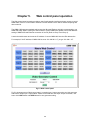
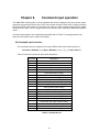
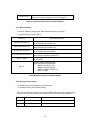
User’s Manual Version 0.9 OMM-1000 Multi-format matrix 16x16 DVI / HDMI / SDI Matrix router TABLE OF CONTENTS Chapter 1. Introduction and installation ................................................................................................ 4 1.1 Key features ............................................................................................................................ 4 1.2 Shipping group ........................................................................................................................ 5 1.3 Notice of safe usage ................................................................................................................ 5 1.4 Physical description ................................................................................................................. 6 1.5 Installation ............................................................................................................................... 7 1.5.1 Initialization ......................................................................................................................... 7 1.5.2 Connection for remote control ............................................................................................ 7 1.6 EDID Configuration.................................................................................................................. 7 Chapter 2. 2.1 Control setup ....................................................................................................................... 9 TCP/IP ..................................................................................................................................... 9 2.1.1 TCP/IP setup of PC ............................................................................................................. 9 2.1.2 Launching Telnet ................................................................................................................ 9 2.2 RS-232 .................................................................................................................................. 10 2.2.1 Launching HyperTerminal ................................................................................................. 10 Chapter 3. Key button operation ......................................................................................................... 11 3.1 LINK mode ............................................................................................................................. 11 3.2 UNLINK mode ....................................................................................................................... 11 3.3 FUNCTION mode .................................................................................................................. 11 3.3.1 Gateway ............................................................................................................................ 12 3.3.2 Subnet Mask ..................................................................................................................... 12 3.3.3 IP Address ........................................................................................................................ 12 3.3.4 MAC Address .................................................................................................................... 13 3.3.5 UDP Port Number ............................................................................................................. 13 3.3.6 Multi Viewer ...................................................................................................................... 14 3.3.7 Video Generator ................................................................................................................ 14 3.3.8 Monitoring Output ............................................................................................................. 15 3.3.9 EDID Configure ................................................................................................................. 15 3.3.10 Baud Rate ......................................................................................................................... 16 2 3.3.11 Control Lock ...................................................................................................................... 17 3.3.12 Reset Mode ....................................................................................................................... 17 Chapter 4. 4.1 PC program operation ................................................................................................. 18 Basic setup ............................................................................................................................ 18 4.1.1 Connect Info ...................................................................................................................... 19 4.1.2 Channel Name .................................................................................................................. 20 4.1.3 Video Generator ................................................................................................................ 20 4.1.4 Control Lock Mode ............................................................................................................ 20 4.1.5 Network ............................................................................................................................. 20 4.2 EDID setup ............................................................................................................................ 20 4.3 Operation ............................................................................................................................... 21 4.3.1 Input / output connection................................................................................................... 22 4.3.2 Input channel status .......................................................................................................... 22 4.3.3 Output channel status ....................................................................................................... 23 4.3.4 Multi-viewer ....................................................................................................................... 23 Chapter 5. Web control panel operation ........................................................................................ 26 Chapter 6. Command input operation ........................................................................................... 27 6.1 Command input structure ...................................................................................................... 27 6.2 Examples of command inputs ............................................................................................... 28 6.2.1 Link input and output ......................................................................................................... 28 6.2.2 Input and output status ..................................................................................................... 28 6.2.3 Network setting ................................................................................................................. 29 6.2.4 Video generator setting ..................................................................................................... 29 6.2.5 Monitor output port setting ................................................................................................ 30 6.2.6 EDID control command ..................................................................................................... 31 6.2.7 Baud rate setting for RS-232 ............................................................................................ 31 6.2.8 Multi-viewer card (QDVI-O) setting ................................................................................... 32 6.2.9 Slot status request ............................................................................................................ 33 6.2.10 Control lock command ...................................................................................................... 33 3 Chapter 1. Introduction and installation The OMM-1000 modular matrix enables to switch up to 16 different DVI / HDMI or SDI sources to 16 different digital displays. It can be configured using 4 input and output cards and each card has 4 ports of input and output. Any input source, whether it is a HD-DVD player, Blue-Ray player or a computer with high-resolution graphics, can be routed to DVI and HDMI output digital display. Note) SDI is not a licensed HDCP interface and if the content received from HDMI is protected by HDCP, there should be no output from the SDI slot. 1.1 Key features ▪ Up to 16 DVI, HDMI and SDI inputs and outputs can be configured. ▪ Each card has 4 input or 4 output ports and 4 cards can be fitted into input and output bays. ▪ Has Electrical DVI, HDMI and SDI and Optical DVI input and output cards. ▪ Any input formats can be converted to DVI, HDMI and SDI. But the resolution between the formats should be same. ▪ Complies with DDC/HDCP (Electrical DVI and HDMI cards only). ▪ Supports up to WUXGA (1920x1200) at 60Hz refresh ratio for DVI or 1080P at 60Hz for HDMI and SDI (Maximum 2.97Gbps bandwidth). ▪ Supports 3 types of EDID management: Default Mode. Auto Mix Mode. Output Copy Mode. ▪ Supports various control methods: Key buttons operation Command input (Such as Hyper terminal by RS-232 and Telnet by TCP/IP) Web panel control (TCP/IP) PC program by RS-232 and UDP ▪ Works with OPTICIS DVI, HDMI and SDI optical extender for long signal extension. ▪ Has dual-power supplier for hot-swappable and load-sharing. ▪ Equips multi-viewer card to be used in various monitoring systems. ▪ Provides diagnostic function for quick trouble shooting. ▪ Has video generator output and monitoring output for easy installation. 4 1.2 Shipping group ▪ OMM-1000, Modular matrix chassis: 1 EA ▪ Input output cards: Option SDVI-4EI, 4 ports electrical DVI input card SDVI-4EO, 4 ports electrical DVI output card SDVI-1FI, 4 ports 1 fiber optical DVI input card SDVI-1FO, 4 ports 1 fiber optical DVI output card HDMI-4EI, 4 ports electrical HDMI input card HDMI-4EI, 4 ports electrical HDMI output card SDI-4EI, 4 ports electrical SDI input card SDI-4EO, 4 ports electrical SDI output card QDVI-O, Multi-viewer card ▪ AC power cord: 1 EA ▪ Power supplier: 1 EA (Dual power supplier is an option) ▪ User manual: 1 EA ▪ Firmware download cable: 1 EA ▪ RS-232 cable (Straight type): 1 EA ▪ PC software CD: 1 EA 1.3 Notice of safe usage We recommend you to read following warning, precaution and information before start to operate the OMM-1000 modular matrix. ▪ Use of the equipment in a manner not specified by the manufacturer may result in irecoverable damage. ▪ Keep the unit away from liquid, magnetic and combustible substances. ▪ Do not place heavy weight on the unit. ▪ Move away from noisy environment such as vibration or impact. ▪ Do not install the unit vertically. ▪ Do not disassemble the unit. 5 1.4 Physical description The OMM-1000 modular matrix chassis is mountable on a 19” standard rack. Key buttons, LCD display and reset switch are placed on the front panel as shown in Figure 1-1. Figure 1-1 Front panel of OMM-1000 All Input and output cards, interface ports and power supplier are placed on the rear panel as below. ▪ Input bay for 4 input cards (left side) ▪ Output bay for 4 output cards (right side) ▪ SERVICE, RJ-11 receptacle for firmware upgrade ▪ RS-232, Serial communication port ▪ LAN, RS-45 receptacle for TCP/IP or UDP control ▪ REFERENCE OUTPUT for internal video source for easy installation ▪ MONITORING OUTPUT for internal output port to monitor input signal ▪ Power supplier (Dual-power is an option) Figure 1-2 Rear panel of OMM-1000 6 1.5 Installation 1.5.1 Initialization ▪ Connect the provided AC power cord to AC power inlet and turn on switch on the front panel. Then, OMM-1000 will start initialization process (To turn it off completely, pull out AC power cord, switch on the front panel is rest switch). ▪ ‘OMM-1000 Starting’ will be shown on LCD display. ▪ After 7~10 sec, ‘OMM-1000 Booting complete’ message and hardware and firmware version information will be shown. ▪ Now, OMM-1000 is ready to receive commands from user. 1.5.2 Connection for remote control ▪ Connect the OMM-1000 to PC with the supplied RS-232 cable. ▪ Connect the OMM-1000 to PC with LAN cable with RJ-45 connector. [NOTE] Typically, the IP address of PC connected to the network is configured by DHCP server. But, if the PC is connected directly to the OMM-1000, the network server will not able to assign the IP address. In this case, network information of PC should be set manually. The default IP address of OMM-1000 is 192.168.1.117. Before connecting OMM1000 to your network, please verify the availability of IP address in your network. The IP address can be reconfigured by key button, PC program or command lines over RS-232 or TCP/IP. 1.6 EDID Configuration ▪ EDID (Extended Display Identification Data) is an information set that is provided by a display to describe its capabilities to a graphic source. It enables a graphic source to identify the connected display. ▪ The information set includes: manufacturer, product type, phosphor or filter type, timings supported by the display, display size, luminance data and (for digital displays only) pixel mapping data. ▪ Once the graphic source reads the information set (usually during the booting process), the EDID determines the optimal format for a connected display. ▪ OMM1000 supports storing of EDID information to an EEPROM for each Input. ▪ OMM1000 has three-way EDID settings, 1) Default Mode: default EDID from the factory, 2) Output Copy Mode: read of EDID from any target display and copy in input port and the most 7 advanced one is 3) Auto Mix Mode: analyzing of all EDID from the attached displays and store optimized EDID in input port to avoid any compliance problems in the field. Displays OUTPUT 1~16 Sources INPUT 1~16 WRITE EDID EEPROM1 EDID EEPROM2 INTERFACE CONTROL EEPROM3 Read/Write . . . . . . . . EEPROM16 Figure 1-3 Concept of EDID setting and working in OMM-1000 modular matrix As depicted in Figure 1-3, once EDID is configured, each EDID is stored in EEPROM in Input ports. As a result, the video sources are able to read EDID from the EEPROM during booting process even though the OMM-1000 and connected displays are not powered on yet. 8 Chapter 2. Control setup The OMM-1000 modular matrix can be controlled in various ways such as command input (RS-232, TCP/IP), Web control panel (TCP/IP), supplied PC program (RS-232, UDP) as well as key button on the front panel. To do this, PC should be configured properly. 2.1 TCP/IP 2.1.1 TCP/IP setup of PC TCP/IP, the abbreviation of Transmission Control Protocol (TCP) and the Internet Protocol (IP) is commonly used protocol to control remote computers. To control OMM-1000 over TCP/IP, set network properties of PC as below (Explained here is based on Win 7 OS). ▪ Open Control Panel. ▪ Select Network Status in Network and Internet menu. ▪ Select Adapter setting. ▪ Select Local Area Connection and right click to open property. ▪ Select Internet Protocol Version 4 (TCP/IPv4) ▪ Enter IP, Subnet mask, Gateway and DNS server address, compatible with the current network setting of OMM-1000. ▪ Click OK to terminate IP setup session. [Note] If the IP address of OMM-1000 is 192.168.001.117, the PC IP address should be chosen as 192.168.001.nnn; where ‘nnn’ can range from 000 to 255 except 117. 2.1.2 Launching Telnet Telnet is a terminal program embedded in Window OS system to access remote computers using TCP/IP protocol. With the network setting of the PC as above, launch Telnet as below. ▪ Make sure PC and OMM-1000 are connected by Ethernet. ▪ Click Start menu and select Run. ▪ Type CMD to open command widow. ▪ Type ‘telnet 192.168.1.117’ (Type current IP address of OMM-1000). 9 ▪ Press ENTER then, “==Welcome to OMM-1000==” and “== TELNET control ==” messages will be shown. ▪ Type command inputs to control OMM-1000. (Refer to Chap. 5) 2.2 RS-232 2.2.1 Launching HyperTerminal The OMM-1000 modular matrix provides RS-232 serial communication. The simplest way to control OMM-1000 over RS-232 is using embedded software in Windows OS, HyperTerminal. To launch Hyper Terminal (Explained here is based on Windows XP OS. Hyper Terminal is not available on Win 7.): ▪ Connect the PC to OMM-1000 over RS-232 cable. ▪ Select Start > Programs > Accessories > Communications > HyperTerminal. ▪ Enter a name and choose an icon in Connection Description window and click OK. ▪ In Connect To window, ignore the Country, Area Code and Phone Number fields but select available COM port of PC to be connected to OMM-1000 then, click OK. ▪ In COM Properties window, set the parameters as below: Bits per second (baud rate): 115200 (115200 is default baud rate of OMM-1000) Data bits: 8 Parity: None Stop bits: 1 Flow control: None [Note] Bit per second of Hyper Terminal should be set as same as baud rate of OMM-1000. ▪ Click OK to save the parameters. ▪ Go Start > Programs > Accessories > Communications > HyperTerminal, then new icon will be shown. Then select it to launch Hyper Terminal. ▪ Type command inputs to control OMM-1000 (Refer to Chap. 5) 10 Chapter 3. Key button operation 3.1 LINK mode ▪ It configures input / output connections for cross-switching. 1) Press LINK key button. 2) Press an input key button - LCD will display current connected output. 3) Press single or multiple output key buttons to select desired outputs. 4) Outputs can be deselected by pressing the each output key button again. 5) Press ENTER key button to save the configuration. 6) To configure next Input / output connection, repeat steps 1 to 5. 3.2 UNLINK mode ▪ It unlinks input /output connection. 1) Press SHIFT key button. 2) Press LINK key button. 3) Press the input key button to be disconnected. 4) Press ENTER key button. 3.3 FUNCTION mode ▪ It configures basic setting of OMM-1000 to be controlled by command input and PC program. ▪ Press FUNCTION to see features – FUNCTION key button will cycle the following features repeatedly: Gateway Subnet Mask IP Address Mac Address UDP Port Number Multi-viewer (It is activated when QDVI-O is in output bay) Video Generator Monitoring Output EDID Configure Baud Rate Control Lock Reset Mode 11 3.3.1 Gateway: Press FUNCTION key button once ▪ The cursor shows that it is selected and activated. ▪ Input 3 key button decreases the number. ▪ Input 4 key button increases the number. ▪ Input 1 and 2 key buttons move the cursor left and right. ======Gate Way====== O: 192. 168. 001. 001 N: 192. 168. 001. 001 ▪ Modify the Gate way address to be used for your network. ▪ Press ENTER key button to complete the process. ▪ The default setting is 192.168.001,001 3.3.2 Subnet Mask: Press FUNCTION key button two times ▪ The cursor shows that it is selected and activated. ▪ Input 3 key button decreases the number. ▪ Input 4 key button increases the number. ▪ Input 1 and 2 key buttons move the cursor left and right. ====Subnet Mask==== O: 255. 255. 255. 000 N: 255. 255. 255. 000 ▪ Modify the Subnet mask address to be used for your network. ▪ Press ENTER key button to complete the process. ▪ The default setting is 255.255.255.000. 3.3.3 IP Address: Press FUNCTION key button three times ▪ The cursor shows that it is selected and activated. ▪ Input 3 key button decreases the number. ▪ Input 4 key button increases the number. ▪ Input 1 and 2 key buttons move the cursor left and right. =====IP Address===== O: 192. 168. 001. 117 N: 192. 168. 001. 117 12 ▪ Modify the IP address to be used for your network. ▪ Press ENTER key button to complete the process. ▪ The default setting is 192.168.001.117. 3.3.4 MAC Address: Press FUNCTION key button four times ▪ The cursor shows that it is selected and activated. ▪ Input 3 key button decreases the number. ▪ Input 4 key button increases the number. ▪ Input 1 and 2 key buttons move the cursor left and right. =====MAC Address==== O: 00.11.AA.EE.DD.FF N: 00.11.AA.EE.DD.FF ▪ Modify the MAC address to be used for your network. ▪ Press ENTER key button to complete the process. 3.3.5 UDP Port Number: Press FUNCTION key button five times ▪ It makes number setting, data range from 0 to 65535. ▪ The cursor shows that it is selected and activated. ▪ Input 3 key button decreases the number. ▪ Input 4 key button increases the number. ▪ Input 1 and 2 key buttons move the cursor left and right. =========Function Mode======== Port Number Old data: 03000 New data: 03000 ▪ Modify the UDP port number to be used for your network. ▪ Press ENTER key button to complete the process. ▪ The default UDP port number is 03000. [Note] Port number setting in this section is used for UDP with supplied PC program not TCP/IP with web browser or Telnet. For TCP/IP, port number 23 is fixed value. 13 3.3.6 Multi Viewer: Press FUNCTION key button six times ▪ Multi-viewer card, QDVI-O can choose 4 inputs among 16 inputs of OMM-1000 and configure and output these input signals with 7 different layouts. For more details, refer to chap. 4.3.4. ▪ The cursor shows that it is selected and activated. ▪ Input 1 and 2 key buttons move the menu. ▪ Input 3 key button decreases the number. ▪ Input 4 key button increases the number. ====Multi Viewer==== SLOT No.: 01 Resol: 01 800x600 Layer: Layer 01 1) Select the SLOT No. by pressing input 3 or 4 key button and select slot number where QDVI-O is inserted by pressing input 1 or 2 key button. 2) Select the output resolution. 3) Select Layout. 4) Press ENTER key button to complete the process. 3.3.7 Video Generator: Press FUNCTION key button seven times ▪ It changes resolution and pattern of video generator. ▪ The cursor shows that it is selected and activated. ▪ Input 1 and 2 key buttons move the menu. ▪ Input 3 key button decreases the number. ▪ Input 4 key button increases the number. ==Video Generator== Resol: 01 800x600 Image: 01 V Bar Stop OSD: ON 1) Select the resolution, pattern and OSD by pressing the key buttons as guided above. 2) Press ENTER key button to complete the process. [Note] OSD shows the resolution and pattern information on the top left of the display. 14 3.3.8 Monitoring Output: Press FUNCTION key button eight times ▪ It allocates input to Monitor Output port for monitoring uses. ▪ The cursor shows that it is selected and activated. ▪ Input 3 key button decreases the number. ▪ Input 4 key button increases the number. =Monitoring Output= Old Input: 01 New Input: 01 1) Connect a display to the Monitoring Output port and any video sources to the DVI input ports on the real panel. 2) Select an input port by pressing input 3 or 4 key button. 3) Press ENTER key button to complete the process. 3.3.9 EDID Configure: Press FUNCTION key button nine times ▪ It sets EDID information in input port. ▪ OMM-1000 supports three types of EDID setting: Default Mode, Auto Mix Mode and Output Copy Mode. For more information, refer to Chap. 5.2. ▪ The cursor shows that it is selected and activated. ▪ Input 1 and 2 key buttons select YES and NO. ▪ Input 3 and 4 key buttons move left and right (Change EDID mode). ▪ Input 5 and 6 key buttons move down and up (Decrease and increase the port number). ===EDID Configure=== Entry EDID Configure? _1: Entry 1) Press input 1 key button to enter the EDID Configure Mode. ===EDID Configure=== Input: 01 Default Default Mode? 1: Y 2: N 3: << 4: >> 5: ∨ 6: ∧ [Note] The EDID configuration that is shown next to the input number on the LCD display is current EDID mode 2) Select an input port by pressing input 5 or 6 key button. 3) Press input 3 or 4 key button to change EDID mode. 15 3-1) If you select Default Mode, default EDID will be restored for allocated inputs. ===EDID Configure=== Input: 01 Default Default Mode? 1: Y 2: N 3: << 4: >> 5: ∨ 6: ∧ Press input 1 key button then, the OMM-1000 will recover the Default EDID to allocated input as below. ===EDID Configure=== EDID Copying…. EDID Reading…. 3-2) If you select Auto Mix Mode, mixed EDID of all attached displays will be saved in allocated input. 3-3) If you select Output Copy Mode, OMM-1000 reads EDID from any target displays and copies it in allocated input. [Note] There is Edit Data Mode but it is used to modify existing EDID to make new EDID working with specific systems. It is not recommended for general user. For further information, please contact [email protected] 3.3.10 Baud Rate: Press FUNCTION key button ten times ▪ It sets RS-232 Baud Rate. OMM-1000 supports 9600, 19200, 38400, 57600, 115200bps. =====Baud rate===== Old baud: 115200 New baud: 115200 ▪ Input 3 key button decreases the number. ▪ Input 4 key button increases the number. ▪ Press ENTER key button to complete the process. ▪ The default setting is 115200 16 3.3.11 Control Lock: Press FUNCTION key button eleven times ▪ It locks and unlocks the controls such as Web, RS-232, TCP/IP, UDP and key Button ====Control Lock==== Web Lock? UnLock Data Lock? UnLock Key Lock? UnLock ▪ Input 1 and 2 key buttons move the cursor up and down. ▪ Input 3 key button moves Lock. ▪ Input 4 key button moves UnLock. ▪ Press ENTER key button to complete the process. 3.3.12 Reset Mode: Press FUNCTION key button twelve times ▪ It resets OMM-1000. It starts rebooting and restores all default setting. ▪ Input 1 and 2 key buttons select YES and NO. ▪ Press ENTER key button to complete the process. 17 Chapter 4. PC program operation The PC program and provides a user-friendly graphic interface alternative to key button input and command input operation. Copy OMM ver1.x.exe file in any directories in your PC and double click it to run. Then, initial window of PC program for OMM-1000 as below will open. Fig 4-1 PC program of OMM-1000 4.1 Basic setup Click Set Config button to set the communication method, input output name, Video generator and so on. Then, the Set Config window as below will open. 18 Fig 4-2 Set Config window of OMM-1000 PC program 4.1.1 Connect Info ▪ Select the way of control method between RS-232 and Ethernet (UDP) by click the radio buttons. ▪ In case of RS-232 control, enter available COM port number of your PC and select baud rate. The baud rate should be same as that OMM-1000. (115200 is default) ▪ In case of Ethernet, enter IP address of OMM-1000 and port number. 3000 is default port number of OMM-1000. ▪ Click save button and close Set Config window then click Connect button on PC program of OMM-1000 to start it. ▪ If the connection is properly made, current status of OMM-1000 will be shown at the bottom side of PC program. 19 4.1.2 Channel Name ▪ User can allocate specific names for all inputs and outputs to distinguish them ▪ On Fig 4.2, The name of Camera #1 was assigned for Input CH05 and Wall display #3 for output CH07. ▪ Click Save button to save it then, these will be applied on the PC program as shown in Fig 4-1. 4.1.3 Video Generator ▪ Select the resolution and pattern of video generator. ▪ Click Apply button to save it. 4.1.4 Control Lock Mode ▪ It locks and unlocks the controls such as Web, Data control (RS-232, TCP/IP and UDP) and key button input. ▪ Click Apply button to save it. 4.1.5 Network ▪ It changes network information of OMM-1000. ▪ Click Apply button to save it. 4.2 EDID setup OMM-1000 offers 3 types of EDID setting for easy installation with various displays in the market. To set the EDID option for each input port, click Set EDID button then, Setup EDID window as below will open. Fig 4-3 Setup EDID window of OMM-1000 PC program 20 To set EDID information for each input select mode button and click input channel. For each mode, multi-input channels can be allocated. ▪ Default mode is default EDID from the factory. By selecting it, default EDID will be recovered for allocated input channels. ▪ Auto Mix mode is the most advanced one it analyzes all EDID of attached displays at the output ports of OMM-1000 and get optimized EDID. By selecting it, user can avoid any compliance problems in the field. ▪ Output Copy mode is most popular one. It reads EDID from any target displays and copies it in input port. Select output channel first and click input channels. And click Apply button to save it. There is User’s Edit mode but it is used to modify existing EDID to make new EDID working with specific systems. It is not recommended for general user. For further information, please contact [email protected] 4.3 Operation And all of setting parameters will be shown on the right side of PC program as Fig 4-3. After clicking Connect button (Refer to Chap. 4.1.1), OMM-1000 is ready to get the command from user. Fig 4-4 Setting parameters of OMM-1000 21 The right side of PC program shows various connection status such as input / output connections, Input signal resolution and status, EDID setting for each input and Input / output card information and used to make new input / output connections too. Fig 4-5 Input and output status of OMM-1000 4.3.1 Input / output connection ▪ Click one of input channels and click any of output channels. If you click input CH05 (Camera #1) and click output CH05, CH06, CH07 and CH06 input signal 05 will be connected to output monitor 05, 06, 07 and 08 as shown in Fig 4-5. ▪ To connect one input to all output, click All Link button and click desired input. Then all of output will be connected to it. ▪ To disconnect all outputs, click Link Clear button. 4.3.2 Input channel status ▪ Green LEDs above input channel number such as CH05 and CH10 are signal detection from source. It means only CH05 and CH10 are connected with video sources. ▪ If the green LED lit ON, user can recognize the resolution of input signal (ex. 22 CH05=1920x1080p). ▪ If LED OFF, sources are not connected and it shows ‘Signal OFF’. ▪ DEF., AUTO, OUT. and USER, right side of input channel number are EDID mode that is allocated for each input (Refer to Chap. 4.2) ▪ There are 4 slots for input cards and OMM-1000 recognizes its type during booting process and shows it on PC program when it launched. (Ex. Slot 1 is fiber optic input card, SDVI-1FI and Slot 2 is electrical DVI input card, SDVI-4EI) 4.3.3 Output channel status ▪ Green LEDs above output channel number such as CH07 is Hot Plug Detection (HPD) from display. It means CH07 is connected with display. ▪ But in case of fiber optic card (slot 1), multi-viewer card (slot 4) and SDI output channel LEDs are lit ON regardless of HPD. ▪ The connected outputs show input source information (ex. CH07=Camera #1, input CH05). ▪ The disconnected outputs show ‘No Link’. ▪ There are 4 slots for output cards and OMM-1000 recognizes its type during booting process and shows it on PC program when it launched. (Ex. Slot 1 is fiber optic output card, SDVI-1F0 and Slot 2 is electrical DVI output card, SDVI-4EO) 4.3.4 Multi-viewer ▪ The most outstanding feature of OMM-1000 is embedded multi-viewer card, QDVI-O. ▪ Multi-viewer card, QDVI-O can choose 4 inputs among 16 inputs of OMM-1000 and configure and output these input signals with 7 different layouts. 1st input 2nd input st nd [1 layout] 1st input 4th input rd [2 layout] th [3 layout] [4 layout] 2nd 2nd input 1st input st 1 input 3rd input 3rd input input 4th input rd 3 4th 2nd th th 4th th [6 layout] [5 layout] 3rd [7 layout] Fig 4-6 Layouts of Multi-viewer st st 1 layout: Select 1 input of QDVI-O and output it on a full screen nd nd 2 layout: Select 2 input of QDVI-O and output it on a full screen 23 rd rd 3 layout: Select 3 input of QDVI-O and output it on a full screen th th 4 layout: Select 4 input of QDVI-O and output it on a full screen th 5 layout: Make quad-view of 4 inputs (same size) th st th st 6 layout: Set 1 input on the left side and other 3 on the right side 7 layout: Set 1 input on the top side and other 3 on the bottom side ▪ QDVI-O can be inserted one of output slots and it will be shown on PC program as in Fig 4-5 (Out slot 4). ▪ Click OUT SLOT 4 bar to launch Setup Quad Multiviewer Card window as shown in Fig 47. ▪ Select output resolution of multi-viewer card first. ▪ Select output layout. Fig 4-7 Multi-viewer card setup [Note] 1. Changing the output resolution and layout of multi-viewer card, QDVI-O can be done by PC program and command input and key button operation. 2. To change position of window in layout 5, 6 and 7, user must change the order of input to QDVI-O. For example, If the QDVI-O is in output slot 2, to change window position of layout 5 as shown in Fig 4-8, user must change input output connection. 24 A C B D Change Input / output connection of OMM-1000 C B A D Fig 4-8 Changing widow position of layout st In Fig 4-8, Video source A is output 5 of OMM-1000 and it is also the 1 input to QDVI-O rd and source C is output 7 of OMM-1000 and the 3 input of QDVI-O. To change A and C, user makes source A be connected to output 7 of OMM-1000 (It will be the 3rd input of QDVI-O) then, source A will be shown on the bottom left side of layout 5. As the same method, if user allocate source C to output 5 of OMM-1000, it will be shown on the top left side. 3. Scale-down error will happen when the number of scale-down vertical pixels are less than 1/5 (Progressive input case) or 1/4 (Interlaced input case) of original input vertical pixels. For example, in case of layout 6, if you use input resolution, 1280x1024 st and set the output resolution of QDVI-O at 800x600, the number of vertical pixels of 1 nd rd 2 and 3 inputs will be fitted into one third of output vertical pixels (600). In this case, there would be an error because the number of scale-down vertical pixels, 200 (600/3) is less than 204.8 (1024/5). 25 Chapter 5. Web control panel operation The Web control panel operation provides a user-friendly graphic interface and easy access to control OMM-1000, if the PC is connected to Ethernet. But the functions are a little bit limited comparing with other methods. The OMM-1000 supports standard web browser but Microsoft Explorer is highly recommended to run OMM-100 stably. Before running the web browser to control OMM-1000, please confirm that Network setting of OMM-1000 and Ethernet connection of the PC (Refer to Chap 2 and Chap 3). Launch the web browser and enter the IP address of current OMM-1000 into the URL address line. For example, if the IP address of OMM-1000 is set as 192.168.001.117, jut type 192.168.1.117. Fig 5-1 Web control panel Fig 5-1 shows structure of Web control panel. It controls input / output connection and vide generator and informs simple input / output status. Please remind that after new input /output connection, user has to click LINK button and SEND button for new generator setting. 26 Chapter 6. Command input operation The OMM-1000 modular matrix could be operated with various interfaces such as key button inputs, command input through RS-232 and TCP/IP, Web control through TCP/IP and PC program through RS-232 and UDP. All functions are executed on a basis of a serial command input, but the graphic interfaces on the Web or the PC program make more efficient way to operate the OMM-1000 modular matrix. Command input operation is accomplished through RS-232 or TCP/IP. For setting procedures for those protocols, please refer to Chap 2 and Chap 3. 4.4 Command input structure The command inputs are composed of a string of ASCII codes and its basic structure is; Command + Delimiter (‘=’) + Data + Delimiter (‘^’ or ‘,’ or ‘_’) + Data + End (‘!’) Table 6.1 shows all commands and its brief descriptions Command Description LINK Input and Output connection IN Input signal status request OUT Output signal status request NET Network information request NETGW Gateway address setting NETSN Subnet mask address setting NETIP IP address setting NETPA MAC address setting NETPT UDP port number setting VID Video generator status request VIDRES Video generator resolution setting VIDIMG Video generator pattern setting MON Monitoring port setting and status request EDID EDID mode setting EDIT Edited EDID transferring RS232 RS-232 Baud rate setting QUAD Quad-viewer card status request QUADRES Quad-viewer card output resolution setting QUADLAY Quad-viewer card layout setting SLOT Input output slot status request LOCK Lock/Unlock the control type Table 6.1 Commands set 27 ▪ The command input allows executing only one command. Multiple command inputs require executing multiple strings having each command per a string. ▪ User can use capital letters and small letters for commands but cannot mix it like ‘Link’, it must be corrected as ‘link’ or ‘LINK’. ▪ After all input commands, OMM-1000 sends back replies to conform the execution of commands. ▪ Input and output port number range from 1 to 16 and prefix, ‘0’ can be used such as ‘001’ and ‘010, but in the replies after the command inputs, the digits of port number are two such as ‘01’ and ‘10’. 4.5 Examples of command inputs 4.5.1 Link input and output ▪ It makes single or multi-connections of inputs and outputs. ▪ It makes disconnection of all inputs when used with ‘0’. ▪ It requests inputs and outputs status of OMM-1000. Command LINK=01^10! LINK =1^03,04^7! Description and reply Makes input 1 connected to output 10. Reply: LINK=01^10! Makes input 1 connected to output 3 and 4 to 7. Reply: LINK =01^03,04^07! LINK =05! Makes input 5 connected to all outputs. Reply: LINK=05! LINK =00! Makes all connections disconnected. Reply: LINK =00! LINK =00^06! Link=?! Makes output 6 disconnected. Reply: LINK =00^06! Requests current inputs and outputs connections status. Reply: LINK =01^01,02^04,~16^13! Table 6.2 Link command examples 4.5.2 Input and output status ▪ It requests input signal status. If the input is connected, it replies input resolution, but if it is not connected, it returns ‘Signal Off’. ▪ It requests output status whether it is connected to display or not. Command IN=05! Description and reply Requests input 5 status. Reply: IN=[05] 1920x1200p! or IN=[05] Signal Off! 28 Requests output 12 status. Reply: OUT=[12] Un Plugged! or OUT=[12] Plugged! OUTPUT=12! Table 6.3 Input and output status command examples 4.5.3 Network setting ▪ It sets IP, Gateway, Subnet mask, MAC address and UDP port number. ▪ It requests current network setting. Command Description and reply NETGW=192.168.1.1! NETIP=192.168.1.118! NETSN=255.255.255.0! Sets Gateway address, each data ranges from 000 to 255. Reply: NETGW=192.168.001.001! Sets IP address, each data ranges from 000 to 255. Reply: NETGW=192.168.001.118! Sets Subnet mask address, each data ranges from 000 to 255. Reply: NETSN=255.255.255.000! NETPA=AA.BB.CC.DD.EE.FF! Sets MAC address, each data ranges from 00 to FF. Reply: NETPA= AA.BB.CC.DD.EE.FF! NETPT=3000! Sets UDP port number, data ranges from 0 to 65535. NETPT=3000! NET=?! Requests current network setting. Reply: NETGW=192.168.001.001! NETIP=192.168.001.118! NETSN=255.255.255.000! NETPA=AA.BB.CC.DD.EE.FF! NETPT=3000! Table 6.4 Network setting command examples 4.5.4 Video generator setting ▪ It changes resolution and pattern of video generator. ▪ It requests current video generator setting. Table 6.5 describes the resolutions and patterns OMM-1000 supports. By command input operation, user can change these to be used with on-site source for easy installation Data # Resolution Pattern 1 800x600@60Hz Vertical Color Bar 2 1024x768@60Hz Vertical Color Bar scroll (Interval:0.5sec) 29 3 1280x960@60Hz Vertical Color Bar scroll (Interval:1.0sec) 4 1280x1024@60Hz Horizontal Color Bar 5 1600x1200@60Hz Horizontal Color Bar scroll (Interval:0.5sec) 6 1920x1200@60Hz Horizontal Color Bar scroll (Interval:1.0sec) 7 1280x720p@60Hz Full White 8 1920x1080i@60Hz Full Yellow 9 1920x1080p@60Hz Full Cyan 10 Full Green 11 Full Magenta 12 Full Red 13 Full Blue 14 Full Gray Table 6.5 Video generator resolutions and patterns Command Description and reply VIDRES=4! Sets video generator resolution by data #4. Reply: VIDRES=1280x1024@60HZ! VIDIMG=3! Sets video generator pattern by data #3. Reply: VIDIMG=VCOLORBAR10SMOVE! VID=?! Requests current video generator resolution and pattern. Reply: VID=04_03! (it means data #4 resolution and data #3 pattern) Table 6.6 Video generator command examples 4.5.5 Monitor output port setting ▪ It makes input to connected to monitor output port. ▪ It requests current input port that connected to monitor output port. Command Description and reply MON=13! Makes input 13 connected to monitor output ports. Reply: MON=13! MON=?! Requests current input port that connected to monitor output port. Reply: MON=13! Table 6.7 Monitor output setting command examples 30 4.5.6 EDID control command ▪ It stores EDID information in input port of OMM-1000. ▪ It requests current EDID setting for all input ports. Command Description and reply Default mode: Saves default EDID in input ports 1, 7 and 15. Reply: EDID=01DEF.! EDID=07DEF.! EDID=15DEF.! EDID=DE1,7,15! EDID=AUTO2,8,9! Auto mix mode: Analyzes all EDID information of connected displays to makes optimized EDID then save it in input ports 2, 8 and 9. Reply: EDID=02AUTO! EDID=08AUTO! EDID=09AUTO! EDID=OUT3_5! Output copy mode: Copies EDID information of output 3 display and stores it in input port 5. Reply: EDID=03OUT.! Requests current EDID setting for all inputs. Reply: EDID=01OUT.02AUTO03OUT.~16EDF.! EDID=?! Table 6.8 Monitor output setting command examples 4.5.7 Baud rate setting for RS-232 ▪ It sets RS-232 baud rate. OMM-1000 supports 9600, 19200, 38400, 57600, 115200bps. ▪ It requests current RS-232 baud rate. Command Description and reply RS232=115200! Sets RS-232 baud rate. Reply: RS232=115200BPS! RS232=?! Requests current baud rate. Reply: RS232=115200BPS! Table 6.9 Baud rate setting command examples 31 4.5.8 Multi-viewer card (QDVI-O) setting ▪ It sets output resolution and layout of QDVI-O. ▪ It requests current status of QDVI-O. Data # Resolution Layout 1 800x600@60Hz 1 input of QDVI-O on a full screen 2 1024x768@60Hz 2 input of QDVI-O on a full screen 3 1280x960@60Hz 3 input of QDVI-O on a full screen 4 1280x1024@60Hz 4 input of QDVI-O on a full screen 5 1600x1200@60Hz Quad-screen 6 1920x1200@60Hz 1 Large screen (Left side) + 3 Small screen (Right side) 7 1280x720p@60Hz 1 Large screen (Top side) + 3 small screen (Bottom side) 8 - - 9 1920x1080p@60Hz - st nd rd th Table 6.10 Supporting resolutions and layouts of QDVI-O The first numeric data in command line represents slot number of output bay of OMM-1000 where QDVI-O is inserted. Command Description and reply QUADRES=3_9! Sets output resolution of QDVI-O at 1920x1080P. In this case, rd QDVI-O is inserted in 3 slot of output bay. Reply: QUADRES=03_09! QUADLAY=1_5! Sets layout of QDVI-O as quad-screen. In this case, QDVI-O is st inserted in 1 slot of output bay. Reply: QUADLAY=01_05! QUAD=?! Request current status of QDVI-O. If one QDVI-O is inserted in 2 slot and output resolution is 1600x1200@60Hz with layout #6: Reply: QUAD=01_00_00,02_05_06,03_00_00,04_00_00! Table 6.11 Multi-viewer card setting command examples 32 nd 4.5.9 Slot status request ▪ It requests current cards type in input and output bay. Data Card type Data Card type 02 Single DVI input card, SDVI-4EI 12 SDI input card, SDI-4EI 03 Single DVI output card, SDVI-4EO 13 SDI output card, SDI-4EO 18 1 Fiber DVI input card, SDVI-IFI 06 Reserved 19 1 Fiber DVI output card, SDVI-1FO 07 Reserved 21 Multi-viewer card, QDVI-O 1A Reserved 0A HDMI input card, HDMI-4EI 1B Reserved 0B HDMI output card, HDMI-4EO - Table 6.12 Card types and its data The first numeric data in reply represents the order row of slot and second and third data represents type of input and output cards. Command SLOT=?! Description and reply Requests current cards type in input and output bay. OMM-1000 has 4 rows of input and output slots. If the input output cards are configured as below: st 1 row: Single DVI input card / 1 Fiber DVI output card nd 2 row: Single DVI input card / Multi-viewer card rd 3 row: 1 Fiber DVI input card / Single DVI output card th 4 row: 1 Fiber DVI input card / NO output card Reply: SLOT=01_02_19! SLOT=02_02_21! SLOT=03_18_03! SLOT=04_18_00! Table 6.13 Slot status request command example 4.5.10 Control lock command ▪ It locks and unlocks the controls such as Web, RS-232, TCP/IP and UDP. ▪ It request open status of controls. 33 ASCII Description WL Web control lock WUL Web control unlock DL Data control (UDP, TCP/IP, RS-232) lock DUL Data control (UDP, TCP/IP, RS-232) unlock KL Key control lock KUL Key control unlock Table 6.14 Locking type and its ASCII data Command LOCK=DL! LOCK=?! Description and reply Locks data control. Reply: LOCK=DL! Request current status of control method. Reply: LOCK=WUL,DUL,KUL! Table 6.15 Control lock command examples 34 Opticis Locations Opticis Co., Ltd. #907 Byucksan Technopia, 434-6, Sangdaewon-Dong, Chungwon-Ku, Sungnam City, Kyungki-Do, 462-120, South Korea Tel: +82 (31) 737-8033 Fax: +82 (31) 737-8079 For order support, please contact your Distributor or Reseller. For technical support, visit Opticis web site, www.opticis.com or contact [email protected] 35