1
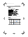
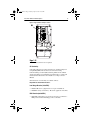
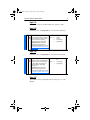
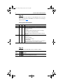
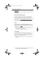
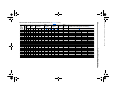
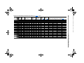
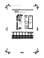
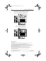
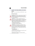
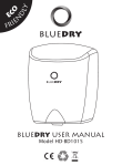
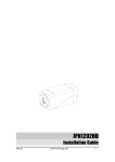
20b_du1b.fm Page 1 Tuesday, April 23, 2002 11:00 AM
Document Update
PowerFlex 700 User Manual Updates
This document contains updated information for the PowerFlex 700
User Manual (publication 20B-UM001A-EN-P) dated April, 2001. This
document supersedes any previous updates for the PowerFlex 700 User
Manual.
Page 1-6
A new section has been added for Frame 5 drives.
!
ATTENTION: To avoid a shock hazard, assure that all power to the
drive has been removed before performing the following.
AC Input Phase Selection (Frame 5 Only)
Moving the “Line Type” jumper as shown in the figure below will select
single or three-phase operation.
Selecting/Verifying Fan Voltage (Frame 5 Only)
Frame 5 drives utilize a transformer to match the input line voltage to the
internal fan voltage. If your line voltage is different than the voltage
class specified on the drive nameplate, it may be necessary to change
transformer tap as shown below.
Sin
gle
-Ph
as
Th
e
ree
(de -Ph
fau ase
lt)
Phase Selection
Jumper
Line Type
➋
Spare
Optional
Communications
Module
Spare
Fan Voltage
300 VDC EXT PWR SPLY TERM (PS+, PS-)
POWER TERMINAL RATINGS
WIRE RANGE: 14-1/0 AWG (2.5-35 MM2)
TORQUE: 32 IN-LB (3.6 N-M)
STRIP LENGTH: 0.67 IN (17 MM)
USE 75° C CU WIRE ONLY
GROUND TERMINAL RATINGS (PE)
WIRE RANGE: 6-1/0 AWG (16-35 MM2)
TORQUE: 44 IN-LB (5 N-M)
STRIP LENGTH: 0.83 IN (21 MM)
WIRE RANGE: 22-10 AWG (0.5-4 MM2)
TORQUE: 5.3 IN-LB (0.6 N-M)
STRIP LENGTH: 0.35 IN (9 MM)
17
9
21
OUTPUT
INPUT AC
➌
690 Volt Tap
600 Volt Tap
480 Volt Tap
400 Volt Tap
➊
x4
File Name: AB_PowerFlexACDrive_700_userupdate_D302
20b_du1b.fm Page 2 Tuesday, April 23, 2002 11:00 AM
2
PowerFlex 700 User Manual Updates
Page 1-7
Table was updated to include Frame 5 information. Frame 5 terminals
are identified on pages 1 and 3.
Table 1.B Power Terminal Block Specifications
Wire Size Range (1)
No. Name
Frame Description
Maximum Minimum
➊ Power Terminal 0 & 1 Input power and 4.0 mm2 0.5 mm2
Block
motor connections (10 AWG) (22 AWG)
2
Input power and 10.0 mm2 0.8 mm2
motor connections (6 AWG) (18 AWG)
3
Input power and 25.0 mm2 2.5 mm2
motor connections (3 AWG) (14 AWG)
BR1, 2 terminals 10.0 mm2 0.8 mm2
(6 AWG) (18 AWG)
5
Input power, BR1, 35.0 mm2 2.5 mm2
(75 HP) 2, DC+, DC– and (1/0 AWG) (14 AWG)
motor connections
PE
35.0 mm2 16.0 mm2
(1/0 AWG) (6 AWG)
5
Input power, DC+, 70.0 mm2 16.0 mm2
(100 HP) DC– and motor (3/0 AWG) (4 AWG)
connections
BR1, 2, terminals 35.0 mm2 2.5 mm2
(1/0 AWG) (14 AWG)
PE
35.0 mm2 16.0 mm2
(1/0 AWG) (6 AWG)
Torque
Maximum
1.7 N-m
(15 lb.-in.)
1.7 N-m
(15 lb.-in.)
3.6 N-m
(32 lb.-in.)
1.7 N-m
(15 lb.-in.)
3.6 N-m
(32 lb.-in.)
➋
SHLD Terminal 0-5
Terminating point
for wiring shields
—
1.6 N-m 1.6 N-m
(14 lb.-in.) (14 lb.-in.)
➌
AUX Terminal
Block
Auxiliary Control
Voltage (2)
1.3 mm2
(16 AWG)
4.0 mm2
(10 AWG)
0-3
5
(1)
(2)
—
Recommended
0.8 N-m
(7 lb.-in.)
1.4 N-m
(12 lb.-in.)
1.8 N-m
(16 lb.-in.)
1.4 N-m
(12 lb.-in.)
3.6 N-m
(32 lb.-in.)
5 N-m
5 N-m
(44 lb.-in.) (44 lb.-in.)
15 N-m
15 N-m
(133 lb.-in.) (133 lb.-in.)
3.6 N-m
(32 lb.-in.)
5 N-m
(44 lb.-in.)
3.6 N-m
(32 lb.-in.)
5 N-m
(44 lb.-in.)
0.2 mm2
—
—
(24 AWG)
0.5 mm2 0.6 N-m 0.6 N-m
(22 AWG) (5.3 lb.-in.) (5.3 lb.-in.)
Maximum/minimum sizes that the terminal block will accept - these are not recommendations.
External control power - 300V DC, ±10%, 90mA.
20b_du1b.fm Page 3 Tuesday, April 23, 2002 11:00 AM
PowerFlex 700 User Manual Updates
3
Page 1-8
Frame 5 Power Terminal Blocks added.
Figure 1.3 Power Terminal Block
PS–
BR1*/
BR2* DC+ DC+ DC– U/T1 V/T2 W/T3
PE
PE
R/L1 S/L2 T/L3
PS+
75 HP, 480V (55kW, 400V) Normal Duty Drive
PS–
BR1*/
BR2* DC+
DC+
DC–
U/T1
V/T2
R/L1
W/T3
PE
S/L2
T/L3
PE
PS+
100 HP, 480V Normal Duty Drive
* Terminals BR1 & BR2 will only be present on drives ordered with the Brake Option.
Page 1-9
The “Minimum Insulation Rating” in Table 1.C has been updated.
Table 1.C Recommended Signal Wire
Signal
Type
Wire Type(s)
Standard
Belden 8760/9460(or equiv.)
Analog I/O
Belden 8770(or equiv.)
Encoder/
Pulse I/O
EMC
Compliance
(1)
Description
0.750 mm2 (18AWG), twisted
pair, 100% shield with drain (1).
0.750 mm2 (18AWG), 3 cond.,
shielded for remote pot only.
Less than or equal to 30 m (98 ft.) 0.196 mm2 (24AWG),
– Belden 9730 (or equiv.)
individually shielded.
Greater than 30 m (98 ft.) –
0.750 mm2 (18AWG), twisted
Belden 9773(or equiv.)
pair, shielded.
Refer to EMC Instructions on page 5 for details.
Minimum
Insulation Rating
300V,
60 degrees C
(140 degrees F)
If the wires are short and contained within a cabinet which has no sensitive circuits, the use of
shielded wire may not be necessary, but is always recommended.
20b_du1b.fm Page 4 Tuesday, April 23, 2002 11:00 AM
4
PowerFlex 700 User Manual Updates
Page 1-13
Figure 1.6 has been updated.
Figure 1.6 Speed Reference Selection Chart (1)
= Default
Auto Speed Ref Options
Trim
[Digital Inx Select]:
Speed Sel 3 2 1
0
0
0
0
1
1
1
1
Speed Ref A Sel, Parameter 090
Speed Ref B Sel, Parameter 093
Preset Speed 2, Parameter 102
Preset Speed 3, Parameter 103
Preset Speed 4, Parameter 104
Preset Speed 5, Parameter 105
Preset Speed 6, Parameter 106
Preset Speed 7, Parameter 107
DPI Port Ref 1-6, See Parameter 209
0
0
1
1
0
0
1
1
0
1
0
1
0
1
0
1
PI Exclusive Mode
[PI Configuration]:
Bit 0, Excl Mode = 0
Auto
Speed Adders
PI Output
Slip Compensation
None
Mod Functions
(Skip, Clamp,
Direction, etc.)
Commanded
Frequency
DPI Command
Man
Digital Input
Jog Command
Pure Reference
to follower drive for
Frequency Reference
Min/Max Speed
Manual Speed Ref Options
HIM Requesting Auto/Manual
TB Man Ref Sel, Parameter 096
Jog Speed, Parameter 100
Drive Ref Rslt
Acc/Dec Ramp
and
S Curve
Post Ramp
to follower drive for
Frequency Reference
[Speed Mode]:
2 "Process Pi"
1 "Slip Comp"
0 "Open Loop"
Output
Frequency
(1) To access Preset Speed 1, set [Speed Ref A Sel] or [Speed Ref B Sel] to “Preset Speed 1”.
Page 1-15
Jumper information has been updated for Frame 5.
Table 1.C Jumper Removal
Frames Jumper
5
PEA
PEB
Component
Common
Mode
Capacitors
MOV’s
Jumper Location
No.
Remove the I/O Cassette as described on
➊
page 1-10 of the User Manual. The green/
yellow jumper is located on the back of chassis
in the area shown on page 5. Disconnect,
insulate and secure the wire to guard against
unintentional contact with chassis or
components.
Note location of green/yellow jumper wire on ➋
page 5. Disconnect, insulate and secure the
wire guard against unintentional contact with
chassis or components.
20b_du1b.fm Page 5 Tuesday, April 23, 2002 11:00 AM
PowerFlex 700 User Manual Updates
5
Figure 1.7 Typical Frame 5 Jumper Locations
➊
Optional
Communications
Module
300 VDC EXT PWR SPLY TERM (PS+, PS-)
POWER TERMINAL RATINGS
WIRE RANGE: 14-1/0 AWG (2.5-35 MM2)
TORQUE: 32 IN-LB (3.6 N-M)
STRIP LENGTH: 0.67 IN (17 MM)
USE 75° C CU WIRE ONLY
GROUND TERMINAL RATINGS (PE)
WIRE RANGE: 22-10 AWG (0.5-4 MM2)
TORQUE: 5.3 IN-LB (0.6 N-M)
STRIP LENGTH: 0.35 IN (9 MM)
17
9
WIRE RANGE: 6-1/0 AWG (16-35 MM2)
TORQUE: 44 IN-LB (5 N-M)
STRIP LENGTH: 0.83 IN (21 MM)
21
OUTPUT
INPUT AC
➋
Page 1-16
The EMC Instructions have been updated.
CE Conformity
Conformity with the Low Voltage (LV) Directive and Electromagnetic
Compatibility (EMC) Directive has been demonstrated using
harmonized European Norm (EN) standards published in the Official
Journal of the European Communities. PowerFlex Drives comply with
the EN standards listed below when installed according to the User
Manual.
CE Declarations of Conformity are available online at:
http://www.ab.com/certification/ce/docs.
Low Voltage Directive (73/23/EEC)
•
EN50178 Electronic equipment for use in power installations.
•
EN60204-1 Safety of machinery – Electrical equipment of machines.
EMC Directive (89/336/EEC)
•
EN61800-3 Adjustable speed electrical power drive systems Part 3:
EMC product standard including specific test methods.
20b_du1b.fm Page 6 Tuesday, April 23, 2002 11:00 AM
6
PowerFlex 700 User Manual Updates
General Notes
•
If the adhesive label is removed from the top of the drive, the drive
must be installed in an enclosure with side openings less than 12.5
mm (0.5 in.) and top openings less than 1.0 mm (0.04 in.) to
maintain compliance with the LV Directive.
•
The motor cable should be kept as short as possible in order to avoid
electromagnetic emission as well as capacitive currents.
•
Use of line filters in ungrounded systems is not recommended.
•
PowerFlex drives may cause radio frequency interference if used in a
residential or domestic environment. The user is required to take
measures to prevent interference, in addition to the essential
requirements for CE compliance listed below, if necessary.
•
Conformity of the drive with CE EMC requirements does not
guarantee an entire machine or installation complies with CE EMC
requirements. Many factors can influence total machine/installation
compliance.
Essential Requirements for CE Compliance
Conditions 1-4 listed below must be satisfied for PowerFlex drives to
meet the requirements of EN61800-3.
1. Standard PowerFlex CE compatible Drive.
2. Grounding as described on page 1-4 of the User Manual.
3. Output power, control (I/O) and signal wiring must be braided,
shielded cable with a coverage of 75% or better, metal conduit or
equivalent attenuation.
4. Conditions in Table 1.G.
Frame
Table 1.G PowerFlex 700 EN61800-3 EMC Compatibility
0
1
2
3
5
(1)
Second Environment
Restrict Motor Cable to 30 m (98 ft.)
Any Drive and Option
✔
✔
✔
✔
Not available at time of publication
First Environment Restricted Distribution
Restrict Motor Cable to 150 m (492 ft.)
Any Drive and Option External Filter Required (1)
✔
✔
✔
✔
✔
✔
✔
✔
Not available at time of publication
External filters for First Environment installations and increasing motor cable lengths in Second
Environment installations are available. Roxburgh models KMFA (RF3 for UL installations) and
MIF or Schaffner FN3258 and FN258 models are recommended.
Refer to http://www.deltron-emcon.com and http://www.mtecorp.com (USA) or
http://www.schaffner.com, respectively. Additional information is also available in the PowerFlex
Reference Manual.
20b_du1b.fm Page 7 Tuesday, April 23, 2002 11:00 AM
PowerFlex 700 User Manual Updates
7
Page 3-11
The “Default” value for [SV Boost Filter] was changed to “500.”
Page 3-23
For Frame 5 drives, the Important note was added to the following.
197 [Reset To Defalts]
Default:
0
“Ready”
Resets all parameter values to defaults. Options:
Option 1 resets drive to factory settings.
Options 2 and 3 will reset drive to
alternate voltage and current rating.
Important: On Frame 5 drives, the
internal fan voltage may have to be
changed when using Options 2 or 3. See
Selecting/Verifying Fan Voltage (Frame 5
Only) on page 1
0
1
2
3
“Ready”
“Factory”
“Low Voltage”
“High Voltage”
Page 3-24
For Frame 5 drives, the Important note was added to the following.
202 [Voltage Class]
Default:
Configures the drive current rating and
associates it with the selected voltage
Options:
(i.e. 400 or 480V). This parameter is
normally used when downloading
parameter sets.
Important: On Frame 5 drives, the
internal fan voltage may have to be
changed when using Options 2 or 3. See
Selecting/Verifying Fan Voltage (Frame 5
Only) on page 1.
Based on Drive Cat.
No.
2
3
“Low Voltage”
“High Voltage”
Page 3-37
The “Default” value for [Digital In3 Sel] was changed to “18 - Auto/
Manual.”
20b_du1b.fm Page 8 Tuesday, April 23, 2002 11:00 AM
8
PowerFlex 700 User Manual Updates
Page 4-2
A new section has been added to describe LED indicators located on the
Frame 5 Precharge Board. The LEDS are located above the “Line Type”
jumper shown on page 1.
Precharge board LED indications
Name
Color State Description
Power ON Green Steady Indicates when pre-charge board power supply is operational
Alarm
Yellow Steady Indicates one of the following alarms occurred causing the pre-charge
to momentarily stop firing:
• Line Loss
• Low Phase (single-phase dropped below 80% of line voltage)
• Input frequency out of range (momentarily)
Note: An alarm condition automatically resets when the condition no
longer exists
Fault
Red Steady Indicates one of the following faults:
• DC Bus short
• DC Bus not charged
• Input frequency out of range
• Overtemperature
Note: A fault indicates a malfunction that needs to be corrected prior to
restarting. A fault condition is only reset after cycling power.
Page 4-9
Alarm
FluxAmpsRef 26
Rang
(1)
Type(1)
No.
The Description for fault number 26 was clarified as follows.
➁
Description
The calculated or measured Flux Amps value is not within the expected
range. Verify motor data and rerun motor tests.
See page 4-1 in the User Manual for a description of alarm types.
20b_du1b.fm Page 9 Tuesday, April 23, 2002 11:00 AM
PowerFlex 700 User Manual Updates
9
Appendix A
The general fuse information was clarified and ratings for Frames 3 & 5
were updated.
Drive, Fuse & Circuit Breaker Ratings
The tables on the following pages provide drive ratings (including
continuous, 1 minute and 3 second) and recommended AC line input
fuse and circuit breaker information. Both types of short circuit
protection are acceptable for UL and IEC requirements. Sizes listed are
the recommended sizes based on 40 degree C and the U.S. N.E.C. Other
country, state or local codes may require different ratings.
Fusing
If fuses are chosen as the desired protection method, refer to the
recommended types listed below. If available amp ratings do not match
the tables provided, the closest fuse rating that exceeds the drive rating
should be chosen.
•
•
IEC – BS88 (British Standard) Parts 1 & 2 (1), EN60269-1, Parts 1 &
2, type gG or equivalent should be used.
UL – UL Class CC, T, RK1 or J must be used.
Circuit Breakers
The “non-fuse” listings in the following tables include both circuit
breakers (inverse time or instantaneous trip) and 140M Self-Protecting
Motor Starters. If one of these is chosen as the desired protection
method, the following requirements apply.
•
IEC and UL – Both types of devices are acceptable for IEC and UL
installations.
(1)
Typical designations include, but may not be limited to the following; Parts 1 & 2: AC,
AD, BC, BD, CD, DD, ED, EFS, EF, FF, FG, GF, GG, GH.
Frame
Drive
Catalog
Number
Dual
Input
Element Time Non-Time
Circuit
Ratings
Output Amps
Delay Fuse
Delay Fuse
Breaker (3)
(1)
(2)
(1)
(2)
Amps kVA Cont. 1 Min. 3 Sec. Min.
Max.
Min.
Max.
Amps
Motor
Circuit
Protector (4) 140M Motor Starter with Adjustable Current Range (5)(6)
Amps
Available Catalog Numbers (7)
0.33
0.75
1.5
2
3
5
7.5
10
15
1.9
3.7
6.8
9.5
15.7
23.0
29.6
44.5
51.5
0.7
1.3
2.4
3.4
5.7
8.3
10.7
16.0
17.1
2.5
4.8
7.8
11
17.5
25.3
32.2
48.3
56
2.7
5.5
10.3
12.1
19.2
27.8
37.9
53
64
3.7
7.4
13.8
16.5
26.6
37.9
50.6
72.5
86
3
6
10
12
20
30
40
60
80
6
10
15
20
35
50
70
100
125
3
6
10
12
20
30
40
60
80
10
17.5
30
40
70
100
125
175
225
15
15
30
40
70
100
125
175
225
3
7
15
15
30
30
50
70
100
140M-C2E-B25
140M-C2E-B63
140M-C2E-C10
140M-C2E-C16
140M-C2E-C20
140M-C2E-C25
–
–
–
140M-D8E-B25
140M-D8E-B63
140M-D8E-C10
140M-D8E-C16
140M-D8E-C20
140M-D8E-C25
–
–
–
–
–
140M-F8E-C10
140M-F8E-C16
140M-F8E-C20
140M-F8E-C25
140M-F8E-C32
140M-F8E-C45
–
–
–
–
–
–
140M-CMN-2500
140M-CMN-4000
140M-CMN-6300
140M-CMN-6300
0.33
0.75
1.5
2
3
5
7.5
10
15
1.7
3.3
5.9
8.3
13.7
19.9
25.7
38.5
47.7
0.7
1.4
2.4
3.4
5.7
8.3
10.7
16.0
18.2
2.2
4.2
6.8
9.6
15.3
22
28
42
52
2.4
4.8
9
10.6
17.4
24.2
33
46.2
60
3.3
6.4
12
14.4
23.2
33
44
63
80
3
5
10
12
20
25
35
50
60
6
8
15
20
30
50
60
90
100
3
5
10
12
20
25
35
50
60
10
15
25
35
60
80
100
150
200
15
15
25
35
60
80
100
150
200
3
7
15
15
30
30
50
50
100
140M-C2E-B25
140M-C2E-B63
140M-C2E-C10
140M-C2E-C10
140M-C2E-C16
140M-C2E-C25
–
–
–
140M-D8E-B25
140M-D8E-B63
140M-D8E-C10
140M-D8E-C10
140M-D8E-C16
140M-D8E-C25
–
–
–
–
–
140M-F8E-C10
140M-F8E-C10
140M-F8E-C16
140M-F8E-C25
140M-F8E-C32
140M-F8E-C45
–
–
–
–
–
–
140M-CMN-2500
140M-CMN-4000
140M-CMN-6300
140M-CMN-6300
HP
Rating
ND HD
208 Volt AC Input
20BB2P2
20BB4P2
20BB6P8
20BB9P6
20BB015
20BB022
20BB028
20BB042
20BB052
0
0
0
0
1
1
2
3
3
0.5
1
2
3
5
7.5
10
15
20
240 Volt AC Input
0
0
0
0
1
1
2
3
3
0.5
1
2
3
5
7.5
10
15
20
PowerFlex 700 User Manual Updates
20BB2P2
20BB4P2
20AB6P8
20BB9P6
20BB015
20BB022
20BB028
20BB042
20BB052
20b_du1b.fm Page 10 Tuesday, April 23, 2002 11:00 AM
10
Table A.A 208/240 Volt AC Input Recommended Protection Devices (See page 11 for Notes)
Frame
Dual
kW/HP
Input
Element Time Non-Time
Circuit
Rating
Ratings
Output Amps
Delay Fuse
Delay Fuse
Breaker (3)
(1)
(2)
(1)
(2)
ND HD Amps kVA Cont. 1 Min. 3 Sec. Min.
Max.
Min.
Max.
Amps
Motor
Circuit
Protector (4) 140M Motor Starter with Adjustable Current Range (5)(6)
Amps
Available Catalog Numbers (7)
400 Volt AC Input
20BC1P3
20BC2P1
20BC3P5
20BC5P0
20BC8P7
20BC011
20BC015
20BC022
20BC030
20BC037
20BC043
20BC056
20BC072
20BC105
20BC125
0
0
0
0
0
0
1
1
2
3
3
3
3
5
0.37
0.75
1.5
2.2
4
5.5
7.5
11
15
18.5
22
30
37
–
55
5 –
55
0.25
0.55
0.75
1.5
2.2
4
5.5
7.5
11
15
18.5
22
30
45
–
45
–
1.1
1.8
3.2
4.6
7.9
10.8
14.4
20.6
28.4
35.0
40.7
53
68.9
81.4
100.5
91.9
121.1
0.77
1.3
2.2
3.2
5.5
7.5
10.0
14.3
19.7
24.3
28.2
36.7
47.8
56.4
69.7
63.7
83.9
1.3
2.1
3.5
5.0
8.7
11.5
15.4
22
30
37
43
56
72
85
105
96
125
1.4
2.4
4.5
5.5
9.9
13
17.2
24.2
33
45
56
64
84
128
116
144
138
1.9
3.2
6.0
7.5
13.2
17.4
23.1
33
45
60
74
86
112
170
158
168
163
3
3
6
6
15
15
20
30
35
45
60
70
90
110
125
125
150
3
6
7
10
17.5
25
30
45
60
80
90
125
150
150
225
225
275
3
3
6
6
15
15
20
30
35
45
60
70
90
110
125
125
150
6
8
12
20
30
45
60
80
120
125
150
200
250
300
400
375
500
15
15
15
20
30
45
60
80
120
125
150
200
250
300
400
375
500
3
3
7
7
15
15
20
30
50
50
60
100
100
150
150
150
250
140M-C2E-B16
140M-C2E-B25
140M-C2E-B40
140M-C2E-B63
140M-C2E-C10
140M-C2E-C16
140M-C2E-C20
140M-C2E-C25
–
–
–
–
–
–
–
–
–
–
140M-D8E-B25
140M-D8E-B40
140M-D8E-B63
140M-D8E-C10
140M-D8E-C16
140M-D8E-C20
140M-D8E-C25
–
–
–
–
–
–
–
–
–
–
–
–
–
140M-F8E-C10
140M-F8E-C16
140M-F8E-C20
140M-F8E-C25
140M-F8E-C32
140M-F8E-C45
–
–
–
–
–
–
–
–
–
–
–
–
–
–
–
–
–
–
–
–
–
–
–
–
11
Notes:
(1) Minimum protection device size is the lowest rated device that supplies maximum protection without nuisance tripping.
(2) Maximum protection device size is the highest rated device that supplies drive protection. For US NEC, minimum size is 125% of motor FLA. Ratings shown are maximum.
(3) Circuit Breaker - inverse time breaker. For US NEC, minimum size is 125% of motor FLA. Ratings shown are maximum.
(4) Motor Circuit Protector - instantaneous trip circuit breaker. For US NEC minimum size is 125% of motor FLA. Ratings shown are maximum.
(5) Bulletin 140M with adjustable current range should have the current trip set to the minimum range that the device will not trip.
(6) Manual Self-Protected (Type E) Combination Motor Controller, UL listed for 208 Wye or Delta, 240 Wye or Delta, 480Y/277 or 600Y/ 347. Not UL listed for use on 480V or
600V Delta/Delta systems.
(7) The AIC ratings of the Bulletin 140M Motor Protector may vary. See publication 140M-SG001B-EN-P.
20b_du1b.fm Page 11 Tuesday, April 23, 2002 11:00 AM
Drive
Catalog
Number
PowerFlex 700 User Manual Updates
Table A.B 400 Volt AC Input Recommended Protection Devices
Frame
Dual
kW/HP
Input
Element Time Non-Time
Circuit
Rating
Ratings
Output Amps
Delay Fuse
Delay Fuse
Breaker (3)
(1)
(2)
(1)
(2)
ND HD Amps kVA Cont. 1 Min. 3 Sec. Min.
Max.
Min.
Max.
Amps
Motor
Circuit
Protector (4) 140M Motor Starter with Adjustable Current Range (5)(6)
Amps
Available Catalog Numbers (7)
480 Volt AC Input
20BD125
0
0
0
0
0
0
1
1
2
2
3
3
3
5
0.5
1
2
3
5
7.5
10
15
20
25
30
40
50
–
75
5 –
100
0.33
0.75
1.5
2
3
5
7.5
10
15
20
25
30
40
60
–
75
–
0.9
1.6
2.6
3.9
6.9
9.5
12.5
19.9
24.8
31.2
36.7
47.7
59.6
72.3
90.1
90.1
117
0.7
1.4
2.2
3.2
5.7
7.9
10.4
16.6
20.6
25.9
30.5
39.7
49.6
60.1
74.9
74.9
97.6
1.1
2.1
3.4
5.0
8.0
11
14
22
27
34
40
52
65
77
96
96
125
1.2
2.4
4.5
5.5
8.8
12.1
16.5
24.2
33
40.5
51
60
78
116
106
144
138
1.6
3.2
6.0
7.5
12
16.5
22
33
44
54
68
80
104
154
144
168
163
3
3
4
6
10
15
17.5
25
35
40
50
60
75
100
125
125
150
3
6
8
10
15
20
30
50
60
70
90
110
125
170
200
200
250
3
3
4
6
10
15
17.5
25
35
40
50
60
75
100
125
125
150
6
8
12
20
30
40
50
80
100
125
150
200
250
300
350
350
500
15
15
15
20
30
40
50
80
100
125
150
200
250
300
350
350
500
3
3
7
7
15
15
20
30
50
50
50
70
100
100
125
125
150
140M-C2E-B16
140M-C2E-B25
140M-C2E-B40
140M-C2E-C63
140M-C2E-C10
140M-C2E-C10
140M-C2E-C16
140M-C2E-C25
–
–
–
–
–
–
–
–
–
–
–
140M-D8E-B40
140M-D8E-C63
140M-D8E-C10
140M-D8E-C10
140M-D8E-C16
140M-D8E-C25
–
–
–
–
–
–
–
–
–
–
–
–
–
140M-F8E-C10
140M-F8E-C10
140M-F8E-C16
140M-F8E-C25
140M-F8E-C32
140M-F8E-C45
140M-F8E-C45
–
–
–
–
–
–
–
–
–
–
–
–
–
140-CMN-2500
140-CMN-4000
140-CMN-4000
140-CMN-4000
140M-CMN-6300
140M-CMN-9000
140M-CMN-9000
–
–
–
PowerFlex 700 User Manual Updates
20BD1P1
20BD2P1
20BD3P4
20BD5P0
20BD8P0
20BD011
20BD014
20BD022
20BD027
20BD034
20BD040
20BD052
20BD065
20BD096
20b_du1b.fm Page 12 Tuesday, April 23, 2002 11:00 AM
Drive
Catalog
Number
12
Table A.C 480 Volt AC Input Recommended Protection Devices (See page 11 for Notes)
20b_du1b.fm Page 13 Tuesday, April 23, 2002 11:00 AM
PowerFlex 700 User Manual Updates
13
Appendix A
Dimension information has been added.
Figure A.1 PowerFlex 700 Frames 0-3 (0 Frame Shown)
A
15.0 (0.59)
5.8 (0.23) dia.
D
see below
C
E
B
CAUTION
HOT surfaces can cause severe burns
8.0
(0.31)
5.5 (0.22) - Frames 0-1
7.0 (0.28) - Frames 2-3
3 Places
Frame
(see Table A.A)
Dimensions are in millimeters and (inches).
0
1
2
3
(1)
Approx. Weight (1) kg (lbs.)
A (Max.)
110.0 (4.33)
135.0 (5.31)
222.0 (8.74)
222.0 (8.74)
B
336.0 (13.23)
336.0 (13.23)
342.5 (13.48)
517.5 (20.37)
C (Max.)
200.0 (7.87)
200.0 (7.87)
200.0 (7.87)
200.0 (7.87)
Weights include HIM and Standard I/O.
D
80.0 (3.15)
105.0 (4.13)
192.0 (7.56)
192.0 (7.56)
E
320.0 (12.60)
320.0 (12.60)
320.0 (12.60)
500.0 (19.69)
Drive
5.22 (11.5)
7.03 (15.5)
12.52 (27.6)
18.55 (40.9)
Drive &
Packaging
8.16 (18)
9.98 (22)
15.20 (33.5)
22.68 (50)
20b_du1b.fm Page 14 Tuesday, April 23, 2002 11:00 AM
14
PowerFlex 700 User Manual Updates
Figure A.1 PowerFlex 700 Frame 5
6.5 (0.26)
A
15.0 (0.59)
259.1 (10.20)
37.6 (1.48)
B
Detail
D
C
E
CAUTION
HOT surfaces can cause severe burns
Lifting Holes - 4 Places
12.7 (1.37) Dia.
6.5 (0.26)
12.5
(0.49)
Frame
(see Table A.A)
Dimensions are in millimeters and (inches).
5
(1)
(2)
Approx. Weight (1) kg (lbs.)
A (Max.)
B
C (Max.)
308.9 (12.16) 644.5 (25.37) (2) 275.4 (10.84)
D
225.0 (8.86)
E
Drive
625.0 (24.61) 37.19 (82.0)
Drive &
Packaging
42.18 (93.0)
Weights include HIM and Standard I/O.
When using the supplied junction box (100 HP drives Only), add an additional 45.1 mm (1.78 in.)
to this dimension.
20b_du1b.fm Page 15 Tuesday, April 23, 2002 11:00 AM
PowerFlex 700 User Manual Updates
15
Table A.A PowerFlex 700 Frames
Frame
0
1
2
3
5
208/240V AC Input
ND HP
HD HP
0.5
0.33
1
0.75
2
1.5
3
2
–
–
–
–
5
3
7.5
5
10
7.5
–
–
15
10
20
15
–
–
–
–
–
–
–
–
400V AC Input
ND kW
HD kW
0.37
0.25
0.75
0.55
1.5
0.75
2.2
1.5
4
2.2
5.5
4
7.5
5.5
11
7.5
15
11
18.5
15
22
18.5
30
22
37
30
55
45
–
–
–
–
480V AC Input
ND HP
HD HP
0.5
0.33
1
0.75
2
1.5
3
2
5
3
7.5
5
10
7.5
15
10
20
15
25
20
30
25
40
30
50
40
–
–
75
60
100
75
Figure A.2 PowerFlex 700 Bottom View Dimensions
Frame 2
Frame 0
167.5 (6.59)
96.0 (3.78)
75.0 (2.95)
55.0 (2.17)
35.0 (1.38)
156.9 (6.18)
22.2 (0.87) Dia. – 4 Places
22.4 (0.88) Dia.
2 Places
30.2
(1.19)
28.7 (1.13) Dia.
3 Places
184.8
(7.28)
157.5
(6.20)
185.0
(7.28)
187.5
(7.38)
150.9
(5.94)
112.1
(4.41)
132.9
(5.23)
39.3 (1.55)
41.9 (1.65)
57.2 (2.25)
72.7 (2.86)
106.0 (4.17)
139.4 (5.49)
177.4 (6.98)
56.1 (2.21)
75.9 (2.99)
96.0 (3.78)
Frame 1
Frame 3
108.5 (4.27)
87.5 (3.44)
67.5 (2.66)
47.5 (1.87)
28.6 (1.13) Dia.
22.2 (0.87) Dia.
22.2 (0.87) Dia.
3 Places
25.5
(1.00)
105.3 (4.15)
94.7 (3.73)
37.3 (1.47) Dia.
2 Places
28.7 (1.13) Dia.
2 Places
184.5
(7.26)
165.1
(6.50)
187.6
(7.39)
185.1
(7.29)
160.1
(6.30)
151.1
(5.95)
127.7
(5.03)
133.3
(5.25)
22.7 (0.89)
43.0 (1.69)
70.0 (2.76)
75.9 (2.99)
96.0 (3.78)
29.0 (1.14)
66.0 (2.60)
97.0 (3.82)
137.2 (5.40)
187.0 (7.36)
20b_du1b.fm Page 16 Tuesday, April 23, 2002 11:00 AM
16
PowerFlex 700 User Manual Updates
Figure A.2 PowerFlex 700 Bottom View Dimensions (continued)
Frame 5 – 75 HP, 480V (55kW, 400V) Normal Duty Drive
93.2 (3.67)
104.0 (4.09)
34.9 (1.37) Dia.
2 Places
22.2 (0.87) Dia.
2 Places
62.7 (2.47) Dia.
2 Places
241.9
(9.52)
229.5
(9.04)
220.0
(8.66)
184.0
(7.24)
159.5
(6.28)
96.0
(3.78)
28.0 (1.10)
45.0 (1.77)
85.0 (3.35)
150.0 (5.91)
215.0 (8.46)
255.0 (10.04)
Frame 5 – 100 HP, 480V Normal Duty Drive
34.9 (1.37) Dia.
22.2 (0.87) Dia.
2 Places
42.6 (1.68)
241.9
(9.52)
223.5
(8.80)
62.7 (2.47) Dia.
2 Places
Removable Junction Box
31.9 (1.26)
188.5
(7.42)
184.3
(7.26)
153.5
(6.04)
96.0
(3.78)
28.0 (1.10)
44.0 (1.73)
66.4 (2.61)
128.0 (5.04)
232.3 (9.15)
www.rockwellautomation.com
Corporate Headquarters
Rockwell Automation, 777 East Wisconsin Avenue, Suite 1400, Milwaukee, WI, 53202-5302 USA, Tel: (1) 414.212.5200, Fax: (1) 414.212.5201
Headquarters for Allen-Bradley Products, Rockwell Software Products and Global Manufacturing Solutions
Americas: Rockwell Automation, 1201 South Second Street, Milwaukee, WI 53204-2496 USA, Tel: (1) 414.382.2000, Fax: (1) 414.382.4444
Europe: Rockwell Automation SA/NV, Vorstlaan/Boulevard du Souverain 36-BP 3A/B, 1170 Brussels, Belgium, Tel: (32) 2 663 0600, Fax: (32) 2 663 0640
Asia Pacific: Rockwell Automation, 27/F Citicorp Centre, 18 Whitfield Road, Causeway Bay, Hong Kong, Tel: (852) 2887 4788, Fax: (852) 2508 1846
Headquarters for Dodge and Reliance Electric Products
Americas: Rockwell Automation, 6040 Ponders Court, Greenville, SC 29615-4617 USA, Tel: (1) 864.297.4800, Fax: (1) 864.281.2433
Europe: Rockwell Automation, Brühlstraße 22, D-74834 Elztal-Dallau, Germany, Tel: (49) 6261 9410, Fax: (49) 6261 17741
Asia Pacific: Rockwell Automation, 55 Newton Road, #11-01/02 Revenue House, Singapore 307987, Tel: (65) 351 6723, Fax: (65) 355 1733
U.S. Allen-Bradley Drives Technical Support
Tel: (1) 262.512.8176, Fax: (1) 262.512.2222, Email: [email protected], Online: www.ab.com/support/abdrives
Publication 20B-DU001B-EN-P – March, 2002
Supersedes 20B-DU001A-EN-P – November, 2001
P/N 195670-U02
Copyright © 2002 Rockwell Automation. All rights reserved. Printed in USA.