1
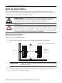
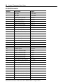
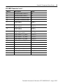
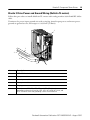
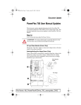
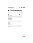
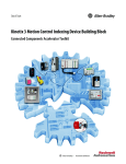
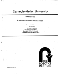
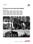
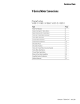
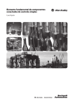
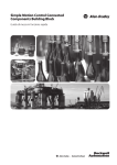
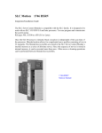
Installation Instructions
Kinetix 3 Component Servo Drives
Catalog Numbers 2071-AP0, 2071-AP1, 2071-AP2, 2071-AP4, 2071-AP8,
2071-A10, 2071-A15
Topic
Page
About the Kinetix 3 Drives
1
Important User Information
2
Catalog Number Explanation
3
Before You Begin
3
Connector Data
7
Power Wiring Requirements
12
Mating Connectors and Cables
13
Ground Your Kinetix 3 Drive to the Subpanel
14
Additional Resources
18
About the Kinetix 3 Drives
Kinetix 3 component servo drives provide simple solutions for applications with output power
requirements in the range of 1.30…12.37 A rms (50…1500 W).
Refer to the Kinetix 3 Component Drive User Manual, publication 2071-UM001, for detailed
information on wiring, applying power, troubleshooting, and integrating with MicroLogix
controller platforms.
For application-related information about Kinetix 3 drives, refer to the online help provided
with Ultraware software, version 1.79 or later, catalog number 2098-UWCPRG.
2
Kinetix 3 Component Servo Drives
Important User Information
Solid-state equipment has operational characteristics differing from those of electromechanical equipment.
Safety Guidelines for the Application, Installation and Maintenance of Solid State Controls (Publication
SGI-1.1 available from your local Rockwell Automation sales office or online at
http://www.rockwellautomation.com/literature/) describes some important differences between solid-state
equipment and hard-wired electromechanical devices. Because of this difference, and also because of the
wide variety of uses for solid-state equipment, all persons responsible for applying this equipment must
satisfy themselves that each intended application of this equipment is acceptable.
In no event will Rockwell Automation, Inc. be responsible or liable for indirect or consequential damages
resulting from the use or application of this equipment.
The examples and diagrams in this manual are included solely for illustrative purposes. Because of the many
variables and requirements associated with any particular installation, Rockwell Automation, Inc. cannot
assume responsibility or liability for actual use based on the examples and diagrams.
No patent liability is assumed by Rockwell Automation, Inc. with respect to use of information, circuits,
equipment, or software described in this manual.
Reproduction of the contents of this manual, in whole or in part, without written permission of Rockwell
Automation, Inc., is prohibited.
Throughout this manual, when necessary, we use notes to make you aware of safety considerations.
Identifies information about practices or circumstances that can cause an explosion in a
hazardous environment, which may lead to personal injury or death, property damage, or
economic loss.
Identifies information about practices or circumstances that can lead to personal injury or
death, property damage, or economic loss. Attentions help you identify a hazard, avoid a
hazard and recognize the consequences.
Labels may be on or inside the equipment, for example, drive or motor, to alert people that
dangerous voltage may be present.
Labels may be on or inside the equipment, for example, drive or motor, to alert people that
surfaces may reach dangerous temperatures.
IMPORTANT
Identifies information that is critical for successful application and understanding of
the product.
Rockwell Automation Publication 2071-IN001B-EN-P - August 2010
Kinetix 3 Component Servo Drives
3
Catalog Number Explanation
This publication applies to the following Kinetix 3 drives.
Cat. No.
Component Servo Drive (230V)
2071-AP0
Kinetix 3, 220V AC, 1 Ø, 0.6 A
2071-AP1
Kinetix 3, 220V AC, 1 Ø, 1.1 A
2071-AP2
Kinetix 3, 220V AC, 1 Ø, 1.7 A
2071-AP4
Kinetix 3, 220V AC, 1 Ø, 3.3 A
2071-AP8
Kinetix 3, 220V AC, 1 or 3 Ø, 5.0 A
2071-A10
Kinetix 3, 220V AC, 3 Ø, 7.0 A
2071-A15
Kinetix 3, 220V AC, 3 Ø, 9.9 A
Before You Begin
Remove all packing materials, wedges, and braces from within and around the components.
After unpacking, check the item nameplate catalog number against the purchase order.
Parts List
The Kinetix 3 drive ships with:
• a general purpose power input (IPD) header, shunt resistor (BC) header, and motor
power (MP) header.
• a connector tool for opening wire clamps on the power connector.
• a ground clamp and two #6-32 x 1 screws to provide ground and strain relief for the
motor power cable.
• these installation instructions, publication 2071-IN001.
Replacement connector sets (catalog number 2071-CONN1), are also available.
Refer to the Kinetix Motion Control Selection Guide, publication GMC-SG001, for more
information on replacement connector sets.
Rockwell Automation Publication 2071-IN001B-EN-P - August 2010
4
Kinetix 3 Component Servo Drives
Install the Kinetix 3 Drive
These procedures assume you have prepared your panel, and understand how to bond your
system. For installation instructions regarding equipment and accessories not included here, refer
to the instructions that came with those products.
SHOCK HAZARD: To avoid hazard of electrical shock, perform all mounting and
wiring of the Kinetix 3 drive prior to applying power. Once power is applied,
connector terminals may have voltage present even when not in use.
ATTENTION: Plan the installation of your system so that you can perform all
cutting, drilling, tapping, and welding with the system removed from the enclosure.
Because the system is of the open type construction, be careful to keep any metal
debris from falling into it. Metal debris or other foreign matter can become lodged
in the circuitry, which can result in damage to components.
Mount the Kinetix 3 Drive
Follow these steps to mount the drive.
1. Observe these clearance requirements when mounting the drive to the panel.
Dimensions are in millimeters (inches)
50.0 (1.97)
30.0 (1.18)
10.0 (0.39)
Minimum
Panel Depth
235 (9.25)
50.0 (1.97)
IMPORTANT
Mount the module in an upright position as shown. Do not mount the
module on its side.
2. Mount the Kinetix 3 drive to the cabinet subpanel with an M4 (#6-32) steel machine
screw torqued to 1.1 N•m (9.8 lb•in).
Rockwell Automation Publication 2071-IN001B-EN-P - August 2010
Kinetix 3 Component Servo Drives
5
Product Dimensions
Catalog Numbers 2071-AP0, 2071-AP1, and 2071-AP2
5.0
(0.2)
48.3
(1.9)
153.4
(6.04)
53.0
(2.09)
141.0
(5.55)
50.0
(1.97)
145.0
(5.71)
5.0
(0.20)
155.0
(6.11)
Mounting hole (top) and slot
(bottom) require M4 x 10 bolts.
Chassis Ground
Terminal (1)
Dimensions are in millimeters (inches). Drives are designed to metric dimensions; inches are a mathematical conversion.
Catalog Number 2071-AP4
58.0
(2.29)
153.4
(6.04)
5.0
(0.20)
48.3
(1.9)
50.0
(1.97)
141.0
(5.55)
155.0
(6.11)
145
(5.71)
5.0
(0.20)
Mounting hole (top) and slot
(bottom) require M4 x 10 bolts.
Chassis Ground Terminals (2)
Dimensions are in millimeters (inches). Drives are designed to metric dimensions; inches are a mathematical conversion.
Rockwell Automation Publication 2071-IN001B-EN-P - August 2010
6
Kinetix 3 Component Servo Drives
Catalog Numbers 2071-AP8, 2071-A10, and 2071-A15
5.0
(0.2)
81.0
(3.19)
50.0
(1.97)
198.6
(7.82)
59.0
(2.32)
186.2
(7.34)
145.0
(5.71)
Mounting hole (top) and slot (bottom)
require M5 x 10 bolts.
155.0
(6.11)
Chassis Ground
Terminals (2)
Dimensions are in millimeters (inches). Drives are designed to metric dimensions; inches are a mathematical conversion.
Rockwell Automation Publication 2071-IN001B-EN-P - August 2010
Kinetix 3 Component Servo Drives
7
Connector Data
Use this illustration to identify the Kinetix 3 drive features and indicators.
Kinetix 3 Drive Features and Indicators
Item
Description
15
1
Left/right and up/down keys
14
2
Analog output (A.out)
1
13
3
RS-485 communication termination
switch
2
12
4
Input power (IPD)
5
Main power indicator
6
Shunt power (BC)
7
Motor power (MP)
8
Ground lug
9
Motor feedback (MF)
10
Input/output (I/O)
11
Serial interface (Comm0B) (down)
3
11
4
I/O
10
DC -
12
Serial interface (Comm0A) (up)
6
13
Enter key
14
Mode/set key
15
7-segment status indicator
Motor Feedback
5
7
9
8
Kinetix 3 Drive Connectors
Designator
Description
Connector
A.out
Analog output
4-pin connector header
IPD
AC and control power input
6-pin quick-connect terminal block
BC
Shunt power
2-pin quick-connect terminal block
MP
Motor power
3-pin quick-connect terminal block
CommOA
Serial interface up
6-pin IEEE 1394 connector
CommOB
Serial interface down
6-pin IEEE 1394 connector
IOD
I/O
50-pin mini-D connector
MF
Motor feedback
20-pin mini-D connector
Rockwell Automation Publication 2071-IN001B-EN-P - August 2010
8
Kinetix 3 Component Servo Drives
Analog Output (A.out) Connector
A.out Pin
Description
Signal
1
Analog output #1
AOUT1
2
Analog output #1 ground
ACOM
3
Analog output #2
AOUT2
4
Analog output #2 ground
ACOM
Input Power (IPD) Connector
IPD Pin
Description
Signal
L1
Main AC power
L1
L2
Main AC power
L2
(1)
L3
Main AC power
L3
L1C
L1C - Control power
L1C
L2C
L2C - Control power
L2C
DC
DC bus negative
DC- (not supported)
(1)
L3 is not used for single phase drives.
Shunt Power (BC) Connector
BC Pin
Description
Signal
B1
Shunt resistor +
DC bus positive
B1
(not supported)
B2
Shunt resistor -
B2
Motor Power (MP) Connector
MP Pin
Description
Signal
U
Motor power U
U
V
Motor power V
V
W
Motor power W
W
Rockwell Automation Publication 2071-IN001B-EN-P - August 2010
Kinetix 3 Component Servo Drives
9
Motor Feedback (MF) Connector
MF Pin
Description
Signal
1
Encoder power ground
ECOM
2
Thermal sensor input
TS
3
A positive differential input
A+
4
A negative differential input
A-
5
B positive differential input
B+
6
B negative differential input
B-
7
Index positive differential input
I+
8
Index negative differential input
I-
9
Negative limit sensor input
LMT-
10
Serial positive
Hall feedback S1
SD+
S1
11
Shield drain
GND
12
Reserved
—
13
Serial negative
SD-
14
Hall feedback S2
S2
15
Reserved
—
16
Hall feedback S3
S3
17
Positive limit sensor input
LMT+
18
BAT+ for motor side
BAT+
19
BAT- for motor side
BAT-
20
Encoder +5 input power
EPWR
Serial Interface (Comm0A, up) and (Comm0B, down) Connector
CommOA and
CommOB Pin
Description
1
RS-232 transmit
XMT
2
RS-232 receive
RCV
3
Reserved
—
4
+5V power ground
GND
5
RS-485 +
DX+
6
RS-485 -
DX-
Signal
Rockwell Automation Publication 2071-IN001B-EN-P - August 2010
10
Kinetix 3 Component Servo Drives
I/O (IOD) Connector
IOD Pin
Description
Signal
1
24V Input
+24V PWR
2
24V Input
+24V PWR
3
Digital input 1 (/SV-ON)
INPUT1
4
Digital input 2 (P-OT)
INPUT2
5
Digital input 3 (N-OT)
INPUT3
6
Digital input 4 (/P-CON)
INPUT4
7
Digital input 5(/A-RST))
INPUT5
8
Digital input 6 (/N-TL)
INPUT6
9
Digital input 7 (/P-TL)
INPUT7
10
ESTOP (default: disable)
ESTOP
11
Follower input A+
PLUS +
12
Follower input A-
PLUS -
13
Follower input B+
SIGN +
14
Follower input B-
SIGN -
15
High frequency pulse input A+
HF_PULS +
16
High frequency pulse input A-
HF_PULS -
17
Encoder z-pulse
Z-PULSE+
18
Encoder z-pulse
Z-PULSE-
19
Velocity command input+
VCMD+
20
Velocity command input-
VCMD-
21
Current command input+
ICMD+
22
Current command input-
ICMD-
23
High frequency pulse input B+
HF_SIGN +
24
High frequency pulse input B-
HF_SIGN -
25
O/C for sign of 24V level
24V_SIGN +
26
Digital input 8
INPUT8
27
Digital input 9
INPUT9
28
Digital input 10
INPUT10
29
Buffered encoder channel A+
AM+
30
Buffered encoder channel A-
AM-
31
Buffered encoder channel B+
BM+
32
Buffered encoder channel B-
BM-
Rockwell Automation Publication 2071-IN001B-EN-P - August 2010
Kinetix 3 Component Servo Drives
11
I/O (IOD) Connector (cont.)
IOD Pin
Description
Signal
33
Buffered encoder channel Z+
IM+
34
Buffered encoder channel Z-
IM-
35
Serial data of absolute encoder
PS+
36
Serial data of absolute encoder
PS-
37
Alarm output 1
Digital output4
FAULT1
OUTPUT4
38
Alarm output 2
Digital output5
FAULT2
OUTPUT5
39
Alarm output 3
Digital output6
FAULT3
OUTPUT6
40
Alarm output
Digital outputs ground
FCOM
OUT COM
41
Digital output 1 + (P_COM+)
OUTPUT1+
42
Digital output 1 – (P_COM-)
OUTPUT1-
43
Digital output 2 + (TG_ON+)
OUTPUT2+
44
Digital output 2 – (TG_ON-)
OUTPUT2-
45
Servo alarm +
FAULT+
46
Servo alarm -
FAULT-
47
Digital output 3 + (BK+)
OUTPUT3+
48
Digital output 3 – (BK-)
OUTPUT3-
49
O/C for pulse of 24V level
24V_PULS +
50
Reserved
—
Rockwell Automation Publication 2071-IN001B-EN-P - August 2010
12
Kinetix 3 Component Servo Drives
Power Wiring Requirements
Wire should be copper with 75 °C (167 °F) minimum rating. Phasing of main AC power is
arbitrary and earth ground connection is required for safe and proper operation.
Terminals
Cat. No.
Description
Pin
2071-AP0
2071-AP1
2071-AP2
2071-AP4
2071-AP8
Input and control
power
2071-A10
2071-A15
2071-xxx
2071-xxx
(1)
Motor power
Shunt resistor (1)
Signal
Recommended
Wire Size
mm2 (AWG)
Strip
Length
mm (in.)
Torque Value
N•m (lb•in)
IPD-L1
IPD-L2
IPD-L1C
IPD-L2C
L1
L2
L1C
L2C
N/A
Ground screw
Ground
1.25 (11)
IPD-L1
IPD-L2
(IPD-L3)
IPD-L1C
IPD-L2C
L1
L2
(L3)
L1C
L2C
N/A
Ground screw
Ground
1.25 (11)
2.5 (14)
8 (0.3)
IPD-L1
IPD-L2
IPD-L3
IPD-L1C
IPD-L2C
L1
L2
L3
L1C
L2C
Ground screw
Ground
1.25 (11)
MP-U
MP-V
MP-W
U
V
W
N/A
Ground screw
GND
1.25 (11)
BC-B1
BC-B2
B1
B2
N/A
N/A
Use for shunt resistor connection only.
ATTENTION: To avoid personal injury and/or equipment damage, make sure
installation complies with specifications regarding wire types, conductor sizes,
branch circuit protection, and disconnect devices. The National Electrical Code
(NEC) and local codes outline provisions for safely installing electrical equipment.
To avoid personal injury and/or equipment damage, make sure motor power
connectors are used for connection purposes only. Do not use them to turn the unit
on and off.
To avoid personal injury and/or equipment damage, make sure shielded power
cables are grounded to prevent potentially high voltages on the shield.
Rockwell Automation Publication 2071-IN001B-EN-P - August 2010
Kinetix 3 Component Servo Drives
13
Mating Connectors and Cables
Connector
Type of Connector
Wire Size
Cat. No.
2
Output (Motor) Power
Single-row, spring clamp
connectors with 7.5 mm
(0.30 in.) spacing
2.5…0.08 mm
(12…28 AWG)
8 mm (0.31 in.) of
wire exposed
Input/Output
50-pin mini-D
Motor Feedback
20-pin mini-D
0.25…0.05 mm2
(24…30 AWG)
Input Power
(1)
2071-CONN1 (1)
2071-TBIO
2071-TBMF
The tool (Wago 231-131) for opening individual cage-clamp power connectors is supplied with the drive. You can purchase
the replacement tool separately.
Connector
Type of Mating Cable
Cable
2090-CCMPCDS-23AA01
Configuration
2090-CCMPCDS-23AA03
Serial Interface
Comm0A, Comm0B
2090-CCMCRDS-48AA01
Control
2090-CCMCRDS-48AA03
2090-CCMDSDS-48AA01
Drive to drive control
2090-CCMDSDS-48AAP3
Rockwell Automation Publication 2071-IN001B-EN-P - August 2010
14
Kinetix 3 Component Servo Drives
Ground Your Kinetix 3 Drive to the Subpanel
If the Kinetix 3 drive is mounted on a painted subpanel, bond it to the cabinet ground bus. To do
this, attach a braided ground strap or 0.4 mm2 (12 AWG) solid copper wire that is 100 mm
(3.9 in.) long between the top mounting screw and the bonded cabinet ground.
Connecting the Braided Ground Strap Example
2
1
3
4
5
Item
Description
1
Mounting screw
2
Braided ground strap
3
Bonded cabinet ground bus
4
Ground grid or power distribution ground
5
2071-AP4 Kinetix 3 drive shown
Rockwell Automation Publication 2071-IN001B-EN-P - August 2010
Kinetix 3 Component Servo Drives
15
Kinetix 3 Drive Power and Ground Wiring (Bulletin TL motors)
Follow this procedure to install a Bulletin TL motor with catalog number 2090-DANPT-16Sxx
cable.
Terminate the power-input ground wire with a ring lug. Attach input-power and motor-power
grounds to ground screws, and torque to 1.25 N•m (11 lb•in).
1
2
3
4
5
6
Item
Description
1
2071-AP4 Kinetix 3 drive shown.
2
Input power cable.
3
Control power cable.
4
Motor power cable.
5
Ring lug.
6
Ground screw, 2071-AP0, 2071-AP1, and 2071-AP2 drives have one
grounding screw on the heatsink. 2071-AP4, 2071-AP8, 2071-A10, and
2071-A15 drives have two grounding screws on the heatsink.
Rockwell Automation Publication 2071-IN001B-EN-P - August 2010
16
Kinetix 3 Component Servo Drives
Kinetix 3 Drive Power and Ground Wiring (Bulletin TLY, LDC-Series, and
LDL-Series motors and MPAS and TLAR actuators)
Follow this procedure to install Bulletin TLY, LDC-Series, and LDL-Series motors and MPAS
and TLAR actuators with catalog number 2090-CPWM4DF-xxAFxx or
2090-CPWM6DF-16AAxx.
1. Terminate the power-input ground wire with a ring lug as shown in Kinetix 3 Drive
Power and Ground Wiring (Bulletin TL motors) on page 15.
1
2
25
(1.0)
12.7
(0.50)
34.0
(1.34)
50…75
(2…3)
8
7
3
4
50…75
(2…3)
5
Dimensions are in millimeters (inches)
6
Item
Description
1
2071-AP4 Kinetix 3 drive shown.
2
Motor-power ground clamp.
3
Motor power cable.
4
Expose 25 mm (1 in.) of cable shield.
5
If panel is painted, remove paint to provide metal-to-metal contact.
6
Sub panel.
7
Ring lug.
8
Ground screw. 2071-AP0, 2071-AP1, and 2071-AP2 drives have one
grounding screw on the heatsink. 2071-AP4, 2071-AP8, 2071-A10,
and 2071-A15 drives have two grounding screws on the heatsink.
2. Terminate motor-power ground wire with a ring lug.
Rockwell Automation Publication 2071-IN001B-EN-P - August 2010
Kinetix 3 Component Servo Drives
17
3. Attach power-input ground wire and motor-power ground wire to ground screws.
4. Torque the ground screw to 1.25 N•m (11 lb•in).
5. Locate a suitable position for installing the cable shield clamp within 50…75 mm
(2…3 in.) of the drive.
6. Lay out and drill holes for the cable clamp.
ATTENTION: Plan the installation of your system so that you can perform all
cutting, drilling, tapping, and welding with the system removed from the enclosure.
Because the system is of the open type construction, be careful to keep any metal
debris from falling into it. Metal debris or other foreign matter can become lodged
in the circuitry, which can result in damage to components.
7. Locate the position on the motor power cable that comes under the clamp and remove
about an 25.4 mm (1 in.) of the cable jacket to expose the shield braid.
8. Position the exposed portion of the cable braid directly in line with the clamp.
9. Clamp the exposed shield to the panel with the clamp and two #6-32 x 1 screws
provided.
10. Repeat steps 1…9 for each Kinetix 3 drive you are installing.
.
Rockwell Automation Publication 2071-IN001B-EN-P - August 2010
18
Kinetix 3 Component Servo Drives
Additional Resources
These documents contain additional information concerning related Rockwell Automation
products.
Resource
Description
Kinetix 3 Component Servo Drive User Manual,
publication 2071-UM001
Information on installing, configuring, starting up,
troubleshooting, and specifications for your Kinetix 3 servo
drive system.
Motor Feedback Breakout Board Installation
Instructions, publication 2071-IN003
Information on installing and wiring a Kinetix 3 motor
feedback breakout board.
I/O Breakout Board Installation Instructions,
publication 2071-IN002
Information on installing and wiring a Kinetix 3 motor I/O
breakout board.
Serial Communication Cables Installation
Instructions, publication 2090-IN019
Information on installing and schematics for the serial
communication cables used with a Kinetix 3 drive.
MicroLogix 1100 Programmable Controllers
Installation Instructions, publication 1763-IN001
Information on how to assemble and mount the controller,
how to upgrade firmware, and controller technical
specifications.
Information on how to assemble and mount the controller,
MicroLogix 1400 Programmable Controllers
Installation Instructions, publication 1766-IN001 how to upgrade firmware, and controller technical
specifications.
Kinetix 3 Component Servo Drive Serial Host
Command Reference Manual, publication
2071-RM001
Information on the serial communication commands, both
ASCII and ModBus, for interfacing a motion controller
with the Kinetix 3 drive.
Industrial Automation Wiring and Grounding
Guidelines, publication 1770-4.1
Provides general guidelines for installing a Rockwell
Automation industrial system.
Product Certifications website,
http://www.ab.com
Provides declarations of conformity, certificates, and other
certification details.
You can view or download publications at http://www.rockwellautomation.com/literature/. To
order paper copies of technical documentation, contact your local Rockwell Automation
distributor or sales representative.
Rockwell Automation Publication 2071-IN001B-EN-P - August 2010
Kinetix 3 Component Servo Drives
19
Notes:
Rockwell Automation Publication 2071-IN001B-EN-P - August 2010
Rockwell Automation Support
Rockwell Automation provides technical information on the Web to assist you in using its products. At
http://www.rockwellautomation.com/support/, you can find technical manuals, a knowledge base of FAQs,
technical and application notes, sample code and links to software service packs, and a MySupport feature that
you can customize to make the best use of these tools.
For an additional level of technical phone support for installation, configuration and troubleshooting, we offer
TechConnect support programs. For more information, contact your local distributor or Rockwell Automation
representative, or visit http://www.rockwellautomation.com/support/.
Installation Assistance
If you experience a problem within the first 24 hours of installation, please review the information that's
contained in this manual. You can also contact a special Customer Support number for initial help in getting your
product up and running.
United States or Canada 1.440.646.3434
Outside United States
or Canada
Use the Worldwide Locator at
http://www.rockwellautomation.com/support/americas/phone_en.html, or contact
your local Rockwell Automation representative.
New Product Satisfaction Return
Rockwell Automation tests all of its products to ensure that they are fully operational when shipped from the
manufacturing facility. However, if your product is not functioning and needs to be returned, follow these
procedures.
United States
Contact your distributor. You must provide a Customer Support case number (call the
phone number above to obtain one) to your distributor to complete the return process.
Outside United States
Please contact your local Rockwell Automation representative for the return
procedure.
Documentation Feedback
Your comments will help us serve your documentation needs better. If you have any suggestions on how to
improve this document, complete this form, publication RA-DU002, available at
http://www.rockwellautomation.com/literature/.
Allen-Bradley, Kinetix, LDC-Series, LDL-Series, MicroLogix, Rockwell Software, Rockwell Automation, TechConnect, and Ultraware are
trademarks of Rockwell Automation, Inc.
Trademarks not belonging to Rockwell Automation are property of their respective companies.
Rockwell Otomasyon Ticaret A.Ş., Kar Plaza İş Merkezi E Blok Kat:6 34752 İçerenköy, İstanbul, Tel: +90 (216) 5698400
Rockwell Automation Publication 2071-IN001B-EN-P - August 2010
PN-85627
Supersedes Publication 2071-IN001A-EN-P - April 2010 and 2071-DU001A-EN-P - August 2010 Copyright © 2010 Rockwell Automation, Inc. All rights reserved. Printed in the U.S.A.