1
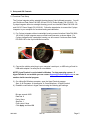
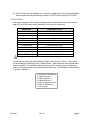
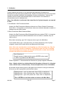
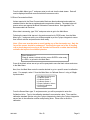
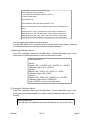
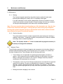
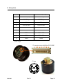
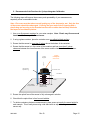
Cyclops Integrator User’s Manual August 7, 2015 P/N 998-2602 Revision B TURNER DESIGNS 845 W. Maude Avenue Sunnyvale, CA 94085 Phone: (408) 749-0994 FAX: (408) 749-0998 Table of Contents 1. Introduction 1.1 Description 1.2 Sensors 1.3 Accessories 1.4 Engineering Units 1.5 Data Stream 4 4 4 4 4 Setup and GUI Controls 2.1 Functional Test Setup 2.2 GUI Controls 5 6 Calibration 3.1 Raw Fluorescence Mode 3.2 Raw Fluorescence Blank Subtracted Mode 3.3 Direct Concentration Mode 3.4 Reporting Calibration Values 3.5 Clearing All Calibrations 7 7 8 8 8 4. Integration 10 5. Maintenance and Warranty 5.1 Maintenance 5.1.1 Rinsing 5.1.2 Optics 5.2 Warranty Terms 5.3 Warranty Service 5.4 Out of Warranty Service 11 11 11 11 12 12 2. 3. Appendix A. B. C. D. Specifications Wiring Guide Recommended Lab Practices for Cyclops Integrator Calibration Temperature Compensation, Linear Range and Quenching 13 14 15 16 WASTE ELECTRICAL AND ELECTRONIC EQUIPMENT (WEEE) DIRECTIVE Turner Designs is in the business of designing and selling products that benefit the well-being of our environment. Accordingly, we are concerned with preserving the surroundings wherever our instruments are used and happy to work with customers by complying with the WEEE Directive to reduce the environmental impact resulting from the use of our products. WEEE Return Process: To arrange the return of an end-of-life product, proceed as follows: If you purchased your instrument through a Turner Designs Distributor please contact your local representative. They will instruct you where to return the end-of-life product. If you purchased your instrument directly from Turner Designs please contact Turner Designs Customer Service By Phone: 1-408-212-4041 or Toll Free: (877) 316.8049 By Email: Customer Service at [email protected] Turner Designs will provide a WEEE RMA Number, a Shipping Account Number, and a Ship to Address. Package and ship the product back to Turner Designs. The product will be dealt with per Turner Designs’ end-of-life recycling program in an environmentally friendly way. 998-2602 Rev. B Page 3 1. Introduction 1.1 Description The Cyclops Integrator provides a package optimized for integrating Cyclops sensors into vehicles. One, two, or three optical sensors ranging from deep ultraviolet to infrared can be mounted with the Cyclops Integrator electronics in a very compact footprint. Submersible to 1000m, the Cyclops Integrator is available with or without a watertight housing. 1.2 Sensors The sensor(s) configured with the Cyclops Integrator are in situ sensors that detect relative fluorescence of specific fluorophores in water. They use solid state optoelectronics, an LED-based light source, a photodiode for detection of fluorescence, and interference filters for maximizing or selecting fluorophores of interest. The sensors have low power consumption and superior signal stability. Sensors are factory-installed in the Cyclops Integrator package and cannot be changed or reconfigured for different applications once the package is assembled and received by the customer. 1.3 Accessories Anti-fouling Copper Tape (5 sets) P/N 2600-506 Solid Secondary Standard Cap P/N 2600-900 Solid Secondary Standard (SSS) for in vivo Chlorophyll, Phycocyanin, Phycoerythrin, Rhodamine, and Fluorescein P/N: 2600-901. See Accessory Instructions on the USB Flash Drive for more information. Solid Secondary Standard (SSS) for UV Sensors - CDOM/FDOM, Optical Brighteners, Tryptophan, Refined Fuels and Crude Oil P/N: 2600-902. See Accessory Instructions on the USB Flash Drive for more information. Note: Solid Secondary Standard not available for turbidity. 1.4 Engineering Units The engineering units reported by the installed sensors are Relative Fluorescence Units (RFU). The RFU signal is proportional to the amount of fluorescence detected by the sensor. In other words, high RFU values represent a high amount of fluorescence detected and low RFU values mean there is a low amount of fluorescence detected. Customers have the option of calibrating their sensors using known standards for the purpose of converting RFU to actual concentration estimates. 1.5 Data Stream A few seconds after power is supplied to the Cyclops Integrator, data will stream at a rate of once per second. The data stream can be captured by any data logger capable of capturing ASCII data. The Cyclops Integrator is not capable of storing data in memory; it is only capable of streaming data out to a third-party data logger. Note: Any data that are not captured by third-party data loggers cannot be retrieved. 998-2602 Rev. B Page 4 2. Setup and GUI Controls 2.1 Functional Test Setup The Cyclops Integrator with a watertight housing has an 8-pin bulkhead connector. You will use Continuous Data Cable P/N 2200-160 and 12V DC Power Supply P/N 159-0191. For Cyclops Integrator without a watertight housing you will use Interface Cable P/N 2600-160 and 12V DC Power Supply P/N 159-0191. Follow the steps below to connect the Cyclops Integrator to your computer for functional testing and calibration. 1) For Cyclops Integrator without a watertight housing connect Interface Cable P/N 2600160 to the Cyclops Integrator sensor control board connector as shown below. For Cyclops Integrator with a watertight housing you will connect Continuous Data Cable P/N 2200-160 to the 8-pin bulkhead connector. 2) Connect the cable’s serial plug to your computer’s serial port, or USB using a Serial to USB cable adaptor if a serial port is not available. NOTE: HyperTerminal is not included in Windows 7 or later operating system. If HyperTerminal is not available you can contact [email protected], or use another similar terminal program. 3) On a MicroSoft Windows computer, open the HyperTerminal program. Start All Programs Accessories Communications HyperTerminal 4) Establish a connection in HyperTerminal using the following port settings: Bits per second: 9600 Data bits: 8 Parity: None Stop bits: 1 Flow control: None Click Apply and then OK 998-2602 Rev. B Page 5 5) Once the HyperTerminal displays it is connected, supply power to the Cyclops Integrator sensor control board by connecting the cable to 12V DC Power Supply P/N 159-0191. 2.2 GUI Controls After supplying power to the Cyclops Integrator sensor control board, hold a white sheet of paper in front of the sensor face to determine if the sensor is functioning. Application Light Source Color Blue Infra Red (No Color) Yellow-Orange Green Blue Green Ultra Violet (No Color)* Deep Ultra Violet (No Color)* Ultra Violet (No Color)* Ultra Violet (No Color)* Ultra Violet (No Color)* In Vivo Chlorophyll Turbidity Phycocyanin Phycoerythrin Fluorescein Rhodamine CDOM/FDOM Refined Oils and Fuels Crude Oil Optical Brighteners PTSA *Do not look directly at the optics. Ultraviolet light can be damaging to the eyes. You should see a blue light emitted from the paper if checking a UV sensor. There will be no observable light emitting from the Turbidity sensor. Data will stream a few seconds after power is supplied. To stop data streaming and access GUI controls, type ‘cal’ and press enter on the Hyperterminal screen while data are streaming. The Main Menu should display 7 options, numbered 1-7. 1. Set Blank for All Sensors 2. Calibrate Sensor 1 3. Calibrate Sensor 2 4. Calibrate Sensor 3 5. Report Calibration Values 6. Clear All Calibrations 7. Exit Program 998-2602 Rev. B Page 6 3. Calibration Cyclops Integrator sensors are in situ instruments that read relative fluorescence of fluorophores in water and report qualitative data. Relative Fluorescence Units can be converted to actual concentration estimates using standards of known concentrations. However, the qualitative nature of these measurements allows for inaccuracies in the estimation of concentrations even for calibrated units. Note: If no calibration is performed, data output from the Cyclops Integrator are reported as RFU. 3.1 Uncalibrated - Raw Fluorescence Mode Values in the Raw Fluorescence Mode are referred to as “Raw or Relative Fluorescence Units” (RFU). It is important to note that these values are not blank subtracted or scaled to a standard; they are relative values. 3.2 Raw Fluorescence Blank Subtracted Mode Values in the Raw Fluorescence Blank Subtracted Mode are noted as RFUB. It is important to note that these values are blank subtracted but are not scaled to a standard; they are relative values. When data is streaming, type “CAL” and press enter to get to the Main Menu. From the Main Menu type ‘1’ and press enter; you will be prompted to put the Cyclops Integrator’s sensor face in blank solution and press enter when ready. Note: Extra care must be taken to avoid getting any of the electronics wet. Only the face of the sensor should be submerged. Covering the open end of the CI housing with a plastic bag and securing to the threaded section with a rubber band will help minimize the impact of accidental splashes. Enter Selection>>1 Place all sensors in blank solution, press <ENTER> when ready or <ESC> to go back to the Main Menu Refer to Appendix C - Recommended Lab Practices for Cyclops Integrator Calibration. Note: A blank solution is a solution without the fluorophore of interest (i.e. deionized water, artificial water, or filtered water). Ensure the optical face is free of air bubbles. As the blank values are being set they will appear on the screen for each gain and sensor. At the end you will be prompted to save the blank values. Reading sensor 1, gain 1X, please wait...Press <ESC> to stop/cancel Reading sensor 1, gain 10X, please wait...Press <ESC> to stop/cancel Reading sensor 1, gain 100X, please wait...Press <ESC> to stop/cancel… … Press <ENTER> to save blank values and return to the Main Menu 998-2602 Rev. B Page 7 From the Main Menu type ‘7’ and press enter to exit and view the data stream. Data will now be displayed as blank corrected relative fluorescence units. 3.3 Direct Concentration Mode Values reported in the Direct Concentration Mode are blank subtracted and scaled to a standard solution that has a predetermined concentration estimate. The steps below will ensure values are reported as Blank Subtracted Concentrations. See Appendix C for Recommended Lab Practices. When data is streaming, type “CAL” and press enter to get to the Main Menu. Following the same initial step as in the previous section for RFUB mode, from the Main Menu type ‘1’ and press enter; you will be prompted to put the Cyclops Integrator’s sensor face in blank solution and press enter when ready. Note: Extra care must be taken to avoid getting any of the electronics wet. Only the face of the sensor should be submerged. Covering the open end of the CI housing with a plastic bag and securing to the threaded section with a rubber band will help minimize the impact of accidental splashes. Enter Selection>>1 Place all sensors in blank solution, press <ENTER> when ready or <ESC> to go back to the Main Menu Once all the blank values are set you will be prompted to save the blank values and return to the Main Menu. Next, from the Main Menu enter the number desired to go to a specific sensor’s calibration menu. For example, select ‘2’ from the Main Menu to Calibrate Sensor 1 using a 100ppb liquid standard. 1. Set Blank for All Sensors 2. Calibrate Sensor 1 3. Calibrate Sensor 2 4. Calibrate Sensor 3 5. Report Calibration Values 6. Clear All Calibrations 7. Exit Program From the Sensor Menu type ‘2’ and press enter; you will be prompted to enter the Calibration Value. Type in the calibration standard’s concentration value. Then read the calibration standard solution using the Cyclops Integrator by placing the Cyclops Integrator’s sensor face in the calibration solution and pressing enter. Press enter to save the calibration. 998-2602 Rev. B Page 8 1. Set Blank for Sensor 1 (if not already set) 2. Set Calibration Value for Sensor 1 3. Clear Blank and Calibration Values for Sensor 1 4. Return to Main Menu Enter Selection>>2 Enter Calibration Value then press <ENTER>: 100 Place the CI sensor face in the calibration solution, press <ENTER> when ready Reading sensor 1, gain 1X, please wait...Press <ESC> to stop/cancel Reading sensor 1, gain 10X, please wait...Press <ESC> to stop/cancel Reading sensor 1, gain 100X, please wait...Press <ESC> to stop/cancel Press <ENTER> to save calibration values and return to the Main Menu You can repeat these steps for the other sensors. From the Main Menu type ‘7’ and press enter to exit and view the data stream. Data from the calibrated sensors are now reported as concentration estimates. 3.4 Reporting Calibration Values. Type “CAL” and press enter to get to the Main Menu. From the Main Menu type ‘5’ and press enter; the Calibration Values for all the sensors will be shown. Enter Selection>>5 Sensor 1 Blanks: x100 = 1163 RFU, x10 = 133 RFU, x1 = 169 RFU Calibration Value 0.00 = 1167 RFU Sensor 2 Blanks: x100 = 0 RFU, x10 = 0 RFU, x1 = 0 RFU Calibration Value 0.00 = 0 RFU Sensor 3 Blanks: x100 = 0 RFU, x10 = 444 RFU, x1 = 451 RFU Calibration Value 100.00 = 35892 RFU Press <ENTER> to return to the Main Menu 3.5 Clearing all Calibration Values. Type “CAL” and press enter to get to the Main Menu. From the Main Menu type ‘6’ and press enter; you will be prompted if you want to clear the calibration values for all the sensors. Enter Selection>>6 This will clear the calibration values for all Sensors, are you sure? (Y/N): y 998-2602 Rev. B Page 9 4. Integration Once the Cyclops Integrator sensors have been tested and/or calibrated you can proceed with integration into your third party platform. Refer to the power requirements in Attachment A to make sure that your system is set up correctly. Refer to the Wiring Guide in Attachment B for the correct wiring configuration. Three seconds after power is supplied to the instrument, data will stream at once per second. The Cyclops Integrator is available in configurations with and without a watertight housing. Bevels are provided on the face of the instrument to match the exterior contours of a cylindrical vessel. If no watertight housing is supplied, the customer is responsible for supplying a housing that is watertight and for using the Cyclops sensors at a depth and pressure that is rated appropriately for the sensors installed no more than 1000 meters. 998-2602 Rev. B Page 10 5. Maintenance and Warranty 5.1 Maintenance 5.1.1 Rinsing The Cyclops Integrator optical face should be rinsed or soaked in fresh water following each deployment, ideally until it is completely clean again. If an open instrument is to be stored, please keep in a warm, dry location to avoid moisture accumulation around the optics. Excess moisture in the air may condense on the optics when deployed in cool water, which could affect the data. Note: Extra care must be taken to avoid getting any of the electronics wet. Only the face of the sensor should be submerged. Covering the open end of the Cyclops Integrator housing with a plastic bag and securing to the threaded section with a rubber band will help minimize the impact of accidental splashes. 5.1.2 Care for the optics The optical window should be visually inspected after each deployment following a soaking in fresh water. If cleaning is needed, use optical tissue to clean the window with soapy water or ethanol/isopropanol Note: The Cyclops should NOT come in contact with any organic solvents (i.e. acetone) or strong acids and bases. 5.2 Warranty Terms Turner Designs warrants the Cyclops Integrator and accessories to be free from defects in materials and workmanship under normal use and service for a period of 12 months from the date of shipment from Turner Designs with the following restrictions: Turner Designs is not responsible for replacing parts damaged by accident or neglect. Your instrument must be installed according to instructions in the User’s Manual. Damage from corrosion is not covered. Damage caused by customer modification of the instrument is not covered. This warranty covers only Turner Designs products and is not extended to equipment used with our products. We are not responsible for incidental or consequential damages, except in those states where this limitation is not allowed. This warranty gives you specific legal rights and you may have other rights which vary from state to state. Damage incurred in shipping is not covered. 998-2602 Rev. B Page 11 5.3 Warranty Service To obtain service during the warranty period, the owner shall take the following steps: 1. Write, email or call Turner Designs Technical Support and describe as precisely as possible the nature of the problem. Phone: 1 (877) 316-8049 Email: [email protected] 2. Carry out any adjustments or tests as suggested by Technical Support. 3. If proper performance is not obtained you will be issued a Return Materials Authorization number (RMA) to reference. Package the unit, write the RMA number on the outside of the shipping carton, and ship the instrument, prepaid, to Turner Designs. If the failure is covered under the warranty terms the instrument will be repaired and returned free of charge, for all customers in the contiguous continental United States. For customers outside of the contiguous continental United States who purchased equipment from one of our authorized distributors, contact the distributor. If you purchased directly, contact us. We will repair the instrument at no charge. Customer pays for shipping, duties, and documentation to Turner Designs. Turner Designs pays for return shipment (custom duties, taxes and fees are the responsibility of the customer). 5.4 Out-of-Warranty Service Follow steps for Warranty Service as listed above. If Technical Support can assist you by phone or correspondence, we will be glad to, at no charge. Repair service will be billed on a fixed price basis, plus any applicable duties and/or taxes. Shipment to Turner Designs should be prepaid. Your bill will include return shipment freight charges. Address for Shipment: Turner Designs, Inc. 845 W. Maude Ave. Sunnyvale, CA 94085 998-2602 Rev. B Page 12 A. Specifications Cyclops Integrator Sensor Control Board Minimum Power Supply 12-30V; 3W Maximum Current Draw with 3 sensors - Operational ~80mA Data Output RS232 (ASCII) Sample Interval 1 second Baud Rate 9600 Diameter <3 inches (7.7 cm) Height without sealed housing 1.625 inches (4.1 cm) Height with sealed housing 3.15 inches (8 cm) Sensors Operational Temperature -2 to 50 C Depth Options 0 to1000 meters 998-2602 Rev. B Page 13 B. Wiring Guide Pin Out Interface Firmware Updating 1 POWER (+) POWER (+) 2 POWER (-) POWER (-) 3 RX RX 4 DIGITAL GND DIGITAL GND 5 TX TX 6 OPEN OPEN 7 OPEN DTR & DSR 8 OPEN RTS & CTS 9 OPEN OPEN ASCII output CI connector mates with Molex 51021-0900 1 2 3 4 5 6 7 8 9 CI pins 8 2 1 7 3 4 6 5 998-2602 Rev. B Page 14 C. Recommended Lab Practices for Cyclops Integrator Calibration The following steps will improve the accuracy and repeatability of your measurements, especially at low concentration levels: Note: Extra care must be taken to avoid getting any of the electronics wet. Only the face of the sensor should be submerged. Covering the open end of the CI housing with a plastic bag and securing to the threaded section with a rubber band will help minimize the impact of accidental splashes. 1. Use a non-fluorescent container for your water samples. Note: Plastic may fluoresce and interfere with the sample’s fluorescence. 2. If using a glass container, place the container on a non-reflective black surface. 3. Ensure that the sensor is more than 3 inches above the bottom of the container. 4. Ensure that the sensor is in the center of the container and has more than 2 inches clearance between the circumference of the sensor and the inside surface of the beaker. Cyclops Integrator Lab stand with adjustable ring CAUTION Do NOT get the electronics wet. >2 inches all round Glass Beaker >3 inches No Air Bubbles On Optical Surface Dark/Black NonReflective Surface 5. Ensure the optical face of the sensor is fully submerged in solution. 6. Check that the optical face is free from air bubbles.. 7. To obtain consistency between measurements, place sensor at exactly the same height for each sample. This is easily done using a lab stand with an adjustable ring secured to the sensor cap. 998-2602 Rev. B Page 15 D. Temperature Compensation, Linear Range and Quenching Temperature Compensation Fluorescence is temperature sensitive. As the temperature of the sample increases, the fluorescence decreases. For greatest accuracy, record the sample temperature and correct the sensor output for changes in temperature. The following are Temperature Coefficients for common fluorescent applications: Application Temperature Coefficients Chlorophyll in vivo 1.4%/oC Linear Fluorescein Dye 0.0036/°C Exponential Rhodamine Dye 0.026/°C Exponential PTSA -0.00126/°C Exponential Linear Range and Quenching The linear range is the concentration range in which the fluorometer’s output is directly proportional to the concentration of the signal. The linear range begins with the smallest detectable concentration and spans to an upper limit (concentration) that is dependent upon the properties of the material, filters used, and path length. A non-linear relationship is seen at very high concentrations where the signal does not increase at a constant rate in comparison to the change in concentration (see figure below). At even higher concentrations, the signal will decrease even though the sample concentrations are continuing to increase. This effect is known as “signal quenching”. Linearity can be checked by diluting a sample 1:1 or some other convenient ratio. If the sample is still in the linear range, the reading will decrease in direct proportion to the dilution. If the reading does not decrease in direct proportion to the dilution, or if the reading increases, the sample is beyond the linear range. Fluorometer Reading Fluorometer Response Curve Sample Quenching Region Graph showing Linear and Quenching Regions of the sample’s response Sample Linear Region Sample Concentration 998-2602 Rev. B Page 16