1
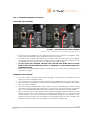
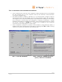
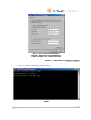
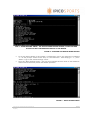
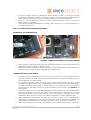
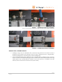
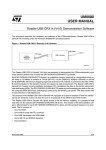
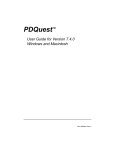
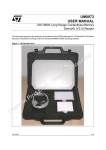
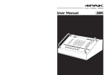
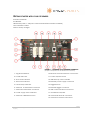
GETTING STARTED WITH YOUR LITE READER
Included materials:
Lite Reader
USB Memory Stick, 1 GB (User’s Manual and referenced files included)
CAT-5 Ethernet Cable
Mascot 3-step charger
FIGURE 1 – DIAGRAM OF LITE READER INTERFACE
(Graphic excerpted from Lite Reader User’s manual)
1. Tag read indicator
10. Ethernet Communications Connection
2. Power indicator
11. Power ON/OFF switch
3. TX-A Level indicator
12. USB Memory stick controller
4. TX-B Level indicator
13. External power supply connector
5. LAN Activity indicator
14. Trigger button
6. Antenna A transmitter connector
15. External trigger connector
7. Antenna B transmitter connector
16. USB communications connector
8. Power supply status indicator
17. Ventilation Fan/Filter
9. Antenna calibration button
18. Antenna B receiver connector
19. Antenna A receiver connector
Lite Reader Getting Started Guide [In
Progress]
1 of 7
STEP 1: LITE READER POWERING/CHARGING
CHARGING THE LITE READER
FIGURE 2 – PLUGGING IN THE 3-STEP CHARGER
(Be sure to twist the connector to lock in place and power the unit)
Plug the 3-step charger into the External Power Supply Connector (diagram #13),
ensuring that unit power switch indicates that the unit is OFF.
The LED on the charger will indicate one of three states by color as the unit charges;
an orange LED color is the lowest charging state, a yellow LED color indicates midcharging state and a green LED color indicates full/stable charge.
DO NOT LEAVE THE CHARGER PLUGGED INTO THE UNIT FOR MORE THAN 12 HOURS
EVEN IF THE CHARGER DOES NOT DISPLAY A GREEN LED, AS THIS WOULD INDICATE A
DAMAGED BATTERY.
When the LED charger light is green, the battery is at a ready state, indicating a full
and stable charge.
POWERING THE LITE READER
The unit is safe to operate while 3-step charger is connected to the External Power
Supply Connector (diagram #13).
To power the unit, switch the Power ON/OFF Switch (diagram #11) to the ON position.
When powered, the reader’s Power Indicator (diagram #2) will turn green, this means
that the unit is powered.
The unit will emit audible beeps when turned on. This is a standard part of the booting
procedure. The beeping will shortly stop. If it does not, this may indicate a problem
with your Lite Reader and IPICO Sports should be contacted about such problems.
When ON, the unit’s Power Supply Status Indicator (diagram #8) will display a visual
representation of the unit’s power. If the needle of the indicator is on the green side
of the spectrum, the unit has a stable and operable charge. If the needle is on the
red end of the spectrum, the unit needs to be charged with the 3-step charger. The
reader’s battery will continue to charge even while it is powered ON.
Lite Reader Getting Started Guide [In
Progress]
2 of 7
STEP 2: CONFIGURING YOUR LITE READER FOR OPERATION
Once powered ON, insert the CAT-5 Ethernet Cable included with the Lite Reader
into the network port on your computer and into the Ethernet Communications
Connection (diagram #10).
The default reader IP address is 192.168.1.101, or in the 192.168.1.* range. In order to
communicate with the Lite Reader over the CAT-5 Ethernet Cable, the IP address
and range on the computer connected to the reader must change as well. Open
your computer’s Control Panel and navigate to “Network Connections,” double
clicking it and finding “Local Area Connection,” also double clicking that icon. Follow
the process indicated in FIGURE 2 to change the IP address of the computer
connected to the reader (figure on next page).
Once completed, attempt to connect to the reader by using Microsoft Telnet, a
program that comes with Windows. Start Telnet by clicking Start
Run
and typing
“Telnet” into the box that appears upon clicking “Run.”
STEP 1 – CLICK ON“PROPERTIES”
Lite Reader Getting Started Guide [In
Progress]
STEP 2 – HIGHLIGHT “INTERNET PROTOCOL
(TCP/IP)” AND CLICK “PROPERTIES”
3 of 7
STEP 3 – CLICK “USE THE FOLLOWING IP
ADDRESS” AND SPECIFY THE ADDRESSES AS
LISTED, CLICKING “OK” TO EXIT AND SAVE
FIGURE 3 – CONFIGURING COMPUTER IP ADDRESS
(Windows XP pictured)
The use of Telnet is detailed in Figure 3 below:
STEP 1 – TYPE “o [IP ADDRESS OF YOUR READER]” (IN THIS CASE 192.168.1.31) AND PRESS
“ENTER”
Lite Reader Getting Started Guide [In
Progress]
4 of 7
STEP 2 – AFTER PRESSING “ENTER,” THE ABOVE SCREEN SHOULD APPEAR, GIVING THE USER
ACCESS TO THE CONFIGURATION DETAILS OF THE READER.
FIGURE 4 – STANDARD LITE READER TELNET SESSION
To set the basic details of the reader’s configuration, key in the selection numbered
“1” at the prompt which reads “Key in Your Selection.” After keying in “1,” press
“Enter” to go to the “Basic Settings” menu.
From the “Basic Settings menu,” the user can change the time zone of the reader as
well as the local time by which the reader operates.
FIGURE 5 – BASIC SETTINGS MENU
Lite Reader Getting Started Guide [In
Progress]
5 of 7
The above figure (Figure 4), details the “Basic Settings” menu. To change the time
zone, Key in selection number “2” and press “Enter.” For all other listed settings, key in
their number or letter in the same way and follow the prompts that appear.
Enter “m” into the selection prompt to return to the Main menu, and “q” to quit the
Telnet session completely.
Once finished setting configuration settings, users can key in “q” as their selection to
end the Telnet session.
STEP 4: CAPTURING DATA THROUGH THE READER
USB MEMORY STICK PREPARATION
FIGURE 6 – INSERTING USB MEMORY STICK INTO READER
When ready to take tag data, insert the USB memory stick into the Lite Reader in the
USB Memory Stick Controller (diagram #12).
When the stick is inserted into the system, the system will beep twice, recognizing the
memory stick, and creating the tag data file, TAGDATA.TXT.
CONNECTING MATS TO THE READER
The IPICO Sports Lite Reader has inputs for two (2) mats, an A transmit channel and
receive channel, and a B transmit channel and receive channel (diagram [A] #19,
#6 and [B] #20, #7, respectively).
To connect the mats, insert the large gray connector into either the TX-A or TX-B
connector (diagram #6 and #7, respectively) and the small connector (resembling a
coaxial connector) into the RX-A or RX-B connector, keeping consistency between
connectors (i.e. use RX-A if mat is in TX-A and RX-B if mat is in TX-B). See FIGURE 5 for
more detail.
These channels have corresponding LED lights located at the left of the reader panel
interface (diagram [A] #3, [B] #4). When connecting mats to these inputs, the LEDs
may become red in color. This indicates that the antenna settings need to be
calibrated. This is done by using the “Calibrate Antenna(s)” switch (diagram #9).
After calibrating the channels, the LEDs should return to green color, indicating that
the reader is calibrated for use with the attached mats. If the LEDs remain red, this
may indicate a problem with the reader, and IPICO Sports should be contacted.
After connecting your mats to the Lite Reader, your reader will be ready to read tags.
Lite Reader Getting Started Guide [In
Progress]
6 of 7
FIGURE 7 – CONNECTING MATS (RX CHANNEL)
(Be sure to twist the RX connector into place as well to ensure a solid connection)
FIGURE 8 – CONNECTING MATS (TX CHANNEL)
READING TAGS / FINISHING SESSION
Holding a tag over an attached mat, lower the tag until the unit starts to emit a
beeping noise rapidly. This indicates that the tag is being read; the “Tag Reader”
indicator (diagram #1) will flash green when reading tags.
Once finished reading tags, hold down the “Trigger” button (diagram #14). Hold the
button until the unit emits a beeping noise four successive times. This prepares the tag
data read by the Lite Reader for analysis. Once this process is complete, the USB
Memory stick can be removed from the system safely.
Lite Reader Getting Started Guide [In
Progress]
7 of 7