1
USER’S GUIDE
Intelligent Picomotor™
Control Modules
Driver, Controllers, I/O Modules,
Joystick, and Hand Terminal
U.S. Patents #5,394,049, #5,410,206
Use of controls or adjustments, or performance of procedures
other than those specified herein may result in exposure to
high voltages.
2584 Junction Ave. • San Jose, CA 95134-1902 • USA
phone: (408) 919-1500 • e-mail: [email protected] • www.newfocus.com
Warranty
New Focus, Inc. guarantees its products to be free of material and workmanship defects for one
year from the date of shipment. This warranty is in lieu of all other guarantees expressed or
implied and does not cover incidental or consequential loss.
Products described in this document are covered by U.S. Patents #5,394,049 and #5,410,206.
Information in this document is subject to change without notice.
Copyright 2003, 2002–1998, New Focus, Inc. All rights reserved.
Picomotor is a trademark, and the
logo and NEW FOCUS, Inc. are trademarks
of NEW FOCUS, Inc. Rabbit 2000 is a trademark of Rabbit Semiconductor. LabVIEW is a
trademark of National Instruments Corporation. Visual Basic and Windows are registered
trademarks of Microsoft Corporation.
Document Number 872209 Rev. C.4
Contents
Introduction
7
Overview . . . . . . . . . . . . . . . . . . . . . . . . . . . . . . . . . . . . . . . . . 7
General Picomotor Concepts . . . . . . . . . . . . . . . . . . . . . 16
Picomotor Products and Accessories . . . . . . . . . . . . . . 18
Software Options . . . . . . . . . . . . . . . . . . . . . . . . . . . . . . . . 21
User Safety. . . . . . . . . . . . . . . . . . . . . . . . . . . . . . . . . . . . . . . 22
Setting Up
23
Overview . . . . . . . . . . . . . . . . . . . . . . . . . . . . . . . . . . . . . . . . 23
Driver Kits with Joystick and/or Hand Terminal . . . . 25
Using MCL with the Network Controller . . . . . . . . . . 26
Using MCL with the Ethernet Controller . . . . . . . . . . . 28
Using MCL with the Ethernet Controller and
Hand Terminal . . . . . . . . . . . . . . . . . . . . . . . . . . . . . . . . . . . 31
Using MCL with a Serial Port and PC, Hand
Terminal, Joystick, and/or Ethernet Controller . . . . . 32
Using DLL/DCN with the Driver(s) Only . . . . . . . . . . . 32
Using DLL/DCN with the Driver(s) and
I/O Module(s) . . . . . . . . . . . . . . . . . . . . . . . . . . . . . . . . . . . . 34
Using DLL/DCN with the Driver(s), I/O Module(s),
and Joystick. . . . . . . . . . . . . . . . . . . . . . . . . . . . . . . . . . . . . . 35
Manual Control: Using the Hand Terminal
or Joystick
37
Overview . . . . . . . . . . . . . . . . . . . . . . . . . . . . . . . . . . . . . . . . 37
Using the Hand Terminal . . . . . . . . . . . . . . . . . . . . . . . . . 37
Using the Joystick . . . . . . . . . . . . . . . . . . . . . . . . . . . . . . . . 39
Intelligent Picomotor™ Control Modules
Contents • 3
Computer Control: Using MCL
45
Overview . . . . . . . . . . . . . . . . . . . . . . . . . . . . . . . . . . . . . . . . 45
Using the RS-232 Interface. . . . . . . . . . . . . . . . . . . . . . . . 45
Using the Ethernet . . . . . . . . . . . . . . . . . . . . . . . . . . . . . . . 48
Using the Hand Terminal . . . . . . . . . . . . . . . . . . . . . . . . . 54
Rules of Operation . . . . . . . . . . . . . . . . . . . . . . . . . . . . . . . 55
Programming for the Network or
Ethernet Controller. . . . . . . . . . . . . . . . . . . . . . . . . . . . . . . 55
Conventions . . . . . . . . . . . . . . . . . . . . . . . . . . . . . . . . . . . . . 57
Command Summary . . . . . . . . . . . . . . . . . . . . . . . . . . . . . 57
Command Definitions. . . . . . . . . . . . . . . . . . . . . . . . . . . . 61
Examples . . . . . . . . . . . . . . . . . . . . . . . . . . . . . . . . . . . . . . . . 99
Computer Control: Using the DCN Interface
101
Overview . . . . . . . . . . . . . . . . . . . . . . . . . . . . . . . . . . . . . . .101
Using the RS-485 Interface. . . . . . . . . . . . . . . . . . . . . . .101
Rules of Operation . . . . . . . . . . . . . . . . . . . . . . . . . . . . . .102
Model 8753 Picomotor Driver Control Panel. . . . . .103
Model 8751-C Closed-Loop Driver Control Panel .108
Joystick Control Panel . . . . . . . . . . . . . . . . . . . . . . . . . .111
I/O Modules Control Panel. . . . . . . . . . . . . . . . . . . . . . .113
Computer Control: Using DLLs
115
Overview . . . . . . . . . . . . . . . . . . . . . . . . . . . . . . . . . . . . . . .115
Using the RS-485 Interface. . . . . . . . . . . . . . . . . . . . . . .116
Using the LabVIEW Interface . . . . . . . . . . . . . . . . . . . .117
Programming for the Driver(s), I/O Module(s),
and Joystick. . . . . . . . . . . . . . . . . . . . . . . . . . . . . . . . . . . . .120
Conventions . . . . . . . . . . . . . . . . . . . . . . . . . . . . . . . . . . . .120
Command Summary . . . . . . . . . . . . . . . . . . . . . . . . . . . .122
Command Definitions. . . . . . . . . . . . . . . . . . . . . . . . . . .125
Example . . . . . . . . . . . . . . . . . . . . . . . . . . . . . . . . . . . . . . . .172
Computer Control: Global Definitions
179
Addressing . . . . . . . . . . . . . . . . . . . . . . . . . . . . . . . . . . . . .179
Intelligent Picomotor Driver . . . . . . . . . . . . . . . . . . . . .180
Closed-Loop Picomotor Driver . . . . . . . . . . . . . . . . . .187
Joystick . . . . . . . . . . . . . . . . . . . . . . . . . . . . . . . . . . . . . . . . .192
4 • Contents
NEW FOCUS, Inc.
Troubleshooting
193
Closed-Loop Picomotor Driver . . . . . . . . . . . . . . . . . . 193
Joystick. . . . . . . . . . . . . . . . . . . . . . . . . . . . . . . . . . . . . . . . . 194
Hand Terminal . . . . . . . . . . . . . . . . . . . . . . . . . . . . . . . . . 196
Network Controller . . . . . . . . . . . . . . . . . . . . . . . . . . . . . 196
Ethernet Controller . . . . . . . . . . . . . . . . . . . . . . . . . . . . . 197
Specifications
199
Model 8753 Intelligent Picomotor Drivers . . . . . . . . 199
Model 8751-C Closed-Loop Picomotor Drivers . . . 203
Model 8750 Intelligent Picomotor
Network Controller . . . . . . . . . . . . . . . . . . . . . . . . . . . . . 208
Model 8752 Intelligent Picomotor
Ethernet Controller . . . . . . . . . . . . . . . . . . . . . . . . . . . . . 213
Model LS-773 Open Collector I/O Module. . . . . . . . 219
Model LS-784 Open Emitter I/O Module . . . . . . . . . 224
Model 8754 Intelligent Picomotor Joystick . . . . . . . 230
Model 8757 Hand Terminal. . . . . . . . . . . . . . . . . . . . . . 233
Driver Kit Power Supply. . . . . . . . . . . . . . . . . . . . . . . . . 234
Models 8301–8341, 8301–8341, and
8351 Picomotors. . . . . . . . . . . . . . . . . . . . . . . . . . . . . . . . 236
Model 8310 Closed-Loop Picomotor . . . . . . . . . . . . . 238
Customer Service
241
Technical Support . . . . . . . . . . . . . . . . . . . . . . . . . . . . . . 241
Service . . . . . . . . . . . . . . . . . . . . . . . . . . . . . . . . . . . . . . . . . 241
Intelligent Picomotor™ Control Modules
•5
6•
NEW FOCUS, Inc.
Introduction
Overview
The Picomotor™ is a motorized actuator designed for applications
requiring a compact, high-resolution positioner. New Focus offers the
Picomotor as a stand-alone actuator as well as integrated into mounts
and stages. The Picomotor has a linear resolution of less than 30 nm for
Standard Picomotors and less than 100 nm for Tiny Picomotors. The
Intelligent Picomotor drivers generate the electronic pulses that
provide open- or closed-loop control of the Picomotors.
The Intelligent Picomotor control modules—including the Model 8753
Intelligent Picomotor Driver, the Model 8751-C Closed-Loop
Picomotor Driver, the Model LS-773 Open Collector Module, the
Model LS-784 Open Emitter I/O Module, the Model 8750 Intelligent
Picomotor Network Controller, the Model 8752 Intelligent Picomotor
Ethernet Controller, the Model 8754 Intelligent Picomotor Joystick, and
the Model 8757 Intelligent Picomotor Hand Terminal—offer a
compact, rugged, and versatile method for controlling New Focus
Picomotors.
Each controller network can contain up to 31 drivers or I/O devices, to
control up to a maximum of 93 picomotors.
The Model 8763-KIT Picomotor driver kits include a controller and a
driver. When supplemented with a joystick or hand terminal, the driver
kit can be used for stand-alone operation.
Figure 1 shows how the components of the Intelligent Picomotor
network can be configured for different motion control applications.
The following sections describe the individual components in detail.
Intelligent Picomotor™ Control Modules
Introduction • 7
Figure 1: How the
components
an Intelligent
Picomotor network
fit together
Driving single axis devices with the iPico control modules
Model 8722
Comm. Adapter
(Null Modem
Cable)
Model 8351
Tiny Picomotor™ Actuator
Model 830X or 8310
Picomotor™ Actuators
Model 8755
Power Supply
Model 8721
10' Comm. Cable
Cable Provided
with Power Supply
Model 8726
6" Power Cable(s)
Model 8754
iPico™ Joystick
Model 8401
Rotary Stage
Model 8752
Model 8724
One or More
Ethernet Controller 5" Comm. Cable(s) Model 8753 and/ or
Model 8751-C
iPico Driver(s)
Model 8723
3' Comm. Cable
Model 8757
iPico™ Handpad
Driving multi-axis devices with the iPico control modules
Model 8722
Comm. Adapter
(Null Modem
Cable)
Model 8755
Power Supply
Model 8721
10' Comm. Cable
Cable Provided
with Power Supply
Model 8726
6" Power Cable(s)
Model 8754
iPico™ Joystick
Model 8752
Model 8724
Model 8753
Ethernet Controller 5" Comm. Cable(s) Intelligent Driver(s)
Model 8809
Motorized Corner Mount
Model 8725
Multi-Axis Adapter
Model 8723
3' Comm. Cable
Model 8757
iPico™ Handpad
8 • Introduction
NEW FOCUS, Inc.
Intelligent Picomotor Drivers
Each Model 8753 Intelligent Picomotor Driver can drive up to three
individual Picomotors, asynchronously, through its three 4-pin
single-channel output ports. (For multi-axis devices that use 6-pin
connectors, such as optical mounts, you will need to use a Model 8725
multi-axis adapter.)
Figure 2:
Model 8753
Intelligent
Picomotor Driver
Each driver is a member of the Distributed Control Network (DCN).
Up to 31 DCN devices can be controlled over a multi-drop full-duplex
RS-485 network. Standard RJ-45 connectors and commercially
available cables are used to connect the drivers into a network. A DLL
library is available free of charge on the New Focus web site to facilitate
the integration of Picomotor Drivers into your custom applications.
Closed-Loop Picomotor Drivers
The Model 8751-C Closed-Loop Driver can drive a single Picomotor
through its 4-pin single channel port. When used with the Model 8310
closed-loop Picomotor actuator, it offers an ideal solution for
applications where closed-loop control and absolute position
calibration is required.
Up to 31 Model 8751-C drivers can be controlled with the Model 8752
network controller, or the driver can be combined with other DCN
modules to create a mixed system of closed- and open-loop control.
Intelligent Picomotor™ Control Modules
Introduction • 9
Figure 3:
Model 8751-C
Closed-Loop Driver
Figure 4: Model
8751-C ClosedLoop Driver with
Model 8310
Closed-Loop
Picomotor
10 • Introduction
NEW FOCUS, Inc.
Intelligent Picomotor Network Controllers
Figure 5:
Model 8750
Intelligent
Picomotor Network
Controller
The Model 8750 Intelligent Picomotor Network Controller can be used
as an interface between a computer and up to 31 Model 8753 drivers
using a standard RS-232 serial interface, or it can be used with the
joystick and Model 8753 drivers for manual control of Picomotors.
Standard RJ-45 connectors and commercially available cables are used
to connect the controller to the drivers and the joystick. The MCL
commands described in the “Computer Control: Using MCL” chapter
beginning on page 45 can be used to integrate the Picomotor Network
Controllers into your custom applications.
Note:
The Model 8750 network controller does not support the Model 8751-C driver.
To create a network with the Model 8751-C driver, you will need to use the Model
8752 Ethernet Controller.
Intelligent Picomotor Ethernet Controller
The Model 8752 Intelligent Picomotor Ethernet Controller can be used
to interface a computer, located anywhere, with up to 31 Model 8753
and/or 8751-C Picomotor drivers using a standard TCP/IP Ethernet or
RS-232 serial interface. It can also be used with the Model 8754 Joystick
or Model 8757 Hand Terminal for manual control of Picomotors. It
allows for both simultaneous operation by multiple users with
multiple ports and operation through a single port.
The Model 8752 Ethernet Controller differs from the Model 8750
Network Controller in two ways: it has an Ethernet communication
Intelligent Picomotor™ Control Modules
Introduction • 11
port, and it has a plug-in port for the Model 8757 Hand Terminal. The
Ethernet port supports dynamic or static IP addressing and telnet
communication.
Figure 6:
Model 8752
Ethernet Controller
Note:
The Model 8752 Ethernet controller needs to have its firmware upgraded to at
least version 1.5.0 to support the Model 8751-C closed loop drivers. The latest
revision can be downloaded from the New Focus web site and installed with a PC
and null-modem cable.
Intelligent Picomotor Hand Terminal
The Model 8757 Intelligent Picomotor Hand Terminal is an ASCII
terminal for use with the Model 8752 Ethernet Controller. It features a
45-key keypad and a liquid crystal alphanumeric display that can show
up to four lines of 20 characters each. The terminal provides both
preprogrammed shortcut keys for simple Picomotor control and a
standard keypad to allow users to type in individual MCL commands.
12 • Introduction
NEW FOCUS, Inc.
Figure 7:
Model 8757
Hand Terminal
Intelligent Picomotor Joysticks
Figure 8:
Model 8754
Intelligent
Picomotor Joystick
The Model 8754 Intelligent Picomotor Joystick is a multifunction I/O
device designed for a wide range of applications. When used with the
Model 8750 network controller, it can control up to three Model 8753
and/or Model 8751-C drivers (nine standard or three closed-loop
Picomotors).
The joystick, like the drivers, is also a member of the DCN, and can be
programmed to control any Picomotor on any driver in the DCN using
the available DLL library.
Intelligent Picomotor™ Control Modules
Introduction • 13
Intelligent Picomotor Driver Kit
Figure 9:
The driver kit
includes an
Ethernet controller,
driver, required
cables, and power
supply
The driver kits provide an out-of-the-box solution for controlling
Picomotors. Each kit includes a Model 8752 Ethernet controller, a
power supply, and one Model 8753 Intelligent Picomotor Driver. The
kits also include mounting bracket(s) and all required cables.
Intelligent Picomotor Open Emitter I/O Module
The Model LS-784 Open Emitter Module is a multifunctional I/O
controller that can be used for a wide range of applications. Designed
as a member of Distributed Control Network (DCN), it can control up
to 31 DCN nodes over a multi-drop full-duplex RS-485 network.
The module supports 10 digital inputs and three analog inputs, and it
provides eight digital “open emitter” outputs capable of sourcing 0.5A.
Features include:
• Three analog inputs, 0-5V, 0-10V, 0-20V, 0-30V (dip-switch
individually selectable), 8-bit precision
• 10 digital inputs
• Eight digital outputs
• Two outputs are PWM-controllable, 8-bit precision
• One input is configurable as counter or timer input with prescaler
14 • Introduction
NEW FOCUS, Inc.
Figure 10: Model
LS-784 Open
Emitter Module
Intelligent Picomotor Open Collector I/O Module
The Model LS-773 Open Collector Module is a multifunctional, I/O
controller designed for a wide range of applications. Up to 31 LS-773
nodes can be controlled over a multi-drop full-duplex RS-485 network.
There are 10 general purpose digital inputs and three analog inputs
with six open collector outputs capable of driving up to1A and one
solid-state relay power source output (5A maximum.).
Features include:
• Three analog inputs, 0-5V, 0-10V, 0-20V, and 0-30V (dip-switch
individually selectable), 8-bit precision
• 10 digital inputs
• Eight digital outputs
• Two outputs are PWM-controllable, 8-bit precision
• One input is configurable as counter or timer input with prescaler
Intelligent Picomotor™ Control Modules
Introduction • 15
Figure 11: Model
LS-773 Open
Collector Module
Intelligent Picomotor Power Cable
The Model 8729 Power Cable is available for the Model LS-773 and
LS-784 I/O Modules. This cable provides a single power supply for the
drivers, controller, and I/O modules.
Figure 12:
Model 8729
Power Cable
General Picomotor Concepts
The key element in our motorized mechanical line is the Picomotor.
The Picomotor’s revolutionary design relies on the principles of static
and dynamic friction. Two jaws grasp an 80-pitch screw, and a
piezoelectric transducer slides the jaws in opposite directions.
16 • Introduction
NEW FOCUS, Inc.
Figure 13:
Schematic of the
action of the
Picomotor
80 Pitch Screw
Two jaws grasp
an 80-pitch screw
Jaws
Piezo
Slow action of
the piezo causes
a screw rotation
Fast action, due
to inertia, causes
no motion
Slow action of the Picomotor (high static friction) causes the screw to
rotate while fast action (low dynamic friction) causes no rotation. By
sending pulses with fast rise times and slow fall times, the piezo will
rotate the screw counter-clockwise. Similarly, sending pulses with slow
rise times and fast fall times rotates the screw clockwise.
Note:
The knob on the end of the drive screw provides inertial mass required for
operation. Removal of the knob will prevent the Picomotor from functioning
properly and void the warranty.
The Picomotor drivers generate the 130-V pulses required to drive the
piezo in the Picomotor.
Step Size and Repeatability
The Picomotor is not a stepper motor. Because it is a friction
mechanism, it does not produce identical steps for each input pulse.
Although the step size can vary slightly from pulse to pulse, it will
always be less than 30 nm for the Standard Picomotor and less than
100 nm for the Tiny Picomotor.
In addition, there will be a significant variance in step size when
starting the motor from a standstill or changing its direction.
Other factors that affect the angle change and linear travel per pulse
include direction of rotation, load, temperature, and life and wear of
the unit.
Intelligent Picomotor™ Control Modules
Introduction • 17
Picomotor Products and Accessories
There are two important adapters you may need for connecting
Picomotor driver modules and motors. The tables below lists the entire
Intelligent Picomotor product family, and all of the communication
and control ports. The Model 8722 Intelligent Picomotor
communication adapter is required for connecting computer RS-232
COM ports to the RS-485 daisy-chained network of the driver modules
(see Figure 19 on page 33). The Model 8725 multi-axis adapter connects
the 4-pin Picomotor driver outputs to the 6-pin cables provided on
multi-axis mount products.
Intelligent Picomotor Modules
Model #
18 • Introduction
Description
Communication and
Control Ports
8750
Intelligent Picomotor Network
Controller
2 x RJ-45 (RS-485)
1 x DB-9M (RS-232)
8751-C
Closed-Loop Picomotor Driver
2 x RJ-45 (RS-485)
1 x HDDB-15F (Encoder)
1 x RJ-22 (Actuator)
8752
Intelligent Picomotor Ethernet
Controller
2 x RJ-45 (RS-485)
1 x RJ-11 (RS-232)
1 x RJ-45 (Ethernet)
1 x DB-9M (RS-232)
8753
Intelligent Picomotor Driver
2 x RJ-45 (RS-485)
3 x RJ-22 (Actuator)
8754
Intelligent Picomotor Joystick
2 x RJ-45 (RS-485)
8757
Intelligent Picomotor Hand Terminal
1 x RJ-11 (RS-232)
LS-773
Open Collector I/O Module
2 x RJ-45 (RS-485)
LS-784
Open Emitter I/O Module
2 x RJ-45 (RS-485)
NEW FOCUS, Inc.
Intelligent Picomotor Kits
Model #
Description
8763-KIT
Model 8752 Intelligent Picomotor Ethernet Controller
Model 8753 Intelligent Picomotor Driver
Model 8755 Driver Kit Power Supply
Model 8760 Driver/Controller Assembly Kit
Intelligent Picomotor Accessories
Model #
Description
Connectors
8721
10’ Intelligent Picomotor communication
cable (RS-232/Ethernet)
2 x RJ-45
8722
Intelligent Picomotor communication
adapter (RS-232/RS-485)
1 x DB-9F
1 x RJ-45
8723
3’ Intelligent Picomotor communication
cable (RS-232/Ethernet)
2 x RJ-45
8724
5" Picomotor communication cable
(RS-232/Ethernet) for daisy chaining
drivers or other DCN compatible
components
2 x RJ-45
8725
Multi-axis adapter (allows use of multi-axis
Picomotor devices with Model 8753 driver)
1 x 6-pin RJ-11
3 x 4-pin RJ-22
8726
6" power cable for daisy chaining DCN
modules
2 x 2-pin MSTB2.5/2-ST-5.08
8727
Power connector for connecting usersupplied power
2-pin MSTB-2.5/
2-ST-5.08
8729
Intelligent Picomotor Power Cable,
Double Pigtail
3 x 2-pin MSTB2.5/2-ST-5.08
8755
Intelligent Picomotor driver kit
power supply
2-pin MSTB-2.5/
2-ST-5.08
8760
Intelligent Picomotor Driver/Controller
Assembly Kit (contains Models 8724 and
8726 with hardware for daisy chaining)
2 x RJ-45
2 x 2-pin MSTB2.5/2-ST-5.08
Intelligent Picomotor™ Control Modules
Introduction • 19
Model #
8761
Description
Intelligent Picomotor Computer Interface
Kit (contains Model 8721 cable and Model
8722 adapter)
Connectors
1 x RJ-45
1 x DB-9F
Picomotors
Model #
Description
Connectors
8301–8341
Standard Picomotor
1 x 4-pin RJ-22
8301v–8341v
Vacuum-Compatible Picomotor
Teflon-insulated
28-gauge wires
8351
Tiny Picomotors
1 x 4-pin RJ-22
8310
Closed-loop Picomotor
1 x 4-pin RJ-22
1 x HDDB-15M
Stages and Positioners
Model #
Description
Connectors
8051
Fiber Positioner
1 x 6-pin RJ-11
8071, 8081, 8082
4- and 5-Axis Stages
2 x 6-pin RJ-11
8095
6-Axis Stage
6 x 4-pin RJ-22
8401
Rotary Stage
1 x 4-pin RJ-22
Optical Mounts
Model #
20 • Introduction
Description
Connectors
8807
Mirror Mount
2 x 4-pin RJ-22
8808–8854
Mirror Mounts
1 x 6-pin RJ-11
888X
Pint-Sized Mounts
2 x 4-pin RJ-22
NEW FOCUS, Inc.
Software Options
As described in the next chapter, the Intelligent Picomotor network can
be set up for manual control using the stand-alone driver kits and hand
terminal or joystick, for computer control, or for a custom
configuration using some combination of both. New Focus offers
several software utilities and applications that can help you create the
appropriate system to suit your motion control needs. These software
options and their requirements are described below.
Distributed Control Network (DCN) Utility
Description: Set-up and diagnostic utility
Type: Stand-aloneWindows-based application
Hardware Supported/Required: Models 8753 and 8751-C driver(s),
Model 8754 joystick, Model 8761 PC Interface Kit
Motion Control Language (MCL)
Description: Set of host commands for accessing the MCL firmware
in the network controller.
Type: Serial port command interpreter that can be accessed using
HyperTerminal/MCC Terminal, LabVIEW, C++, or Visual Basic
Hardware Supported/Required: Model 8750 Network Controller,
Model 8752 Ethernet Controller, Null modem cable, Model 8757 Hand
Terminal
Dynamic Link Library (DLL) Library
Description: Function library file to support custom low-level
programming
Type: Programming library that can be accessed using LabVIEW, C++,
or Visual Basic
Hardware Supported/Required: All Intelligent Picomotor modules,
Model 8761 PC Interface Kit
Intelligent Picomotor™ Control Modules
Introduction • 21
User Safety
Voltages of up to 130 V are accessible inside the driver chassis,
mounts, and Picomotors. Although protection circuits are included,
do not operate the units with the driver or mount covers removed. If the
wire of a mount or Picomotor is frayed, discontinue use and return it
for repair.
22 • Introduction
NEW FOCUS, Inc.
Setting Up
Overview
The Intelligent Picomotor components—including the Models 8753
and 8751-C drivers, the Models LS-773 and LS-784 I/O modules, the
Model 8750 network controller, the Model 8752 Ethernet controller,
the Model 8754 joystick, and the Model 8757 hand terminal—are a part
of a versatile and powerful platform for motion control. Depending
upon your unique application, the Intelligent Picomotor network can
be set up with the network controller, utilizing it’s embedded MCL
firmware for manual or computer control, it can be set up with the
Ethernet controller for control with a hand terminal or computer via
the Ethernet, it can be connected to the serial port of a PC to directly
control the drivers and joystick via DLL functions or the DCN Utility,
or it can be set up using any number of combinations of the above.
Figure 14 gives an overview of the configuration options.
Intelligent Picomotor™ Control Modules
Setting Up • 23
Figure 14: Motion
control using
the Intelligent
Picomotor network
Model 8351
Tiny Picomotor™ Actuator
Model 8754
Joystick
Models 830X or 8310
Picomotor™ Actuators
TCP/IP
Model 8757
iPico Handpad
RS-232
TCP/IP
ETHERNET
Model 8753 or
Model 8751-C
iPico™ Driver
Model 8401
Rotary Stage
A
RS-485
Model 8809
Motorized
Corner Mount
RS-485 DISTRIBUTED CONTROL NETWORK (DCN)
Model 8752
Ethernet Controller
(RS-232 Null
Modem Cable)
RS-485
Model 8754
Joystick
B
Model 8750
Network Controller
(discontinued)
(RS-232 Null
Modem Cable)
Model 8725
Multi-Axis Adapter
Model 8753
iPico™ Driver
LO
GO
SO
L
NET
WO
RK
MAS
TER
CON
TRO
LLE
R LS-7
73
Model LS773
I/O Module
(open collector)
LO
GO
SO
L
NET
WO
RK
MAS
TER
CON
TRO
LLE
R LS-7
84
Model LS784
I/O Module
(open emitter)
FUTURE
PRODUCTS
C
Model 8722
Comm. Adapter
Based on your chosen application, the Intelligent Picomotor network
can be set up for use in one of many ways:
• Manual control using a driver kit and selected interface peripheral
(joystick, hand terminal, computer)
• Computer control using MCL with the network controller
• Computer control using MCL with the Ethernet controller
• Hand terminal control using MCL with the Ethernet controller
• Mixed control using MCL with a Serial Port and PC, hand terminal,
and/or joystick and Ethernet controller
• Computer control using DLL/DCN with the driver(s) only
• Computer control using DLL/DCN with the driver(s) and I/O
module(s)
24 • Setting Up
NEW FOCUS, Inc.
•
•
Computer control using DLL/DCN with the driver(s) and joystick
Computer control using DLL/DCN with the Driver(s) and I/O
Modules
The following sections describe the different set-up methods and the
steps needed to get your system up and running.
Driver Kits with Joystick and/or Hand Terminal
The Model 8763-KIT driver kit, when configured with a joystick or
hand terminal, is an out-of-the-box solution for manual motion
control, or for computer control, with the addition of an optional
Model 8761. The kits come pre-assembled, with the Ethernet controller
and driver mounted together, and include all of the cables and adapters
needed for connecting the controller, driver, and power supply. A
common hardware configuration for the Model 8763-KIT is shown in
Figure 15.
Figure 15:
Model 8763-KIT
with joystick and
mount
The following section takes you through the basic steps for connecting
the components of the kit and a joystick or hand terminal. The controls
and functions are described in the “Manual Control: Using the Hand
Terminal or Joystick” chapter beginning on page 37.
1. Connect the Model 8752 Ethernet Controller’s Network Out port to
the Model 8753 driver’s Network In using a 5" communication
cable (Model 8724).
Intelligent Picomotor™ Control Modules
Setting Up • 25
2. On the last driver or module in any RS-485 network, set the two
terminating resistors’ DIP switches to the “ON” position.
3. If you will be using a Model 8754 Joystick in your set-up:
•
Connect the Ethernet controller’s Joystick port to the joystick’s
Network In using a Model 8723 communication cable.
•
Verify that the joystick’s DIP switches are set to their default
positions: SW1 is “OFF” and SW2 is “ON.”
4. To connect a Model 8757 Hand Terminal, plug it into the Hand
Terminal port using the cable provided with the hand terminal.
5. Connect the controller’s power supply connector to the driver’s
power connector using the Model 8726 power supply cable. Be
sure to place the power supply cable connector into the right two
pins in the driver.
6. Connect the controller’s Ethernet port to your network using a
standard Category 5 cable.
Using MCL with the Network Controller
The MCL firmware for the New Focus network controller contains a
simple but powerful set of host commands that can be used to
integrate the network controllers into your custom applications. The
MCL commands are described in the “Computer Control: Using MCL”
chapter beginning on page 45.
To access the MCL commands, set up your network as described below.
Then, using a standard DB-9 NULL-Modem RS-232 cable, connect the
COM port of your host computer to the Computer connector on the
network controller. The baud rate should be set to 19200; there are
eight data bits, one stop bit, and no parity.
Figure 16 shows the hardware configuration for using MCL with the
network controller.
26 • Setting Up
NEW FOCUS, Inc.
Figure 16:
Hardware
configuration for
using MCL with the
Network Controller
The following section takes you through the basic steps for setting up a
system with the Model 8750 Network Controller.
1. Connect the network controller’s Network Out port to the Model
8753 driver’s Network In using a 5" communication cable (Model
8724).
2. If you are using more than one driver, connect the Network Out
from the first driver to the Network In on the next driver using
another 5" communication cable.
3. Repeat Step 2 for all remaining drivers.
Note:
4. If you are using LS-773 or LS -784 I/O module(s) in your set-up,
connect the Network In from the first I/0 module to the Network
Out on the last driver (see Figure 20).
I/O modules must be connected to the end of the daisy chain of devices, after
the drivers.
5. For the last driver or I/O module on the network, set the two
terminating resistors’ DIP switches to the “ON” position.
6. If you are using a joystick in your setup:
Intelligent Picomotor™ Control Modules
Setting Up • 27
•
Connect the network controller’s Joystick port to the joystick’s
Network In using a Model 8723 communication cable.
The joystick can actually be hooked up to either network port on the
controller, not just the Joystick port.
•
Verify that the joystick’s DIP switches are set to their default
positions: SW1 is “OFF” and SW2 is “ON.”
Note:
7. Connect the controller’s power supply connector to the first
driver’s power connector using the Model 8726 power supply
cable. Be sure to place the power supply cable connector into the
right two pins in the driver.
8. If you are using more than one driver, use the additional Model
8726 power cables to connect power. Align the cables such that the
connected pins from the adjacent drivers match, i.e., if the cable
comes from the right pins it plugs in to the right pins of the next
driver, then the next cable goes out from the left pins and plugs
into the left pins of the next connector, and so on (see Figure 16).
9. If you are using I/O modules in your setup, place the center
terminal of the 8729 split power cable into the driver adjacent to
the I/O module. Connect one end of the cable to the I/O module
power input pins 1 and 2. Connect the other end to the next driver
in the stack or to the network controller if this is the only driver.
Note:
10. Connect the power supply to the remaining power input on the last
driver in the chain (i.e., the driver furthest away from the
controller).
Each power supply supports up to three drivers. If you have more than three
drivers in your installation, you will need to hook in additional power.
Using MCL with the Ethernet Controller
The Model 8752 Intelligent Picomotor Ethernet Controller can be used
to interface a computer with up to 31 drivers and/or I/O modules using
a standard TCP/IP Ethernet interface. It can also be set up for use with
the Model 8757 Hand Terminal and Model 8754 Joystick, or for
computer control using the RS-232 serial interface, as described in the
“Using MCL with the Ethernet Controller and Hand Terminal” and
28 • Setting Up
NEW FOCUS, Inc.
“Using MCL with a Serial Port and PC, Hand Terminal, Joystick, and/or
Ethernet Controller” sections below.
Figure 17 shows the various set-up connections available when using
MCL with the Ethernet controller.
Figure 17: Model
8752 Ethernet
Controller with
set-up connections
Network Out
to Driver
Joystick
Connection
Hand Terminal
Connection
Ethernet
Connection
Computer
Connection
Power Supply
The following section takes you through the basic steps for setting up a
system with the Model 8752 Ethernet Controller. The controls and
functions are described in the “Computer Control: Using MCL” chapter
beginning on page 45.
1. Connect the Model 8752 Ethernet Controller’s Network Out port to
a Model 8753 or Model 8751-C driver’s Network In using a 5" communication cable (Model 8724).
2. If you are using more than one driver, connect the Network Out
from the first driver to the Network In on the next driver using
another 5" communication cable.
3. Repeat Step 2 for all remaining drivers.
Intelligent Picomotor™ Control Modules
Setting Up • 29
Note:
4. If you are using LS-773 or LS -784 I/O module(s) in your set-up,
connect the Network In from the first I/0 module to the Network
Out on the last driver (see Figure 20).
I/O modules must be connected to the end of the daisy chain of devices, after
the drivers.
5. For the last driver or I/O module on the network, set the two
terminating resistors’ DIP switches to the “ON” position.
6. If you will be using a Model 8754 Joystick in your set-up:
•
Connect the Ethernet controller’s Joystick port to the joystick’s
Network In using a Model 8723 communication cable.
•
Verify that the joystick’s DIP switches are set to their default
positions: SW1 is “OFF” and SW2 is “ON.”
7. Connect the controller’s power supply connector to the first
driver’s power connector using the Model 8726 power supply
cable. Be sure to place the power supply cable connector into the
right two pins in the driver.
8. If you are using more than one driver, use the additional Model
8726 power cables to connect power. Align the cables such that the
connected pins from the adjacent drivers match, i.e., if the cable
comes from the right pins it plugs in to the right pins of the next
driver, then the next cable goes out from the left pins and plugs
into the left pins of the next connector, and so on (see Figure 17).
Note:
9. Connect the power supply to the remaining power input on the last
driver in the chain (i.e., the driver furthest away from the
controller).
Each power supply supports up to three drivers. If you have more than three
drivers in your installation, you will need to hook in additional power.
10. If you are using I/O modules in your setup, place the center
terminal of the 8729 split power cable into the driver adjacent to
the I/O module. Connect one end of the cable to the I/O module
power input pins 1 and 2. Connect the other end to the next driver
in the stack or to the network controller if this is the only driver.
30 • Setting Up
NEW FOCUS, Inc.
Note:
11. Connect the controller’s Ethernet port to your network using a
standard Category 5 cable.
Ethernet configuration and communication options are described in detail in
the “Using the Ethernet” section beginning on page 48.
Using MCL with the Ethernet Controller and
Hand Terminal
The Model 8757 Hand Terminal provides additional manual control
capabilities to the Intelligent Picomotor system—it can control up to
31 drivers, compared to just three drivers with the joystick. The
controls and functions are described in the “Manual Control: Using the
Hand Terminal or Joystick” chapter beginning on page 37.
Note:
To using a hand terminal for manual control, set up your network as
described in the “Using MCL with the Ethernet Controller” section
above. Then, simply connect the hand controller to the Hand Terminal
port using the cable provided with the hand terminal.
The hand terminal can be hot-plugged into the network and used immediately.
Figure 18 shows a typical hardware configuration using the hand
terminal.
Figure 18: Model
8757 Hand Terminal
connected to
Model 8752 Ethernet
Controller
Hand Terminal
Cable
Ethernet Controller
Hand Terminal
Intelligent Picomotor™ Control Modules
Setting Up • 31
Using MCL with a Serial Port and PC, Hand Terminal,
Joystick, and/or Ethernet Controller
The Intelligent Picomotor drivers and I/O modules can be controlled in
any number of ways: with a joystick, a hand terminal, an Ethernet
controller connected through Ethernet, a PC connected to the serial
port, or a combination of two these methods simultaneously. For
example, while directing a device with the hand terminal, you can use a
PC connected to a serial port to monitor the motion its motion.
To set up your network for multiple methods of control using the
Ethernet Controller, follow the steps described in “Using MCL with the
Ethernet Controller” (and “Using MCL with the Ethernet Controller and
Hand Terminal” if you are using a hand terminal). Then, using a
standard DB-9 NULL-Modem RS-232 cable, connect the COM port of
your host computer to the Computer connector on the network
controller. The baud rate should be set to 19200; there are eight data
bits, one stop bit, and no parity.
Figure 17 shows the possible set-up connections for using MCL with
the Ethernet controller.
Using DLL/DCN with the Driver(s) Only
For computer control of the drivers using the available DLL library
(page 115) or DCN Utility (page 101), you will need to build your
system without using the network or Ethernet controllers. The
hardware configuration is shown in Figure 19.
32 • Setting Up
NEW FOCUS, Inc.
Figure 19:
Hardware
configuration for
using DLL/DCN
with driver(s) Only
Note:
1. Use the Model 8761 Computer Interface Kit to connect the
Network In port of the driver to the computer’s COM port.
2. If you are using more than one driver, connect the Network Out
port of the first driver to the Network In on the next driver using
the Model 8724 communication cable.
3. Repeat Step 2 for all remaining drivers.
4. For the last driver on the network, set the two termination
resistors’ DIP switches to the “ON” position.
5. Connect the Model 8755 power supply to the driver’s power connector.
6. If you are using more than one driver, connect the power supply to
the last driver on the network and daisy chain adjacent drivers with
the Model 8726 power cable. Align the cables such that the
connected pins from the adjacent drivers match, i.e., if the cable
comes from the right pins it plugs in to the right pins of the next
driver, then the next cable goes out from the left pins and plugs
into the left pins of the next connector, and so on (see Figure 19).
Each power supply supports up to three drivers. If you have more than three
drivers in your installation, you will need to hook in additional power.
Intelligent Picomotor™ Control Modules
Setting Up • 33
Using DLL/DCN with the Driver(s) and I/O Module(s)
To set up for computer control of the driver and I/O modules using the
available DLL library (page 115) or DCN Utility (page 101), follow
steps 1–3 in the “Using DLL/DCN with the Driver(s) Only” section
above. Then take the following steps:
Note:
1. Connect the Network In from the first I/0 module to the Network
Out on the last driver.
I/O modules must be connected to the end of the daisy chain of devices, after
the drivers.
2. For the last I/O module on the network, set the two terminating
resistors’ DIP switches to the “ON” position.
3. Place the center terminal of the 8729 split power cable into the
driver adjacent to the I/O module. Connect one end of the cable to
the I/O module power input pins 1 and 2. Connect the other end to
the next driver in the stack.
The hardware configuration is shown in Figure 20.
Figure 20: Model
LS-773 or LS-784
connected to
iPico drivers
Drivers
Network Connection
of I/O Module to Driver
34 • Setting Up
I/O Module
Double Pigtail
Power Cord
Power Supply
NEW FOCUS, Inc.
Using DLL/DCN with the Driver(s), I/O Module(s), and
Joystick
The DLL library (page 115) and DCN Utility (page 101) also include
commands for the joystick. To utilize them, you will need to build your
system without using a network controller. The hardware
configuration is shown in Figure 21.
Figure 21:
Hardware
Configuration for
Using DLL/DCN
with Driver(s) and
Joystick
1. Set the DIP switches on the joystick as follows: SW1 is “ON” and
SW2 is “OFF.”
2. Use the Model 8761 computer interface kit to connect the
Network In port of the joystick to the computer’s COM port.
3. Connect the Network Out port of the joystick to the Network In
port of the driver using a Model 8723 communication cable.
4. If you are using more than one driver, connect the Network Out
port of the first driver to the Network In on the next driver using
the Model 8724 communication cable.
5. Repeat Step 2 for all remaining drivers.
Intelligent Picomotor™ Control Modules
Setting Up • 35
Note:
6. If you are using LS-773 or LS -784 I/O module(s) in your set-up,
connect the Network In from the first I/0 module to the Network
Out on the last driver (see Figure 20).
I/O modules must be connected to the end of the daisy chain of devices, after
the drivers.
7. For the last driver or I/O module on the network, set the two
termination resistors’ DIP switches to the “ON” position.
8. Connect the Model 8755 power supply to the power connector on
the driver.
9. If you are using more than one driver, connect the power supply to
the last driver on the network and daisy chain adjacent drivers with
the Model 8726 power cable. Align the cables such that the
connected pins from the adjacent drivers match, i.e., if the cable
comes from the right pins it plugs in to the right pins of the next
driver, then the next cable goes out from the left pins and plugs
into the left pins of the next connector, and so on (see Figure 21).
Note:
36 • Setting Up
10. If you are using I/O modules in your setup, place the center
terminal of the 8729 split power cable into the driver adjacent to
the I/O module. Connect one end of the cable to the I/O module
power input pins 1 and 2. Connect the other end to the next driver
in the stack.
Each power supply supports up to three drivers. If you have more than three
drivers in your installation, you will need to hook in additional power.
NEW FOCUS, Inc.
Manual Control: Using the Hand
Terminal or Joystick
Overview
The Model 8757 hand terminal and Model 8754 joystick offer two
alternatives for manual control of a Picomotor network.
The joystick, when used with the Model 8750 network controller, can
control up to three Model 8753 and/or Model 8751-C drivers (nine
standard or three closed-loop Picomotors).
The hand terminal, an ASCII terminal for use with the Model 8752
Ethernet Controller, offers even greater control functionality. The
terminal provides preprogrammed shortcut keys for simple Picomotor
control, or users can type in individual MCL commands directly using
its standard keypad and alphanumeric display.
Using the Hand Terminal
Display
The Model 8757 Hand Terminal has a 45-key keypad for executing
commands, programming, or local control of the Picomotors with
shortcut keys. The first row of the LCD display shows the status of the
network components (see Status Indicators section below). The second
line is used as a “command line” to display the command typed by the
user or selected from the shortcut keys. The third and fourth lines show
the response from the controller.
Intelligent Picomotor™ Control Modules
Manual Control: Using the Hand Terminal or Joy-
Status Indicators
•
•
•
•
•
•
•
•
HH: The hand terminal is active.
DRV=x: The hand terminal has selected driver x for control.
MOT=y: The hand terminal has selected motor y for control.
S/s: The selected motor is a closed-loop motor and is in closedloop mode/open-loop mode (toggle with SER/NOS shortcut key).
J/j: The joystick is active/inactive (toggle with JOF/JON shortcut key).
C/F/U: The selected axis is set to coarse speed/fine speed/userdefined speed.
T/t: A telnet session is active/inactive.
MAP: The joystick is active and is remapped according to the list of
joystick axes corresponding to listed drivers.
Shortcut Keys
The hand terminal features shortcut keys which allow the user to
perform preprogrammed functions without the need to key in a series
of MCL commands. Each key is assigned two functions, as printed in
white and yellow on the button. A single key press will perform the
function printed in white; pressing the Shift key then the key will
command the function in yellow.
Note:
The shortcut keys are applicable to one axis only (the currently selected driver and
channel).
The shortcut keys and their functions are as follows:
• Steps—Defines the number of pulses sent to the selected channel
when a +/- Step is invoked. The default value is 1. Press Shift then
Step keys to activate.
• Hi/Lo—Toggles between Coarse (2000 Hz) and Fine (250 Hz)
speeds. The default setting is Fine. Press Shift then Hi/Lo key to
activate.
• +Jog—Sends continuous positive step count to the selected axis at
the selected Velocity as long as button is pressed. The motion mode
is Velocity mode.
• –Jog—Sends continuous negative step count to the selected axis at
the selected Velocity as long as button is pressed. The motion mode
is Velocity mode.
38 • Manual Control: Using the Hand Terminal or Joystick
NEW FOCUS, Inc.
•
•
•
•
•
•
•
•
SER/NOS—Toggles open-loop/closed-loop control mode of active
8751-C driver (displayed as s or S on status line). Press Shift then
+Step to activate.
+Step—Sends X positive steps to the selected axis at the selected
speed. The motion mode is Position mode.
–Step—Sends X positive steps to the selected axis at the selected
speed. The motion mode is Position mode.
Stop—Aborts current motion (stop abruptly).
Driver—Selects which drive module is associated with the shortcut
keys. To activate, press this key followed by a number indicating
the address of the drive module, and then press Enter to complete
the command.
Motor—Selects which motor channel is associated with the
shortcut keys. This will toggle between the three motor channels;
the user will not need to type in a number to select the channel. In
addition, this command will automatically enable the driver
amplifier. If the user presses this key again to toggle to another
channel, the amplifier will be disabled, the channel changed, and
then the amplifier re-enabled.
Jof/Jon—Enables/disables the joystick (toggle). Press Shift then Jof/
Jon key to activate.
Speed—This lets the user set a specific speed, if a speed different
than that set with the Coarse/Fine speed toggle. Press Speed, enter
a number indicating the speed (in Hz), then press Enter to complete
the command.
Using the Joystick
Control Modes
The network controller contains firmware that allows you to control
the Picomotor drivers in three modes:
• Stand-alone mode: The joystick controls the motors on up to
three drivers.
• Edit mode: The joystick controls the motors on up to three
drivers, selected from the entire network of up to 31 drivers, with
Intelligent Picomotor™ Control Modules
Manual Control: Using the Hand Terminal or Joy-
•
additional parameters edited using the MCL computer interface
(see page 45).
Command mode: The joystick is disabled, and the MCL computer
interface controls the motors on up to 31 drivers (see page 45).
When the network is switched to command mode, all of the LEDs
on the joystick will be illuminated.
Rules of Operation
When setting up and using the joystick, it is important to note the
following:
• A peripheral device, either joystick, hand terminal, or computer,
must be present at power-up for the network controller to
function. An LED will flash on the network controller to indicate
when there is no properly connected peripheral.
• Once the network is initialized, the joystick can be unplugged and
replugged into the network. Note that when the joystick is
replugged into the network, it does a reset, loads saved values, and
goes into stand-alone mode automatically.
• The network controller has a battery backed-up RAM which is
normally enabled (see “Network Controller DIP Switches” on
page 210.) This allows the joystick settings (I/O states) to stay in
memory when the system is powered off.
• Drivers can also be unplugged and replugged into the network,
but the driver and channel settings are set to default whenever
this is done. The network should be reset after adding or removing
a driver.
• The joystick can only control three of the 31 possible drivers in a
system with one controller. By default, the joystick will only be able
to access only the first three drivers in the network. However, the
joystick can be set to operate any three drivers in the network using
the Map command under computer control (see “Computer Control:
Using MCL” on page 45).
• Changes made to parameters in edit mode stay current until a
power cycle or initialization reloads the “saved” values. To make
any change permanent, parameters must be saved (page 65).
• The default control mode after power-up or reset is stand-alone.
40 • Manual Control: Using the Hand Terminal or Joystick
NEW FOCUS, Inc.
•
•
•
The joystick has four buttons that can be used, in various combinations, to manually control the network functions (see Figure 22):
•
Set Axis Enable (Button 0)
•
Driver (Button 1)
•
Motor (Button 2)
• X+Y Enable (Button 3)
Pressing the Set/Axis Enable, Driver, and Motor buttons on the joystick
will reset the network and load the saved parameters. This will work
even when the joystick is turned off by a JOF MCL command.
Pressing the Set/Axis Enable, Motor, and X+Y/Enable buttons on the
joystick will reset the network and load the default parameters. This
will work even when the joystick is turned off by a JOF MCL command.
Selecting the Motors to Control
Figure 22:
Top view of Model
8754 joystick
NETWORK OUT
NETWORK IN
SET X
SET Y
DRIVER 1
MOTOR A
DRIVER 2
MOTOR B
W W W. N E W F O C U S. C O M
DRIVER 3
MOTOR C
RESERVED
SW 1
SW 2
on
DIP SW
X+Y
ENABLE
(BUTTON 3)
SET AXIS / ENABLE
(BUTTON 0)
DRIVER
(BUTTON 1)
MOTOR
(BUTTON 2)
MODEL 8754 PICOMOTOR JOYSTICK
The Model 8754 is a two-axis joystick that can control up to nine
Picomotors. By default, the X axis and Y axis will be set to the first and
second motor ports on Driver 1. Use the buttons on the joystick to
change the assignment of motors to the X axis and Y axis of the joystick.
1. Press the Set Axis/Enable button to select which axis you want to
change. The Set X and Set Y LEDs at the top of the joystick will indicate which axis is open for programming.
Intelligent Picomotor™ Control Modules
Manual Control: Using the Hand Terminal or Joy-
You can prevent accidental changes to joystick settings by pressing
Set Axis/Enable until the Set X and Set Y LEDs blink alternately. In
this locked state, the X and Y axis maps are displayed in alternation.
2. Press the Driver button to select a driver for the axis. The Driver 1,
Driver 2, and Driver 3 LEDs will indicate the active driver.
The driver numbers represent the order in which the drivers are
connected to the Network Controller, with Driver 1 being the one
directly connected to the controller.
The driver map can be changed to allow the joystick to control any
driver in the network through the MAP command in MCL.
3. Press the Motor button to assign a different motor of the selected
driver to the axis. The Motor A, Motor B, and Motor C LEDs will
indicate the selected axis. You will not be able to assign the same
driver and motor to both the X and Y axes of the joystick. If the
selected driver is an 8751-C closed-loop driver, the selections
Motor B and Motor C are disabled.
To disable an axis, press the Motor button until all three motor
LEDs are off.
By default, the network controller firmware is set to control Standard Picomotors.
If you have selected any Tiny Picomotors to control, you must change the motor
type settings using MCL commands (see “Set Motor Type” on page 86) before
using the joystick. A Picomotor can be damaged if it is driven with the wrong type
of driver signal for an extended period of time, so it is important to ensure that the
motor driver is configured to generate the correct driver signals.
Controlling Picomotors
Once you have assigned motors to the joystick, moving the joystick
handle will run the selected motors.
• For the X axis, moving the joystick left of center will move the
Picomotor counter-clockwise or backwards; right of center results
in clockwise or forward motion.
• For the Y axis, moving the joystick above center will move the
Picomotor clockwise or forward; below center results in counterclockwise or backward motion.
42 • Manual Control: Using the Hand Terminal or Joystick
NEW FOCUS, Inc.
Fine/Coarse Speed
The joystick provides the user with two speed ranges: “coarse speed,”
with a speed range of 8 Hz to 2000 Hz, and “fine speed,” with a speed
range of 1 Hz to 250 Hz. In addition, both the “coarse speed” and the
“fine speed” ranges will have logarithmic responses.
The speed setting will affect both active channels (X and Y) on the
joystick and will also be saved so that the user-selected range is retained
during a power cycle. The default setting for the joystick is “coarse
speed.” The fine/coarse adjustment can be done from the joystick by
pressing the Driver and X+Y Enable buttons (if joystick is not locked out
and/or in axis-selection mode).
Setting Velocity and Acceleration Parameters
Using the Motion Control Language (MCL), you can set parameters that
will allow better control over your motorized devices. Although the
drivers support a maximum speed of 2 kHz, you can use MCL to set
minimum velocity, maximum velocity, and acceleration—see
“Computer Control: Using MCL” on page 45. The joystick will
automatically use these settings.
For example, to reconfigure the joystick for “extra fine” speed control
(e.g., 1 Hz to 10 Hz), the velocity of the particular channel needs to be
changed and saved (to make the change permanent). See the MCL
“Example 3” on page 100.
You can use the joystick to reset the velocity, acceleration, and speed
factor parameters:
• Press the Set Axis/Enable, Driver, and Motor buttons
simultaneously to revert to the last saved parameters.
• Press the Set Axis/Enable, Driver, and X+Y/Enable buttons
simultaneously to revert to the factory default parameters
(maximum velocity = 2 kHz, minimum velocity = 8 Hz, and
acceleration = 8 steps/s2).
Moving Two Motors Simultaneously
Although each driver can only drive one Picomotor at a time, the
joystick does support driving two Picomotors simultaneously, as long
as they are attached to different drivers.
Intelligent Picomotor™ Control Modules
Manual Control: Using the Hand Terminal or Joy-
1. Assign the X axis and Y axis of the joystick to Picomotors on different drivers. (See “Selecting the Motors to Control” on page 41.)
2. Press and hold the X+Y/Enable button on top of the joystick to
move the two motors simultaneously.
3. Release the X+Y/Enable button to move just one axis.
Enabling/Disabling the Joystick
You can disable the joystick to prevent accidentally changing the position
of Picomotors or of joystick settings. To enable or disable the joystick:
1. Press and hold the Set Axis/Enable button. While this button is held
down, moving the joystick will not move any Picomotors.
2. Press and release the X+Y/Enable button on the top of the joystick.
3. Release the Set Axis/Enable button.
4. While the joystick is disabled, all three driver LEDs will be
illuminated on the joystick.
Communications Lock-out
Because the Model 8750 network controllers and Model 8752 Ethernet
controllers accept input from multiple sources, it can be important to
lock out unwanted communication ports.When lock/unlock from
joystick is engaged, communication from all the other ports (PC serial,
handpad serial, and Ethernet) on the controller will be disabled, and the
controller will only respond to commands from the joystick. The hand
terminal displays a message Locked or Unlocked, and input of
commands from the terminal is suspended or resumed, respectively.
Serial console and Telnet sessions will still accept commands, but they
will return an error LOCKED when commands are submitted.
The lock-out from the joystick is achieved by pressing the Motor and
X+Y Enable buttons (if joystick is not locked out and/or in axisselection mode). Pressing the Motor and X+Y Enable buttons again will
toggle the mode, and communication from all other ports will be
enabled. The default mode is with all ports enabled.
44 • Manual Control: Using the Hand Terminal or Joystick
NEW FOCUS, Inc.
Computer Control: Using MCL
Overview
The MCL firmware for the New Focus Model 8750 Network Controller
and Model 8752 Ethernet Controller contains a simple but powerful set
of host commands. The network controller firmware supports up to 31
Picomotor drivers and a joystick; it can be controlled either manually
with the joystick or through MCL with a computer connected to the
serial port. The Ethernet controller supports up to 31 drivers and/or
I/O modules, a joystick, and a hand terminal; it can be controlled
manually with the joystick or hand terminal or through MCL with the
hand terminal or a computer connected via the serial port or Ethernet.
The communication protocol is strictly master-slave protocol—the
host sends a command to the controller and receives the answer. An
answer can be either success or failure.
Both controllers maintain two sets of operational parameters—default
parameters and non-volatile (Flash) parameters. On power up, the
firmware will load the Flash parameters. MCL lets you override the
existing firmware or save new values for various parameters.
Using the RS-232 Interface
The host computer can communicate serially with both the network
controller and the Ethernet controller using a standard DB-9 NULLModem RS-232 cable connected to the Computer connector on the
controller. The baud rate should be set to 19200; there are eight data
bits, one stop bit, and no parity.
Intelligent Picomotor™ Control Modules
Computer Control: Using MCL • 45
Note:
The first driver should be connected to the Network Out connector. The
I/O modules should be connected to the last driver in the daisy chain.
The joystick should be connected to the Joystick connector.
See “Using MCL with the Network Controller” on page 26 or “Using MCL with
the Ethernet Controller” on page 28 for hardware set-up instructions.
Software Set-Up
MCL commands can be sent to the controller either by using a standard
Windows Hyperterminal and manually typing in individual
commands or by using custom programs like LabVIEW™, C/C++, or
Visual Basic® to send sequences of commands.
Hyperterminal Settings
To set up Windows Hyperterminal for communication with the
controller, you will need to take the following steps:
1. Open a Hyperterminal session.
2. Under the File menu, select Properties.
3. In the Connect To tab, select the proper serial port from the
“Connect using” list box.
4. Click the Configure button and set the following parameters:
Bits per second
Data bits
Parity
Stop Bits
Flow control
19200
8
NONE
1
NONE
5. Close the Port settings window by clicking OK.
6.
Select the Settings tab.
7. Verify the following settings:
Emulation
AUTODETECT
Backscroll buffer lines 500
8. Click the ASCII Setup button.
9. Set the following parameters:
Echo typed characters locally
Append line feeds to incoming line ends
46 • Computer Control: Using MCL
NEW FOCUS, Inc.
All other check boxes should not be selected.
10. Close the ASCII Setup window by clicking OK.
11. Close the Properties window by clicking OK.
Note:
You may experience problems with line feeds in some versions of Hyperterminal.
Alternate software is available by download from the New Focus website; see the
Network Controller Terminal section below.
Network Controller Terminal
A stand-alone program for communicating with the MCL firmware,
called Network Controller Terminal, can be downloaded from the New
Focus web site. Network Controller Terminal functions like a Windows
Hyperterminal and can be used to send individual MCL commands via
a serial port to the network controller or Ethernet controller.
To use Network Controller Terminal:
1. Hook up the network controller or Ethernet controller to the COM
port of your PC using a NULL-modem cable.
2. Start the Network Controller Terminal program.
3. Verify the “COM port” setting matches the hardware connection.
“COM1” is the default setting.
4. Press the Initialize button. If initialization is successful, the
“Command” text field will change from gray (inactive) to white (active).
If initialization is not successful, check that your hardware
connections, cable type, and COM port settings are correct. See
“Using MCL with the Network Controller” on page 26 for more
information.
5. To use the software, type commands into the “Command” text field
and press Send. Responses will appear in the “Terminal window.”
Intelligent Picomotor™ Control Modules
Computer Control: Using MCL • 47
Using the Ethernet
Ethernet Communication Options
The Model 8752 Ethernet Controller offers fully integrated 10Base-T
Ethernet connectivity over TCP protocol. Dynamic Host Configuration
Protocol (DHCP) and Domain Name Service (DNS) are supported
configuration options, and Telnet and HTTP are supported application
protocols (other protocols including FTP, SMTP, etc. are not
implemented). MCL commands can be sent through TCP/IP using
standard Telnet client communication.
TCP/IP Communication Applications
TCP/IP-based communication, using MCL commands, can be initiated
in several ways:
•
Using a standard Windows® Telnet Terminal client.
•
Using programming environments such as C/C++, Visual Basic ®,
LabVIEW™, etc. and using TCP Port 23 to establish a Telnet client
interface.
Ethernet Configuration Options
The Model 8752 Ethernet Controller can be configured in a variety of
standard ways, depending upon the network environment available:
• Default configuration: The default factory-set Ethernet
configuration uses DHCP to establish current TCP/IP parameters
upon power-up or reset. The default host name is NF8752-xxxxxx,
where “xxxxxx” is the last three bytes of the unique Media Access
Control (MAC) address of the controller. As such, the default host
name is always unique, and the controller can get different network
configuration parameters (IP address, network mask, gateway, and
name-server addresses) from a DHCP server on the user’s network
each time it powers-up or resets. This is the recommended option
for users who have networks with DHCP and Dynamic DNS
(DDNS) servers.
48 • Computer Control: Using MCL
NEW FOCUS, Inc.
•
•
Custom DHCP configuration with reserved IP address: To
circumvent the problem of getting different IP addresses from the
DHCP server, a specific IP address linked to the controller’s MAC
address can be reserved within the DHCP server on the user’s
network by the network administrator. This will ensure that the
controller gets assigned the same IP address every time. This is the
recommended option for users who have networks with DHCP
servers, but no DDNS servers.
Custom static configuration: Users can also choose to manually
assign a fixed IP address to the controller. However, in order to
avoid network conflicts, the fixed IP address needs to be blocked
from being assigned to other network devices by the network
administrator. In addition to the IP address, the IPMode, Default
Gateway, and Netmask also need to be manually configured.
Activating Configuration Changes
If any of the network parameters are changed, they must be SAVed to
the non-volatile memory and the controller restarted in order for the
settings to come into effect. The network settings can be changed from
any of the three ports—computer, hand terminal, or Ethernet.
Name Resolution
For name resolution requests from clients, it is the network
administrator’s responsibility to ensure that the host name and IP
address of the controller are registered, either automatically with a
DDNS server or manually with a Static DNS server, if either one of
these exist on the user’s network. It is also possible to implement name
resolution locally on a single computer using the standard Windows
“hosts” (or equivalent) file.
Reverting Back to Factory Default Configuration
If any network configuration changes cause the Ethernet connectivity
of the controller to stop functioning, the user can revert back to the
factory default IP configuration by flipping up DIP Switch #1 and doing
a reset using the Set/Axis Enable, Motor and X+Y Enable buttons on the
joystick. After the initialization is complete, turn back down DIP
Intelligent Picomotor™ Control Modules
Computer Control: Using MCL • 49
Switch #1 and execute a SAV command to save the network
configuration parameters to NVRAM.
Ethernet Configuration Examples
Ethernet Configuration Example 1
The Ethernet controller is to be used with the default configuration in a
network that has a DHCP server but no DNS server.
To initiate TCP/IP based communication with the controller, the user
will need take the following steps:
1. Power-up the controller. It will auto-configure itself with DHCP
and default host name.
2. Send an IPADDR MCL command serially via the hand terminal or
computer port to get the current IP address of the controller.
3. Confirm that the Ethernet connection is working by doing one or
more of the following:
•
Type Ping <ipaddr> at the MS-DOS prompt from a
workstation connected to the same network as controller.
•
Open up a browser (Internet Explorer or Netscape) and type in
<ipaddr> to access the web page. Verify the current network
configuration displayed on the web page.
•
Type Telnet <ipaddr> at the MS-DOS prompt.
Ethernet Configuration Example 2
The Ethernet controller is to be used with the default configuration in a
network with DHCP and DDNS servers (e.g. Win2000 Server).
However, the host name needs to be changed to NF8752-001.
The user will need to go through the following steps:
1. Power-up the controller. It will auto-configure itself with DHCP
and default host name.
2. Change the host name to HOSTNAME NF8752-001.
3. Save the configuration by issuing a SAV command.
50 • Computer Control: Using MCL
NEW FOCUS, Inc.
4. Restart by pressing the Set/Axis Enable, Motor and X+Y Enable
buttons on the joystick, sending a Reset MCL command from
any port, or doing a power-cycle.
After initialization is complete, confirm that the Ethernet connection is
working by doing one or more of the following:
• Type Ping NF8752-001 at the MS-DOS prompt from a
workstation connected to the same network as controller. Verify
that the IP address is resolved to the controller’s IP address. You can
check the controller’s IP address by issuing the IPADDR command
from a handpad or Computer port.
• Open up a browser (Internet Explorer or Netscape) and type in
NF8752-001 to access the web page. Verify the current network
configuration displayed on the web page.
• Type Telnet NF8752-001 at the MS-DOS prompt.
Ethernet Configuration Example 3
The Ethernet controller is to be used with default DHCP configuration
in a network with a DHCP server but no DNS server. A fixed IP address
is reserved within the DHCP server and is always assigned to the
controller. The host name is set to CONTROLLER-1. The name
resolution is done locally by updating the Windows “hosts” (or
equivalent) file to reflect the fixed IP address corresponding to the host
name of the Controller.
The user will need to go through the following steps:
1. Power-up the controller. It will auto-configure itself with DHCP
and default host name.
2. Send a MACADDR MCL command serially via the hand terminal or
the computer port to get the MAC address of the controller.
Reserve an IP Address (e.g. 111.222.122.211) within the DHCP
server that corresponds to the MAC address of the controller.
3. Send a HOSTNAME CONTROLLER-1 MCL command serially via
the hand terminal or the computer port to set the host name of the
controller.
4. Send a SAV MCL command serially via the hand terminal or the
computer port to save the changes in configuration.
Intelligent Picomotor™ Control Modules
Computer Control: Using MCL • 51
5. Open the Windows “hosts” (or equivalent) file and add the
following line at the end of the file:
111.222.122.211CONTROLLER-1#8752
6. Restart by pressing the Set/Axis Enable, Driver, and Motor buttons
on the joystick, sending a Reset MCL command from any port, or
doing a power-cycle.
After initialization is complete, confirm that the Ethernet connection is
working by doing one or more of the following:
• Type Ping CONTROLLER-1 at the MS-DOS prompt from a
workstation with updated “hosts” file. Verify that the IP address is
resolved to the controller’s IP address. You can check the
controller’s IP address by issuing the IPADDR command from a
handpad or Computer port.
• Open up a browser (Internet Explorer or Netscape) and type in
CONTROLLER-1 to access the web page. Verify the current
network configuration displayed on the web page.
• Type Telnet CONTROLLER-1 at the MS-DOS prompt.
Ethernet Configuration Example 4
The Ethernet controller is to be used in a network with no DHCP or
DNS servers. The name resolution is done locally by updating the
Windows “hosts” (or equivalent) file to reflect the fixed IP address
corresponding to the host name of the controller. The controller will be
assigned the following Static IP configuration:
IP Address: 123.213.132.231
Netmask: 255.255.255.0
Gateway address: 123.213.132.111
Host name: C1
Note:
If you type IPMODE or IPADDR without parameters as a query during this
sequence, you will get an apparent erroneous response. This is because until the
configuration is saved and reset, the actual address is undefined (if you booted up
under DHCP, received no address or found no valid ethernet connection). The
address cannot be reset until the controller is rebooted in its new IPMODE.
After step 4 below, the system will reconfigure itself to your selected IP address, and
communication will function normally
52 • Computer Control: Using MCL
NEW FOCUS, Inc.
The user will need to go through the following steps:
1. Start controller. It will try to find a DHCP server with no success.
2. Establish serial connection and send the following commands:
a. Change the host name: HOSTNAME C1
b. Change the mode to static: IPMODE STAT
c. Change the IP address: IPADDR 123.213.132.231
d. Change the gateway address: GATEWAY 123.213.132.111
e. Save the configuration: SAV
3. Open the Windows “hosts” (or equivalent) file and add the
following line at the end of the file:
123.213.132.231
C1
#8752
4. Restart by pressing the Set/Axis Enable, Driver, and Motor buttons
on the joystick, sending a Reset MCL command from any port, or
doing a power-cycle. You can also cycle SW8 up then down to reset
the controller.
After initialization is complete, confirm that the Ethernet connection is
working by doing one or more of the following:
• Type Ping C1 at the MS-DOS prompt. Verify that the IP address
is resolved to the controller’s IP address. You can check the
controller’s IP address by issuing the IPADDR command from a
handpad or Computer port.
• Open up a browser (Internet Explorer or Netscape) and type in C1
to access the web page. Verify the current network configuration
displayed on the web page.
• Type Telnet C1 at the MS-DOS prompt.
Web Page
As part of the Ethernet controller firmware, there is a display with a
simple representation of the New Focus web page. It has a link that can
be used to retrieve the actual web page. This web page shows the
current IP settings of the Ethernet controller. In order to view this
screen, it is first necessary to type in the host name or IP address. The
Intelligent Picomotor™ Control Modules
Computer Control: Using MCL • 53
host name can be retrieved with the hostname command at the MCL
command line, and the IP address can be retrieved by typing the
command ipaddr.
Figure 23: New
Focus web page
Using the Hand Terminal
The MCL commands can also be accessed using the Model 8757 hand
terminal. All MCL commands can be typed directly into the hand
terminal using its keypad. In this way, the hand terminal can control
any driver or element in your network.
54 • Computer Control: Using MCL
NEW FOCUS, Inc.
Rules of Operation
In addition to the rules of operation defined in the previous chapter
(page 40), you need to keep the following in mind when using MCL:
• MCL commands can be sent even when the joystick is unplugged
or is not present at power-up.
• INI is equivalent to a pressing the Set/Axis Enable, Driver, and
Motor on the joystick.
• INI plus DEF is the same as the Set/Axis Enable, Motor, and X+Y/
Enable buttons on the joystick.
• The saved values are loaded upon power-up or reset. A DEF
command must be issued to return to the default values.
• The parameter settings for the stand-alone and command modes
are self-contained. For example, when you switch from command
to stand-alone mode, the joystick returns to the state it was last in
when in stand-alone mode.
• You must always turn the joystick off (issue a JOF command) if you
want to move the motors in command mode. If this is not done,
MCL will try to start motion and the joystick will stop the motion,
and the motors will only move a few pulses. Note that this is true
even if the joystick is unplugged.
• Whenever an MCL command (e.g., MPV, VEL, or ACC) is issued for a
motor channel different from the currently selected one, the motor
channel is automatically changed to the new one.
Programming for the Network or Ethernet Controller
When programming for the network or Ethernet controller, keep the
following rules in mind:
• All drivers on the network have unique addresses. A driver’s
address contains the letter ‘A’ and a number designating its
position in the network. For example, the driver connected to the
network controller will be A1. (The device address is not case
sensitive.)
Intelligent Picomotor™ Control Modules
Computer Control: Using MCL • 55
•
Each Model 8753 driver can support up to three motors, numbered
0, 1, and 2, where 0=Motor A, 1=Motor B, and 2=Motor C.
When responding to a query, the controller designates the motors as M0, M1,
and M2.
•
Model 8751-C drivers support a single motor, which is usually
omitted from MCL commands.
The joystick has four digital inputs (buttons numbered 0 to 3) and
eight digital outputs (LEDs numbered 0 to 7). The analog inputs are
expressed in (x,y) coordinates of the joystick axis.
Note:
•
Controller Responses
The communication protocol is master-slave. The host sends a
command to the network controller and the network controller sends
back an answer. There are two types of answers:
• Acknowledgment: Upon successful completion of a command,
there is a <Carriage return><Line feed><Greater than sign>.
• Non-acknowledgment: If there is a problem with the command
syntax, the network controller will return <Carriage return><Line
feed><Question mark>.
For example, the following commands will cause errors:
>ain 0
VALUE IS OUT OF RANGE - PARAMETER 1
?
>mp
UNKNOWN COMMAND
?
56 • Computer Control: Using MCL
NEW FOCUS, Inc.
Conventions
The following pages contain a summary of all available commands,
followed by detailed definitions for each command. The following
conventions are used in both the “Command Summary” and the
“Command Definitions” sections.
• The commands are case insensitive.
• Values to be input are indicated by angle brackets (<>) and are
separated from the command by a space.
• Optional values are indicated by square brackets ([]).
• The = sign appears in several setup commands, but is not required.
It is accepted as a convenience but ignored by the command line
interpreter.
Command Summary
Note:
The MCL commands described in this manual apply to firmware revisions 1.5.0
or higher.
Common Commands
Syntax
Command
Page
AIN <device> <channel>
Read/Display Analog Input
61
DEF
Load Default Parameters
62
DIAG <driver>
Display Diagnostics Byte from
Device
62
IN <device> <channel>
Query State of Digital Inputs
89
LOCK
Lock Out Other Input Devices
63
MAP <joystick-device> =
<driver>
Set/Display Device-to-Joystick
Mappings
64
OUT <device> <channel>=<value>
Set Digital Output
65
SAV
Save Parameters
65
UNLOCK
Unlock Other Input Devices
66
VER
Query Firmware Version
66
Intelligent Picomotor™ Control Modules
Computer Control: Using MCL • 57
Picomotor Control Commands
Syntax
Command
Page
Set Absolute Position
67
ACC [<driver>] [<motor>]
Query Motor Acceleration
68
ACC <driver>
<motor>=<value>
Set Motor Acceleration
69
CHL [<driver>]
Query Motor Channel
70
CHL <driver>=<motor>
Set Motor Channel
71
DRT
Query Driver Type
71
FIN <driver>
Find Index Mark in Forward
Direction
72
FLI <driver>
Find Forward Limit
72
FOR <driver> [=<value>] [G]
Set Direction to Forward
73
GO [<driver>]
Start Motion
74
HAL [<driver>]
Stop Motion Smoothly
75
MOF [<driver>]
Disable Motor Driver
75
MON [<driver>]
Enable Motor Driver
76
MPV [<driver>[<motor>]]
Query Minimum Profile Velocity
77
MPV <driver>
<motor>=<value>
Set Minimum Profile Velocity
78
NOS <driver>
Disable Closed-Loop Mode
79
POS [<driver>]
Query Motor Position
79
POS <driver>=<value>
Set Motor Position
80
REL <driver> =<value> [G]
Set Relative Position
81
REV <driver> [=<value>] [G]
Set Direction to Reverse
82
RIN <driver>
Find Index Mark in Reverse
Direction
83
RLI <driver>
Find Reverse Limit
83
SER <driver>
Enable Closed-Loop Mode
84
58 • Computer Control: Using MCL
NEW FOCUS, Inc.
Syntax
Command
Page
STA [<driver>]
Query Device Status
84
STO [<driver>]
Stop Motion
85
TYP [<driver>] [<motor>]
Query Motor Type
85
TYP <driver>
<motor>=<type>
Set Motor Type
86
VEL [<driver>] [<motor>]
Query Motor Velocity
87
VEL <driver>
<motor>=<value>
Set Motor Velocity
88
Joystick Control Commands
Syntax
Command
Page
JOF
Disable Joystick Control
90
JON
Enable Joystick Control
90
OUT [<LED>]
Query State of Digital Outputs
91
RES FINE
Set Velocity to Fine (250 Hz) Speed
91
RES COARSE
Set Velocity to Coarse (2000 Hz) Speed
92
Models LS-773 and LS-784 I/O Module Commands
Syntax
Command
Page
AIN <device> <channel>
Read/Display Analog Input
61
IN <device> <channel>
Query State of Digital Inputs
89
OUT <device> <bit>
Query State of Digital Outputs
91
PWM <device> <channel>
<value>
Display Pulse-Width-Modulated Output
94
CNT <device> <resolution>
Read/Set/Clear Counter
93
TMR <device> <resolution>
Read/Set/Clear Timer
94
Intelligent Picomotor™ Control Modules
Computer Control: Using MCL • 59
Ethernet Connectivity Commands
Syntax
Command
Page
HOSTNAME [<name>]
Set/Display Hostname
95
IPADDR [=<addr>]
Set/Display IP Address
95
IPMODE [=<mode>]
Set Display/IP Mode
96
NETMASK [=<addr>]
Set/Display Network Mask
96
GATEWAY [=<addr>]
Set/Display Gateway Address
96
DNSSRVR [=<addr>]
Set/Display DNS Server Address
97
PASSWD <value> <value>
Set Password
97
ECHO <port-name> <setting>
Set Port Echo
98
MACADDR
Display MAC Address
98
60 • Computer Control: Using MCL
NEW FOCUS, Inc.
Command Definitions
Common Commands
Read/Display Analog Input
Syntax
AIN <device> <channel>
Description
When the joystick is specified, it returns the values
of both analog inputs (X and Y coordinates) or just
that of a specified analog input corresponding to
the current joystick position.
When an I/O modules is specified, reads and displays analog inputs 0, 1, or 2.
When a Model 8751-C closed-loop driver is specified, returns the analog input (linear potentiometer
value). The voltage is measured as pin AN relative to
pin AG. The maximum value will be returned if the
voltage at AN equals or exceeds the voltage at AP.
AP is set to 5 volts.
Analog input is 8 bits.
Argument
Device = 0 for joystick attached to network
controller; I0 to I31 for I/O devices; A1 to A31 for
8751-C drivers.
I/O device and driver numbers count along daisy
chain from network controller.
Channel = 0, 1, 2 for I/O module; 1,2 for controller
joystick port; n/a for 8751-C.
Response
“channel_id=value”
Example
To query joystick values:
>ain 0
IOA1=126
IOA2=131
>
To query 8751-C analog input, in network as device 1
>ain a1
A1=0
>
Intelligent Picomotor™ Control Modules
Computer Control: Using MCL • 61
Load Default Parameters
Syntax
DEF
Description
Loads the default parameters:
velocity = 2 kHz, acceleration = 32,000 steps/s2,
minimum profile velocity = 8 Hz.
Example
>def
>
(The default parameters are loaded.)
Display Diagnostics Byte from Device
Syntax
DIAG <driver>
Description
Displays diagnostics byte as returned from particular Pico device.
Argument
Driver: A1 to A31
Response
“<driver>= x”
Example
>diag a1
>
A1=0
(Physical device 1 has diagnostic byte 0.)
Initialize Devices on Network
Syntax
INI
Description
Initializes all the devices on the network. This
command is also executed after power-up.
Example
>ini
>
(All of the devices on the network are initialized.)
62 • Computer Control: Using MCL
NEW FOCUS, Inc.
Lock Out Other Input Devices
Syntax
LOCK
Description
This command issued from any connected input
device (JOYS, COMA, COMD or ETHO) locks out all other
connected devices.
When the joystick (JOYS) is locked out, all of its
LEDs are turned on. When the hand terminal (COMD)
is locked out, a message, “Locked” is displayed on
the screen and no further keystrokes are accepted. If
the serial console (COMA) or Telnet session (ETHO) are
locked out, any command entered on those devices
will be rejected with error LOCKED.
Example
>lock
>
(Locks out all other connected input devices.)
Intelligent Picomotor™ Control Modules
Computer Control: Using MCL • 63
Set/Display Device-to-Joystick Mappings
Syntax
MAP <joystick-device> = <driver>
Description
Sets or displays current device-to-joystick
mappings. Initially, joystick device 1 is mapped to
physical device 1, 2 to 2, and 3 to 3. Set commands
works only in joystick-off (JOF) mode and allows for
setting mapping of devices.
The current map is shown on the hand terminal first
line display as 1=driver1 2=driver2 3=driver3
where driver 1,2,3 are the currently mapped drivers.
Argument
Driver: A1 to A31
Response
“<driver>=<motor>”
Example 1
>map
>
M1=1
M2=2
M3=3
(Displays current mapping.)
Example 2
>map 1=4
>
M1=4
(Maps first joystick-controlled device to fourth physical Pico driver.)
The hand terminal display will change to:
1=04 2=02 3=03
64 • Computer Control: Using MCL
NEW FOCUS, Inc.
Set Digital Output
Syntax
OUT <device> <channel>=<value>
Description
Sets a digital output on an I/O modules (Digital Outs
0 to 6) or joystick (LEDs 0 to 7).
Note: The actual state of the digital outputs 1 and 2 are
controlled also by PWM command. Joystick outputs are
dependent on current status of Pico devices.
Argument
Device: I1 to I31
Channel: 0 to 6 for I/O module; 0 to7 for joystick
Response
“<dev>=<channel>”
Example
>out I1 2 1
>
I1D2=1
Save Parameters
Syntax
SAV
Description
Saves velocity, acceleration, minimum profile
velocity and motor type parameters for all drivers.
Saves IP mode and address for ethernet controller.
Example
>sav
>
(The operational parameters are saved.)
Intelligent Picomotor™ Control Modules
Computer Control: Using MCL • 65
Unlock Other Input Devices
Syntax
UNLOCK
Description
Removes a lock issued from a device, returning all
other connected devices back to accepting
commands. The UNLOCK command must be from
device that originated LOCK command. The locked
hand terminal will display message Unlocked and
will return to normal operation. If a joystick is
unlocked, its LEDs will display normal status of
connected devices and channels.
Example
>unlock
>
(Locks all devices except the device originating the
command.)
Query Firmware Version
Syntax
VER
Description
Returns the firmware version.
Note: Only firmware revisions 1.5.0 and higher will support
closed-loop picomotors.
Example
>ver
Version 1.5.0
>
(The controller is running firmware version 1.5.0.)
66 • Computer Control: Using MCL
NEW FOCUS, Inc.
Picomotor Control Commands
Set Absolute Position
Syntax
ABS <driver> =<value> [G]
Description
When using Model 8751-C, the driver will move
until current position is X or limit is encountered. If
8751-C is used in open-loop mode (see SER/NOS
commands), sends X pulses to driver at 1 kHz rate,
up to a maximum of 255.
When using Model 8753, add +/-X to encoder
counts (same as REL).
Optional “G” parameter causes immediate execution of the specified motion.
Argument
Driver: A1 to A31
Value: -2,147,483,648 to 2,147,483,647
G: Execute command immediately if present.
Otherwise, store this motion to execute on next GO
command.
Example
To move closed loop motor to encoder count 1000,
immediately:
>ABS a1=1000 g
>
To move closed loop motor on driver 1 to count
-10, closed-loop motor on driver 2 to count 5,
open-loop motor on driver 3 active channel forward by 17 pulses (note optional use of = sign):
>ABS a1=-10
>ABS a2 5
>ABS a3=17
>GO
>
Intelligent Picomotor™ Control Modules
Computer Control: Using MCL • 67
Query Motor Acceleration
Syntax
ACC [<driver>] [<motor>]
Description
Returns the acceleration for all motors, for the three
motors of a specified driver, or for a specified motor
on a particular driver.
Argument
Driver: A1 to A31
Motor: 0 to 2
Response
“<driver> <motor>=<value>”
x = 16 to 32000
Units: steps/s2
Example 1
>acc
A1 M0=20000
A1 M1=20000
A1 M2=20000
A2 M0=10000
A2 M1=10000
A2 M2=10000
>
(There are two drivers on the system, A1 and A2.
All motors on A1 are set to accelerate at 20,000
steps/s2; all motors on A2 are set to accelerate at
10,000 steps/s2.)
Example 2
>acc a1
A1 M0=20000
A1 M1=20000
A1 M2=20000
>
(The motors on driver A1 are all set to accelerate at
20,000 steps/s2.)
Example 3
>acc a2 2
A2 M2=10000
>
(The acceleration for motor 2 on driver A2 is
10,000 steps/s2.)
68 • Computer Control: Using MCL
NEW FOCUS, Inc.
Set Motor Acceleration
Syntax
ACC <driver> <motor>=<value>
Description
Sets the acceleration of a specified motor. The
channel is changed automatically when issued
while in command mode.
Note: If a VEL, MPV, or ACC command is issued while in
command mode, then these become the current values for
the joystick and stay current until saved or default values are
loaded by INI, DEF, reset or power-up.
Argument
Driver: A1 to A31
Motor: 0, 1, or 2
Value: 16–20,000
Units: steps/s2
Example
Set the acceleration for motor 1 on driver A2 to
10,000 steps/s2:
>acc a2 1=10000
>
Intelligent Picomotor™ Control Modules
Computer Control: Using MCL • 69
Query Motor Channel
Syntax
CHL [<driver>]
Description
This command is only valid when used with
the Model 8753 open-loop driver.
Returns the selected motor channels for all the
drivers or for a single specified driver.
Note: Each driver can support up to three motors, but only
one motor channel can be selected at a time.
Argument
Driver: A1 to A31
Response
“<driver>=<value>”
<value> = 0, 1, or 2
Example 1
>chl
A1=0
A3=1
>
(Motor channel 0 (A) is selected on driver A1, motor
channel 1 (B) is selected on driver A3, driver A2 is
an 8751-C closed loop driver).
Example 2
>chl a2
A2=1
>
(Motor channel 1 is selected on driver A2.)
70 • Computer Control: Using MCL
NEW FOCUS, Inc.
Set Motor Channel
Syntax
CHL <driver>=<motor>
Description
This command is only valid when used with
the Model 8753 open-loop driver.
Sets the motor channel for a specified driver.
Note: Each driver can support up to three motors, but only
one motor channel can be selected at a time.
Argument
Driver: A1 to A31
Motor: 0, 1, or 2
Example
Set the motor channel to 1 for driver A1:
>chl a1=1
>
Query Driver Type
Syntax
DRT
Description
Returns the picomotor driver type.
Response
“1” for 3-channel open loop driver;
“2” for 1-channel closed loop driver
Example
>DRT
A1=2
A2=1
>
First driver in daisy-chain is 8751-C, second driver
is 8753.
Intelligent Picomotor™ Control Modules
Computer Control: Using MCL • 71
Find Index Mark in Forward Direction
Syntax
FIN <driver>
Description
Starts motion with currently selected acceleration,
stops at first index pulse received on Z digital input.
Direction is forward (increasing encoder counts) for
FIN, reverse for RIN.
Note: The revision of Model 8310 closed-loop Picomotor
actuators shipping in 2003 does not have an internal index
mark. This command watches the Z digital input of the
driver and stops motion if that input is brought high.
Argument
Driver: A1 to A31
Example
>FIN a1
>
(Sends 8751-C driver forward at currently stored
velocity until Z pin of driver is pulled low.)
Find Forward Limit
Syntax
FLI <driver>
Description
Starts forward motion with currently selected
mode (open loop/ closed loop) and velocity/acceleration parameters. The motor stops at the forward
limit.
If the forward limit is activated before issuing the
command, the motor will first move in reverse
direction to clear the limit and then will find the
limit moving forward.
Argument
Driver: A1 to A31
Example
>FLI a1
>
Sends closed loop motor on driver a1 moving with
current velocity program until forward limit is
reached or HAL/STO command is sent.
72 • Computer Control: Using MCL
NEW FOCUS, Inc.
Set Direction to Forward
Syntax
FOR <driver> [=<value>] [G]
Description
When using a Model 8751-C closed-loop driver,
moves in velocity profiled mode.
When using a Model 8753 open-loop driver, resets
the specified driver so it will move forward with
either the currently set velocity or a specified
velocity.
If optional [<value>] parameter is included, this is
the motion velocity.
If optional [G] parameter is included, execution is
immediate, rather than stored until the next GO
command.
Motion is profiled according to set acceleration
(ACC).
Argument
Driver: A1 to A31
Value: 1 to 2000; should be greater than MPV
Units: Hz
G: Execute command immediately if present.
Example 1
Set A1 to move forward with current speed, execute
immediately:
>for a1 g
>
Example 2
Set A1 so it will move forward with a speed of
1500 Hz:
>for a1=1500
>
Intelligent Picomotor™ Control Modules
Computer Control: Using MCL • 73
Start Motion
Syntax
GO [<driver>]
Description
Starts the currently selected motor (for all drivers or
only a specified driver) using the previously defined
trajectory parameter.
If trajectory is not changed after a GO (by issuing a
new ABS, REL, FOR or REV), consecutive GO commands will repeat the same requested motion.
Note: Before issuing this command, you should turn the
joystick off (JOF). You should also select a channel (CHL),
turn on the motor driver (MON), set the velocity (VEL), and
set a motor command (REL, FOR, or REV).
Argument
Driver: A1 to A31
Example 1
Start the motion of all motors:
>go
>
Example 2
Start the motion of the selected motor on driver A2:
>go a2
>
74 • Computer Control: Using MCL
NEW FOCUS, Inc.
Stop Motion Smoothly
Syntax
HAL [<driver>]
Description
When using a Model 8751-C closed-loop driver in
closed-loop mode, the motor will decelerate and
hold position at the position where it stops. When
using a Model 8751-C closed-loop driver in openloop mode, the driver will immediately stop sending pulses.
When using a Model 8753 open-loop driver, the
HAL command will smoothly stop all active motors
according to their programmed acceleration
properties.
Argument
Driver: A1 to A31
Example 1
Stop the movement of all motors:
>hal
>
Example 2
Stop the movement of the motor on driver A1:
>hal a1
>
Disable Motor Driver
Syntax
MOF [<driver>]
Description
Turns off all motor channels on all drivers or on the
selected driver. You can still set parameters for disabled drivers, but the GO command will be ignored.
Argument
Driver: A1 to A31
Example 1
Turn off all drivers:
>mof
>
Example 2
Turn off driver A1:
>mof a1
>
Intelligent Picomotor™ Control Modules
Computer Control: Using MCL • 75
Enable Motor Driver
Syntax
MON [<driver>]
Description
Enables all drivers or the specified driver. A driver
must be enabled before you can run any motors
attached to that driver.
Argument
Driver: A1 to A31
Example 1
Enable all connected drivers:
>mon
>
Example 2
Enable driver A1:
>mon a1
>
76 • Computer Control: Using MCL
NEW FOCUS, Inc.
Query Minimum Profile Velocity
Syntax
MPV [<driver>[<motor>]]
Description
This command is only valid when used with
the Model 8753 open-loop driver.
Returns the Minimum Profile Velocity (MPV)
parameter for all the drivers, a specified driver, or a
specified motor.
Note: In the stand-alone mode, a higher MPV results in a
larger dead zone of the joystick. An MPV near the velocity
will create a “bang-bang” mode for the joystick, where the
joystick will only move the motor at full velocity, and only
when the joystick is set near the limit of its travel. In the
command mode, a higher MPV will reduce the acceleration
time to achieve a specified velocity.
Argument
Driver: A1 to A31
Motor: 0, 1, or 2
Response
“<driver> <motor>=<value>”
<value> = 0 to 1999
Units: Hz
Example 1
>mpv
A1 M0=8
A1 M1=8
A1 M2=8
A2 M0=8
A2 M1=8
A2 M2=8
>
(The MPV for all motors on all drivers is 8 Hz.)
Example 2
>mpv a1
A1 M0=8
A1 M1=8
A1 M2=8
>
(The MPV for all motors on driver A1 is 8 Hz.)
Example 3
>mpv a1 0
A1 M0=8
>
(The MPV for motor 0 on driver A1 is 8 Hz.)
Intelligent Picomotor™ Control Modules
Computer Control: Using MCL • 77
Set Minimum Profile Velocity
Syntax
MPV <driver> <motor>=<value>
Description
This command is only valid when used with
the Model 8753 open-loop driver.
Sets the MPV for the specified motor. The channel is
changed automatically when issued while in command mode.
Note: In the stand-alone mode, increasing the MPV will
increase the dead zone of the joystick. Setting the MPV near
the velocity will create a “bang-bang” mode for the joystick,
where the joystick will only move the motor at full velocity,
and only when the joystick is set to the limit of its travel. In
the command mode, a higher MPV will reduce the acceleration time to achieve a specified velocity.
Note: If the velocity is set to a value less than the MPV, the
controller will automatically set MPV to MPV=velocity-1.
Note: If a VEL, MPV, or ACC command is issued while in
command mode, then these become the current values for
the joystick and stay current until saved or default values are
loaded by INI, DEF, reset or power-up.
Argument
Driver: A1 to A31
Motor: 0, 1, or 2
Value: 0 to 1999 (integer), must be less than velocity.
Units: Hz
Response
2; will only respond when connected to the Model
8751-C closed-loop driver, which does not support
this command
Example
Set the MPV for motor 0 on driver A1 to 1 Hz:
>mpv a1 0=1
>
78 • Computer Control: Using MCL
NEW FOCUS, Inc.
Disable Closed-Loop Mode
Syntax
NOS <driver>
Description
This command is only valid when used with
the Model 8751-C closed-loop driver.
Disables closed-loop mode (enables open-loop
mode).
Argument
Driver: A1 to A31
Example
>NOS a2
>
(Puts 8751-C driver at network position 2 into
open-loop mode.)
Query Motor Position
Syntax
POS [<driver>]
Description
For a Model 8753 open-loop driver, returns the
number of pulses sent to the motor since the last
motion command. You can query the pulses for
active motors on all drivers or on a specified driver.
For a Model 8751-C closed-loop driver, returns the
current position in encoder counts.
Argument
Driver: A1 to A31
Response
“<driver>=<value>”
<value> = -2147483648 (0x80000000) to
+2147483647 (0x7FFFFFFF)
Example
>pos
A1=1990
A2=0
>
(There have been 1990 pulses sent to the active
motor on driver A1 since the last command;
0 pulses have been sent to the active motor on
driver A2.)
Intelligent Picomotor™ Control Modules
Computer Control: Using MCL • 79
Set Motor Position
Syntax
POS <driver>=<value>
Description
This command is only valid when used with
the Model 8751-C closed-loop driver.
For model 8751-C closed loop driver, sets the currently stored position to X.
Argument
Driver: A1 to A31
X: -2,147,483,648 to 2,147,483,647
Example
>POS a1 100
>
(Sets current value of position for 8751-C driver at
network location 1 to be 100 encoder counts.)
80 • Computer Control: Using MCL
NEW FOCUS, Inc.
Set Relative Position
Syntax
REL <driver> =<value> [G]
Description
Sets the number of forward or backward steps to
move the active motor on the specified driver.
For Model 8753, this command is identical to ABS.
For Model 8751-C, in closed-loop mode (see SER/
NOS), causes specified driver to move its by motor
<value> encoder counts.
For model 8751-C, in open-loop mode, causes specified driver to send -255 to 255 pulses at 1 kHz rate.
If optional [G] parameter is included, execution is
immediate, rather than stored until the next GO
command.
Argument
Driver: A1 to A31
Value: -2147483648 (0x80000000) to +2147483647
(0x7FFFFFFF)
G: Execute command immediately if present.
Example 1
>SER
>REL a1 100 g
>
(Moves closed loop motor on driver 1 forward by
100 encoder counts. Executes immediately.)
Example 2
>NOS
>REL a1 1000
>REL a2 1000
>GO
>
Moves closed loop motor on driver 1 forward by
255 motor pulses (approximately 85 encoder
counts), at 1 kHz pulse rate.
Moves open loop motor on driver 2 forward by
1000 motor pulses at currently stored velocity and
acceleration.
Intelligent Picomotor™ Control Modules
Computer Control: Using MCL • 81
Set Direction to Reverse
Syntax
REV <driver> [=<value>] [G]
Description
When using a Model 8751-C closed-loop driver,
moves in velocity profiled mode.
When using a Model 8753 open-loop driver, presets
the driver to move in reverse with either the current
speed or a specified speed.
If optional [<value>] parameter is included, this is
the motion velocity.
If optional [G] parameter is included, execution is
immediate, rather than stored until the next GO
command.
Motion is profiled according to set acceleration
(ACC).
Argument
Driver: A1 to A31
Value: 1 to 2000; should be greater than MPV
Units: Hz
G: Execute immediately.
Example
Preset driver A1 to move in reverse with a speed of
1500 Hz:
>rev a1 = 1500
>
82 • Computer Control: Using MCL
NEW FOCUS, Inc.
Find Index Mark in Reverse Direction
Syntax
RIN <driver>
Description
Starts motion with currently selected acceleration,
stops at first index pulse received on Z digital input.
Direction is forward (increasing encoder counts) for
FIN, reverse for RIN.
Note: The revision of Model 8310 closed-loop Picomotor
actuators shipping in 2003 does not have an internal index
mark. This command watches the Z digital input of the
driver and stops motion if that input is brought high.
Argument
Driver: A1 to A31
Example
>RIN a1
>
(Sends 8751-C driver in reverse at currently stored
velocity until Z pin of driver is pulled low.)
Find Reverse Limit
Syntax
RLI <driver>
Description
Starts reverse motion with currently selected mode
(open loop/closed loop) and velocity/acceleration
parameters. The motor stops at the reverse limit.
If the reverse limit is activated before issuing the
command, the motor will first move in forward
direction to clear the limit and then will find the
limit moving in reverse direction.
Argument
Driver: A1 to A31
Example
>RLI a1
>
(Sends closed loop motor on driver a1 moving with
current velocity program until forward limit is
reached or HAL/STO command is sent.)
Intelligent Picomotor™ Control Modules
Computer Control: Using MCL • 83
Enable Closed-Loop Mode
Syntax
SER <driver>
Description
This command is only valid when used with
the Model 8751-C closed-loop driver.
Enables the closed-loop mode and starts the driving
at current position.
Argument
Driver: A1 to A31
Example
>SER a2
>
(Enables closed-loop mode and starts the driver.)
Query Device Status
Syntax
STA [<driver>]
Description
Returns the status bytes of all drivers or just that of
a specified driver.
Note: The status byte of the Model 8751-C closed-loop
driver shows the current state of the limits when the drive is
in OK condition.
Argument
Driver: A1 to A31
Response
See the “Model 8753 Driver: Status Byte” on page 185 for
status byte descriptions.
Example
>sta
SYSTEM STATUS: 0x0
A1=0x3D
A2=0x1C
NO ERROR, READY
>
(The status byte of each driver is returned.)
84 • Computer Control: Using MCL
NEW FOCUS, Inc.
Stop Motion
Syntax
STO [<driver>]
Description
When using a Model 8751-C closed-loop driver in
closed-loop mode, the motor will hold at this
position.
When using a Model 8753 open-loop driver or a
Model 8751-C in open-loop mode, this command
abruptly stops the motion of active motors on all
drivers or just the motor on a specified driver.
Argument
Driver: A1 to A31
Example
Stop the motion of the active motor on driver A1:
>sto A1
>
Query Motor Type
Syntax
TYP [<driver>] [<motor>]
Description
This command is only valid when used with
the Model 8753 open-loop driver.
Returns the motor type setting for the selected
channel on all the drivers, for the selected channel
on a specified driver, or for the specified channel on
a driver.
Note: This query returns only the motor type setting for a
channel. The actual type of motor that is connected may
be different.
Argument
Driver: A1 to A31
Motor: 0, 1, or 2
Response
“0” for Standard Picomotor; “1” for Tiny Picomotor
Example
>typ a1 0
0
>
(Motor channel 0 on driver A1 is set to Standard
motor type.)
Intelligent Picomotor™ Control Modules
Computer Control: Using MCL • 85
Set Motor Type
Syntax
TYP <driver> <motor>=<type>
Description
This command is only valid when used with
the Model 8753 open-loop driver.
Sets the motor type for a specified channel.
Note: This only sets the motor type in the controller settings.
The actual type of motor that is connected may be different.
Argument
Driver: A1 to A31
Motor: 0, 1, or 2
Type: 0 = Standard Picomotor, 1 = Tiny Picomotor
Example
Set motor 0 on driver A1 to Tiny motor type:
>typ a1 0=1
>
86 • Computer Control: Using MCL
NEW FOCUS, Inc.
Query Motor Velocity
Syntax
VEL [<driver>] [<motor>]
Description
Returns the velocity in velocity mode or goal velocity in trapezoidal mode.
You can query the velocity for all motors, for
the three motors of a specified driver, or for a
specified motor on a particular driver.
Note: If a VEL, MPV, or ACC command is issued while in
command mode, then these become the current values for
the joystick and stay current until saved or default values are
loaded by INI, DEF, reset or power-up.
For Model 8751-C drivers, <motor> is an optional
parameter. Any value 0,1, or 2, or no <motor> at all
causes the single axis of 8751-C to be set to the
specified <value>.
Argument
Driver: A1 to A31
Motor: 0, 1, or 2; for 8751-C this parameter is
optional.
Response
“<driver> <motor>=<value>”
<value> = 0 to 2000
Units: Hz
Example
>vel a1 2
A1 M2=2000
>
(The velocity of motor 2 on driver A1 is 2000 Hz.)
Intelligent Picomotor™ Control Modules
Computer Control: Using MCL • 87
Set Motor Velocity
Syntax
VEL <driver> <motor>=<value>
Description
Sets the velocity for the specified motor. The
channel is changed automatically when issued
while in command mode.
The firmware will convert the value to the closest
possible.
Argument
Driver: A1 to A31
Motor: 0, 1, or 2
Value: 1 to 2000; should be greater than MPV
Units: Hz
Example
Set the velocity of motor 1 on driver A1 to1000 Hz:
>vel a1 1=1000
>
88 • Computer Control: Using MCL
NEW FOCUS, Inc.
Joystick Control Commands
Query State of Digital Inputs
Syntax
IN <device> <channel>
Description
Reads a digital input from I/O module (Digital IN
0–9) or joystick device (buttons).
Button:
0 = Set Axis/Enable button
1 = Driver button
2 = Motor button
3 = X+Y/Enable button
Argument
Device: I1 to I31
Channel: 0 to 9 for I/O module; 8 to11 for joystick,
where Set Axis/Enable button equals 8, Driver button equals 9, etc.
Response
“<device>I<channel>=<value>”
<value> = 0, 1 (low, high)
Example
in I1 9
>
I1D2=1
(The Motor button on the joystick is on.)
Intelligent Picomotor™ Control Modules
Computer Control: Using MCL • 89
Disable Joystick Control
Syntax
JOF
Description
Turns off the joystick stand-alone mode, and all
LEDs on the joystick turn on.
The joystick is put into command mode, where the
controller will respond to MCL commands from a
PC. In this mode, the joystick inputs (buttons) will
not function as in the stand-alone mode but can act
as user inputs for a user-defined program.
Example
Turn off stand-alone mode:
>jof
>
Enable Joystick Control
Syntax
JON
Description
The joystick is set to stand-alone mode, and the
controller will respond to the user pressing various
buttons on the joystick as defined in Pressing the Set/
Axis Enable, Motor, and X+Y/Enable buttons on the joystick
will reset the network and load the default parameters. This will work even when the joystick is turned
off by a JOF MCL command.
The default mode on power-up is the stand-alone
mode.
Example
Turn on stand-alone mode:
>jon
>
90 • Computer Control: Using MCL
NEW FOCUS, Inc.
Query State of Digital Outputs
Syntax
OUT <device> <bit>
Description
Returns the states of the all the digital outputs or
just that of a specified LED on the joystick.
Argument
Device: 0 for joystick; I1 to I31 for networked I/O
controllers.
Bit: 0 to 7 for joystick; 0 to n for n-output bit I/O
controller.
Response
“I<device>O<bit>=y”
y = “0” for off, “1” for on
Example
>out i0 7
I0O7=0
>
(The LED 7 on the joystick is off.)
Set Velocity to Fine (250 Hz) Speed
Syntax
RES FINE
Description
Sets velocity for axes which are currently selected by
joystick to 250 Hz maximum.
Note: RES commands only apply to the currently active Joystick axes.
Example
>res fine
>
(Speed set to Fine, or low, speed.)
Intelligent Picomotor™ Control Modules
Computer Control: Using MCL • 91
Set Velocity to Coarse (2000 Hz) Speed
Syntax
RES COARSE
Description
Sets velocity for axes which are currently selected by
joystick to 2000 Hz maximum.
Note: RES commands only apply to the currently active Joystick axes.
Example
> res coarse
>
(Speed set to coarse, or high speed.)
92 • Computer Control: Using MCL
NEW FOCUS, Inc.
Models LS-773 and LS-784 I/O Module Commands
Note:
The following commands are unique to LS-773 and LS-784 I/O modules. Other
I/O commands, which apply to both I/O modules and joystick are listed in the
preceding joystick command section. See page 59 for the complete I/O Module
command index.
Read/Set/Clear Counter
Syntax
CNT <device> <resolution>
Description
Reads, sets or clears a counter. The counter is connected to digital input 9 (Digital In 9) on the LS-773
or LS-784 modules.
Argument
Device: I1 to I31
Resolution: 0, 1, 2, 4, or 8
Resolution sets the number of transitions of Digital
Input 9 (or Button 2) required to increment the value
of the counter by one (e.g. Cnt I1 8 will cause each
8th change of digital input 9 to increment the
counter by one).
Setting the resolution equal to 0 stops and clears the
counter.
No value supplied will return the current value of
the counter.
Example
>cnt I1 1
(The counter for device I1 is set to a resolution of 1.)
>cnt I1
(The counter is read.)
>cnt I1 0
(The counter is stopped and reset.)
>cnt I1 2
(The counter reads every second count.)
Intelligent Picomotor™ Control Modules
Computer Control: Using MCL • 93
Display Pulse-Width-Modulated Output
Syntax
PWM <device> <channel> <value>
Description
Sets or displays the Pulse-Width-Modulated output
for digital outputs 1 and 2 of LS-773 or LS-784.
Effect of those commands is visible if those outputs
are enabled (see OUT command).
Argument
Device: I1 to I31
Channel: 1 or 2
Value: 0 to 255
Response
“I<device><channel>= <value>”
Example
>pwm I1 1 127
>
I1D1=127
>out I1 1 1
I1D1=1
(Now output 1 of LS-773 is modulated with a fill
ratio of about 50%.)
Read/Set/Clear Timer
Syntax
TMR <device> <resolution>
Description
Reads, sets, or clears a timer. The timer is internal to
the I/O modules and joystick devices.
Argument
Device: I1 to I31
Resolution: 0, 1, 2, 4, or 8
Resolution sets how fast the timer will be
incremented: 1 = every 0.2 µs., 2 = every 0. 2 µs;
4 = every 0.8 µs; 8 = every 1.6 µs.
Setting the resolution equal to zero stops and clears
the timer.
When no resolution value is supplied, the current
value of the timer is returned.
Example
>tmr I1 1
(The timer for device I1 is set to a resolution of 1.)
>tmr I1 (The counter is read.)
>tmr I1 0
(The counter is stopped and reset.)
94 • Computer Control: Using MCL
NEW FOCUS, Inc.
Ethernet Connectivity Commands
Note:
The following commands are valid only on the Model 8752 Ethernet Controller.
Note:
If any network parameters are changed, they must be saved to the non-volatile
memory (with the SAV command), and controller restarted in order for settings to
come into effect.
Set/Display Hostname
Syntax
HOSTNAME [<name>]
Description
Sets or displays controller’s host name. Name
should consist of letters, digits, “-” and “_” characters, and be no longer than 20 characters.
Factory default name of the controller is nf8752-xxyyzz,
where xxyyzz are the last six Hexadecimal digits
from the MAC address of the controller, or 000000
for non Ethernet controllers. There are several commands which change the IP address of the controller.
Example
>hostname
>
(The hostname is displayed)
Set/Display IP Address
Syntax
IPADDR [=<addr>]
Description
Sets or displays the IP address of the controller (valid
only if IPMODE=STAT).
Set is only valid when IPMODE=STAT. A new IP
address is not actually stored until next boot-up.
Query after set will return prior address, but will be
re-set after boot-up.
Argument
Addr: “aaa.bbb.ccc.ddd”, with each aaa, bbb, ccc,
ddd in the range 0 to 255. Exact values depend on
customer’s network infrastructure.
Example
>ipaddr
>
(The stored IP address is displayed.)
Intelligent Picomotor™ Control Modules
Computer Control: Using MCL • 95
Set Display/IP Mode
Syntax
IPMODE [=<mode>]
Description
Defines whether DHCP server will be used on subsequent boots, or IP parameters will be defined manually.
Argument
Mode = DHCP (default) or STAT
Example
>IPMODE=DHCP
>
(The DHCP server will be used upon reboot.)
Set/Display Network Mask
Syntax
NETMASK [=<addr>]
Description
Sets or displays the network mask of the controller.
Argument
Addr: “aaa.bbb.ccc.ddd”, with each aaa, bbb, ccc,
ddd in the range 0 to 255. Exact values depend on
customer’s network infrastructure.
Example
>netmask
>
(The stored netmask is displayed.)
Set/Display Gateway Address
Syntax
GATEWAY [=<addr>]
Description
Sets or displays the gateway address of the controller
(valid only if IPMODE=STAT).
Argument
Addr: “aaa.bbb.ccc.ddd”, with each aaa, bbb, ccc,
ddd in the range 0 to 255. Exact values depend on
customer’s network infrastructure.
Example
>gateway
>
(The stored gateway address is displayed.)
96 • Computer Control: Using MCL
NEW FOCUS, Inc.
Set/Display DNS Server Address
Syntax
DNSSRVR [=<addr>]
Description
Sets or displays the DNS server address of the controller (valid only if IPMODE=STAT).
Argument
Addr: “aaa.bbb.ccc.ddd”, with each aaa, bbb, ccc,
ddd in the range 0 to 255. Exact values depend on
customer’s network infrastructure.
Example
>dnsserver
>
(The stored name (DNS) server address is displayed.)
Display Firmware Version
Syntax
VER
Description
Displays the version of the firmware.
Note: Version must be 1.5.0 or higher to support the Model
8751-C closed-loop drivers.
Set Password
Syntax
PASSWD <value>
Description
When the controller is restarted, it checks the setting of DIP switch SW2. If this switch is set to ON
(up), then the controller asks for password on
subsequent Telnet sessions. The default password is
empty, and can be changed by PASSWD command. If
the DIP switch is set to OFF, no password is required
to start Telnet session.
Example
passwd 1234
>
>passwd
PASSWD:1234
Intelligent Picomotor™ Control Modules
(creates password 1234)
Computer Control: Using MCL • 97
Set Port Echo
Syntax
ECHO <port-name> <setting>
Description
By default, the controller echoes back characters
only on the hand terminal and does not echo Serial
A and Telnet sessions. This behavior can be changed
by the ECHO Command. If <setting> is omitted,
current settings are displayed.
Argument
Port-name: ComA, ComD, or Etho
Setting: OFF or ON
Example
>Echo ComA ON
(Sets the controller to echo the ComA port session.)
> Echo
>ComD On
(The controller is set to echo the session on Com D.)
Display MAC Address
Syntax
MACADDR
Description
Displays the hardware MAC (media access control)
address of ethernet-based controller. This command
could be used for trouble shooting Ethernet configurations, e.g. to check what address the controller has
been assigned from a DHCP server. Last six digits of
MAC address are used to generate default host name
of the controller. This address is hardware dependent, unique, and cannot be changed.
98 • Computer Control: Using MCL
NEW FOCUS, Inc.
Examples
Example 1
To first disable the joystick and then drive a Standard Picomotor
hooked up to driver A2, motor B, in velocity mode at 500 Hz clockwise
(forward) with minimum velocity of 0 and acceleration of 5000 steps/
sec2, and then enable the joystick back on, the sequence of commands
will be as follows:
>jof
>chl a2=1
>typ a2 1=0
>mpv a2 1=0
>vel a2 1=500
>acc a2 1=5000
>mon
>pos
A1=0
A2=0
>for a2
>go
>sto
>pos
A1=0
A2=1832
>jon
Example 2
To simultaneously drive two Tiny Picomotors hooked up to driver A1,
motor A, and driver A2, motor B, for 5000 steps counterclockwise
(backward) and 10000 steps clockwise (forward), respectively, in position
mode at a velocity of 2000Hz and with default minimum velocity and
acceleration values, the sequence of commands will be as follows:
Intelligent Picomotor™ Control Modules
Computer Control: Using MCL • 99
>jof
>def
>chl a1=0
>chl a2=1
>typ a1 0=1
>typ a2 1=1
>vel a1 0=2000
>vel a2 1=2000
>mon
>pos
A1=0
A2=0
>rel a1=-5000
>rel a2=10000
>go
>pos
A1=-5000
A2=10000
>jon
Example 3
To permanently set the maximum velocity in the stand-alone mode to
be 10 Hz and to achieve proportional control from 1 Hz to 10 Hz for a
particular channel on a particular driver (e.g., motor A on driver A1),
the sequence of commands will be as follows:
>mpv A1 0=0
>vel A1 0=10
>sav
100 • Computer Control: Using MCL
NEW FOCUS, Inc.
Computer Control:
Using the DCN Interface
Overview
The New Focus Picomotor DCN Set-Up and Diagnostic Utility allows
users to test the basic functionality of the Picomotor driver, joystick,
and I/O modules. The utility is written in Visual Basic and uses DLL
functions to communicate with the modules.
The DCN Set-Up and Diagnostic Utility can be found on the New
Focus web site.
Note:
This program cannot be used with the Model 8750 network controller or Model
8752 Ethernet controller.
Using the RS-485 Interface
Driver(s) and I/O Module(s) Only
Note:
If your installation uses Picomotor drivers only, the first driver in the
network needs to be connected to one of the COM ports of a PC using
the New Focus Model 8761 Intelligent Picomotor Computer Interface
Kit (see “Intelligent Picomotor Accessories” on page 19).
See “Using DLL/DCN with the Driver(s) and I/O Module(s)” on page 34 for
more detailed set-up instructions.
Intelligent Picomotor™ Control Modules
Computer Control: Using the DCN Interface •
Driver(s), I/O Module(s), and Joystick
Note:
Note:
If your installation includes a joystick along with the Picomotor drivers
and I/O Modules, the joystick needs to be connected to the COM port
of a PC using the Model 8761 interface kit. The Picomotor drivers
should then be connected to the joystick.
The dipswitch settings of the joystick need to be changed from their default
positions.
See “Using DLL/DCN with the Driver(s), I/O Module(s), and Joystick” on
page 35 for more detailed set-up instructions.
The examples in this chapter are for a network which contains four
elements: a joystick, a Model 8751-C closed-loop driver, a Model 8753
intelligent multi-axis driver, and an LS-773 network I/O module.
Rules of Operation
When setting up the DCN Utility for communication with the driver(s)
and joystick, you will need to keep the following in mind:
• When starting the DCN Utility for the first time (or if the “Dcn.ini”
file is missing), the first found COM port is chosen by default. A list
of connected modules should appear on the left.
•
If the wrong COM port is chosen by default, select the correct
one. The network will automatically reset.
•
If a COM port is not in the list of available ports, another
application may have control of it, or it may not exist. Close the
other application or check your hardware configuration as
required and restart the DCN Utility.
•
If no modules are found, re-check your connections, make sure
logic power is supplied to all the modules, and verify that all
modules have had the proper terminator settings.
•
If some but not all modules are found, re-check your
connections and reset the network manually using the Reset
Network button. The Reset Device button can be used to reset
the currently selected module instead of the entire network.
102 • Computer Control: Using the DCN Interface
NEW FOCUS, Inc.
•
•
•
•
•
Note:
The default baud rate for communication is 19200; there is no real
need to operate at other baud rates except to test the hardware
reliability at higher communication rates.
With a number of DCN modules connected to one of the COM
ports, this utility will search for modules and initialize them with
addresses starting at 1 for the first module. The list on the left side
of the DCN Utility window will show all of the modules found on
the network, along with their assigned addresses, types, and
version numbers.
Clicking on one of the modules in the module list will cause that
module’s properties to be displayed in the control panel on the
right. If a Picomotor driver is selected then the Picomotor Driver
Control Panel will be displayed, and if a Joystick module is selected
the Joystick Control Panel will be displayed.
When the DCN Utility is started for the first time, each of the
modules will be programmed with default operating values during
initialization. These default values will also be displayed in the
various fields on the Control Panel.
To exit the program, click on the Windows X or press the Exit
button.
On exit or re-initialization (when the Reset Network button is pressed) the
operating parameters for all the modules will be saved in the “DCN.ini” file
and the next initialization of the network will load those parameters. The user
can also define custom sets of parameters in separate “.ini” files, which can be
loaded by right clicking on the Reset Network button.
Model 8753 Picomotor Driver Control Panel
The Picomotor Driver Control Panel, shown in Figure 24, is displayed
when a Picomotor driver is selected from the module list displayed on
the left side of the DCN Utility window.
The various options available on the Picomotor Driver Control Panel
are described in the following sections. A typical sequence of steps that
needs to be executed to achieve motion is described on page 108.
Intelligent Picomotor™ Control Modules
Computer Control: Using the DCN Interface •
Figure 24:
Picomotor Driver
Control Panel
Drive Status Panel
The Drive Status panel gives information about the operating status as
reported directly by the Picomotor driver. A green LED will be set in
the following cases:
• Motor Moving: The motor is moving and is cleared otherwise.
• Power On: The motor power output signal is on.
• At Speed: The commanded velocity is reached.
• Velocity Mode: The motor is moving in velocity mode.
• Position Mode: The motor is moving in position (trapezoidal)
mode.
Position
The Position represents the state of the 32-bit internal position counter,
which indicates the number of pulses output since the last time the
counter was reset. The position counter has a range of ±2,147,483,647
steps.
104 • Computer Control: Using the DCN Interface
NEW FOCUS, Inc.
The counter is reset to zero during power-up, when the program is first
loaded, or if the Clear or Reset Device buttons are pressed. The Position
can be reset to zero only when the motor is not in motion.
Operation Parameters Panel
The Operation Parameters panel allows the user to specify the
minimum velocity. This value should always be less than or equal to
the Velocity value specified in the Motion Commands panel (see
below). The units of the Min. Velocity are Hz (pulses/second), and the
range of allowed values is 0 to2000 Hz.
Motion Commands Panel
The Motion Commands panel allows the user to specify motion
parameters and to start and stop a Picomotor. The various parameters
are defined below.
Motion Mode
In “Position” mode, the motor moves with a calculated trapezoidal
velocity trajectory from its starting position to the target position. The
range of position in motor steps (or pulses) is ±2,147,483,647. The
specified Acceleration will be used, and the specified Velocity will not
be exceeded. The target Position can either be an absolute signed (+ve
or –ve) position entered in the Position field and initiated by the GO
button, or a relative position entered in the Jog Step field, with the →
(forward or CW) or ← (backward or CCW) buttons used to define
direction and initiate motion.
In “Velocity” mode, the velocity profiler is used to accelerate or
decelerate the motor from its Min. Velocity to the specified target
Velocity, which can be positive or negative. To change the Velocity
value, a stop command must first be issued by pressing the Stop
button. Velocity values less than the Min. Velocity, as defined in the
Operation Parameters panel, will not be accepted.
Stop Mode
If the Stop Mode is set to “Smooth,” then upon pressing the Stop
button, the motor will decelerate to a stop at the specified acceleration
Intelligent Picomotor™ Control Modules
Computer Control: Using the DCN Interface •
rate. If the Stop Mode is set to “Abrupt,” the motor will stop
immediately at its current position when the Stop button is pressed.
The Stop mode is only applicable in the Velocity Motion Mode.
Jog Step
Available only in the Position Motion Mode, the Jog Step acts as a
relative-move command. The number of pulses can be entered in the
text field, and the left and right arrows next to it can be used to initiate
the motion in CW (forward) and CCW (backward) direction,
respectively. The arrows do not need to be held down once the motion
has started. The units are pulses and the range is ±2,147,483,647 pulses.
Position
The Position field is also available only in the Position mode. It indicates
the absolute position to move to with the GO button. The units are
pulses with a range of ±2,147,483,647 pulses.
Velocity
Note:
The Velocity field is applicable to both the Position and Velocity Modes
and indicates the peak velocity in both cases. The units are Hz (pulses/
second), with a range of 1 to 2000 Hz. The Velocity cannot be smaller
than the Min. Velocity value.
The Velocity value is internally transformed to an 8-bit velocity number in
conjunction with a speed factor. As a result, in some cases, the resultant velocity
will be close to but not exactly equal to the user-defined velocity value. For
example, velocity values of 2000 or 1000 Hz will result in exactly the specified
pulse output frequencies, but velocity values of 1900 or 1100 will result in slightly
different pulse output frequencies.
Acceleration
This is an acceleration factor, with a range of 1 to 255, which is used to
determine both acceleration and deceleration in both the Position and
the Velocity modes. The actual acceleration time can be calculated
based upon the equations defined in “The diagnostic information is
different depending on whether or not the Servo is enabled (defined by
ENABLE_SERVO bit of mode sent to ServoLoadTraj(), and possibly
reset by ServoStopMotor()).” on page 187.
106 • Computer Control: Using the DCN Interface
NEW FOCUS, Inc.
MOTOR ON
The MOTOR ON button turns the driver amplifier on or off. If the
amplifier is on, first a stop command is sent to the Picomotor drive to
stop the motor in the specified manner and then the amplifier is
disabled. If the amplifier is off, this button turns the amplifier on.
GO Button
The GO button is used to start the motion after the relevant parameters
have been defined. This button is used in Velocity mode and absolute
Position mode (using the Position text field, not the Jog Step field).
Stop Button
The Stop button will send the Picomotor drive a stop command for the
selected stopping mode. The amplifier is kept enabled. This button is
typically used only in Velocity Mode; in Position Mode, the motion will
automatically stop once the specified number of pulses has been sent
to the Picomotor. However, if the Stop button is pressed in the middle
of a move in Position Mode, the motion will stop immediately without
having reached the target position.
Other Information
Other information, such as the time for motion in Position Mode with
absolute move and the acceleration time, are also displayed. The time is
reset to 0 after the target position has been reached.
Inputs/Outputs Panel
The Inputs/Outputs panel lets the user select the motor channel for the
currently selected driver, along with the type of Picomotor—Tiny or
Standard—connected to that channel.
The motor type or channel can be changed only when the driver is off.
If the driver is on, press MOTOR ON to switch it off.
The Inputs/Outputs panel also displays some of the input byte and IO
byte bits for your reference.
Intelligent Picomotor™ Control Modules
Computer Control: Using the DCN Interface •
Typical Operation Sequence
A typical sequence of steps that needs to be executed to achieve
motion, after the network has been successfully initialized, is listed
below:
1. Select a particular Picomotor driver from the module list displayed
on the left side of the DCN Utility window.
2. Choose the motor channel (e.g., Motor A) and motor type
(e.g., Standard) in the Inputs/Outputs panel.
3. Set Min. Velocity (e.g., 1) in the Operations Parameters panel.
4. In the Motion Commands panel:
•
Choose the Motion Mode (e.g., Velocity).
•
Select the Stop Mode (e.g., Smooth).
•
Type a Velocity value (e.g., 1000 pulses/sec).
•
Type an Acceleration factor value (e.g., 255).
5. Press Clear (in the Drive Status panel) to reset the position to 0.
6. Press MOTOR ON (in the Motion Command panel).
7. Press GO. The motor will start moving and the pulse count will be
shown in the Position field in the Drive Status panel.
8. Press Stop to stop motion. The total number of pulses output is
indicated in the Position field in the Drive Status panel.
Model 8751-C Closed-Loop Driver Control Panel
The Closed-Loop Driver Control Panel, shown in Figure 25, is displayed
when a closed-loop driver is selected from the module list displayed on
the left side of the DCN Utility window.
The various options available on the Closed-Loop Driver Control Panel
are described in the following sections.
108 • Computer Control: Using the DCN Interface
NEW FOCUS, Inc.
Figure 25: ClosedLoop Driver Control
Panel
Device Status Panel
The Device Status panel gives information about the operating status
as reported directly by the closed-loop driver, including:
• Position: Current position in encoder counts (63.5 nm per count).
• Clear: Pushbutton to reset current position to zero.
• Velocity: estimate of current velocity in counts/tick.
• A/D Value: Value of A/D input.
• Position error: Value and status light—current difference between
commanded and actual encoder count.
• No Motor: Lights if servo is enabled or motion is commanded
when no motor is present.
• Position Wrap: Set if the 32-bit position counter over-runs.
• Amp Enable: Motor on status. Green light is normal. Amp can be
disabled by cycling the SERVO button in the Motor Commands
panel. When Amp is disabled, status lights display bits from the
Intelligent Picomotor™ Control Modules
Computer Control: Using the DCN Interface •
•
•
•
driver Status Byte. Re-enabling SERVO will return driver to Amp
Enable, normal status.
Power On: Driver power status. Green light is normal.
REV Limit: Green light is normal, limit not activated.
FWD Limit: Green light is normal, limit not activated.
Servo Parameters Panel
The Servo Parameters Panel allows you to enter the following settings:
• KP: 1-32,767. Proportional gain for position holding. 1000 is a
typical value.
• KI: 1-32,767. Integrator gain for position holding. Primarily used to
detect stalled motor by generating an over current error when
commanded motor motion is not occurring. 100 is a typical value.
• IL: 1-32,767. Maximum value of integrator gain which will be
applied to driver motor position. 1000 is a typical value.
• Pos Error Limit: 1-16,893. Value beyond which servo will disable.
Position error indicates stalled motor which cannot reach target, or
disturbance beyond position error limit.
• Set Servo Parameters: Stores newly entered parameters into flash
memory.
Homing Control Panel
The following options can be set in the Homing Control Panel
• REV Limit
• FWD Limit
• Index
• Auto Stop (Smooth, Abrupt, None)
• Home Position
• Start Homing, Home in Progress
110 • Computer Control: Using the DCN Interface
NEW FOCUS, Inc.
Motion Commands Panel
The Motion Commands Panel is used to set the following motion
commands for the closed-loop driver:
• SERVO: Place driver into/out of closed-loop mode.
• Mode (Pos, Vel, Step): Command motions by position, velocity, or
individual motor pulses.
• Position: commanded position, executed on GO.
• Velocity: -1023 to 1023. Commanded velocity, executed on GO.
Motor pulse frequency will be approximately 2 kHz * velocity/
1023. Applies in POS or VEL mode, also applies to homing
commands.
• Acceleration: 0 to 1023.
• Steps: -255 to 255. Number of motor pulses to send in STEP mode.
• Stop Mode (Smooth, Abrupt, Servo Off): Only applies when STOP
button is pushed. POS moves which reach their target stop at that
target. Smooth causes moves to use the acceleration value on
STOP. Abrupt causes move to STOP immediately, without
deceleration. Servo Off causes move to stop immediately, and enter
open-loop mode when STOP is pressed.
• GO: Starts motion.
• STOP: Halts motion using selected stop mode.
• Move Done: Indicates successful completion of a move or receipt
of STOP. In Velocity mode, light returns to Green after target
velocity is reached, acceleration profile is completed.
Joystick Control Panel
The Joystick v.1 Control Panel, shown in Figure 26, is displayed when
the Joystick v.1 is selected from the module list displayed on the left side
of the DCN Utility window.
The various options available on the Joystick Control Panel are
described in the following sections.
Intelligent Picomotor™ Control Modules
Computer Control: Using the DCN Interface •
Figure 26: Joystick
Control Panel
I/O Bits Panel
The I/O Bits panel lets the user view the state of the input bits and set
the value of the output bits.
Viewing Input Bits
The row of LED indicators indicates the state of the input bit (red for
set, white for clear).
Setting/Clearing Output Bits
The row of LED indicators below the input bits is used to set or clear an
output bit. If the LED is white, the bit is clear (0 volts) and if the LED is
red, the bit is set. Clicking on the output LED will toggle its value.
112 • Computer Control: Using the DCN Interface
NEW FOCUS, Inc.
A/D Values Panel
The A/D Values panel displays the values of the two 8-bit A/D input
channels that correspond to the joystick X and Y axes positions. The
values displayed are between 0 and 255 with approximately 127 being the
middle of the range of motion of the joystick.
I/O Modules Control Panel
The Joystick v.51 (I/O Module) Control Panel, shown in Figure 27, is
displayed when the Joystick v.51 is selected from the module list
displayed on the left side of the DCN Utility window.
The various options available on the I/O Module Control Panel are
described in the following sections.
Figure 27: Joystick
Control Panel
Intelligent Picomotor™ Control Modules
Computer Control: Using the DCN Interface •
I/O Bits Panel
The I/O Bits panel lets the user view/set the following values:
• Input Values
• Outputs (ON)
• Set pushbutton: Stores hex coded value from box above Set button
into output bits.
A/D Values Panel
The A/D Values Panel shows the current value at each A/D input (A/D 0,
A/D 1, and A/D 2), 8 bits, 0-32 V.
Counter/Timer Control Panel
The Counter/Timer Control panel offers the following settings:
• MODE (Counter, Timer, Off): Selects counter/timer mode. Counter
causes count to increment whenever input bit 9 is raised high.
Timer causes count to increment at specified resolution.
• RESOLUTION: Specifies the counter resolution.
• Count/Time: Current count or timer result.
• Set Mode/Clear: Reset counter/timer. New Mode becomes effective
if changed.
PWM Output Panel
The PWM Output Panel shows the current output settings for each PWM
output (PWM 1 and PWM 2), output bits 0, 1. O-255.
114 • Computer Control: Using the DCN Interface
NEW FOCUS, Inc.
Computer Control: Using DLLs
Overview
The DCN Function Library (LDCNLIB.DLL) is a dynamic link library of
functions that can be used to develop custom applications for the New
Focus Intelligent Picomotor drivers and joystick modules. This library
file, along with sample programs in LabVIEW, Visual Basic and
Visual C++, can be found on the New Focus web site. For C/C++ users,
the DLL functions are all defined in a series of .H files. For LabVIEW
users, the DLL functions are all contained in a single .LLB file.
LDCNLIB.DLL consists of three levels of functions.
• At the lowest level is the group of serial I/O functions listed in
SIO_UTIL.H. These functions provide basic (non-overlapped)
COM port support independent of the LDCN communication
protocol. It includes functions for opening and closing COM ports,
sending and receiving characters, etc. Typically, you will never need
to call these functions directly. Documentation for these low-level
commands is not included in this manual. Please contact New
Focus for further information if you need to handle COM port
addressing directly in your application.
• The next level of functions, listed in LDCNCOM.H, provide basic
support of the LDCN communication protocol. The functions at
this level are independent of the types of modules used. They
include initialization and reset functions for the entire network of
modules, module control functions common to all module types,
and functions for retrieving data common to all module types.
• The last level of functions are those specific to particular types of
modules. These are described in SERVO.H, IO.H and STEPPER.H.
Intelligent Picomotor™ Control Modules
Computer Control: Using DLLs • 115
They include functions for operations specific to each module type
and functions for retrieving module-type specific data.
The following pages contain a summary of the second- and third-level
commands, followed by detailed definitions for each command,
including syntax, variables, and examples (in C++). Before you begin
using the library, you may also want to read the “Computer Control:
Global Definitions” chapter beginning on page 179.
Note:
The DLL library cannot be used with the Model 8750 Network Controller or
Model 8752 Ethernet Controller.
Using the RS-485 Interface
Note:
The host computer can communicate with the modules attached to a
serial port by using an RJ-45 cable (with a DB-9/RJ-45 adapter)
connected to the Network In connector of a joystick or driver. This
cable and adapter are available in the optional New Focus Model 8761
Intelligent Picomotor Computer Interface Kit (see “Intelligent
Picomotor Accessories” on page 19).
See “Using DLL/DCN with the Driver(s), I/O Module(s), and Joystick” on
page 35 or “Using DLL/DCN with the Driver(s) Only” on page 32 for set-up
instructions.
116 • Computer Control: Using DLLs
NEW FOCUS, Inc.
Using the LabVIEW Interface
Overview of LabVIEW Drivers
The LabViewExample.llb VI library package contains VI versions of
each of the DLL functions described in this manual. They are laid out
for convenience in a simple tree diagram, shown in the “VI Tree vi
Diagram” window. Each VI is set up to accept the proper parameter
inputs and deliver the parameter outputs as described in the DLL
documentation. We have also provided “Application.vi,” which is an
example program written to utilize the DLLs for both open- and
closed-loop driver control. You may use the application directly by
embedding it into your own VI program, or by copying the sections
relevant to you, such as the initialization block.
Figure 28:
LabVIEW VI Tree vi
window
Navigating the Example
If you double-click the LabViewExample.llb to launch LabVIEW, the
blank window shown above (Figure 28). will appear. Click Window
->Show Diagram to see the “VI Tree vi Diagram” shown in Figure 29.
Intelligent Picomotor™ Control Modules
Computer Control: Using DLLs • 117
Figure 29:
LabVIEW VI Tree vi
Diagram window
From the tree diagram, double-click the “iPicoEx.dll” block to open the
example VI panel. This should be an executable VI window. The
example contains programming notes and comments for those who
wish to modify it. It performs the following functions:
1. Initializes the RS-485 network, attached to the button-selected
COM port (remember to use a Model 8722 RS-232 to RS-485 communication adapter).
2. Counts and catalogs the number of Model 8753 and 8751-C
modules in the network (display by Address as NumModules,
ModType, ModVer).
3. Depending on the RS-485 address selected, the middle section of
the VI panel displays either open- or closed- loop control buttons
and status information. Moves can be programmed using the
control buttons, and the Start/Stop buttons can be used to execute
the moves.
4. If the selected address corresponds to a Model 8751-C closed-loop
driver, the different motion modes (closed-loop or open-loop,
velocity or position mode) are displayed in the status lights at the
left of the panel. The mode can be toggled by pushing the status
118 • Computer Control: Using DLLs
NEW FOCUS, Inc.
light button, which will expose or hide different motion
parameters.
5. As the VI executes, it performs a loop, checking and displaying the
status of the drivers, reading and programming the motion profile,
starting or stopping the motion, and repeating.
6. Network or communication errors will be flagged in the lower
section of the VI panel.
7. For proper RS-485 network performance, it is important to exit the
VI using the QUIT button in the lower section of the VI panel. The
QUIT button causes LabVIEW to exit in a way which properly
unblocks the COM port. Otherwise, subsequent programs may not
be able to access the COM port.
Figure 30:
LabVIEW
Application
Diagram window
Intelligent Picomotor™ Control Modules
Computer Control: Using DLLs • 119
Programming for the Driver(s), I/O Module(s), and Joystick
Note:
Note:
When programming for the driver(s), I/O module(s) and joystick, keep
the following rules in mind:
• Modules are assigned an address upon network initialization. The
first device in the daisy-chain receives address 0x01.
• The host dynamically sets the address of each device with the aid of
the daisy-chained Network In and Network Out lines. The first
module in the network is assigned the default address of 0x00.
• Each Model 8753 open-loop driver can support up to three
motors; the Model 8751-C drivers only support one motor.
• The joystick has four digital inputs (buttons numbered 0 to 3) and
eight digital outputs (LEDs numbered 0 to 7). The analog inputs are
expressed in (x,y) coordinates of the joystick axes.
See the “Computer Control: Global Definitions” chapter beginning on page 179
for additional information about addressing, byte descriptions, and more.
All of the “.h” files referred to in the examples are available on the New Focus
web site along with the C++ example.
Conventions
The following conventions are used in both the “Command Summary”
and the “Command Definitions” sections.
• The commands are case sensitive.
• Function parameters are shown in parantheses ().
• Return values appear before the command.
For example, in the command
num_modules = LdcnFullInit(*portname, baudrate)
num_modules is the return variable, LdcnFullInit is the command,
and *portname and baudrate are the function parameters. The
variable data types are explained in the table on the next page.
120 • Computer Control: Using DLLs
NEW FOCUS, Inc.
Parameter Data Types
Every command definition has an argument/parameter table and a
response table that list the data types for each parameter. The primary
types and their ranges are described in the table below.
Type
Description
Range
C/C++
Visual BASIC
bool
Boolean
0, 1
BOOL
Boolean
u8
8-bit ASCII
character
0 to 255
Char
Not supported by
BASIC. For functions
that require character
arrays, use string types
instead.
i16
16-bit signed
integer
–32,768 to 32,767
Short
Integer
u16
16-bit unsigned
integer
0 to 65,535
Unsigned
short for
32-bit
compilers.
Not supported by
BASIC. For functions
that require unsigned
integers, use the signed
integer type instead.
See the i16 description.
i32
32-bit signed
integer
–2,147,483,648 to
2,147,483,647
Long
Long
u32
32-bit unsigned
integer
0 to 4,294,967,295
Unsigned
long
Not supported by
BASIC. For functions
that require unsigned
long integers, use the
signed long integer
type instead. See the i32
description.
f32
32-bit single-precision floating point
–3.402823x10 38 to
3.402823 x 1038
Float
Single
f64
64-bit doubleprecision floating
point
–1.797683134862315x10308
to
1.797683134862315 x10308
Double
Double
Intelligent Picomotor™ Control Modules
Computer Control: Using DLLs • 121
Command Summary
Common Commands
Command
Description
Page
LdcnChangeBaud
Change Baud Rate
125
LdcnDefineStatus
Define Status Data
135
LdcnFullInit
Full-Initialize Modules
127
LdcnGetGroupAddr
Query Group Address
127
LdcnGetModType
Query Module Type
128
LdcnGetModVer
Query Firmware Version
135
LdcnGetStat
Get Status
129
LdcnGetStatItems
Get Status Items
130
LdcnGroupLeader
Query Group Leader
130
LdcnHardReset
Reset Modules
135
LdcnInit
Initialize Modules
132
LdcnNoOp
Issue No Operation Command
133
LdcnReadStatus
Query Status Data
134
LdcnSetGroupAddr
Set Group Address
135
LdcnShutdown
Shutdown Module
135
Open-Loop Picomotor Driver Commands
Command
Description
Use While
Moving?
Page
ServoStartMotion
Start Motion
Yes (only in
vel. mode)
136
StepGetCmdAcc
Query Command Acceleration
Yes
137
StepGetCmdPos
Query Command Position
Yes
142
StepGetCmdSpeed
Query Command Velocity
Yes
138
122 • Computer Control: Using DLLs
NEW FOCUS, Inc.
Command
Use While
Moving?
Description
Page
StepGetCtrlMode
Query Control Mode
Yes
138
StepGetInbyte
Query Input Byte
Yes
139
StepGetIObyte
Query I/O Byte
Yes
139
StepGetMinSpeed
Query Minimum Velocity
Yes
140
StepGetMvMode
Query Motion Mode
Yes
140
StepGetOutputs
Query State of Outputs
Yes
141
StepGetPos
Query Motor Position
Yes
141
StepGetStopCtrl
Query Control Mode
Yes
142
StepLoadTraj
Load Motion Trajectory
Yes (only in
vel. mode)
143
StepResetPos
Reset Position
No
145
StepSetOutputs
Set Outputs
No
146
StepSetParam
Set Motion Parameters
No
147
StepStopMotor
Stop Motor
Yes
148
Closed-Loop Picomotor Driver Commands
Command
Description
Page
ServoClearBits
Clear Status Bits
149
ServoGetAD
Query A/D Value
149
ServoGetAux
Query Auxiliary Status
150
ServoGetCmdAcc
Query Command Acceleration
150
ServoGetCmdPos
Query Command Position
151
ServoGetCmdVel
Query Command Velocity
151
ServoGetGain
Query Gain Values
152
ServoGetHome
Query Motor Home Position
153
ServoGetHomeCtrl
Query Home Control Byte
153
Intelligent Picomotor™ Control Modules
Computer Control: Using DLLs • 123
Description
Command
Page
ServoGetMoveCtrl
Query Move Mode Control Byte
154
ServoGetPError
Query Position Error
154
ServoGetPos
Query Motor Position
155
ServoGetStopCtrl
Query Stop Mode Control Byte
155
ServoLoadTraj
Load Motion Trajectory
156
ServoResetPos
Reset Encoder
157
ServoSetGain
Set Gain Values
158
ServoSetHoming
Set Homing Conditions
159
ServoStartMotion
Start Motion
136
ServoStopMotor
Stop Motor
160
I/O Module and Joystick Commands
Command
Descripion
Page
IoBitDirIn
Set Line to Input
161
IoBitDirOut
Set Line to Output
167
IoClrOutBit
Turn Off Output
162
IoGetADCVal
Query A/D Value
163
IoGetBitDir
Query I/O Line
167
IoGetOutputs
Query Output Value
164
IoGetPWMVal
Query PWM Value
164
IoGetTimerMode
Query Timer Mode
165
IoGetTimerSVal
Query Synchronous Timer/Counter
Value
165
IoGetTimerVal
Query Timer/Counter Value
166
IoInBitSVal
Query Synchronous Input Value
166
IoInBitVal
Query Input Value
IoOutBitVal
Query Output Value
124 • Computer Control: Using DLLs
167
167
NEW FOCUS, Inc.
Command
Descripion
Page
IoSetOutBit
Turn On Output
168
IoSetOutputs
Set Output Values
167
IoSetPWMVal
Set PWM Value
169
IoSetSynchOutput
Set Future Output and PWM Values
170
IoSetTimerMode
Set Timer/Counter Mode
170
IoSynchOutput
Synchronous Output
171
LdcnSynchInput
Synchronous Input
171
Command Definitions
Common Commands
Change Baud Rate
Syntax
Arguments/
Parameters
Definition
result = LdcnChangeBaud(groupaddr, baudrate)
Name
Type
Description
groupaddr
u8
Group address of modules to be
changed
baudrate
u16
Allowed values are 9600, 19200,
57600 and 115200
Changes the baud rate of all modules with group address
groupaddr and also changes host’s baud rate.
Should include all modules. A status packet returned from
this command would be at the new baud rate, so typically
(unless the host’s baud rate can be accurately synchronized)
there should be no group leader when this command is
issued.
Response
Name
result
Intelligent Picomotor™ Control Modules
Type
Description
bool True (1) on success; false (0) on failure.
Computer Control: Using DLLs • 125
Define Status Data
Syntax
Arguments/
Parameters
Definition
Response
result = LdcnDefineStatus(addr, statusitems)
Name
126 • Computer Control: Using DLLs
Description
addr
u8
Address of module
statusitems
u8
Status items to be sent back. The
Define Status Items Byte descriptions
can be found in Computer Control:
Global Definitions beginning on
page 179; it includes references to
closed-loop and open-loop drivers,
and I/O modules.
For module(s) at address addr, defines which status data will
be sent back with each command.
Note: The Picomotor driver reports the current position of the motor
multiplied by 25. The control system (host) should divide this value by
25 to obtain the actual number of steps.
Name
result
Example
Type
Type
Description
bool True (1) on success; false (0) on failure
For open-loop driver only: To set bits 0, 3, 5, and 6,
statusitems = 0x69 or statusitems can be set to bitwise OR
of the following: 0x01 (SEND_POS), 0x08 (SEND_INBYTE),
0x20 (SEND_ID), and 0x40 (SEND_OUT). The corresponding constants in parentheses are defined in the example
STEPPER.H file.
For closed-loop driver only: To set bits 0 and 4,
statusitems=0x11 or statusitems can be set to bitwise OR of
the following: 0x01 (SEND_POS) and 0x10 (SEND_HOME).
The corresponding constants in parenthesis are defined in
the example SERVO.H file.
For joystick or I/O modules only: To set bits 0, 1, and 2,
statusitems = 0x07 or statusitems can be set to bitwise OR
of the following: 0x01 (SEND_INPUTS), 0x20 (SEND_AD1),
and 0x40 (SEND_AD2). The corresponding constants in
parentheses are defined in the example I0.H file.
NEW FOCUS, Inc.
Full-Initialize Modules
Syntax
Arguments/
Parameters
Definition
num_modules = LdcnFullInit(*portname, baudrate)
Name
Type
*portname
u8
Computer port used to connect to
the modules. Possible values are
COM1, COM2, COM3, or COM4.
baudrate
u16
Allowed values are 9600, 19200,
57600, and 115200.
When the network is left at a baud rate different than 19200,
the modules will not recognize LdcnHardReset() command and LdcnInit() will not be able to initialize the
network. LdcnFullInit() works exactly as LdcnInit()
sequentially at different baud rates (19200, 9600, 57600 and
115200).
Response
Name
Type
num_modules
Example
Description
i16
Description
The number of modules found
on the network
See lines 40–54 of the C++ Example beginning on page 172.
Query Group Address
Syntax
Arguments/
Parameters
Definition
groupaddr = LdcnGetGroupAddr(addr)
Name
addr
Type
u8
Description
Address of module
Returns the group address of a particular module.
Response
Name
Type
groupaddr
u8
Intelligent Picomotor™ Control Modules
Description
Group address of module
Computer Control: Using DLLs • 127
Query Module Type
Syntax
Arguments/
Parameters
Definition
Response
Example
128 • Computer Control: Using DLLs
mod_type = LdcnGetModType(addr)
Name
addr
Type
u8
Description
Address of module
Returns the module type of a particular module.
Note: This data is only valid if bit 5 of the define status items byte for
the module (see Computer Control: Global Definitions beginning on
page 179 for byte descriptions) has been set in the last
LdcnDefineStatus() or LdcnReadStatus function call.
Name
Type
mod_type
u8
Description
Type of Module (joystick or driver)
See line 60 of the C++ Example beginning on page 172.
“3” = Open-loop Picomotor driver (STEPMODTYPE, as
defined in the example LDCNCOM.H file)
“2” = Joystick or I/O module (IOMODTYPE, as defined in
the example LDCNCOM.H file).
“0” = Closed-loop picomotor driver (SERVOMODTYPE, as
defined in the example LDCNCOM.H file).
NEW FOCUS, Inc.
Query Firmware Version
Syntax
Arguments/
Parameters
Definition
mod_version = LdcnGetModVer(addr)
Name
addr
u8
Description
Address of module
Returns the firmware version number of a particular module.
Note: This data is only valid if bit 5 of the define status items byte for
the module (see Computer Control: Global Definitions beginning on
page 179 for byte descriptions) has been set in the last
LdcnDefineStatus() or LdcnReadStatus function call.
Response
Name
mod_version
Example
Type
Type
u8
Description
Firmware version of the module. It
will be in the range of 50 to 59.
See line 61 of the C++ Example beginning on page 172.
Get Status
Syntax
Arguments/
Parameters
Definition
status = LdcnGetStat(addr)
Name
addr
Type
u8
Description
Address of module
Returns the last status byte of module at address addr.
The value of status is always stored in the host, so to ensure
a valid status, a command needs to be sent to the addr in
question (which results in an update of the status value).
One way to update the status value without causing any
unwanted system changes is the LdcnNoOp function.
For status byte descriptions, see Computer Control:
Global Definitions beginning on page 179.
Response
Name
status
Intelligent Picomotor™ Control Modules
Type
u8
Description
Last status byte of the module
Computer Control: Using DLLs • 129
Get Status Items
Syntax
Arguments/
Parameters
Definition
Response
statusitems = LdcnGetStatItems(addr)
Name
Type
addr
u8
Description
Address of module
Returns the byte specifying the default status items to be
returned in the status data packet—the most recently sent
parameter of the LdcnDefineStatus() function. The
detailed description of the individual bits of the define status items byte varies by module type. See Computer Control:
Global Definitions beginning on page 179 for byte descriptions.
Name
Type
Description
statusitems
u8
Default status items to be returned in
the status data packet
Query Group Leader
Syntax
Arguments/
Parameters
Definition
Response
result = LdcnGroupLeader(addr)
Name
addr
u8
Description
Address of module
Returns whether specified module is a group leader or not.
Name
result
130 • Computer Control: Using DLLs
Type
Type
Description
bool True (1) if specified module is group leader,
false (0) if not
NEW FOCUS, Inc.
Reset Modules
Syntax
result = LdcnHardReset()
Definition
Resets all modules to their power-up state. Under almost all
circumstances, this is issued to a group address (0xFF)
including all control modules. Cleans up the internal data
structure and resets the COM port’s baud rate to the default
value of 19200.
Response
Name
result
Intelligent Picomotor™ Control Modules
Type
Description
bool True (1) on success; false (0) on failure
Computer Control: Using DLLs • 131
Initialize Modules
Syntax
Arguments/
Parameters
Description
Response
num_modules = LdcnInit(*portname,
baudrate)
Name
Type
*portname
u8
Computer port used to connect to
the modules. Possible values are
COM1, COM2, COM3, or COM4.
baudrate
u16
Allowed values are 9600, 19200,
57600, and 115200
Initializes all modules on the LDCN network with unique
sequential addresses starting at 1 and establishes their device
types. All modules are assigned a group address of 0xFF.
Opens COM port at 19200 baud, initializes all devices
using 19200 baud, then sets baud rate to baudrate
parameter value.
Sends a LdcnHardReset() command to group address 0xFF
(default), and sets baud rate for all devices.
Name
num_modules
Example
132 • Computer Control: Using DLLs
Description
Type
i16
Description
The number of modules found
on the network
See line 41 of the C++ Example beginning on page 172.
NEW FOCUS, Inc.
Issue No Operation Command
Syntax
Arguments/
Parameters
Definition
result = LdcnNoOp(addr)
Name
addr
u8
Description
Address of module
Does nothing except cause a status packet with the currently defined status data to be returned. The status byte can
then be read back with a LdcnGetStat() function call.
Response
Name
result
Example
Type
Type
Description
bool True (1) on success; false (0) on failure
See lines 87–90 and 126–129 of the C++ Example beginning
on page 172.
Intelligent Picomotor™ Control Modules
Computer Control: Using DLLs • 133
Query Status Data
Syntax
Arguments/
Parameters
Definition
Response
result = LdcnReadStatus(addr,
statusitems)
Name
134 • Computer Control: Using DLLs
Description
addr
u8
Address of module
statusitems
u8
Status items to be sent back. The
define status items byte are described
in Computer Control:
Global Definitions beginning on
page 179.
Reads status data from a module without changing the
default status data. Thus, this is a non-permanent version of
the LdcnDefineStatus() command.
The status packet returned in response to this command
will incorporate the data bytes specified, but subsequent
status packets will include only the data bytes previously
specified with the LdcnDefineStatus() command. The
individual bits in the define status items byte and the
method to set them are defined in the description of the
LdcnDefineStatus() command.
Note: The Picomotor driver reports the current position of the motor
multiplied by 25. The control system (host) should divide this value by
25 to obtain the actual number of steps.
Name
result
Example
Type
Type
Description
bool True (1) on success; false (0) on failure.
See lines 59, 106–107, and 148 of the C++ Example beginning on page 172.
NEW FOCUS, Inc.
Set Group Address
Syntax
Arguments/
Parameters
result = LdcnSetGroupAddr(addr,
groupaddr, leader)
Name
Description
addr
u8
Address of module.
groupaddr
u8
Group address of a module. Valid
addresses are between 0x80 and
0xFF. The initial value is 0xFF.
leader
Definition
Type
bool
Each group address has one leader.
True (1) to set specified module to be
group leader, false (0) if not.
Sets the group address of a module.
Designates a group leader.
Response
Name
result
Type
Description
bool True (1) on success; false (0) on failure
Shutdown Module
Syntax
LdcnShutdown()
Definition
Cleans up the internal data structure, resets all LDCN modules to their power-up state by sending LdcnHardReset()
command, and closes previously opened COM port.
Example
See lines 79 and 160 of the C++ Example beginning on
page 172.
Intelligent Picomotor™ Control Modules
Computer Control: Using DLLs • 135
Open-Loop Picomotor Driver Commands
Start Motion
Syntax
Arguments/
Parameters
Definition
Response
result = ServoStartMotion(groupaddr)
Name
Type
groupaddr
u8
136 • Computer Control: Using DLLs
Group address of drivers to be defined
Causes the trajectory information loaded with the most
recent StepLoadTraj() or ServoLoadTraj() function call
to be executed. This is useful for loading several drivers with
trajectory information and then starting them simultaneously with a group command. This can be a valid group
address or any individual address as well.
Note: The drivers must be in velocity mode to use this command when
the Picomotor is moving.
Note: This command starts motion on both open- and closed-loop
drivers.
Name
result
Example
Description
Type
Description
bool True (1) on success; false (0) on failure
See lines 137–143 of the C++ Example beginning on
page 172.
NEW FOCUS, Inc.
Query Command Acceleration
Syntax
Arguments/
Parameters
Definition
acc = StepGetCmdAcc(addr)
Name
Type
addr
u8
Description
Address of module
Returns the commanded acceleration used in the last StepLoadTraj() function call in position or velocity mode.
Response
Name
acc
Type
Description
u8
Acceleration used in last StepLoadTraj()
command
Query Command Position
Syntax
Arguments/
Parameters
Definition
pos = StepGetCmdPos(addr)
Name
Type
addr
u8
Description
Address of module
Returns the commanded position used in the last
StepLoadTraj() function call in position mode.
Note: The device reports the current position of the motor multiplied by
25. The control system (host) should divide this value by 25 in order to
obtain the actual number of steps.
Response
Name
pos
Intelligent Picomotor™ Control Modules
Type
i32
Description
Position used in last StepLoadTraj()
command
Computer Control: Using DLLs • 137
Query Command Velocity
Syntax
Arguments/
Parameters
Definition
Response
speed = StepGetCmdSpeed(addr)
Name
Type
addr
u8
Description
Address of module
Returns the commanded velocity used in the last StepLoadTraj() function call in position or velocity mode.
Name
Type
speed
u8
Description
Speed used in last StepLoadTraj()
command
Query Control Mode
Syntax
Arguments/
Parameters
Definition
Response
mode = StepGetCtrlMode(addr)
Name
addr
u8
Description
Address of module
Returns the mode control byte used in the last
StepSetParam() function call.
Name
mode
138 • Computer Control: Using DLLs
Type
Type
u8
Description
Bit definitions for mode are listed under
StepSetParam() function.
NEW FOCUS, Inc.
Query Input Byte
Syntax
Arguments/
Parameters
Definition
inbyte = StepGetInbyte(addr)
Name
Type
addr
u8
Description
Address of module
Returns the input byte value of an open-loop Picomotor
driver. See Computer Control: Global Definitions beginning
on page 179 for driver input byte description.
Note: This data is only valid if bit 3 of the Define Status Items byte
(page 184) has been set in the last LdcnDefineStatus() or
LdcnReadStatus() function call to this module address.
Response
Name
Type
inbyte
u8
Description
Input byte value of Picomotor driver
Query I/O Byte
Syntax
Arguments/
Parameters
Definition
IObyte = StepGetIObyte(addr)
Name
Type
addr
u8
Description
Address of module
Returns a byte containing the I/O state byte of an open-loop
Picomotor driver. See page 186 for driver I/O state byte
description.
Note: This data is only valid if bit 6 of the define status items byte
(page 184) has been set in the last LdcnDefineStatus() or
LdcnReadStatus() function call to this module address.
Response
Name
Type
IObyte
u8
Intelligent Picomotor™ Control Modules
Description
I/O state byte value of Picomotor driver
Computer Control: Using DLLs • 139
Query Minimum Velocity
Syntax
Arguments/
Parameters
Definition
Response
minspeed = StepGetMinSpeed(addr)
Name
Type
addr
u8
Description
Address of module
Returns the commanded minimum velocity used in the last
StepSetParam() function call.
Name
Type
minspeed
u8
Description
Minimum velocity used in last
StepSetParam() command
Query Motion Mode
Syntax
Arguments/
Parameters
Definition
Response
mode = StepGetMvMode(addr)
Name
addr
u8
Description
Address of module
Returns the mode control byte used in the last
StepLoadTraj() function call.
Name
mode
140 • Computer Control: Using DLLs
Type
Type
u8
Description
Speed used in last StepLoadTraj()
command. Bit definitions for mode are
listed under StepLoadTraj() function.
NEW FOCUS, Inc.
Query State of Outputs
Syntax
Arguments/
Parameters
Definition
outbyte = StepGetOutputs(addr)
Name
Type
addr
u8
Description
Address of module
Returns the state of the outputs (channel select and motor
type) set by the last StepSetOutputs() function call.
Response
Name
Type
outbyte
u8
Description
State of outputs set by last
StepSetOutputs() command
Query Motor Position
Syntax
Arguments/
Parameters
Definition
pos = StepGetPos(addr)
Name
addr
u8
Description
Address of module
Returns the current motor position of a Picomotor driver.
Note: This data is only valid if bit 0 of the define status items byte
(page 184) has been set in the last LdcnDefineStatus() or
LdcnReadStatus() function call.
Note: The device reports the current position of the motor multiplied by
25. The control system (host) should divide this value by 25 in order to
obtain the actual number of steps.
Response
Name
pos
Example
Type
Type
i32
Description
Current motor position of driver
See lines 107–110 and 149 of the C++ Example beginning
on page 172.
Intelligent Picomotor™ Control Modules
Computer Control: Using DLLs • 141
Query Control Mode
Syntax
Arguments/
Parameters
Definition
Response
mode = StepGetStopCtrl(addr)
Name
addr
u8
Description
Address of module
Returns the mode control byte used in the last
StepStopMotor() function call.
Name
mode
142 • Computer Control: Using DLLs
Type
Type
u8
Description
Mode control byte used in last
StepStopMotor() command
NEW FOCUS, Inc.
Load Motion Trajectory
Syntax
result = StepLoadTraj(addr, mode, pos,
speed, acc, steptime)
Argument/
Parameters
Name
Type
Description
addr
u8
Address of module
mode
u8
Mode is the load trajectory control byte;
individual bits are defined in the table below.
pos
i32
The position data (range 0x80000000 to
0x7FFFFFFF) is only used as the goal position in position profile mode. While the
position may range from -0x80000000 to
+0x7FFFFFFF, the goal position should not
differ from the current position by more
then 0x7FFFFFFF. The value sent to the
device should be 25 times the desired target position. For example, if the current
position is 0, in order to make 100 steps,
the commanded position sent to the
device should be 2500.
speed
u8
The speed data (range 1 to 250) is used as
the goal velocity in velocity profile mode
or as the maximum velocity in trapezoidal
profile mode.
acc
u8
The acceleration data (range 1 to 255) is
used in both trapezoidal and velocity
profile mode.
steptime u16 Steptime parameter should be set to 0.
Intelligent Picomotor™ Control Modules
Computer Control: Using DLLs • 143
The individual bits of the load trajectory control byte
(mode) are defined as follows:
Bit
Weight
Description
0
1
Load position data
1
2
Load velocity data
2
4
Load acceleration data
3
8
Reserved; set to 0
4
16
Direction (0=positive, 1= negative)
5
32
Reserved; set to 0
6
64
Reserved; set to 0
7
128
Start motion now
Bit 4 indicates the velocity direction and is ignored in trapezoidal profile mode. Note that if bit 7 is set, the motion will
begin immediately; if it is not set, the motion will be started
when ServoStartMotion command is executed.
Definition
Response
Loads motion trajectory information for a Picomotor driver.
Note: 1) The velocity should be greater than minimum profile velocity
(see StepSetParam() command).
2) In velocity mode, to change the direction of motion, a stop
command must first be issued before a velocity in the opposite
direction is commanded.
3) The driver must be in velocity mode to use this command when the
Picomotor is moving.
Name
result
Example
144 • Computer Control: Using DLLs
Type
Description
bool True (1) on success; false (0) on failure.
Thus, to set bits 0, 1, 2, 4 and 7: mode=0x97 or mode can be
set to the bitwise OR of the following: 0x01 (LOAD_POS),
0x02 (LOAD_SPEED), 0x04 (LOAD_ACC), 0x10
(STEP_REV) and 0x80 (START_NOW), as defined in the
example STEPPER.H file.
See lines 96–102 and 137–142 of the C++ Example beginning on page 172.
NEW FOCUS, Inc.
Reset Position
Syntax
Arguments/
Parameters
Definition
result = StepResetPos(addr)
Name
addr
u8
Description
Address of module
Resets the current position to 0.
Note: Do not issue this command while executing a position
(trapezoidal) profile motion.
Response
Name
result
Example
Type
Type
Description
bool True (1) on success; false (0) on failure
See lines 131–132 of the C++ Example beginning on
page 172.
Intelligent Picomotor™ Control Modules
Computer Control: Using DLLs • 145
Set Outputs
Syntax
Arguments/
Parameters
result = StepSetOutputs(addr, outbyte)
Name
Type
Description
addr
u8
Address of module
outbyte
u8
Outbyte is the set output control byte; individual bits are defined in the table below.
The individual bits of the output control byte are as follows:
Bit
Weight
Description
0, 1
1, 2
2
4
OUT2 = reserved, set to 0
3
8
OUT3 = reserved, set to 0
4
16
OUT4 = 1 if motor is tiny
Picomotor, 0 for standard
5
32
Reserved; set to 0
6
64
Reserved; set to 0
7
128
Reserved; set to 0
00b = Motor A, 01b = Motor B,
10b = Motor C
All bits are cleared after power-up or after issuing a
LdcnHardReset() command. The states of OUT0-OUT4 are
described in “Driver Motor Selector” on page 181.
Definition
Response
Sets the values for the output bits. This function is used for
selecting the channel (bits 0 to 3) and the motor type (bit 4). The
motor channel and type can be changed only when the motor
driver is disabled. This function should therefore be called after
a StepStopMotor() command with bit 0 in mode control byte
set to 0, which will disable the driver. After changing the
selected channel and/or motor type, call StepStopMotor()
with bit 0 in mode control byte set to 1 to enable the driver.
Name
result
Example
146 • Computer Control: Using DLLs
Type
Description
bool True (1) on success; false (0) on failure
See lines 84–85 and 123–124 of the C++ Example beginning
on page 172.
NEW FOCUS, Inc.
Set Motion Parameters
Syntax
Argument/
Parameters
result = StepSetParam(addr, mode, minspeed, runcur, holdcur, thermlim, em_acc)
Name
Type
Description
addr
u8
Address of module
mode
u8
Mode is the mode control byte; individual bits are defined in the table below.
minspeed
u8
Minspeed sets the minimum velocity.
runcur
u8
Running current; should be set to 0
holdcur
u8
Holding current; should be set to 0
thermlim
u8
Thermal limit; should be set to 0
em_acc
u8
Emergency acceleration; should be set to 0
The mode control byte’s individual bits are defined as follows:
Definition
Bit
Weight
0
1
1
2
Speed Factor (00b = 8x,
01b = 4x, 10b = 2x, 11b = 1x
2
4
Reserved. Set to 1
3
8
Reserved. Set to 0
4
16
Reserved. Set to 0
5
32
Reserved. Set to 0
6
64
Reserved. Set to 0
7
128
Reserved. Set to 0
Sets control parameters and limits governing the behavior
of the motor. This command must be issued before any
motion can be executed. Also sets minimum velocity.
Response
Name
result
Example
Description
Type
Description
bool True (1) on success; false (0) on failure
To set the speed factor to 2x, mode = 0x06, or mode can be set
to the bitwise OR of the following: 0x02 (SPEED_1X), and 0x04
(IGNORE_LIMITS), as defined in the example STEPPER.H file.
See lines 68–79 of the C++ Example beginning on page 172.
Intelligent Picomotor™ Control Modules
Computer Control: Using DLLs • 147
Stop Motor
Syntax
Argument/
Parameters
result = StepStopMotor(addr, mode)
Name
Type
Description
addr
u8
Address of module
mode
u8
Mode is the stop control byte; individual
bits are defined in the table below.
The stop control byte’s individual bits are defined as follows:
Bit
Weight
Description
0
1
Turn motor on/off
1
2
Reserved.
2
4
Stop abruptly
3
8
Stop smoothly
4
16
Reserved; set to 0
5
32
Reserved; set to 0
6
64
Reserved; set to 0
7
128
Reserved; set to 0
If bit 0 of the stop control byte is set, the motor driver will be
turned on (enabled). If bit 0 is cleared motor driver will be
turned off (disabled), regardless of the state of the other bits. If
bit 2 is set, the motor will stop moving abruptly. Setting bit 3
enters a more graceful stop mode—the motor will decelerate
to a stop. Only one of bits 2 or 3 should be set at one time.
Definition
Response
Stops the motor in the manner specified by mode and
enables/disables the driver.
Name
result
Example
148 • Computer Control: Using DLLs
Type
Description
bool True (1) on success; false (0) on failure
To set bits 0 and 3, mode=0x09, or mode can be set to the bitwise OR of the following: 0x01 (STP_ENABLE_AMP) and 0x08
(STOP_SMOOTH), as defined in the example STEPPER.H file.
See lines 68–79 of the C++ Example beginning on page 172.
NEW FOCUS, Inc.
Closed-Loop Picomotor Driver Commands
Clear Status Bits
Syntax
result = ServoClearBits(addr)
Argument/
Parameters
Name
addr
Description
Type
u8
Description
Address of module
Clears the sticky status bits (missing motor and position
error bits in the status byte and the position wrap and driver
timer overrun bits in the auxiliary status byte) for a closedloop driver. They will stay set unless cleared explicitly with
this command.
Response
Name
result
Type
Description
bool True (1) on success; false (0) on failure
Query A/D Value
Syntax
ADVal = ServoGetAD(addr)
Argument/
Parameters
Name
addr
Definition
Type
u8
Description
Address of module
Returns the current A/D value of a closed-loop driver.
Note: This data is only valid if the SEND_AD bit of statusitems has
been set in the most recently issued LdcnDefineStatus()
function.
Response
Name
ADVal
Intelligent Picomotor™ Control Modules
Type
u8
Description
The A/D value of the current motor
Computer Control: Using DLLs • 149
Query Auxiliary Status
Syntax
Argument/
Parameters
aux = ServoGetAux(addr)
Name
addr
Definition
Response
Type
u8
Description
Address of module
Returns the current auxiliary status byte of a closed-loop
driver. Refer to auxiliary status byte definition (see Computer Control: Global Definitions beginning on page 179).
Note: This data is only valid if the SEND_AUX bit of statusitems
has been set in the most recently issued LdcnDefineStatus()
function.
Name
aux
Type
u8
Description
The current auxiliary status byte
Query Command Acceleration
Syntax
Arguments/
Parameters
Definition
Response
acc = ServoGetCmdAcc(addr)
Name
addr
u8
Description
Address of module
Returns the most recently issued command acceleration for
he closed-loop driver at specified addr.
Name
acc
150 • Computer Control: Using DLLs
Type
Type
i32
Description
Most recently issued command
acceleration
NEW FOCUS, Inc.
Query Command Position
Syntax
Arguments/
Parameters
Definition
pos = ServoGetCmdPos(addr)
Name
Type
addr
u8
Description
Address of module
Returns the most recently issued command position for the
closed-loop driver at addr.
Response
Name
pos
Type
Description
i32
Most recently issued command position
Query Command Velocity
Syntax
Arguments/
Parameters
Definition
vel = ServoGetCmdVel(addr)
Name
Type
addr
u8
Description
Address of module
Returns the most recently issued command velocity for the
closed-loop driver at addr.
Response
Name
vel
Intelligent Picomotor™ Control Modules
Type
i32
Description
Most recently issued command velocity
Computer Control: Using DLLs • 151
Query Gain Values
Syntax
gain = ServoGetGain(addr, *kp, *kd, *ki,
*il, *ol, *cl, *el, *sr, *dc)
Arguments/
Parameters
At time slice i (occurs every sr-th servo cycle),
vel_i = (pos_(i-1) - target pos)*kp + max(il,sum over
i(pos_(i-1)-target pos)))*ki
vel_i > 1023 triggers position_error condition
pos_i - target pos > el triggers position_error condition
Name
Definition
Response
Description
addr
u8
Address of module
*kp
i16
Position error gain
*kd
i16
Not used (returns 0)
*ki
i16
Integrator error gain
*il
i16
Limit on integrator value
*ol
u8
Not used (returns 255)
*cl
u8
Not used (returns 0)
*el
i16
Position error limit
*sr
u8
Servo rate multiplier (1 is fastest)
*dc
u8
Not used (returns 0)
Returns the most recently issued servo gain values for a
closed-loop driver.
Name
gain
152 • Computer Control: Using DLLs
Type
Type
BOOL
Description
True (1) on success; false (0) on failure
NEW FOCUS, Inc.
Query Motor Home Position
Syntax
Arguments/
Parameters
Definition
home = ServoGetHome(addr)
Name
Type
addr
u8
Description
Address of module
Returns the current motor home position of a closed-loop
driver.
Note: This data is only valid if the SEND_HOME bit of statusitems
has been set in the most recently issued LdcnDefineStatus()
function.
Response
Name
Type
home
Description
i32
Current motor home position
Query Home Control Byte
Syntax
Arguments/
Parameters
Definition
homecntrl = ServoGetHomeCtrl(addr)
Name
addr
Type
u8
Description
Address of module
Returns the home mode control byte the most recently
issued function ServoSetHoming() for a closed-loop
driver.
Response
Name
Type
homecntrl
u8
Intelligent Picomotor™ Control Modules
Description
Home mode control byte
Computer Control: Using DLLs • 153
Query Move Mode Control Byte
Syntax
Arguments/
Parameters
Definition
Response
movecntrl = ServoGetMoveCtrl(addr)
Name
Type
addr
u8
Description
Address of module
Returns the move mode control byte of the most recently
issued function ServoLoadTraj() for a closed-loop driver.
Name
Type
movecntrl
u8
Description
Move mode control byte
Query Position Error
Syntax
Arguments/
Parameters
Definition
Response
PError = ServoGetPError(addr)
Name
addr
u8
Description
Address of module
Returns the current position error of a closed-loop driver.
Note: This data is only valid if the SEND_PERROR bit of
statusitems has been set in the most recently issued
LdcnDefineStatus() function.
Name
PError
154 • Computer Control: Using DLLs
Type
Type
i16
Description
Current position error
NEW FOCUS, Inc.
Query Motor Position
Syntax
Arguments/
Parameters
Definition
pos = ServoGetPos(addr)
Name
Type
addr
Description
u8
Address of module
Returns the current motor position of a closed-loop driver.
Note: This data is only valid if the SEND_POS bit of statusitems has
been set in the most recently issued LdcnDefineStatus()
function.
Response
Name
pos
Type
Description
i32
Current motor position
Query Stop Mode Control Byte
Syntax
Arguments/
Parameters
Definition
stopcntrl = ServoGetStopCtrl(addr)
Name
addr
Type
u8
Description
Address of module
Returns the stop mode control byte of the most recently
issued function ServoStopMotor() for a closed-loop
driver.
Response
Name
stopcntrl
Intelligent Picomotor™ Control Modules
Type
u8
Description
Stop mode control byte
Computer Control: Using DLLs • 155
Load Motion Trajectory
Syntax
Arguments/
Parameters
result = ServoLoadTraj(addr, mode, pos,
vel, acc, pwm)
Name
Type
Description
addr
u8
Address of module
mode
u8
Load trajectory control byte. Should
be set to the bitwise OR of the
trajectory control byte bits defined
in SERVO.H.
pos
i32
Position of driver
vel
i32
Velocity of the driver
acc
i32
Acceleration or the driver
pwm
u8
PWM value of the driver. Should
always be set to 0.
The mode byte’s individual bits are defined as follows:
Bit
Weight
Description
0
1
Load position data (otherwise
previously set pos is used)
1
2
Load velocity data (otherwise
previously set vel is used)
2
4
Load acceleration data (otherwise previously set acc is used)
3
8
Not used; should be 0
4
16
Servo mode: 0 = open-loop
mode, 1 = closed-loop mode
5
32
Profile mode: 0 = trapezoidal
profile, 1 = velocity profile
(acc ignored)
6
64
Direction: 0 = FWD, 1 = REV
7
128
Start motion now
The byte values are defined as constants in SERVO.H under
LOAD_TRAJ.
156 • Computer Control: Using DLLs
NEW FOCUS, Inc.
Definition
Loads motion trajectory information for a closed-loop
driver.
Note: If the START_NOW bit is set, the motion will begin immediately; if it is not set, the motion will be started when ServoStartMotiont() is called with the module's address.
Response
Name
result
Example
Type
Description
bool True (1) on success; false (0) on failure
Closed-loop mode move to encoder location 1000, device 1,
using existing vel and acc parameters, immediate execution:
result=ServoLoadTraj(0x01,0xB1,1000,0,0,0)
Open-loop mode move of 200 motor pulses CCW, executed
on ServoStartMotion():
result=ServoLoadTraj(0x01,0x41,-200,0,0,0)
Closed-loop mode velocity profiled move, velocity, and
acceleration selected, immediate execution:
result=ServoLoadTraj(0x01,0xA6,0,1023,100,0)
Reset Encoder
Syntax
result = ServoResetPos(addr)
Argument/
Parameters
Name
addr
Description
Type
u8
Description
Address of module
Resets the 32-bit encoder counter to 0. Also resets the
internal command position to 0 to prevent the motor from
jumping abruptly if the position driver is enabled. Do not
issue this command while executing a motion.
Response
Name
result
Intelligent Picomotor™ Control Modules
Type
Description
bool True (1) on success; false (0) on failure
Computer Control: Using DLLs • 157
Set Gain Values
Syntax
Arguments/
Parameters
Definition
Response
result = ServoSetGain(addr, kp, kd, ki,
il, ol, cl, el, sr, dc)
Name
Description
addr
u8
Address of module
kp
i16
Position error gain
kd
i16
Not used (returns 0)
ki
i16
Integrator error gain
il
i16
Limit on integrator value
ol
u8
Not used (returns 255)
cl
u8
Not used (returns 0)
el
i16
Position error limit
sr
u8
Servo rate multiplier (1 is fastest)
dc
u8
Not used (returns 0)
Sets the servo gains for a closed-loop driver.
Name
result
158 • Computer Control: Using DLLs
Type
Type
Description
bool True (1) on success; false (0) on failure
NEW FOCUS, Inc.
Set Homing Conditions
Syntax
result = ServoSetHoming(addr, mode)
Argument/
Parameters
Name
Type
Description
addr
u8
Address of module
mode
u8
The homing control byte. Should be set to
the bitwise OR of the homing control bits
defined in SERVO.H.
The mode byte’s individual bits are defined as follows:
Description
Bit
Weight
Description
0
1
Capture home position on change
of Limit 1 (Reverse)
1
2
Capture home position on change
of Limit 2 (Forward)
2
4
Turn motor off on home
3
8
Capture home on change of Index
4
16
Stop abruptly on home
5
32
Stop smoothly on home
6
64
Capture home position when an
excess position error occurs
7
128
Capture home position when
current limiting occurs
Starts the homing for closed-loop driver. This command
sets the homing conditions but does not start any motion.
After setting the Homing mode to define which home signal
to seek, the most straightforward way to find home is to load
a velocity-mode move (see ServoLoadTraj()), in the direction
towards the desired limit, with START_NOW bit set. The
HOME_IN_PROG bit of the status byte should be monitored to detect when the home position has been captured.
Response
Name
result
Example
Type
Description
bool True (1) on success; false (0) on failure
mode = 0x12
(Go to forward limit and stop. Set forward limit as home.)
Intelligent Picomotor™ Control Modules
Computer Control: Using DLLs • 159
Stop Motor
Syntax
Argument/
Parameters
result = ServoStopMotor(addr, mode)
Name
Type
Description
addr
u8
Address of module
mode
u8
The stop control byte. Should be set to
the bitwise OR of the stop control bits
defined in SERVO.H.
The mode byte’s individual bits are defined as follows:
Description
Response
Bit
Weight
Description
0
1
Amp enable: 1 = raise amp enable
output, 0 = lower amp enable
1
2
Motor off: set to turn motor off
2
4
Stop abruptly: set to stop motor
immediately
3
8
Stop smoothly: set to decelerate
motor smoothly
Stops a motor in the manner specified by mode.
Name
result
160 • Computer Control: Using DLLs
Type
Description
bool True (1) on success; false (0) on failure
NEW FOCUS, Inc.
I/O Module and Joystick Commands
Set Line to Input
Syntax
result = IoBitDirIn(addr, bitnum)
Argument/
Parameters
Description
Name
Type
Description
addr
u8
Address of module
bitnum
i16
The I/O line to be used as an input
Sets the specified I/O line (bitnum) to be used as an input.
Response
Name
result
Type
Description
bool True (1) on success; false (0) on failure
Set Line to Output
Syntax
result = IoBitDirOut(addr, bitnum)
Argument/
Parameters
Description
Name
Type
Description
addr
u8
Address of module
bitnum
i16
The I/O line to be used as an output
Sets the specified I/O line (bitnum) to be used as an output.
Response
Name
result
Intelligent Picomotor™ Control Modules
Type
Description
bool True (1) on success; false (0) on failure
Computer Control: Using DLLs • 161
Turn Off Output
Syntax
Argument/
Parameters
Description
Response
result = IoClrOutBit(addr, bitnum)
Name
Description
addr
u8
Address of module
bitnum
i16
The output bit to be cleared. Valid values are
0 to 7 for joystick, 0 to 6 for I/O modules.
For the joystick, clears the value of output bit bitnum to 0
(turns off a joystick LED).
For the I/O modules, clears the value of an I/O node output
bit bitnum to 0.
Name
result
162 • Computer Control: Using DLLs
Type
Type
Description
bool True (1) on success; false (0) on failure
NEW FOCUS, Inc.
Query A/D Value
Syntax
ADCVal = IoGetADCVal(addr, channel)
Argument/
Parameters
Definition
Name
Type
Description
addr
u8
Address of module
channel
i16
The motor channel to be defined
For the joystick, returns the A/D value (joystick axes coordinates) from channel 0 or 1. Note: This data is only valid if bit 1 or
2 of the define status items byte (page 192) has been set in the last
LdcnDefineStatus() or LdcnReadStatus() function call.
For the I/O modules, returns the A/D value from channel 0,
1 or 2 from an I/O node. Note: This data is only valid if the
SEND_ADn (n = 1, 2 or 3) bit has been set in the most recently
issued LdcnDefineStat() function.
Response
Name
Type
ADCVal
u8
Description
The joystick axes positions of the defined
motor channel
Query I/O Line
Syntax
result = IoGetBitDir(addr, bitnum)
Argument/
Parameters
Description
Name
Type
Description
addr
u8
Address of module
bitnum
i16
The I/O line to be defined
Returns whether the specified I/O line (bitnum) is an input.
Response
Name
result
Intelligent Picomotor™ Control Modules
Type
Description
bool True (1) if specified I/O line is an input; false
(0) if it is not an input
Computer Control: Using DLLs • 163
Query Output Value
Syntax
Argument/
Parameters
outbyte = IoGetOutputs(addr)
Name
addr
Description
Response
Type
u8
Description
Address of module
For the joystick, returns the most recently set state of an
output byte (joystick LEDs).
For the I/O modules, returns the most recently set state of
an output byte of an I/O node.
Name
Type
outbyte
u16
Description
Most recently set state of output byte
Query PWM Value
Syntax
Argument/
Parameters
Definition
Response
164 • Computer Control: Using DLLs
PWMVal = IoGetPWMVal(addr, channel)
Name
Type
Description
addr
u8
Address of module
channel
i16
The motor channel to be defined
This command is valid for the I/O modules only.
Returns the most recently set PWM value for channel 0 or 1
of an I/O node.
Name
Type
PWMVal
u8
Description
The PWM value of the defined channel
NEW FOCUS, Inc.
Query Timer Mode
Syntax
TmrMode = IoGetTimerMode(addr)
Argument/
Parameters
Name
addr
Definition
Response
Type
u8
Description
Address of module
This command is valid for the I/O modules only.
Returns the most recently set timer control byte for an I/O
node.
Name
Type
Description
TmrMode
u8
The timer control byte of defined module.
Query Synchronous Timer/Counter Value
Syntax
TimerVal = IoGetTimerSVal(addr)
Argument/
Parameters
Name
addr
Description
Response
Type
u8
Description
Address of module
This command is valid for the I/O modules only.
Returns the synchronously captured timer or counter value
from an I/O node.
Note: This data is only valid if the SEND_SYNC_TMR bit of
statusitems has been set in the most recently issued
LdcnDefineStat() function.
Name
TmrVal
Intelligent Picomotor™ Control Modules
Type
u32
Description
The value of the timer or counter
Computer Control: Using DLLs • 165
Query Timer/Counter Value
Syntax
Argument/
Parameters
TimerVal = IoGetTimerVal(addr)
Name
addr
Description
Response
Type
u8
Description
Address of module
This command is valid for the I/O modules only.
Returns the timer or counter value from an I/O node.
Note: this data is only valid if the SEND_TIMER bit of statusitems
has been set in the most recently issued LdcnDefineStat()
function.
Name
TmrVal
Type
u32
Description
The value of the timer or counter
Query Synchronous Input Value
Syntax
Argument/
Parameters
Definition
Response
result = IoInBitSVal(addr, bitnum)
Name
Description
addr
u8
Address of module
bitnum
i16
The input bit to be defined
This command is valid for the I/O modules only.
Returns the value of a synchronously captured input bit
from an I/O node.
Note: This data is only valid if the SEND_SYNCH_IN bit of
statusitems has been set in the most recently issued
LdcnDefineStat() function.
Name
result
166 • Computer Control: Using DLLs
Type
Type
Description
bool True (1) if output is on; false (0) if off
NEW FOCUS, Inc.
Query Input Value
Syntax
result = IoInBitVal(addr, bitnum)
Argument/
Parameters
Definition
Name
Type
Description
addr
u8
Address of module
bitnum
i16
The input bit to be defined. Valid joystick
values are 1 to 4.
For the joystick, returns the value of input bit bitnum (joystick buttons). Note: This data is only valid if bit 0 of the define status items byte (page 192) has been set in the last
LdcnDefineStatus() or LdcnReadStatus() function call.
For the I/O modules, returns the value of input bit bitnum
from an I/O node. Note: this data is only valid if the
SEND_INPUTS bit of statusitems has been set in the most recently
issued LdcnDefineStat() function.
Response
Name
result
Type
Description
bool True (1) if input is on; false (0) if off
Query Output Value
Syntax
result = IoOutBitVal(addr, bitnum)
Argument/
Parameters
Definition
Name
Type
Description
addr
u8
Address of module
bitnum
i16
The output bit to be defined
This command is valid for the I/O modules only.
Returns the most recently set state of an output bit bitnum
of an I/O node.
Response
Name
result
Intelligent Picomotor™ Control Modules
Type
Description
bool True (1) if output is on; false (0) if off
Computer Control: Using DLLs • 167
Turn On Output
Syntax
Argument/
Parameters
Description
Response
result = IoSetOutBit(addr, bitnum)
Name
Type
Description
addr
u8
Address of module
bitnum
i16
The output bit to be defined. Valid joystick
values are 1 to 7.
Sets the value of an I/O node output bit bitnum to 1. On the
joystick, this will turn on a LED.
Name
result
Type
Description
bool True (1) on success; false (0) on failure
Set Output Values
Syntax
Argument/
Parameters
Description
Response
result = IoSetOutputs(addr, outval)
Name
Description
addr
u8
outval
u16 The values for the joystick LEDs or the output bits of the I/O modules
Address of module
On the joystick, sets the values for the LEDs.
On the I/O modules, sets the values for the output bits.
Name
result
168 • Computer Control: Using DLLs
Type
Type
Description
bool True (1) on success; false (0) on failure
NEW FOCUS, Inc.
Set PWM Value
Syntax
result = IoSetPMWVal(addr, pwm1, pwm2)
Argument/
Parameters
Description
Name
Type
Description
addr
u8
Address of module
pwm1
u8
PWM value for channel 1 of I/O node;
should be between 0 and 255
pwm2
u8
PWM value for channel 2 of I/O node;
should be between 0 and 255
This command is valid for the I/O modules only.
Sets the PWM values for the two channels of an I/O node.
Response
Name
result
Intelligent Picomotor™ Control Modules
Type
Description
bool True (1) on success; false (0) on failure
Computer Control: Using DLLs • 169
Set Future Output and PWM Values
Syntax
Argument/
Parameters
Description
Response
result = IoSetSynchOutput(addr, outbits,
pwm1, pwm2)
Name
Type
Description
addr
u8
Address of module
outbits
i16
Output bit values to be used
pwm1
u8
PWM value for channel 1 of I/O node;
should be between 0 and 255
pwm2
u8
PWM value for channel 2 of I/O node;
should be between 0 and 255
This command is valid for the I/O modules only.
Specify the output bit values and the PWM values to be output at a later time when LdcnSynchOutput() is called.
Name
result
Type
Description
bool True (1) on success; false (0) on failure
Set Timer/Counter Mode
Syntax
Argument/
Parameters
Description
Response
result = IoSetTimerMode(addr, tmrmode)
Name
Description
addr
u8
Address of module
tmrmode
u8
The timer control byte; should be set to
the bitwise OR of the timer control bits
defined in IO.H
This command is valid for the I/O modules only.
Sets the counter/timer mode for an I/O node.
Name
result
170 • Computer Control: Using DLLs
Type
Type
Description
bool True (1) on success; false (0) on failure
NEW FOCUS, Inc.
Synchronous Output
Syntax
result = IOSynchOutput(groupaddr)
Argument/
Parameters
Name
Type
groupaddr
Definition
u8
Description
Group of modules to output
This command is valid for the I/O modules only.
Synchronous output command (0x05) issued to groupaddr.
that causes a group of modules to synchronously output
their previously buffered output commands. This will cause
an I/O module to output previously stored output bit and
PWM values.
Response
Name
result
Type
Description
bool True (1) if output is on; false (0) if off
Synchronous Input
Syntax
result = LDCNSynchInput(groupaddr)
Argument/
Parameters
Name
Type
groupaddr
Definition
u8
Description
Group of modules to be defined
This command is valid for the I/O modules only.
Synchronous input (Synch Input - 0x0C) command issued
to groupaddr that causes a group of modules to synchronously capture input values. This will cause a SERVO or
STEPPER module to store its current position as the home
position and it will cause an I/O node to store its input bits
and timer values.
Response
Name
result
Intelligent Picomotor™ Control Modules
Type
Description
bool True (1) if output is on; false (0) if off
Computer Control: Using DLLs • 171
Example
The following C++ code section example lists the sequence of function
calls to do the following:
1. Drive a Standard Picomotor connected to channel A of the first
Picomotor driver in the network, 2000 steps clockwise (forward) in position mode at a speed of 2000 Hz with an acceleration of 255.
2. Drive a Tiny Picomotor connected to channel B of the same
driver counterclockwise (backward) at a speed of 1000 Hz in
velocity mode with an acceleration of 225 until relative number
of steps moved is approximately -3000.
The current position is continuously displayed in real-time.
1
//Start of program
2
3
#include "stdafx.h"
4
#include "ldcncom.h"
5
#include "stepper.h"
6
#include "servo.h"
7
8
#define STEPMODTYPE
3
9
#define LOAD_TRAJ
0x04 //Load trajectory data
10
#define STOP_MOTOR
0x07 //Stop motor
11
#define SEND_ID
0x20
12
#define SPEED_8X
0x00 //use 8x timing
13
#define IGNORE_LIMITS
0x04 //Do not stop automatically
14
//on limit switches
15
#define POWER_ON
0x08 //set when motor power is on
16
#define STOP_SMOOTH
0x08 //set to decelerate
17
//motor smoothly
18
#define STP_ENABLE_AMP
19
#define
20
#define STP_AMP_ENABLED 0x04 //set if amplifier is
172 • Computer Control: Using DLLs
0x01 //raise amp enable output
STP_DISABLE_AMP 0x00 //lower amp enable output
NEW FOCUS, Inc.
21
//enabled
22
#define START_NOW
0x80
23
#define LOAD_SPEED
0x02
24
#define LOAD_ACC
0x04
25
#define LOAD_POS
0x01
26
#define SEND_POS
0x01
27
#define STEP_REV
0x10 //reverse dir
28
#define TYPE_TINY
0x10
29
#define TYPE_STD
0x00
30
#define SET_CH_A
0x00
31
#define SET_CH_B
0x01
32
33
int main(int argc, char* argv[]) {
34
int num_modules;
35
int addr;
36
byte mod_type, mod_version;
37
byte pico_addr, outval;
38 byte mode, min_speed, run_current, hld_current, ADLimit,
em_acc, speed, acc;
39
long pos;
40
41
num_modules = LdcnInit("COM1", 19200);
42
43
// if the network is set to != 19200 baudrate
44
// the devices will not "hear" HardReset command
45
// LdcnFullInit() sends HardReset command at all
46
// possible baudrates
47
48
if (!num_modules)
49
num_modules = LdcnFullInit("COM1", 19200);
50
51
if (!num_modules) {
52
printf("No Modules found at COM1\n");
53
return 1;
54
}
Intelligent Picomotor™ Control Modules
Computer Control: Using DLLs • 173
55
56
// look for pico motor drivers
57
pico_addr = 0;
58
for (addr = 1; addr <= num_modules; addr++) {
59
LdcnReadStatus(addr, SEND_ID);
60
mod_type = LdcnGetModType(addr);
61
mod_version = LdcnGetModVer(addr);
62
63
if ((mod_type == STEPMODTYPE) && (mod_version >= 50)
&& (mod_version < 60))
64
65
{ pico_addr = addr; break; }
}
66
67
68
if (pico_addr) {
// set parameters ----------------------------------------
69
70
min_speed = 1;
71
run_current = 0;
72
hld_current = 0;
73
ADLimit = 0;
74
em_acc = 255;
75
mode = SPEED_8X;
76
// or mode = SPEED_2X or
// mode = SPEED_4X
77
mode |= IGNORE_LIMITS;
78
if (!StepSetParam(pico_addr, mode, min_speed,
run_current, hld_current, ADLimit, em_acc))
79
{ printf("Communication Error"); LdcnShutdown(); return 1; }
80
81
82
// Select Motor Type and Channel ------------------------outval = TYPE_STD | SET_CH_A;
83
84
85
// Send output value to the device
StepSetOutputs(pico_addr, outval);
86
87
// Read device status
174 • Computer Control: Using DLLs
NEW FOCUS, Inc.
88
89
90
LdcnNoOp(pico_addr);
if (LdcnGetStat(pico_addr) & POWER_ON == 0)
printf("Invalid channel");
91
92
93
// Enable Driver --------------------------------------StepStopMotor(pico_addr, STOP_SMOOTH | STP_ENABLE_AMP);
94
95
-
// Load Trajectory ---------------------------------------
96
// Position mode (Velocity mode: mode = START_NOW |
97
98
// LOAD_SPEED | LOAD_ACC;)
mode = START_NOW | LOAD_SPEED | LOAD_ACC | LOAD_POS;
99
pos = 25*2000;//2000 steps
100
speed = 250;//2000 Hz
101
acc = 255;//max. acc.
102 StepLoadTraj(pico_addr, mode, pos, speed, acc, 0);
103
104 // wait end of the motion
105
do {
106
LdcnReadStatus(pico_addr, SEND_POS);
107
// read device status and current position
108
pos = StepGetPos(pico_addr)/25;//read steps
109
printf("
Position: %d\n", pos);
110 } while (LdcnGetStat(pico_addr) & MOTOR_MOVING);
111
112 // Disable driver amp (STOP_ABRUPT can also be used
113 // instead of STOP_SMOOTH)
114
StepStopMotor(pico_addr, STOP_SMOOTH);
115
116 // Wait 2 secs.
117 Sleep(2000);
118
119 // Drive different motor---------------------------------120 // Select new Motor Type and new
121 // Channel (Tiny Type, Channel B)
Intelligent Picomotor™ Control Modules
Computer Control: Using DLLs • 175
122 outval = TYPE_TINY | SET_CH_B;
123
StepSetOutputs(pico_addr, outval);
124
// send output value to the device
125
126 // Read device status
127
LdcnNoOp(pico_addr);
128
129
if (LdcnGetStat(pico_addr) & POWER_ON == 0)
printf("Invalid channel");
130
131 // Reset Position
132 StepResetPos(pico_addr);
133
134 // Enable Driver Amplifier
135
StepStopMotor(pico_addr, STOP_SMOOTH | STP_ENABLE_AMP);
136
137 //Reload speed, mode (switch to velocity mode,
138 //reverse direction, start with ServoStartMotion command)
139 speed = 125;//1000 Hz
140 acc = 225;//Lower acc.
141 mode = LOAD_SPEED | LOAD_ACC | STEP_REV;
142 StepLoadTraj(pico_addr, mode, pos, speed, acc, 0);
143 ServoStartMotion(pico_addr);//Start motion
144
145 // Wait for end of motion, Read device status
146 //and current position
147 do {
148 LdcnReadStatus(pico_addr, SEND_POS);
149 pos = StepGetPos(pico_addr)/25;
150 printf("Position: %d\n", pos);
151 } while (pos>=-3000);//Move approximately 3000 steps
152
153 //Stop Motor Abruptly
154
StepStopMotor(pico_addr, STOP_ABRUPT | STP_ENABLE_AMP);
155
156 // Disable driver amp
176 • Computer Control: Using DLLs
NEW FOCUS, Inc.
157
158
StepStopMotor(pico_addr, STOP_ABRUPT);
}
159
160
LdcnShutdown();
161
162 return 0;
163 }
164
Intelligent Picomotor™ Control Modules
Computer Control: Using DLLs • 177
178 • Computer Control: Using DLLs
NEW FOCUS, Inc.
Computer Control: Global Definitions
Addressing
Dynamic Addressing
Rather than using the hard-wired or switch-selected address of each
DCN node, the host dynamically sets the address of each node with the
aid of the daisy-chained Network In and Network Out lines. This allows
additional DCN nodes to be added to an RS-485 network with no
hardware changes.
On power-up, Network In of the first DCN node is pulled low, its
communication is enabled, and the default address is 0x00. When a
command is issued to give this node a new unique address, it will lower
its Network Out line. Connecting Network Out to the Network In of the
next node on the network will enable its communication at the default
address of 0x00. Repeating this procedure allows a variable number of
controllers present to be given unique addresses.
Group Addresses
In addition to the individual address, each node has a secondary group
address. Several DCN nodes may share a common group address. This
address is useful for sending commands which must be performed
simultaneously by a number of nodes (e.g., LdcnChangeBaud(), etc.).
When a driver or joystick receives a command sent to its group
address, it will execute the command but not send back a status packet.
This prevents data collisions on the shared response line. When
programming group addresses, however, the host can specify that one
Intelligent Picomotor™ Control Modules
Computer Control: Global Definitions • 179
member of the group is the “group leader.” The group leader will send
back a status packet just like it would for a command sent to its
individual address.
The group address is programmed using the LdcnSetGroupAddr()
command.
Intelligent Picomotor Driver
Driver Identification
After power-up or LdcnHardReset() command and before first
StepStopMotor() command with bit 0 set, input bits IN0 to IN5 from
the input byte are used to identify the device type.
For Model 8751-C, the identification number is 0x00. For the Model
8753, the identification number is 0x01. The identification sequence
should occur after initializing the network and reading the device type
and version:
1. Read the states of input bits IN0 to IN5.
2. Set OUT4 to 1.
3. Read the states of input bits IN0 to IN5.
If the input states are inverted (see table below), the device’s
identification number is the value in Step 1.
OUT4
Note:
IN5
IN4
IN3
IN2
IN1
IN0
0
0
0
0
0
0
1
1
1
1
1
1
1
0
The identification number is valid until first set to clear transition of OUT 4 or
before the first Stop Motor command with bit 0 set.
An example of an identification sequence is as follows:
// C++ code segment to verify that a module at address pico_addr
is a Picomotor Driver.
LdcnReadStatus(pico_addr, SEND_INBYTE);
180 • Computer Control: Global Definitions
NEW FOCUS, Inc.
id1=StepGetInByte(pico_addr);
StepSetOutputs(pico_addr, 0x10);
LdcnReadStatus(pico_addr, SEND_INBYTE);
id2=StepGetInByte(pico_addr);
StepSetOutputs(pico_addr, 0);
id1 &= 0x3F; //six bits ID
id2 |= 0xC0;
if ((id1==~id2) && (id1==1)) {
//This is a Picomotor drive
}
Driver Motor Selector
The Model 8753 has five internal control signals, OUT0 to OUT4, used
to control the motor connector and type selector. OUT0 and OUT1
select the motor connector. OUT2 and OUT3 are reserved and should
be cleared. OUT4 selects between the driver signal for the Standard
Picomotor or Tiny Picomotor. The current motor type and connector
selection can be changed after sending StepStopMotor() command
with bit 0 in the stop control byte cleared. If the selected motor
connector is not supported, bit 3 in the status byte will be cleared.
The sequence to select another channel and/or change the motor type
is as follows:
1. StepStopMotor() command with bit 0 cleared (stop motion and
disable motor driver).
2. StepSetOutputs() command with desired motor connector (see
table below).
OUT4
OUT3
OUT2
OUT1
OUT0
Status
byte
bit 3
Motor Selected
0
0
0
0
0
1
MOTOR A Standard
0
0
0
0
1
1
MOTOR B Standard
0
0
0
1
0
1
MOTOR C Standard
1
0
0
0
0
1
MOTOR A Tiny
1
0
0
0
1
1
MOTOR B Tiny
Intelligent Picomotor™ Control Modules
Computer Control: Global Definitions • 181
OUT4
OUT3
OUT2
OUT1
OUT0
Status
byte
bit 3
1
0
0
1
0
1
MOTOR C Tiny
X
X
X
1
1
0
N/A
X
X
1
X
X
0
N/A
X
1
X
X
X
0
N/A
Motor Selected
3. StepStopMotor() command with bit 0 of the stop control byte set
will enable the selected motor if bit 3 = 1.
A Picomotor can be damaged if it is driven with the wrong type of driver signal for
an extended period of time, so it is important to ensure that the motor driver is
configured to generate the correct driver signals.
Model 8753 Open-Loop Driver Diagnostic
The Model 8753 is protected against motor output short and
overtemperature. In addition, a missing motor can be detected while
moving in negative direction. Two commands are required to gather
complete diagnostic information. Status byte bit 2 (Motor On) and IN0
(STOP), IN1, and IN2 from the input byte are used for diagnostic. Motor
On comes from LdcnGetStat(). INx come from StepGetInByte().
Motor
On
IN2
IN1
IN0
(STOP)
X
0
0
0
OK
0
0
0
1
NO MOTOR (single step negative
direction only with OUT4= 0)
0
1
0
1
MOTOR SHORT
X
X
1
0
OVER TEMPERATURE
0
X
1
1
OVER TEMPERATURE latched
182 • Computer Control: Global Definitions
Diagnostic
NEW FOCUS, Inc.
Model 8753 Driver Velocity Profile Mode
Velocity profile mode is used to smoothly accelerate from one velocity
to another. Commanded velocities are specified as integer values
between 1 and 250. Minimum and maximum velocities for the
different speed modes appear in the table below:
Speed
factor
Step Rate Multiplier (K)
(Minimum Velocity) in
steps/sec.
1x
1
250
2x
2
500
4x
4
1,000
8x
8
2,000
Max. Step Rate in steps/sec.
(Velocity = 250)
Step Rate Multipliers and Maximum Velocities for Different
Speed Factors
The actual velocity V in steps per second can be obtained using the
formula V = S * K, where
S is commanded velocity (range 1 to 250) and
K is the step rate multiplier for current speed factor (see the table)
The acceleration or deceleration is achieved by incrementing (or
decrementing) the current integer velocity value by one until the goal
velocity is reached. The actual time for acceleration from one velocity
to another can be obtained using the formula:
Tacc = | (64 – 0.25 * Acc) * (S1 – S0) | in ms, where
Acc is the acceleration value (range 1–255),
S0 is current velocity (range 1–250),
S1 is target velocity (range 1–250), and
Tacc is the time to accelerate from velocity S0 to S1 with
acceleration Acc
Intelligent Picomotor™ Control Modules
Computer Control: Global Definitions • 183
Examples
1. Accelerating to velocity 125 with minimum profile velocity = 25
and acceleration = 100.
Acc = 100, S0 = 25, S1 = 125.
| (64 – 0.25 * 100) * (125 – 25) | = | 39 * 100 | = | 3900 | = 3900 ms (3.9 s)
2. Decelerating from velocity 125 to stop with minimum profile
velocity = 25 and acceleration 100.
Acc = 100, S0 = 125, S1 = 25.
| (64 – 0.25 * 100) * (25 – 125) | = | 39 * (- 100) | = | -3900 | = 3900 ms (3.9 s)
Note:
To change the direction of motion, a stop command must first be issued before a
velocity in the opposite direction is commanded.
Model 8753 Driver Power-Up and Reset Conditions
On power-up or reset, the following state is established:
• Motor position is reset to zero.
• Velocity and acceleration values are set to zero.
• All parameters are set to zero.
• All outputs are cleared.
• The motor driver is disabled.
• The default status data is the status byte only.
• The individual address is set to 0x00.
• The group address is set to 0xFF (group leader is not set).
• Communications are enabled or disabled depending on “A in.”
• “A out” is HIGH, disabling the next drive communications.
• The baud rate is set to 19.2 Kbps.
Model 8753 Driver: Define Status Items Byte
Default = 0x00
Bit
Description
Bytes Sent
0
Send position
4 bytes
1
Reserved; set to 0
N/A
184 • Computer Control: Global Definitions
NEW FOCUS, Inc.
Bit
Description
Bytes Sent
2
Reserved; set to 0
N/A
3
Send input byte
byte
4
Reserved; set to 0
N/A
5
Send device ID and version
number
2 bytes (driver device ID = 3,
version number = 50–59)
6
Send I/O state
byte
7
Reserved; set to 0
N/A
Model 8753 Driver: Status Byte
Bit
Name
Definition
0
Motor is moving
This bit is set when the motor is moving
and cleared otherwise.
1
Checksum error
Set if there was a checksum error in the
command packet received
2
Motor is on.
Set if the motor power driver is enabled
3
Motor selector status
Cleared if selected motor connector is
out of range
4
At commanded velocity
Set if the commanded velocity is
reached
5
Velocity profile mode
Set if the motor is moving in velocity
mode
6
Position (trapezoidal)
profile mode
Set if the motor is moving in trapezoidal
mode
7
Reserved
Intelligent Picomotor™ Control Modules
Computer Control: Global Definitions • 185
Model 8753 Driver: Input Byte
Bit
Name
Definition
0
IN0
The value of bit IN0 (STOP)
1
IN1
The value of bit IN1
2
IN2
The value of bit IN2
3
IN3
The value of bit IN3
4
IN4
The value of bit IN4
5
IN5
The value of bit IN5
6
Reserved
7
Reserved
Model 8753 Driver: I/O State Byte
Bit
Name
Definition
0
IN0
The value of bit IN0 (STOP)
1
IN1
The value of bit IN1
2
IN2
The value of bit IN2
3
OUT0
The value of Motor selector bit 0
4
OUT1
The value of Motor selector bit 1
5
OUT2
The value of Motor selector bit 2
6
OUT3
The value of output bit 3 (Reserved)
7
OUT4
The value of Motor selector bit 4
(0 = Standard, 1 = Tiny)
Note: IN0, IN1 and IN2 in input byte and I/O state byte are the same inputs.
186 • Computer Control: Global Definitions
NEW FOCUS, Inc.
Closed-Loop Picomotor Driver
Model 8751-C Closed-Loop Driver Diagnostic
The Model 8751-C is protected against and can detect and report status
on overtemperature, missing motors, shorted motors, stuck motors,
encoder errors. In addition, it has a STOP input which will disable
motion when open-circulated.
The diagnostic information is different depending on whether or not
the Servo is enabled (defined by ENABLE_SERVO bit of mode sent to
ServoLoadTraj(), and possibly reset by ServoStopMotor()).
Status Bits and LED
Bit 3 (Power_on), bit 5 (Reverse Limit) and bit 6 (Forward Limit) of
Status Byte and bit 0 (Index) of Auxiliary Status byte are used for
reading input signals and drive diagnostics as shown in the tables
below. Using DLL control, the status can be read by LdcnGetStat() and
auxiliary status by ServoGetAux(). The driver’s LED also can be used
for diagnosis.
Servo Mode Of
In the SERVO OFF condition, the Forward Limit and Reverse Limit bits
are used to indicate over-temperature and external STOP conditions as
shown below. Bit 4, position error, may be in either state with the
SERVO OFF, depending on the last result before the driver was disabled.
Bit 6
(Forward
Limit)
Status byte
Bit 5
Bit 4
(Reverse (Position
Limit)
Error)
Bit 3
Condition
(Power_on)
Driver
LED
1
0
X
1
STP IN
Low
ACTIVATED intensity
0
1
X
1
OVERHEAT Low
intensity
Intelligent Picomotor™ Control Modules
Computer Control: Global Definitions • 187
Bit 6
(Forward
Limit)
Status byte
Bit 5
Bit 4
(Reverse (Position
Limit)
Error)
Bit 3
Condition
(Power_on)
Driver
LED
0
0
X
1
STP IN
Low
ACTIVATED intensity
OVERHEAT
1
1
X
1
OK
Low
CONDITION intensity
Thus, the status codes 0x59 and 0x49 correspond to external STOP
activated. 0x39 and 0x29 correspond to driver overheated. 0x19 and
0x09 correspond to both external stop and driver overheated. The
normal condition for Servo Off is 0x79 or 0x69, which mean that the
driver will operate on receipt of a move command.
Servo Mode ON and Power Driver ON condition
Diagnostic bits. In the SERVO ON condition, the Forward Limit and
Reverse Limit bits show the condition of the limit sensors.
Status byte
Bit 6
Bit 5
Bit 3
(Forward (Reverse
(Power_
Limit)
Limit)
on)
Limit Sensor Input
State
Driver LED
0
1
1
Forward Limit=Active
(Forward limit reached)
High
intensity
1
0
1
Reverse Limit =Active
(Reverse limit reached)
High
intensity
0
0
1
Forward Limit =Active
Reverse Limit =Active
(Error condition, both
limits sensed)
High
intensity
1
1
1
(In Safe Zone)
High
intensity
188 • Computer Control: Global Definitions
NEW FOCUS, Inc.
Servo Mode ON and Driver Fault (Power will not enable)
Diagnostic status bits 5 and 6 are used to display driver fault error codes.
Index
(Aux Bit
0)
Status byte
Bit 6
Bit 5
(Forward (Reverse
Limit)
Limit)
Bit 3
(Power_
on)
1
1
0
0
STP IN
(LATCHED)
Low
intensity
0
1
0
0
ENCODE R
ERROR
Low
intensity
X
0
1
0
MOTOR
SHORT
Low
intensity
X
0
0
0
NO MOTOR
Low
intensity
X
1
1
0
OVERHEAT
Low
intensity
Condition
LED
Thus, 0x51 corresponds to External STOP or Encoder Fault (differential
signal not detected). The Auxiliary status byte, bit 0 identifies which;
0x31 corresponds to a motor short circuit, 0x11 corresponds to
missing motor, and 0x71 corresponds to driver over temperature.
Model 8751-C Driver Power-Up and Reset Conditions
On power-up or reset, the following state is established:
• Motor position is reset to zero.
• Velocity and acceleration values are set to zero.
• All parameters are set to zero.
• All outputs are cleared.
• The motor driver is disabled.
• The default status data is the status byte only.
• The individual address is set to 0x00.
• The group address is set to 0xFF (group leader is not set).
• Communications are enabled or disabled depending on “A in.”
• “A out” is HIGH, disabling the next drive communications.
• The baud rate is set to 19.2 Kbps.
Intelligent Picomotor™ Control Modules
Computer Control: Global Definitions • 189
Model 8751-C Driver: Status Byte
Bit
Name
Definition
0
Move_done
Clear when in the middle of a trapezoidal
profile move or in velocity mode, when accelerating from one velocity to the next. This bit is
set otherwise, including while the position
servo is disabled.
1
Cksum_error
Set if there was a checksum error in the just
received command packet
2
No_motor
Set if missing motor is detected. Must be
cleared by user with Clear Sticky Bits
command (or by toggling SER/NOS in MCL).
3
Power_on/diag. bit
Refer to “Model 8751-C Closed-Loop Driver
Diagnostic” section beginning on page 187.
4
Pos_error
Set if the position error has exceeded the
position error limit. It is also set whenever the
position servo is disabled. Must be cleared by
user with Clear Sticky Bits command (or
by toggling SER/NOS in MCL).
5
Limit 1 (Reverse) /
Reverse Limit or diagnostic bit (refer to “Model
8751-C Closed-Loop Driver Diagnostic” section
beginning on page 187).
6
Limit 2 (Forward) /
Forward Limit or diagnostic bit (refer to “Model
8751-C Closed-Loop Driver Diagnostic” section
beginning on page 187).
7
Home_in_progress
Set while searching for a home position. Reset
to 0 once the home position has been captured.
190 • Computer Control: Global Definitions
NEW FOCUS, Inc.
Model 8751-C Driver: Auxiliary Status Byte
Bit
Name
Definition
0
Index/diag. bit
Complement of the value of the index input or
diagnostic bit (refer to “Model 8751-C ClosedLoop Driver Diagnostic” section beginning on
page 187).
1
Pos_wrap
Set if the 32-bit position counter wraps around.
Must be cleared with the Clear Sticky Bits
command (or by toggling SER/NOS in MCL).
2
Servo_on
Set if the position servo is enabled; clear
otherwise.
3
Accel_done
Set when the initial acceleration phase of a
trapezoidal profile move is completed. Cleared
when the next move is started.
4
Slew_done
Set when the slew portion of a trapezoidal profile move is complete. Cleared when the next
move is started.
5
Servo_overrun
At the highest baud rate and servo rate, certain
combinations of calculations may cause the
servo, profiling, and command processing to
take longer than 0.512 msec, in which case,
this bit will be set. This is typically not serious,
only periodically introducing a small fraction of
a millisecond delay to the servo tick time.
Cleared with the Clear Sticky Bits command (or by toggling SER/NOS in MCL).
Intelligent Picomotor™ Control Modules
Computer Control: Global Definitions • 191
Joystick
Joystick: Define Status Items Byte
Default = 0x00
Bit
Description
Bytes Sent
0
Send I/O Byte 0 and Byte 1
2 bytes (button 0 is bit 0 in I/O byte
1, button 1 is bit 1 in I/O byte 1, ...)
1
Send ANALOG IN 0 value—
Joystick X axis
1 byte
2
Send ANALOG IN 1 value—
Joystick Y axis
1 byte
3
Reserved
N/A
4
Send timer value
4 bytes, least significant first
5
Send device ID, version number
2 bytes (8754 device ID = 2,
version number = 1)
6
Send I/O bit values captured
with the Synch Input command
2 bytes
7
Send timer value captured with
the Synch Input command.
4 bytes
Joystick: Status Byte
Bit
Description
0
Undefined
1
Checksum error detected (if set)
2
Undefined
3
Undefined
4
Undefined
5
Undefined
6
Undefined
7
Undefined
192 • Computer Control: Global Definitions
NEW FOCUS, Inc.
Troubleshooting
Closed-Loop Picomotor Driver
Motor Does Not Move
When the motor attached to a closed-loop Picomotor does not move, it
could indicate any of the following:
• The Picomotor is at the end of its travel range. Servocontrolled moves are disabled when the limit sensors on the
closed-loop picomotor are triggered. Reposition motor to within
its travel range.
• A motor is not connected to the selected driver. Check the
connections or switch to the correct driver.
• The driver amplifier has been disabled. In MCL, use MON
<driver> to enable the amplifier.
• The motor or driver may have encountered a fault condition.
Check for fault conditions using the STA command (see Status
Items section for definitions of fault conditions)
Motor Does Not Move Proper Number of Encoder
Counts for Requested Motion
When the motor does not move the proper number of encoder counts,
it could indicate any of the following:
• The picomotor is at the end of its travel range. Servocontrolled moves are disabled when the limit sensors on the
closed-loop picomotor are triggered. Reposition the motor to
within its travel range.
Intelligent Picomotor™ Control Modules
Troubleshooting • 193
•
•
The driver is not in closed-loop mode. In MCL, use SER
<driver> to ensure closed-loop motion. Under DLL control, mode
bit 4 determines if a motion is to be performed in closed-loop mode.
The motor is stuck or obstructed. This should cause the
Position Error status, as the servo loop is unable to reach target.
You can use a wrench to turn the end of the motor drive screw to
check for obstructions.
Driver LED is Dim
If the closed-loop driver’s LED is dim, this indicates that the motor
amplifier is disabled. Either a user command or error condition has
caused the amplifier to disable. Enable the amplifier using MON <driver>.
If the LED remains dim, check driver status with STA or LdcnGetStat().
Joystick
Moving the Joystick Does Not Move Any Picomotors
When moving the joystick does not move any Picomotors, it could
indicate any of the following:
• The Picomotor is at the end of its travel range.
• A motor is not connected to the selected axis. Check the
connections, or switch to another axis.
• The cables are not connected or are loose. Check the
connections.
• The joystick is disabled. If all three driver LEDs are on, the
joystick has been manually disabled. Press the Set Axis/Enable
button and then the X+Y/Enable button on top of the joystick to
enable it for use.
• The joystick may be locked from another port (all LEDs on the
joystick will be lit if it is locked). An Unlock or JON MCL command
must be issued from the controlling port in order for the joystick to
switch from command mode to stand-alone mode.
• Both joystick axes are disabled. If two driver LEDs are on but no
motor LEDs are lit, then no motors have been assigned. See
“Selecting the Motors to Control” on page 41 for instructions.
194 • Troubleshooting
NEW FOCUS, Inc.
Picomotor Moves Too Slow (or Too Fast)
The joystick speed has been changed. Push down the Driver and X+Y
Enable buttons at the same time to toggle between slow and fast
speeds.
All LEDs on Joystick are On
The network controller is set to command mode, and the joystick is
disabled. Use the Unlock or JON command from MCL to switch to
stand-alone mode and enable the joystick.
No LEDs on Joystick are On
If no LEDs are lit on the joystick:
• The joystick may not be connected to the network. Check the
cable connections.
• The joystick may not have power. Verify that the joystick dip
switch settings are in the default position (page 232). If the dip
switch settings are correct, refer to the “Setting Up” chapter
beginning on page 23 to check that your set-up is correct.
Three Driver LEDs on Joystick are On
The joystick is disabled. Press the Set Axis/Enable button and then the
X+Y/Enable button to enable the joystick.
Motor Light on Joystick Will Not Illuminate
The motor is already programmed for the other axis, or the motor is
not selected. Press the Motor button until the desired motor is selected.
Driver LED on Joystick Cannot Be Selected
The Picomotor driver was not present during boot-up. Connect the
driver and reboot. (This can be done either with a power-up or by
pressing the Set Axis/Enable, Driver, and Motor buttons on the
joystick.)
Intelligent Picomotor™ Control Modules
Troubleshooting • 195
Set X and Set Y LEDs Flash on Joystick
No drivers are detected or present on the network. Check your
connections and reboot.
Joystick Axes Settings Return to Default After
Power-Up
The battery backup for the RAM is not enabled on the network
controller. Verify that SW5 on the controller is on (the switch setting
should be up).
Hand Terminal
Picomotor Does Not Respond to Keypad Commands
If the picomotor is not responding to keypad commands, it may
indicate one of the following:
• The hand terminal is locked out from another port. To unlock,
issue an Unlock command from the controlling port, or press the
Motor and X+Y Enable buttons on the joystick.
• The joystick is not turned off. “J” will appear in upper left corner
of display. Press Shift and then JOF to turn off joystick.
Picomotor Moves Too Slow (or Too Fast)
The speed has been changed. Press Shift then Hi/Lo on the hand
terminal to toggle between slow and fast speeds (fine and coarse). To
set specific speed, you will need to issue a VEL command from one of
the other ports.
Network Controller
Network Controller LED Flashes
The joystick is not connected to the network. Check the cable
connections.
196 • Troubleshooting
NEW FOCUS, Inc.
Speed Values Return to Default After Power-up
The changes to the speed values were not saved before shutdown. After
using MCL commands to change speed values, issue a SAV command to
retain the values.
MCL Commands Not Functioning Correctly
If the REL, FOR, and REV commands are not functioning as desired, try
sending a JOF command first.
No Line Feeds When Using MCL in Hyperterminal
You may experience problems with line feeds in some versions of
Hyperterminal. An alternate program, Network Controller Terminal, is
available on the New Focus web site.
Ethernet Controller
Picomotor Does Not Respond to Commands
The Ethernet may not be not hooked up to Ethernet controller. Check
the LED: it will be flashing if connection is being made. If the LED is on
but not flashing, an Ethernet connection has not been made.
Picomotor Does Not Move with MCL Commands
If the picomotor is not responding to keypad commands, it may
indicate one of the following:
• The joystick is not disabled. Issue a JOF command to disable it.
• There is a “lock” from one of the other ports. To unlock, issue
an Unlock command from the controlling port, or press the
Motor and X+Y Enable buttons on the joystick.
Intelligent Picomotor™ Control Modules
Troubleshooting • 197
198 • Troubleshooting
NEW FOCUS, Inc.
Specifications
Model 8753 Intelligent Picomotor Drivers
Driver Mechanical Drawings
5.00
0.75
0.17
TERMN RES XMT
TERMN RES RCV
on
DIP SW
W W W. N E W F O C U S . C O M
INTELLIGENT PICOMOTOR TM DRIVER
2.75
MODEL 8753
3.30
1 POWER(+)24VDC
POWER
2 POWER GND
4 GND
3 MOTOR
2 GND
1 N.C.
POWER
1 POWER(+)24VDC
MOTOR C
2 POWER GND
MOTOR B
4 GND
3 MOTOR
2 GND
1 N.C.
2 GND
4 -TX
6 +RX
8 +A out
MOTOR A
1 N.C.
3 +TX
5 -RX
2 GND
4 -TX
6 +RX
NETWORK OUT
7 -A out
1 +5V
3 +TX
5 -RX
7 -A in
8 +A in
NETWORK IN
4 GND
3 MOTOR
2 GND
1 N.C.
3.50
4.68
4.68
0.17
0.85
0.50
Note: All dimensions are in inches.
Driver Characteristics
Specification
Model 8753
Power Supply Voltage
21 to 29 VDC
Power Supply Current
Average 0.65 Amp DC (typical)
Intelligent Picomotor™ Control Modules
Specifications • 199
Specification
Model 8753
Output Frequency Range
1 Hz to 2KHz
Maximum Output Frequency
(w/o forced cooling
1.0 kHz @ 100% duty cycle
2 kHz @ 50% duty cycle
(ON time max 120 sec)
Number of Channels
3
Number of Active Channels at Once
One
Communication Protocol
Distributed Control Network (DCN)
Maximum Number of Drivers
(per network)
31
Communication Interface
RS-485
Serial Baud Rate
19.2 to 115.2 Kbps
LED (two intensity levels)
Power ‘OK’—low intensity
Ready—high intensity
Output Short Protection
(motor output to ground)
Shutdown if motor output is shorted
Over Temperature Protection
Shutdown at 70˚ C
Fire Safety: Internal Fuse
3A Quick blow
Storage Temperature
–30 to +85˚ C
Operating Temperature
10 to 45˚ C
Power Supply Connectors
2 x 2-pin Phoenix MSTB 2.5/2-ST-5.08
(or equivalent)
Picomotor Connectors
4-pin RJ-22 (3x)
Communication Interface
8-pin RJ-45
Size (L x H x D)
5" x 0.85" x 3.3"
Weight
0.55 lb (250 g)
Certification
CE
In conformity with the following
standards:
UL 60950:2000, EN 60950:2000,
CSA E60065-00, 89/336/EEC
Note: Rated at 25 ºC ambient, POWER (+) = 24VDC
200 • Specifications
NEW FOCUS, Inc.
Driver Pinouts
Driver DIP Switches
SW
Signal
Description
1
Term Res RCV
Receive line terminator (Default=off. The last
driver in the network should have this on.)
2
Term Res XMT
Transmit line terminator (Default=off. The last
driver in the network should have this on.)
Driver Power
Pin
Signal
Description
1
POWER (+) 24 VDC
+21 to +29 VDC power supply, positive
terminal
2
POWER GND*
Power supply ground
1
POWER (+) 24 VDC
+21 to +29 VDC power supply, positive
terminal
2
POWER GND*
Power supply ground
* POWER GND and GND are electrically connected. Driver’s case
is isolated from the circuitry and can be grounded externally.
Driver Motor A, Motor B, and Motor C Connectors
Pin
Signal
Description
1
N.C.
Not connected
2
GND*
Power ground
3
MOTOR
Motor output
4
GND*
Motor ground
* POWER GND and GND are electrically connected. Driver’s case
is isolated from the circuitry and can be grounded externally.
Intelligent Picomotor™ Control Modules
Specifications • 201
Driver Network Out
Pin
Signal
Description
1
N.C.
Not connected
2
GND*
Interface ground
3
+TX
(+) Transmit data
4
–TX
(–) Transmit data
5
–RX
(–) Receive data
6
+RX
(+) Receive data
7
–A out
(–) Address output
8
+A out
(+) Address output
* POWER GND and GND are electrically connected. Driver’s case
is isolated from the circuitry and can be grounded externally.
Driver Network In
Pin
Signal
Description
1
+5V
RS-232 adapter power supply (200 mA Max)
2
GND*
Interface ground
3
+TX
(+) Transmit data
4
–TX
(–) Transmit data
5
–RX
(–) Receive data
6
+RX
(+) Receive data
7
–A in
(–) Address input
8
+A in
(+) Address input
* POWER GND and GND are electrically connected. Driver’s case
is isolated from the circuitry and can be grounded externally.
202 • Specifications
NEW FOCUS, Inc.
Model 8751-C Closed-Loop Picomotor Drivers
Driver Mechanical Drawings
5.00
0.75
0.17
4 3 2 1
N.O. LIMIT
S.E. ENC
T- in
T- out
CLOSED LOOP PICOMOTORTM DRIVER
2.75
MODEL 8751-C
U.S. Patents 5,410,206 and 5,394,049
3.30
AP +5
+Z TY
AN AG -B +B
+5 FL RL -A +A
-1 GND
-2 STP IN
ENCODER, LIMITS AND ADC INPUT
4 GND
3 MOTOR
2 GND
1 N.C.
3.57 max
4.72
4.72
0.17
0.85
0.50
Driver Characteristics
Specification
Model 8751-C
Style
Intelligent Picomotor Driver for ClosedLoop Picomotor
Number of Motors
1
Max. Pulse Rate
Up to 2 kHz
Input Voltage
12-32 VDC
Interface
RS-485
Typical Power Consumption
17 Watts *
Size (without cables)
5.00 x 3.50 x 0.85 inches
CE Compliant
Yes
* At 2-kHz sustained speed
Intelligent Picomotor™ Control Modules
Specifications • 203
Driver Dip Switch
Pin
Signal
Description
1
T-in
Receive line terminator
2
T-out
Transmit line terminator
3
S.E. ENC
OFF = Differential encoder connected
ON = Single ended encoder or no encoder connected
4
N.O. LIMIT
OFF = Normally closed limit switches
ON = Normally open limit switches
Driver Pinouts
Driver Dip Switch
SW
Signal
Description
1
Term Res RCV
Receive line terminator (Default=off. The last
driver in the network should have this on.)
2
Term Res XMT
Transmit line terminator (Default=off. The last
driver in the network should have this on.)
Driver Power (CN1)
Pin
Signal
Description
1,3
POWER (+)21 to 29VDC
+21 to +29VDC power supply,
positive terminals
2,4
POWER GND*
Power supply ground terminals
* POWER GND and GND are electrically connected. Driver’s case is
isolated from the driver’s circuitry and may be grounded externally.
204 • Specifications
NEW FOCUS, Inc.
Driver Stop (CN2)
Pin
Signal
Description
1
GND*
Interface ground
2
STP IN
Stop input. Connect to GND to enable
the motor
* POWER GND and GND are electrically connected. Driver’s case is
isolated from the driver’s circuitry and may be grounded externally.
Driver Motor (CN3)
Pin
Signal
Description
1
N.C.
Not connected
2
GND*
Power ground
3
MOTOR
Motor output
4
GND*
Motor ground
* POWER GND and GND are electrically connected. Driver’s case is
isolated from the driver’s circuitry and may be grounded externally.
Driver Feedback Interface (CN4)
Pin
Signal
Description
1
+5**
+5V Limit sensors power supply
2
+L
Forward limit input
3
–L
Reverse limit input
4
–A
Encoder phase _A
5
+A
Encoder phase +A
6
⊥*
Interface ground
7
AN
Analog input
8
AG
Analog input ground
9
–B
Encoder phase –B
Intelligent Picomotor™ Control Modules
Specifications • 205
Pin
Signal
Description
10
+B
Encoder phase +B
11
AP
Analog +5V
12
+5**
+5V Encoder power supply
13
⊥*
Interface ground
14
+Z
Encoder index
15
TY
Piezo Motor type (Open = Standard, GND = Tiny)
* POWER GND and GND are electrically connected. Driver’s case is
isolated from the driver’s circuitry and may be grounded externally.
** 0.25A Max for all outputs combined.
Driver Network Out (Slave) (CN5)
Pin
Signal
Description
1
N.C.
Not connected
2
GND*
Interface ground
3
+TX
(+) Transmit data
4
–TX
(–) Transmit data
5
–RX
(–) Receive data
6
+RX
(+) Receive data
7
–A out
(–) Address output
8
+A out
(+) Address output
* POWER GND and GND are electrically connected. Driver’s case is
isolated from the driver’s circuitry and may be grounded externally.
206 • Specifications
NEW FOCUS, Inc.
Driver Network In (Host) (CN6)
Pin
Signal
Description
1
+5V**
RS-232 adapter power supply
2
GND*
Interface ground
3
+TX
(+) Transmit data
4
–TX
(–) Transmit data
5
–RX
(–) Receive data
6
+RX
(+) Receive data
7
–A in
(–) Address input
8
+A in
(+) Address input
* POWER GND and GND are electrically connected. Driver’s case is
isolated from the driver’s circuitry and may be grounded externally.
** 0.25A Max for all outputs combined.
Intelligent Picomotor™ Control Modules
Specifications • 207
Model 8750 Intelligent Picomotor Network Controller
Network Controller Mechanical Drawings
5.00
0.75
0.17
RESERVED
- SW 8
- SW 7
- SW 6
- SW 5
- SW 4
- SW 3
- SW 2
- SW 1
-
W W W. N E W F O C U S . C O M
PICOMOTORTM NETWORK CONTROLLER
2.75
MODEL 8750
3.30
3.57 max
COM D
RS-232
POWER
COM A
RS-232
-1 POWER(+)24 VDC
RESERVED
-2 POWER GND
2 GND
4 -RX
COMPUTER
1 N.C.
5 -TX
3 +RX
6 +TX
8 GND
JOYSTICK
7 +5V
4 -RX
8 GND
2 GND
1 N.C.
3 +RX
5 -TX
7 +5V
6 +TX
NETWORK OUT
4.68
4.68
0.17
0.85
0.50
Note: All dimensions are in inches.
208 • Specifications
NEW FOCUS, Inc.
Network Controller Characteristics
Specification
Model 8750
Power Supply Voltage
12 to 32 VDC, (10 to 40 VDC Abs. Max range);
Supply current <100 mA at 24 VDC
CPU
Rabbit 2000™—18.432 MHz
Flash Memory
256K
RAM
128K
RAM Backup Battery
3V—CR2032
COM A
RS-232, D-sub 9-pin connector (female)
Com D
RS-232 or RS-485 half duplex (2 wire),
D-sub 9-pin connector (female)
Network Out
RS-485 full duplex (4 wire) DCN-compatible,
8-pin RJ-45 connector
Joystick
RS-485 full duplex (4 wire) DCN-compatible,
8-pin RJ-45 connector
Power Connector
Phoenix MSTB 2.5/2-ST-5.08 (or equivalent)
Storage Temperature
–30 to +85˚ C
Operating Temperature
0 to 45˚ C
Size
5.00" x 3.30" x 0.85"
Weight
0.55 lb (250 g)
Certification
CE
In conformity with the following standards:
EN 60950:2000, 89/336/EEC
Note: Rated at 25˚C ambient, POWER(+) 24VDC
Intelligent Picomotor™ Control Modules
Specifications • 209
Network Controller Pinouts
Network Controller DIP Switches
SW
Function
Factory
Default
Description
1
SWITCH A (/PD0)
Configuration switch connected to
PD0 (ON = logic “0”)
0
2
SWITCH B (/PD1)
Configuration switch connected to
PD1 (ON = logic “0”)
0
3
SWITCH C (/PD2)
Configuration switch connected to
PD2 (ON = logic “0”)
0
4
SWITCH D (/PD3)
Configuration switch connected to
PD3 (ON = logic “0”)
0
5
BATTERY ON/OFF
RAM backup battery ON/OFF
1
6
COM A
COLD BOOT
ON = COM A COLD BOOT
ENABLED
0
7
HOST RESET EN
ON = HOST RESET ENABLED
0
8
CPU RESET SW
ON = CPU RESET
0
Network Controller Power Connector
Pin
Signal
Description
1
POWER (+) 24V
12 to 32 V power supply, positive terminal
2
POWER GND*
Power supply ground
Network Controller COM A Connector
Pin
210 • Specifications
Signal
Description
1
N.C.
Not connected
2
RX
Receive data
3
TX
Transmit data
4
STAT
STATUS output from Rabbit 2000 CPU (used by
software development tools)
NEW FOCUS, Inc.
Pin
Signal
Description
5
GND*
Interface ground
6
HRST
HOST RESET input (used by software development tools) Enabled by HOST RESET EN switch
7
Connected
to pin 8
8
Connected
to pin 7
9
+5V**
+5V Power output
* POWER GND and GND are electrically connected. Controller’s
case is isolated from the circuitry and can be grounded externally.
** 250-mA maximum for all outputs combined.
Network Controller COM D
Pin
Signal
Description
1
N.C.
Not connected
2
RX
Receive data
3
TX
Transmit data
4
N.C.
Not connected
5
GND*
Interface ground
6
N.C.
Not connected
7
N.C.
Not connected
8
N.C.
Not connected
9
+5V**
+5V Power output
* POWER GND and GND are electrically connected. Controller’s case is
isolated from the circuitry and can be grounded externally.
** 250 mA MAX for all outputs combined.
Intelligent Picomotor™ Control Modules
Specifications • 211
Network Controller Joystick Connector
Pin
Signal
Description
1
N.C.
Not Connected
2
GND*
Interface ground
3
+RX
(+) Receive data
4
–RX
(–) Receive data
5
–TX
(–) Transmit data
6
+TX
(+) Transmit data
7
+5V**
+5V Power output
8
GND*
Interface ground
* POWER GND and GND are electrically connected. Controller’s case is
isolated from the circuitry and can be grounded externally.
** 250 mA MAX for all outputs combined.
Network Controller Network Out Connector
Pin
Signal
Description
1
N.C.
Not Connected
2
GND*
Interface ground
3
+RX
(+) Receive data
4
–RX
(–) Receive data
5
–TX
(–) Transmit data
6
+TX
(+) Transmit data
7
+5V**
+5-V Power output
8
GND*
Interface ground
* POWER GND and GND are electrically connected. Controller’s case
is isolated from the circuitry and can be grounded externally.
** 250 mA MAX for all outputs combined.
212 • Specifications
NEW FOCUS, Inc.
Model 8752 Intelligent Picomotor Ethernet Controller
Ethernet Controller Mechanical Drawing
Intelligent Picomotor™ Control Modules
Specifications • 213
Ethernet Controller Characteristics
Specification
Model 8752
Power Supply Voltage
12–32 VDC, (10–40VDC abs. max. range)
Power Supply Current
<100 mA at 24V DC
CPU
Rabbit 2000™—18.432 MHz
Flash Memory
256K
RAM
128K
RAM Backup Battery
3V—CR2032
Ethernet Interface
10Base-T; 8-pin RJ-45 connector
Computer (COM A)
RS-232, D-sub 9-pin connector (female)
Network Out
RS-485 full duplex (4 wire) DCN
compatible; 8-pin RJ-45 connector
Joystick
RS-485 full duplex (4 wire) DCN
compatible; 8-pin RJ-45 connector
Hand Terminal (COM D)
RS-232 or RS-485 half duplex (2 wire);
6-pin RJ-45 connector
Power Connector
Magnum EM2565-02-VL or
Phoenix MSTB 2.5/2-ST-5.08
10Base-T Status LED
Low—no 10Base-T Link connection
High—10Base-T Link connection ready
Blinking—10Base-T activity
Storage Temperature Range
–30 to +85˚C
Operating Temperature Range
0 to 45˚C
Size
5.00" x 3.30" x 0.85"
Weight
0.55 lb. (.250 kg)
Note: Rated at 25˚ C ambient, POWER(+) 12–32V = 24VDC
214 • Specifications
NEW FOCUS, Inc.
Ethernet Controller Dip Switches
SW
Function
Factory
Default
Description
1
SWITCH A (/PD0)
Configuration switch connected
to PD0 (ON = logic “0”)
0
2
SWITCH B (/PD1)
Configuration switch connected
to PD1 (ON = logic “0”)
0
3
SWITCH C (/PD2)
Configuration switch connected
to PD2 (ON = logic “0”)
0
4
SWITCH D (/PD3)
Configuration switch connected
to PD3 (ON = logic “0”)
0
5
BATTERY ON/OFF
RAM Backup battery ON/OFF
1
6
COM A COLD BOOT
ON = COM A cold boot enabled
0
7
HOST RESET EN
ON = Host reset enabled
0
8
CPU RESET SW
ON = CPU reset
0
Ethernet Controller Pinouts
Ethernet Controller Power Connector
Pin
Signal
Description
1
POWER (+) 12–32V
12–32V power supply, positive terminal
2
POWER GND*
Power supply ground
* POWER GND and GND are electrically connected. Controller’s case is
isolated from the controller circuitry and can be grounded externally.
Intelligent Picomotor™ Control Modules
Specifications • 215
Ethernet Controller Computer (COM A) Connector
Pin
Signal
Description
1
N.C.
Not connected
2
RX
Receive data
3
TX
Transmit data
4
STAT
STATUS output from Rabbit 2000 CPU
(used by software development tools)
5
GND*
Interface ground
6
HRST
HOST RESET input (used by software development tools); enabled by HOST RESET EN switch
7
Connected to pin 8
8
Connected to pin 7
9
+5V**
+5V power output
** 250 mA MAX for all outputs combined.
Ethernet Controller Ethernet (10Base-T) Connector
Pin
216 • Specifications
Signal
Description
1
+TX
10Base-T transmit pair (+) Data terminal
2
–TX
10Base-T transmit pair (–) Data terminal
3
+RX
10Base-T receive pair (+) Data terminal
4
N.C.
Not connected
5
N.C.
Not connected
6
–RX
10Base-T receive pair (–) Data terminal
7
N.C.
Not connected
8
N.C.
Not connected
NEW FOCUS, Inc.
Ethernet Controller Hand Terminal (COM D) Connector
Pin
Signal
Description
1
RX
RS-232 mode receive data
2
TX
RS-232 mode transmit data
3
–D
RS-485 mode (–) Data terminal
4
+D
RS-485 mode (+) Data terminal
5
GND*
Interface ground
6
+5V**
+5V Power output
* POWER GND and GND are electrically connected. Controller’s case is
isolated from the controller circuitry and can be grounded externally.
** 250 mA MAX for all outputs combined.
Ethernet Controller Joystick Connector
Pin
Signal
Description
1
N.C.
Not connected
2
GND*
Interface ground
3
+RX
(+) Receive data
4
–RX
(–) Receive data
5
–TX
(–) Transmit data
6
+TX
(+) Transmit data
7
+5V**
+5V Power output
8
GND*
Interface ground
* POWER GND and GND are electrically connected. Controller’s case is
isolated from the controller circuitry and can be grounded externally.
** 250 mA MAX for all outputs combined.
Intelligent Picomotor™ Control Modules
Specifications • 217
Ethernet Controller Network Out Connector
Pin
Signal
Description
1
N.C.
Not connected
2
GND*
Interface ground
3
+RX
(+) Receive data
4
–RX
(–) Receive data
5
–TX
(–) Transmit data
6
+TX
(+) Transmit data
7
+5V**
+5V power output
8
GND*
Interface ground
* POWER GND and GND are electrically connected. Controller’s case is
isolated from the controller circuitry and can be grounded externally.
** 250 mA MAX for all outputs combined.
218 • Specifications
NEW FOCUS, Inc.
Model LS-773 Open Collector I/O Module
Model LS-773 Mechanical Drawing
Model LS-773 Characteristics
Specification
Model LS-373
Power Supply Voltage
12 to 32V DC, 35V absolute maximum
Digital Output 0 (Power)
Solid-state relay—5A
Digital Outputs 1 to 6
Open collector with protective diode to
POWER (+) for inductive loads
Max. Voltage (Outputs 1 to 6)
POWER (+) voltage
Maximum Current Load
(Outputs 1 to 6)
1A
PWM switching frequency
(Outputs 1 and 2)
20KHz
Intelligent Picomotor™ Control Modules
Specifications • 219
Specification
Model LS-373
Digital Inputs
3K3 pull-up resistors to POWER (+),
50% threshold
Analog Inputs
0-5V, 0-10V, 0-20V or 0-30V DIP switchselectable modes
Power Connector (CN1)
Magnum EM2565-03-VL or
Phoenix contact MSTB 2.5/3-ST-5.08
Output (CN2) Connector
Molex 22-01-3067 housing with
08-50-0114 pins (6 pcs.)
Digital Input (CN3) Connector
Molex 22-01-3127 housing with
08-50-0114 pins (12 pcs.)
Analog Input (CN4) Connector
Molex 22-01-3057 housing with
08-50-0114 pins (5 pcs.)
Network Out (CN5) and
Network In (CN6) Connectors
8-pin RJ-45 connector
Red Status LED
LOW—power supply OK
HIGH—Output 0/Power=ON
Short Protection
Digital output to Power (+); Output 0/
Power to Gnd
Fire Safety—Internal Fuse on
POWER (+)
10A, Quick blow
Storage Temperature Range
–30 to +85˚C
Operating Temperature Range
0 to 75˚C
Size
5.00" x 3.30" x 0.85"
Weight
0.55 lb. (.250 kg)
Note: Rated at 25˚ C ambient, POWER(+) = 24VDC
220 • Specifications
NEW FOCUS, Inc.
Model LS-773 Dip Switches
SW
Signal
Factory
Default
Description
1
T-out
Transmit line terminator
0
2
T-in
Receive line terminator
0
3
A
4
B
5
A
6
B
7
A
8
B
0
ANALOG IN2 attenuator
0
0
ANALOG IN1 attenuator
0
0
ANALOG IN0 attenuator
0
Model LS-773 Pinouts
Model LS-773 Power and Motor (CN1) Connector
Pin
Signal
Description
1
POWER (+)
12 – 32V power supply, positive terminal
2
POWER GND*
Power supply ground
3
OUTPUT 0/POWER
Solid-state relay -5A, w/ short circuit protection
* POWER GND and GND are electrically connected. Driver’s case is isolated from driver’s circuitry and can be grounded externally.
Model LS-773 Output (CN2) Connector
Pin
Signal
Description
1
OUTPUT 6
Open collector output
2
OUTPUT 5
Open collector output
3
OUTPUT 4
Open collector output
4
OUTPUT 3
Open collector output
5
OUTPUT 2/PWM
Open collector output with PWM mode
6
OUTPUT 1/PWM
Open collector output with PWM mode
Intelligent Picomotor™ Control Modules
Specifications • 221
Model LS-773 Digital Input (CN3) Connector
Pin
Signal
Description
1
GND *
Signal ground
2
DIG. IN 9/COUNT
Input #9/counter input
3
DIGITAL IN 8
Input #8
4
DIGITAL IN 7
Input #7
5
DIGITAL IN 6
Input #6
6
DIGITAL IN 5
Input #5
7
DIGITAL IN 4
Input #4
8
DIGITAL IN 3
Input #3
9
DIGITAL IN 2
Input #2
10
DIGITAL IN 1
Input #1
11
DIGITAL IN 0
Input #0
12
SENSOR POWER
Wired to POWER (+)
* POWER GND and GND are electrically connected. Driver’s case is isolated from driver’s circuitry and can be grounded externally.
Model LS-773 Analog Input (CN4) Connector
Pin
Signal
Description
1
GND*
Signal ground
2
ANALOG IN 2
Analog input 0-5V, 0-10V, 0-20V or 0-30V
3
ANALOG IN 1
Analog input 0-5V, 0-10V, 0-20V or 0-30V
4
ANALOG IN 0
Analog input 0-5V, 0-10V, 0-20V or 0-30V
5
+5V
Internal power supply output
* POWER GND and GND are electrically connected. Driver’s case is isolated from driver’s circuitry and can be grounded externally.
222 • Specifications
NEW FOCUS, Inc.
Model LS-773 Network Out (Slave) (CN5) Connector
Pin
Signal
Description
1
N.C.
Not connected
2
GND*
Interface ground
3
+TX
(+) Transmit data
4
-TX
(-) Transmit data
5
-RX
(-) Receive data
6
+RX
(+) Receive data
7
-A out
(-) Address output
8
+A out
(+) Address output
* POWER GND and GND are electrically connected. Driver’s case is isolated from driver’s circuitry and can be grounded externally.
Model LS-773 Network In (Host) (CN6) Connector
Pin
Signal
Description
1
+5V
RS-232 adapter power supply
2
GND*
Interface ground
3
+TX
(+) Transmit data
4
-TX
(-) Transmit data
5
-RX
(-) Receive data
6
+RX
(+) Receive data
7
-A in
(-) Address input
8
+A in
(+) Address input
* POWER GND and GND are electrically connected. Driver’s case is isolated from driver’s circuitry and can be grounded externally.
Intelligent Picomotor™ Control Modules
Specifications • 223
Model LS-784 Open Emitter I/O Module
Model LS-784 Mechanical Drawing
Model LS-784 Characteristics
Specification
224 • Specifications
Model LS-784
Power Supply Voltage
18 to 32V DC, 35V absolute maximum
Digital Output
NPN open emitter with max saturation
voltage 2V DC
Maximum Current Load
0.5A
Short/Inductive Load Protection
Output to GND; Clamp diode to GND
PWM Switching Frequency
OUTPUT 1(2)/PWM 1(2)
20 KHz
Digital Inputs
Active HIGH with 4.7K to GND
Logic HIGH (min) +15VDC to 32VDC
Logic LOW (max) –2VDC to +5VDC
Hysteresis (min)
5V min
NEW FOCUS, Inc.
Specification
Model LS-784
Digital Input Current
6mA max at 24V DC
Max. count frequency
(Digital IN 9/COUNT)
20KHz
Sensor Power Voltage
and Protection
POWER (+); 0.5A resetable fuse
Analog Inputs
8-bit resolution; 0-5V, 0-10V, 0-20V or 030V DIP switch-selectable
Power Connector (CN1)
Magnum EM2565-02-VL or
Phoenix contact MSTB 2.5/2-ST-5.08
Output (CN2) Connector
Molex 22-01-3087 housing with
08-50-0114 pins (8 pcs.)
Digital Input (CN3) Connector
Molex 22-01-3127 housing with
08-50-0114 pins (12 pcs.)
Analog Input (CN4) Connector
Molex 22-01-3057 housing with
08-50-0114 pins (5 pcs.)
Network Out (CN5) and
Network In (CN6) Connectors
8-pin RJ-45 connector
Status LED
LOW—after power up
HIGH—after Set Address command
Fire Safety—Internal Fuse on
POWER (+)
3A, Quick blow
Storage Temperature Range
–30 to +85˚C
Operating Temperature Range
0 to 45˚C
Size
5.00" x 3.30" x 0.85"
Weight
0.55 lb. (.250 kg)
Note: Rated at 25˚ C ambient, POWER(+) = 24VDC
Intelligent Picomotor™ Control Modules
Specifications • 225
Model LS-784 Dip Switches
SW
Signal
Factory
Default
Description
1
T-out
Transmit line terminator
0
2
T-in
Receive line terminator
0
3
A
4
B
5
A
6
B
7
A
8
B
0
ANALOG IN2 attenuator
0
0
ANALOG IN1 attenuator
0
0
ANALOG IN0 attenuator
0
Model LS-784 Pinouts
Model LS-784 Power and Motor (CN1) Connector
Pin
Signal
Description
1
POWER (+)
18 to 32V DC
18 to 32V DC power supply, positive terminal
2
POWER GND*
Power supply ground
* POWER GND and GND are electrically connected. Driver’s case is isolated from driver’s circuitry and can be grounded externally.
226 • Specifications
NEW FOCUS, Inc.
Model LS-784 Output (CN2) Connector
Pin
Signal
1
OUTPUT 7
2
OUTPUT 6
3
OUTPUT 5
4
OUTPUT 4
5
OUTPUT 3
6
OUTPUT 2/PWM 2
7
OUTPUT 1/PWM 1
8
OUTPUT 0
Description
Open emitter 0.5A max with clamp diode
to GND
Model LS-784 Digital Input (CN3) Connector
Pin
Signal
1
GND *
2
IN 9/COUNT
3
DIGITAL IN 8
4
DIGITAL IN 7
5
DIGITAL IN 6
6
DIGITAL IN 5
7
DIGITAL IN 4
8
DIGITAL IN 3
9
DIGITAL IN 2
10
DIGITAL IN 1
11
DIGITAL IN 0
12
SENSOR POWER
Description
Signal ground
Active HIGH with 4.7KOhm to GND
Logic HIGH +15VDC to +32VDC
Logic LOW –2VDC to +5VDC
Hysteresys 5V min.
Max. count frequency 20KHZ (IN9/COUNT)
Wired to POWER (+), with 0.5A resetable fuse
* POWER GND and GND are electrically connected. Driver’s case is isolated from driver’s circuitry and can be grounded externally.
Intelligent Picomotor™ Control Modules
Specifications • 227
Model LS-784 Analog Input (CN4) Connector
Pin
Signal
1
GND*
2
ANALOG IN 2
3
ANALOG IN 1
4
ANALOG IN 0
5
+5V
Description
Signal ground
Analog inputs 0-5V, 0-10V, 0-20V, 0-30V DIP
switch-selectable range
Internal power supply output
* POWER GND and GND are electrically connected. Driver’s case is isolated from driver’s circuitry and can be grounded externally.
Model LS-784 Network Out (Slave) (CN5) Connector
Pin
Signal
Description
1
N.C.
Not connected
2
GND*
Interface ground
3
+TX
(+) Transmit data
4
-TX
(-) Transmit data
5
-RX
(-) Receive data
6
+RX
(+) Receive data
7
-A out
(-) Address output
8
+A out
(+) Address output
* POWER GND and GND are electrically connected. Driver’s case is isolated from driver’s circuitry and can be grounded externally.
228 • Specifications
NEW FOCUS, Inc.
Model LS-784 Network In (Host) (CN6) Connector
Pin
Signal
Description
1
+5V
RS-232 adapter power supply
2
GND*
Interface ground
3
+TX
(+) Transmit data
4
-TX
(-) Transmit data
5
-RX
(-) Receive data
6
+RX
(+) Receive data
7
-A in
(-) Address input
8
+A in
(+) Address input
* POWER GND and GND are electrically connected. Driver’s case is isolated from driver’s circuitry and can be grounded externally.
Intelligent Picomotor™ Control Modules
Specifications • 229
Model 8754 Intelligent Picomotor Joystick
Joystick Mechanical Drawings
5.00 max
3.60
MOTOR
DRIVER
SET AXIS / ENABLE
3.22
3.60 4.00
on
DIP SW
SW 1
SW 2
DRIVER 3
RESERVED
MODEL 8754 PICOMOTOR JOYSTICK
X+Y
ENABLE
MOTOR C
SET Y
MOTOR B
DRIVER 2
SET X
1.20
DRIVER 1
NETWORK OUT
WWW.NEWFOCUS.COM
NETWORK IN
MOTOR A
0.20
4X ø.19 THRU
0.38
4.35
Note: All dimensions are in inches.
230 • Specifications
NEW FOCUS, Inc.
Joystick Characteristics
Specification
Model 8754
Power Supply Voltage
4.75 to 5.25 VDC
Power Consumption
<50 mA
Number of Axes
2
Axes Resolution
8 bits
Power Supply and
Communication Interface
8-pin RJ-45
Storage Temperature
–30 to +85˚ C
Operating Temperature
0 to 45˚ C
Size (L x H x D)
4.35" x 4.00" x 4.90"
Weight
0.6 lb (0.260 kg)
Certification
CE
In conformity with the following standards:
EN 60950:2000, 89/336/EEC
Note: Rated at 25˚ C ambient.
Intelligent Picomotor™ Control Modules
Specifications • 231
Joystick Pinouts
Joystick DIP Switches
SW
Description
1
Power is supplied from Network Out. (Default is off )
2
Power is supplied from Network In. (Default is on)
Joystick Network Out
Pin
Signal
Description
1
+5 V slave
SW1=on: +5 V power supply from slave
SW1=off: Not connected
2
GND
Interface ground
3
+TX
(+) Transmit data
4
–TX
(–) Transmit data
5
–RX
(–) Receive data
6
+RX
(+) Receive data
7
–A out
(–) Address output
8
+A out
(+) Address output
Joystick Network In
Pin
232 • Specifications
Signal
Description
1
+5V
SW1=on: +5-V power supply from slave
SW1=off: Not connected
2
GND
Interface ground
3
+TX
(+) Transmit data
4
–TX
(–) Transmit data
5
–RX
(–) Receive data
6
+RX
(+) Receive data
7
+5V host
SW1=off and SW2=on: +5 V power supply from host
8
+A in
(+) Address input
NEW FOCUS, Inc.
Model 8757 Hand Terminal
Hand Terminal Mechanical Drawings
Hand Terminal RS-232
Pin
Signal
Description
1
Tx
Data out from hand terminal
2
Rx
Data in to hand terminal
3
b N.C.
4
N.C.
5
Gnd
Interface Ground
6
+5 V DC
Hand terminal power input
Intelligent Picomotor™ Control Modules
Specifications • 233
Driver Kit Power Supply
Power Supply Mechanical Drawings
TOP
6.10
3.35
Model No. Label
LEFT SIDE
FRONT
RIGHT SIDE
1.97
1.97
DC Output
AC Inlet
Note: All dimensions are in inches.
234 • Specifications
NEW FOCUS, Inc.
Power Supply Characteristics
Specification
Model 8755
Input Range
90–264 VAC (wide range)
Frequency
47–63 Hz
Input Current (rms)
2 A @ 90 VAC; 1 A @ 264 VAC Max.
Efficiency
>80% @ full load, 115 VAC (DC conversion)
EMI/RFI
FCC Part 15, Subpart B Class B & CISPR 22
Output Voltage
+24 VDC
Voltage Regulation
±3% @ constant voltage mode
Maximum Power
70 W
Ripple & Noise
1%
Hold-up Time
10 ms typical at full load @ 115 VAC
Protection
Over Voltage Protection (OVP), AC recycle
short circuit protection; Output short circuit
(<0.03 Ω) Auto recover
Safety
UL 1950; CSA 22.2-234; TUV EN60950; I
EC 950; CE EMC & LVD
Operating Temperature
0 to 40˚ C ambient
Storage Temperature
-10 to 70˚ C
MTBF
>100,000 hours at full load and 25˚ C ambient
conditions
Cord Length
Shielded AC Input: 6’ (±2”)
Output: 5’ (±1”)
Certification
CE, UL, CSA
Power Supply Output Connector Pinouts
Pin
Description
1
+24 V
2
RETURN
Intelligent Picomotor™ Control Modules
Specifications • 235
Models 8301–8341, 8301–8341, and 8351 Picomotors
Picomotor Characteristics
Specifications
Standard MRA
Tiny MRA
Linear Resolution*
<30 nm
<100 nm
Angular Resolution*
<0.6 mrad
<2 mrad
Linear Travel:
Limited by screw
length
Limited by screw
length
Max. Load:
5 lbs (22 N)
1.5 lbs (6.7 N)
Max. Speed:
0.64 mm/min
2–3 RPM
1 mm/min
2–3 RPM
Temperature Range
10–40˚ C
10–40˚ C
Lifetime
2500 standard
cycles**
500 standard
cycles**
* Since the Picomotor relies on friction to turn the screw, the actual
angle change and linear travel per pulse varies a small amount
with direction of rotation, load, temperature, and life of the unit.
See page 17 for more information on step size.
** One Standard Cycle is defined as 3 mm of travel range out and
back pushing a 5 lb axial load.
236 • Specifications
NEW FOCUS, Inc.
4-Pin and 6-Pin Picomotor Pinouts
Figure 31: Wiring
diagrams for
4- and 6-pin
connectors
Standard Single-Axis Cable
Model 8753 Motor Port
Male 4-Pin RJ-22
Female 4-pin RJ-22
Yellow
A-Gnd
Green
A
Red
Black
A-Gnd
4
A
3
Not Connected
GND
2
Not Connected
Not Connected
1
Tiny Single-Axis Cable
Male 4-Pin RJ-22
White
A-Gnd
Black
A
Not Connected
Not Connected
Standard Multi-Axis Cable
Male 6-Pin RJ-11
Blue
A
Yellow
A-Gnd
Green
B
Red
B-Gnd
Black
C
White
C-Gnd
Vacuum-Compatible Connectors
Vacuum-compatible Picomotors are shipped without connectors
attached. For these Picomotors, the red lead is the signal and the white
lead is common.
Intelligent Picomotor™ Control Modules
Specifications • 237
Model 8310 Closed-Loop Picomotor
Picomotor Characteristics
Specification
Model 8310
Mounting
0.375" (9.5 mm) Shank
Linear Travel
0.50" (12.7 mm)
Minimum Incremental Motion
<30 nm
Bi-Directional Repeatability
±1 µm Over Full Travel (approaching
target from either direction)
Uni-Directional Repeatability
±0.1 µm Over Full Travel (approaching target from same direction)
Accuracy
±3 µm
Limit Sensors
2
Angular Resolution
<0.6 mrad
Maximum Load
5 lbs (22 N)
Torque
2.5 oz-in (0.018 N·m)
Speed (@ 2 kHz pulse rate)
2.4 mm/min (40 µm/sec typical)
Closed-Loop Settling Time
<100 ms with iPico Controller
Closed-Loop Steady-State Error
0 counts with iPico Controller
Encoder Resolution
63 nm
Survival Temperature Range
(non-operating)
-40–150 °C
Operating Temperature
10–40 °C
Lifetime
2500 Standard Cycles*
Connector Type
One Each: 15-Pin D and 4-Pin RJ-22
Cable Length
6 Feet, Both Cables
62.5 nm/ encoded count for screw-tip motion; 1250 lines/revolution for encoder.
Repeatability and accuracy values were obtained through testing with a 5-lb
pre-load on the picomotor with Krytox GPL205 grease used to reduce friction and wear in the interface between the ball end of the picomotor and the
test equipment. Ideally, the ball end of the picomotor should impinge upon a
polished, flat, hard surface (preferably sapphire) for best results.
* One standard cycle is defined as 3 mm of travel range out and back pushing a
5-lb axial load.
238 • Specifications
NEW FOCUS, Inc.
Closed-Loop Picomotor Pinouts
Motor
Figure 32: Wiring
diagram for
motor connector
Male 4-Pin RJ-22
Yellow
A-Gnd
Green
A
Red
Not Connected
Black
Not Connected
Encoder
Pin
Signal
Description
1
+5**
+5 V Limit sensors power supply
2
+L
Forward limit input
3
–L
Reverse limit input
4
–A
Encoder phase _A
5
+A
Encoder phase +A
6
⊥*
Interface ground
7
AN
Analog input
8
AG
Analog input ground
9
–B
Encoder phase –B
10
+B
Encoder phase +B
11
AP
Analog +5 V
12
+5**
+5 V Encoder power supply
13
⊥*
Interface ground
14
+Z
Encoder index
15
TY
Piezo Motor type (Open = Standard, GND = Tiny)
* POWER GND and GND are electrically connected.
** 0.25A Max for all outputs combined
Intelligent Picomotor™ Control Modules
Specifications • 239
240 • Specifications
NEW FOCUS, Inc.
Customer Service
Technical Support
Information and advice about the operation of any New Focus product
is available from our technical support engineers.
Engineers are on duty from 8:00–5:00 PST, Monday through Friday
(excluding holidays). For quickest response, ask for “Technical
Support” and know the model number of your photoreceiver.
Phone: (408) 919-1500
Fax: (408) 980-8883
Support is also available by email: [email protected]
We typically respond to email within one business day.
Service
In the event that your product malfunctions or becomes damaged,
please contact New Focus for a return authorization number and
instructions on shipping the unit back for evaluation and repair.
Intelligent Picomotor™ Control Modules
Customer Service • 241
242 • Customer Service
NEW FOCUS, Inc.


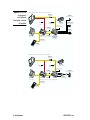

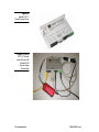

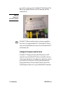
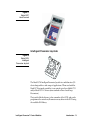
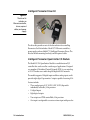
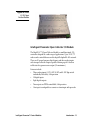
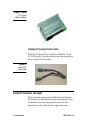

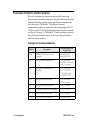

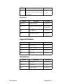

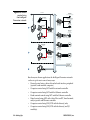
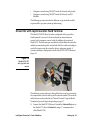
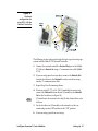
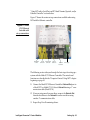

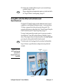
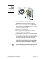

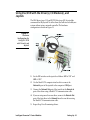


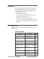

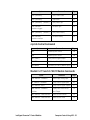
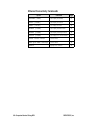
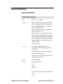


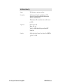
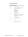

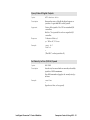

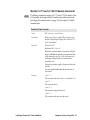


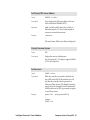
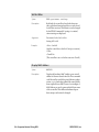
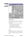


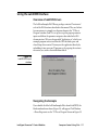
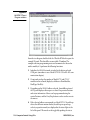


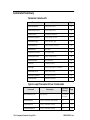

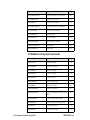


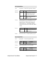
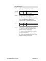
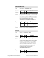
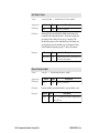


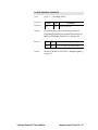
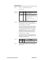
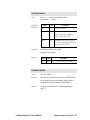
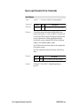


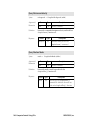
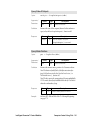

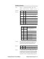
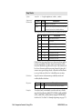
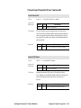
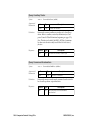


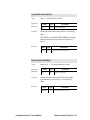

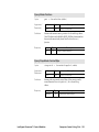
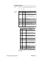
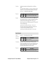

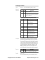
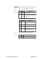
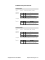
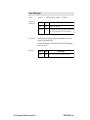
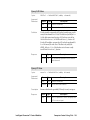

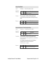

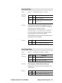
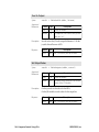

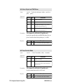
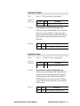
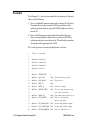
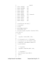


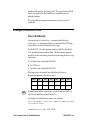
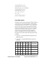
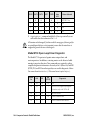
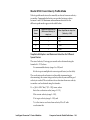
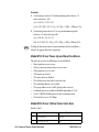

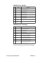


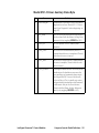
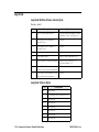


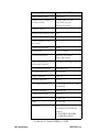
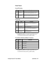
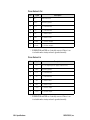


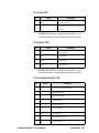
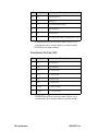
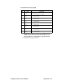


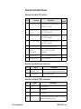

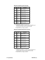

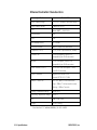
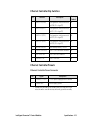
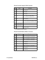


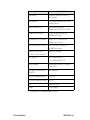
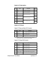
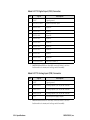

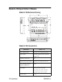

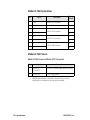
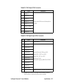
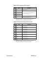

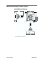
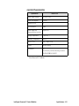
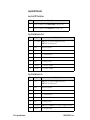
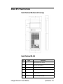

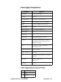

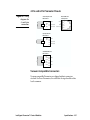
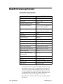
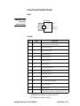


![Lite Reader Getting Started Guide [In Progress]](http://vs1.manualzilla.com/store/data/005692633_1-050fc996995aae18a2c8846f796d5b4a-150x150.png)