1
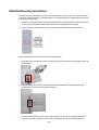
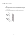
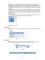
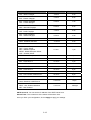
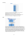
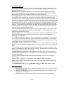
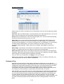
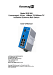
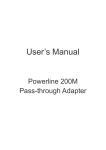
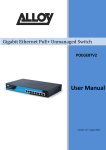
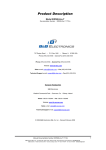
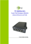
EIS-408FX-M & EIS-408FX-S 8-Port Managed Industrial Ethernet Switch (6x 10Base-T/100Base-TX and 2x 100Base-FX) User’s Manual ACROMAG INCORPORATED Tel: (248) 624-1541 30765 South Wixom Road Fax: (248) 624-9234 P.O. BOX 437 Wixom, MI 48393-7037 U.S.A. Copyright 2005, Acromag, Inc., Printed in the USA. Data and specifications are subject to change without notice. 8500-786-A05K000 Table of Contents Chapter 1 Introduction ........................................................................................................ 1-1 Overview..................................................................................................... 1-1 Ethernet Switching Technology .................................................................. 1-1 Key Product Features ................................................................................. 1-3 Package Contents ...................................................................................... 1-3 Chapter 2 Hardware Installation......................................................................................... 2-1 Introduction ................................................................................................. 2-1 Panel Layout .............................................................................................2-1 Reset Button .............................................................................................2-2 LED Indicators ..........................................................................................2-2 DIP Switches .............................................................................................2-3 Connecting Input Power ............................................................................. 2-3 Connecting to the Output Relay.................................................................. 2-3 Connecting to the Ethernet Ports................................................................ 2-3 Connecting to the Fiber Ports ..................................................................... 2-5 DIN-Rail Mounting Installation .................................................................... 2-6 Wall-Mounting Installation........................................................................... 2-7 Chapter 3 Web-based Management ................................................................................... 3-1 Introduction ................................................................................................. 3-1 Preparation for Web Management.............................................................. 3-1 System Login .............................................................................................. 3-1 Configuration via the Web-based Management Interface .......................... 3-2 Menu Bar Introduction ..............................................................................3-2 Configuring Your Switch............................................................................3-2 Chapter 4 Troubleshooting ................................................................................................. 4-1 Power Connections..................................................................................... 4-1 Incorrect Connections................................................................................. 4-1 Faulty or Loose Cables .............................................................................4-2 Non-Standard Cables ...............................................................................4-2 Improper Network Design .........................................................................4-2 LED Indicators ............................................................................................ 4-2 Appendix A Specifications.....................................................................................................A-1 Data and Specifications are subject to change without notice. Windows® is a registered trademark of Microsoft Corporation. 1 Chapter 1 Introduction Overview Ethernet Switching Technology Key Product Features Package Contents Installation Guide Overview The EIS-408FX-M and EIS-408FX-S are web-managed, industrial Ethernet rail switches that have six 10/100MBaseTX ports, plus two 100BaseFX ports (multi-mode “-M” or single-mode “-S” models), and are designed to operate under harsh environmental conditions. These switch models also include advanced support for media redundancy and offer communication fail-over times less than 300 milliseconds. These switch models also have a wide operating ambient range and include redundant power inputs with reverse polarity protection. The unit includes a DC-IN jack and may be optionally powered from an AC-DC wall transformer for Small Office/Home Office (SOHO) applications. It is packaged in a rugged, IP-30 aluminum enclosure for increased protection from extreme temperature, vibration, dust, and debris. This switch has also passed several safety certifications to help ensure safe and reliable data transmission for industrial applications. In addition to supporting the Spanning Tree Protocol (STP) and Rapid Spanning Tree Protocol (RSTP), this switch includes a proprietary redundant ring technology that allows it to manage a media loop with other switches of the same type. A media loop is created when a message sent out on one port is received by the same switch at another port (two message paths exist). This switch is smart enough to temporarily disable the second path, holding it as a backup in case the primary path fails. It also includes a normally closed alarm relay to signal a port failure (if enabled). The switch will automatically fail-over to a secondary path within 300ms if the primary path is lost. These switches also support SC-type fiber connections in both single-mode and multi-mode versions, useful for extending transmission distance. A web-based management interface ensures easy operation and reconfiguration via a standard internet web browser. Ethernet Switching Technology To better understand the operation of an Ethernet switch, we need to first differentiate it from a hub. An Ethernet hub (or repeater) is a device that is used to simply connect Ethernet nodes. Any message at one hub port is repeated on all ports. That is, hubs forward data packets they receive from a single station to all hub ports. As a result, all port devices connected to a single hub will share the same bandwidth. Then as nodes are added to the network hub, they compete for this finite amount of bandwidth and this can cause data collisions to occur, making network determinism impossible to attain, especially on busy networks. Now determinism is a term that is used to describe the ability to guaranty that a packet is sent or received in a finite and predictable amount of time. The inherent lack of determinism is the main reason that traditional Ethernet had problems being accepted for use in critical control applications, as most control systems have a defined time requirement for packet transmission, typically less than 100ms. 1-1 Switches on the other hand, are intelligent devices used to more efficiently connect distributed Ethernet nodes than a hub. Unlike a simple hub, a switch provides targeted data transfer, as it will forward a data packet to a specific port or network segment, rather than to all ports, thus freeing up bandwidth. The ability to target a packet to a specific port increases network throughput and helps to eliminate the collisions that have historically made Ethernet non-deterministic. So we see that by targeting the data transfer between ports, switches act as intelligent repeaters to increase network distances. In doing this, they actually split networks into separate collision domains at each port. Thus, switches increase determinism by reducing collisions. Switches also increase network bandwidth and throughput, as well as provide supplemental error checking on data packets to help ensure the integrity of forwarded data. Each port of this switch functions just like any other Ethernet device. It is able to receive and decode Ethernet frames, test for frame integrity, plus assemble and transmit Ethernet frames. With Ethernet, any device can try to send a data frame out at any time. If two devices happen to send a data frame at the same time, then a collision may occur. The arbitration protocol for carrier transmission access of the Ethernet network is called Carrier Sense Multiple Access with Collision Detect (CSMA/CD). With CSMA/CD, each device will first sense whether the line is idle and available for use. If it is, the device will begin to transmit its first frame. If another device also tries to send a frame at the same time, then a collision occurs and both frames are discarded. Each device then waits a random amount of time and retries its transmission until it is successfully sent. Unlike other Ethernet devices, such as an Ethernet host adapter or Network Interface Card (NIC), the port of a switch does not require its own MAC address. During retransmission of a received packet, the switch port will instead look like the originating device by having assumed its source address. This is why the Ethernet collision domain is said to terminate at the switch port. That is, a two-port switch will effectively break a network into two distinct data links or segments. An eight port switch like the Acromag EIS-408FX can break a network into 8 distinct data links or segments (also called collision domains). Since all Ethernet nodes are able to recognize the occurrence of a collision, and since the detection of a collision is principal to the way Ethernet arbitrates media access, large domains containing many nodes can become quite cumbersome. Thus, using an Ethernet switch to subdivide a large network into separate collision domains will certainly help to increase throughput. The current tendency in critical industrial control applications is to connect one Ethernet device per switch port. This will produce the most deterministic mode of operation as the switch can then operate full-duplex, with no chance of collisions. This ensures determinism, helping critical control applications to remain predictable and on-time. Each port of a switch forwards data to another port based on the MAC address contained in the received data packet/frame. In order to know which port to forward a data packet to, the switch will learn and store the MAC addresses of every device it is connected to, along with the associated port number. However, until the switch actually learns the port a particular address resides at (the first packet), it forwards this traffic to all ports just like a hub. The switch will its internal look-up table to quickly determine the location (port) of a node, establish a temporary connection between itself and the node, then terminate the connection once a packet is transferred. In this way, it increases network bandwidth and provides the network determinism required for critical control applications. This switch uses a store and forward algorithm to process Ethernet frames. That is, it first stores the Ethernet frame and examines it for errors before forwarding it to its destination. Although this method may seem to increase the forwarding time (latency) and possibly cause fragmentation, it effectively reduces the occurrence of error frames and improves overall throughput. This is particularly useful when there is heavy network traffic and or greater potential for noise and interference. 1-2 The industry-wide shift from Ethernet hubs to Ethernet switches has dramatically boosted the bandwidth of networks and helped to eliminate congestion problems inherent with the CSMA/CD protocol (Carrier Sense Multiple Access with Collision Detection). Since a switch operates by learning the location of addresses and forwarding messages directly, unnecessary traffic is greatly reduced. It will use auto-negotiation to regulate the speed and duplex of each port based on the capabilities of connected devices. These features combine with flow control allow a 100M node to effectively communicate with a 10M node without losing data. Connecting one device per switch port also allows two-way, simultaneous transmission to occur (full duplex), essentially doubling the bandwidth. Further, by segmenting a collision domain in this way, the need for non-deterministic carrier sensing (CSMA/CD) is eliminated. The utilization of a store-and-forward switching algorithm allows each packet to be inspected, and corrupt or redundant data to be filtered, further eliminating unnecessary traffic that often slows a network down. Key Product Features 8-port, 10Base-T/100Base-TX/FX managed industrial switch Supports IEEE 802.3 10Base-T, 802.3u 100Base-TX/100Base-FX Non-blocking, store-and-forward switching architecture 1Mbits embedded buffer memory with 2K entry MAC address table Web-based reconfiguration with easy-to-use GUI Redundant Media Ring support with 300ms fail-over Supports Spanning Tree Protocol (STP) and Rapid Spanning Tree Protocol (RSTP) Provides redundant dual DC power inputs with reverse polarity protection and alarm Provides an optional AC-DC wall transformer power input for SOHO applications Includes an alarm relay to signal port break and/or power failure RJ45 ports have automatic MDI/MDI-X crossover Supports IEEE 802.3x flow control for full-duplex operation Includes back pressure control for half-duplex operation Supports broadcast packet filtering Rugged aluminum case with IP30 rated protection Versatile DIN-rail, surface, and wall-mountable design Supports VLAN/QoS/IGMP Snooping Supports Class of Service (COS) Supports IGMP with query mode for multi media application Supports SNTP Supports port-based VLAN / 802.1Q Tag VLAN Package Contents One industrial web-managed Ethernet rail switch One DIN-Rail clip (attached to the switch) One wall mounting plate and six screws (separate accessory) Documentation and Software CD Quick Installation Guide If any of the above items are missing or damaged, please contact your local sales representative for replacement or repair. 1-3 2 Chapter 2 Hardware Installation This chapter includes the following installation and configuration information: Introduction ¾ Panel Layout ¾ Reset Button ¾ LED Indicators ¾ DIP Switches Connecting to Input Power Connecting to the Alarm Output Relay Connecting to the Ethernet Ports Connecting to the Fiber Ports DIN-Rail Mounting Installation Wall Mounting Installation Introduction Panel Layout Front View 1 LED indicators (PWR, RM, PWR1, PWR2, FAULT). 2 DIP switches (to enable port alarms and designate redundant Ring Master). 3 RJ-45 ports w/ integrated FDX/COL & LNK/ACT LED indication. 4 Fiber ports (SC type connector). 5. Reset Button Bottom View At the bottom of this switch is a ground screw and a 6-position plug-in terminal block connector with two DC power inputs and a relay connection. There is also a DC-IN power jack for connecting an optional AC-DC power adapter (wall transformer type). 2-1 Reset Button The reset button is located on the front panel just below the DIP switches and provides a quick and easy way to restart and restore switch settings to their default values. To simply restart the unit, press the reset button for 2 seconds and release. To restart and restore the switch to its factory default settings, press the button and hold for 5 seconds and release. Note that you must always restart a switch after setting its Ring Master DIP switch in order to activate the new DIP switch setting or the redundant ring will not operate. LED Indicators These switch models have 5 diagnostic LED’s and 16 Port LED’s located on the front panel. The following table describes the function of each LED indicator. Status LED PWR PWR 1 PWR 2 R.M FAULT Port LED LNK/ACT Fiber Ports 7 and 8 FDX/COL Fiber Ports 7 and 8 FDX/COL Port Status RJ45 Ports 1-6 LNK/ACT Status Description Green Any Power is ON (PWR1, PWR2, or DC-IN). OFF No power is being supplied. Green Power 1 is ON. OFF No power 1 is being supplied. Green Power 2 is ON. OFF No power 2 is being supplied. Green Indicates this switch is designated as the redundant Ring Master. OFF Indicates switch is NOT the Ring Master. Yellow Power, RJ45, or fiber port failure has occurred. OFF Normal operation (no power or port failure). Status Description Green A network device is detected. Blinks This port is transmitting to, or receiving packets from another transmitting device. OFF No device is attached. Yellow The port is operating in full-duplex mode. Blinks A collision of packets has occurred. OFF The port is in half-duplex mode or no device is attached. Yellow The port is operating in full-duplex mode. Blinking Yellow A collision of packets has occurred. OFF Port is in half-duplex mode or no device is attached. Green A network device is detected. Blinking Green Port is transmitting to, or receiving packets from another transmitting device. OFF No device is attached. 2-2 DIP Switches The DIP switches are used to set which switch in a redundant media ring is to be the Ring Master, and to separately enable the port alarms. DIP SWITCH R.M. P1 to P8 Status Description ON Set this switch to be the Ring Master. OFF Set this switch to NOT be the Ring Master. ON To enable the port break alarm at this port. OFF To disable the port break alarm at this port. Notes (DIP Switches): 1. If the corresponding port alarm DIP switch is set ON, when that port connection fails, the Fault LED will light up and the alarm relay contacts will close. 2. After you set a switch to be the Ring Master in a redundant media ring, you must restart this switch to activate the settings (see Reset Button) or ring redundancy will not operate. 3. Only one switch in a media ring should have its Ring Master switch set to ON. 4. In order for a redundant ring to operate, all switches in the ring must be of the same type (employ the same redundant ring method). Connecting Input Power IMPORTANT: It is good practice to turn off input and load power, and unplug the power terminal block before making wire connections. Otherwise, your screwdriver blade can inadvertently short your terminal connections to the grounded enclosure. 1. Insert the positive and negative wires of your DC supply into the V+ and V- contacts of the terminal block connector. The acceptable wire range is 12 to 24 AWG. 2. Tighten the terminal screws to prevent the wires from coming loose. 3. OPTIONAL – DC IN: This switch has an additional power jack for the connection of AC-DC power converters (wall-transformer type) designed for office use. Be sure that the output voltage is within the required 12-48V DC range and of sufficient capacity to power the unit. Refer to switch PWR LED to verify power via the DC-IN jack. Note: If all three power inputs are connected (DC IN, PWR 1, PWR 2), the switch will be powered from the highest connected voltage. The unit will not alarm for loss of DC IN power, the alarm function only applies to loss of power at PWR1 or PWR2. Connecting to the Output Relay The alarm output relay contacts are in located at the two middle terminals of the power terminal block, between PWR2 and PWR1 as shown in the figure below. These contacts are single-pole single-throw (SPST) and are energized (open-circuited) for normal operation. These contacts will close if the unit is not powered, or if either DC power 1 or power 2 fails, or if a port connection fails (if that port alarm DIP switch is ON). The figure below gives an example of how the output alarm relay operates. Note: The relay contacts are energized (open) for normal operation and will close for fault conditions. This contact does not supply any power and is rated up to 24V DC at 1A. 2-3 1. Connect to the SPST alarm relay terminals per your application. Insert your load wires and tighten the alarm terminal screws to prevent the wires from coming loose. These contacts are open for normal operation and close in alarm. Do not exceed 24V and 1A. 2. Verify that your load is wired to the center two terminals of this terminal block. After the power relay is wired, replace this terminal block into its socket. Connecting to the Ethernet Ports This switch includes six RJ-45 ports with automatic MDI/MDI-X crossover, and automatic 10/100Mbps data rate sensing for 10Base-T or 100Base-TX connections. Automatic MDI/MDI-X crossover allows you to connect to other switches, hubs, or workstations, without regard to using straight-through or crossover cabling. The following figures depict the schematic diagram of straight-through and crossover cabling. Note that crossover cables simply cross-connect the transmit lines at each end to the receive lines at the opposite end. Straight-through Cabling Schematic Crossover Cabling Schematic Note that Ethernet cables use pins 1, 2, 3, and 6 of an 8-pin RJ45 connector. The signals of these pins are converted by the automatic MDI-X function, as shown in the table below: 2-4 Pin MDI-X Signals MDI Signals 1 RD+ TD+ 2 RD- TD- 3 TD+ RD+ 6 TD- RD- Connect one side of an Ethernet cable into any switch port and connect the other side to your attached device. The green LNK LED will light up when the cable is correctly connected. Refer to the LED Indicators section for descriptions of each LED indicator. Always make sure that the cables between the switches and attached devices (e.g. switch, hub, or workstation) are less than 100 meters (328 feet). Two switches are now up-linked together. If we change the up-link port manually at this time, the MAC address table will change as well. After the MAC address table changes, then the data can be transmitted between these two switches. This period of time is called the MAC address table aging time. The switch’s default aging time is 5 minutes, which means that if you manually change the up-link port, you will need to wait up to 5 minutes before the data can be sent. If the aging time is too short, the MAC address table will constantly refresh, resulting in excess consumption of switch computing resources. For this reason, a longer aging time is recommended. Connecting to the Fiber Ports The automatic MDI/MDI-X crossover function does not apply to fiber connections, as these must be crossed over manually. To connect the fiber port on one switch to the fiber port of another switch, simply cross-connect the transmit channel at each end to the receive channel at the opposite end as illustrated in the figure below. These models have two 100Base-FX ports with SC type connectors (in multi-mode and single mode versions). Single-mode types have greater distance capability than multi-mode types, but single mode cable is generally more expensive. A fiber segment using single-mode cable must use 9/125 or 10/125 micrometer single-mode fiber cables. For single-mode, the connection distance can be up to 30 km. A fiber segment using multi-mode must use 50 or 62.5/125 micrometer multi-mode fiber cables. For multi-mode, the connection distance can be up to 2 km. 2-5 DIN-Rail Mounting Installation The DIN-Rail clip is attached to the rear of the switch via two screws. This clip may be removed for surface or wall mounting. If the DIN-Rail clip is not already attached, follow these instructions to attach the DIN-Rail clip. 1. Use the two screws provided to attach the DIN-Rail clip to the rear panel of the switch where shown below (note that the spring side of the DIN clip is positioned at the top). 2. For flat surface or wall mounting, you can remove the DIN-Rail clip in similar fashion. Follow these steps to mount the switch to the DIN-rail track. 1. Insert the upper end (spring side) of the DIN-rail clip onto the upper lip of the DIN-rail track as shown below. 2. Push the bottom of the switch inward by tilting it downward until it snaps onto the track. Check that the unit is firmly secured to the track. 3. To remove the Switch from the track, push downward on the unit to compress the spring, and pull the bottom outward from the track to disengage the unit and lift it off the track. 2-6 Wall-Mounting Installation Follow these steps to mount the unit to a wall or other flat surface. 1. Use a screwdriver to remove the two screws that secure the DIN-Rail clip to the back of the switch. 2. Use a screwdriver to attach the wall-mounting plate to the rear panel of the switch using the six screws provided. Tighten these screws to secure the switch to the wall-mounting plate. 3. Use the slotted holes at each corner of the wall-mounting plate to attach the unit to the wall or other flat surface. 4. To remove the unit from the wall and from the wall-mounting plate, reverse steps 1-3. 2-7 3 Chapter 3 Web-based Management This chapter includes the following information on how to configure and manage your switch via a web-based interface: Introduction Preparation for Web Management System Login Configuration via the Web-based Management Interface ¾ Menu Bar Introduction ¾ Configuring Your Switch Introduction Embedded HTML web pages are stored in non-volatile memory within the switch. These pages allow you to use a standard web-browser such as Microsoft Internet Explorer, or Mozila, to configure and interrogate the switch from anywhere on the network. The internal web-based management interface supports Internet Explorer 5.0 and Mozila 1.7.5 (including the FireFox version). These easy-to-use management screens are based on Java applets to minimize the consumption of network bandwidth and increase your access speed. Note: IE 5.0 or later versions do not allow Java applets to open sockets by default. Users have to directly modify the browser settings to selectively enable Java applets to use network ports. Preparation for Web Management Before you attempt to use the embedded web interface to manage switch operation, verify that the switch is properly installed on your network and that every PC on this network can access the switch via the web browser. 1. Verify that your network interface card (NIC) is operational, and that your operating system supports the TCP/IP protocol. 2. Wire DC power to the switch and connect your switch to your computer. 3. Make sure that the switch default IP address is 192.168.10.1. 4. Change your computer IP address to 192.168.10.2. 5. Switch to DOS command mode and ping 192.168.10.1 to verify a normal response time. System Login 1. Launch the Internet Explorer web browser on the PC. 2. Type http:// followed by the IP address of your switch. Then press Enter. 3. The switch login screen will appear next. 4. Key in the user name and password. The default user name and password is admin. 5. Click Enter or OK, and the home page of the management interface will appear. 6. Once you actually enter the management interface, you should change the switch IP address setting according to your network environment (consult your network administrator). 3-1 Configuration via the Web-based Management Interface Menu Bar Introduction Home Port Status Port Statistics IP Security Port Control IP SNTP RSTP Configuration Security Configuration TFTP Update Factory Manager Backup Firmware Default Switch Settings Redundant Ring Save Configuration Port Mirroring QoS VLAN Configuration IGMP System Reboot Rate Control Home - The home page of this embedded web-based management interface. Port Status - This section is to display the port status and applicable settings. Port Statistics - This section is to display the switch port data flow statistics. Port Control - This section is to configure the switch port settings. Switch Settings - This section is to display the information of the switch system. Port Mirroring - This section is to enable and configure port mirroring settings. VLAN Configuration - This section is to enable and configure VLAN settings. IP Configuration - This section is to set up the switch IP address. SNTP - This section is to enable the network time server (Simple Network Time Protocol). IP Security - This section configures the IP address for user access to the switch via the web. RSTP - This section is to enable and configure Rapid Spanning Tree Protocol (RSTP). Redundant Ring - This section is to enable and configure redundant ring settings. QoS - This section is to enable and configure QoS (Quality of Service) settings. IGMP - This section is to enable and configure the switch’s IGMP Snooping function. Security Manager - This section is used to change the username & password for access to this interface. Configuration Backup - This section is to backup the switch settings to a file on your PC. TFTP Update Firmware - This section is to use the TFTP utility to update the firmware of the switch (this is only done when instructed to do so by the factory). Factory Default - This section is to restore the factory default settings. Save Configuration - This section is used to save the switch settings to non-volatile memory. System Reboot - This section is used to reboot the switch. Rate Control – This section is used to setup each port’s bandwidth rate & packet limitation type. Configuring Your Switch Port Status This window allows you to view the status of each port as follows: Port: Indicates the port number. Type: Indicates the speed mode of the port (for example, 100TX means 100 Mbps). Link: “Down” indicates that a connection is not established; “Up” indicates a connection has been successfully established. State: Indicates whether the port is Enabled or Disabled. A disconnection is also denoted as “Disabled”. 3-2 Negotiation: “Auto” means that the switch will auto-negotiate the speed (automatically select 10M or 100M bps), and the transmission mode (full or half duplex), with the remote device. Force means that the switch will run according to your own forced settings for speed and duplex. Speed/Duplex: Configured and Actual - Refers to the port speed and duplex setting. The Config column shows the configuration set up by you, while the Actual column shows the actual speed of the port. Flow Control: Configured and Actual – “Symmetric” specifies that you need to activate the flow control function of the remote network device in order to let the flow control of that corresponding port of the switch to work. “Asymmetric” indicates that you don’t need to activate the flow control function of the remote network device. The flow control of that corresponding port on the switch will work anyway. Single Port Status To get the single port status screen, you can click directly on any port number displayed at left to see port-specific information for that port and similar to that listed below: Port Statistics In this section, you can view operation statistics for each port. Click Clear to reinitialize and clear any counts. Port Control Simply select the port you want to configure and you will be able to view the current status and settings of the selected port, and make changes to port settings as required. 3-3 In the State column, you can enable or disable control over this port. In Negotiation column, you can configure the auto-negotiation mode to Auto to enable automatic negotiation, or Force (to directly specify the speed/duplex on this port). In the Speed column, you can configure the speed of this port. In the Duplex column, you can configure the full-duplex or half-duplex mode of this port. In Flow Control column, “Symmetric” means that you need to activate the flow control function of the remote network device in order to allow the flow control mechanism of the corresponding port of the switch to work. “Asymmetric” means that you don’t need to activate the flow control function of the remote network device, as the flow control of the corresponding port of the switch will work anyway. Once you finish your configuration, click Apply to apply your settings. Note: Remember to click on the Save Configuration button to save your settings. Otherwise the settings you made will be lost when the switch is powered off. Switch Settings With the Switch Settings screen, you can assign a system name, location, and brief description. You can also view stored information. System Name: You can use this field to assign a name to the switch. System Location: You can use this field to specify the switch’s physical location. System Description: You can attach a brief description to the switch here. Firmware Version: Displays the firmware version installed in this switch. Kernel Version: Displays the kernel version in this switch. Hardware Version: Displays the hardware version of this switch. MAC Address: Displays the unique hardware address (MAC address) assigned by the manufacturer (the default setting). Once you finish your configuration, click Apply to apply your settings. Note: Always remember to select Save Configuration to save your settings. Otherwise, the settings you made will be lost when the switch is powered OFF. 3-4 Port Mirroring Port mirroring (also called port spanning) is a tool that allows you to mirror the traffic from one or more ports onto another port, without disrupting the flow of traffic on the original port. Any traffic that goes into or out of the monitored port(s) will be duplicated at the mirror port. This traffic can then be analyzed at the mirror port using a monitoring device. A network administrator will typically utilize this tool for diagnostics or debugging, or to fend off attacks. Port Mirroring State: Select the mirroring mode - Disable, Rx, Tx, or Both Rx & Tx. Analysis Port: This is the mirror port. You can analyze the traffic of all the monitored ports at this port without affecting the flow of traffic on the port(s) being monitored. A network administrator would typically connect a LAN analyzer or Netxray device to this port. Monitor Port(s): These are the ports you want to monitor. The traffic of all monitored ports will be copied to the mirror ports. You can choose a single port, or any combination of ports, but you can only monitor them in one mirror mode. To disable this function, set the monitor port to None. Once you finish your configuration, click on Apply to apply your settings. Note: Always remember to select Save Configuration to save your settings. Otherwise, the settings you made will be lost when the switch is powered off. VLAN Configuration A Virtual LAN (VLAN) is a “logical” grouping of nodes for the purpose of limiting a broadcast domain to specific members of a group, but without physically grouping the members together. That is, a VLAN allows you to isolate network traffic so that only members of the VLAN would receive traffic from the same VLAN members. Basically, creating a VLAN from a switch is the logical equivalent of physically reconnecting a group of network devices to another Layer 2 switch, without actually disconnecting these devices from their original switch. This switch supports both port-based and 802.1Q (tagged-based) VLAN’s. The VLAN Operation Mode is set to “disable” by default. 3-5 Port-based VLAN The packets that a switch receives and identifies as belonging to a port-based VLAN are forwarded only over the ports assigned to that VLAN. Ports not selected as belonging to a VLAN are treated as if they belong to another single VLAN. Port based VLAN’s are limited to the ports of a single switch and do not allow membership to cross boundaries into other switches, as with tag-based VLAN’s. Further, if a port-based VLAN is enabled, any VLAN-tagging will be ignored. 1. 2. 3. 4. 5. 6. 7. Click Add to add a new VLAN group. Enter a VLAN group name, group IP, and then select the members for this VLAN group. Click on Apply to adopt the settings. Next, you will see your VLAN group displayed. If the group list is longer than one page, you can click Next Page to view other VLAN groups. Use the Delete button to delete any unwanted VLAN’s. Use the Edit button to modify the existing VLAN’s. Note: Always remember to select Save Configuration to save your settings. Otherwise, the settings you made will be lost when the switch is powered off. Because the port-based VLAN is defined on the switch itself and does not use information contained in the packet frame to define its membership, it is restricted to ports of the same switch. Effectively, only the switch itself knows the architecture of a port-based VLAN, while the segments connected to the switch ports have no way of knowing the VLAN definition even exists. This is the key difference between port and tag based Virtual LAN’s. 802.1Q VLAN This tag-based VLAN is an IEEE 802.1Q standard, which allows VLAN’s to be created across different switches (see Figure 1). IEEE 802.1Q tag-based VLAN’s make use of VLAN control information stored in a VLAN header attached to IEEE 802.3 packet frames. This tag contains a VLAN Identifier (VID) that indicates which VLAN a frame belongs to. Since a switch only has to check a frame’s tag, without the need to dissect the contents of the frame, this also saves a lot of computing resources within the switch. Figure.1 Tagged VLAN 3-6 Basic 1. Click on Add button to add a new tag-based VLAN. 3-7 2. Group Name: You can name your new VLAN grouping here. The Group Name is simply a reference for the network administrator to help differentiate VLAN’s. 3. VLAN ID: Enter a VLAN ID here (12 bits). Enter any value from 2 to 4094 (default value is 1). The VLAN ID is used by the switches to identify the different VLAN’s and this is encoded into the IEEE 802.1q frame. 4. Select specific ports of this switch to be included in the VLAN from the available ports box. Click Add to add ports to the VLAN, or Remove to remove ports from the VLAN. Then click Next to continue. Please note that each VLAN will require a “tagged port”. Different VLAN’s use these tagged ports to communicate with one another. 5. Here you can specify the egress (outgoing) VLAN frames to be Tagged frames or Untagged frames. Click on Apply to apply your settings. Tag: Indicates that egress/outgoing frames are to be VLAN tagged. Untag: Indicates that egress/outgoing frames are not VLAN tagged. Port VID Port VLAN ID (PVID): Enter the port VLAN ID here. The Port VID (PVID) allows the switches to identify which port belongs to which VLAN. To keep things simple, it is recommended that you set the Port VID equivalent to the VLAN ID’s. You can skip tagged ports, as tagged ports do not need Port VLAN ID’s. To reset to default values, click Default. Once you finish your configuration, click Apply to apply your settings. Note: Always remember to select Save Configuration to save your settings. Otherwise, the settings you made will be lost when the switch is powered off. 3-8 How To Set Up a 802.1q VLAN – Reference Example. Group A Group B To illustrate a tag-based VLAN, we would like to use all Port 1’s and Port 2’s of switch 1 and switch 2 to form a VLAN Group A, and all Port 5’s and Port 6’s to form a VLAN Group B. This will restrict VLAN A and VLAN B from communicating with each other, except through their port 8’s which they will use to transmit data to each other (this is their tagged port). The tagged VLAN settings for switch 1 are as follows (settings for switch 2 are the same those for switch 1): 1. You must specify which port(s) belong to the VLAN. Click Add to create VLAN A. Enter a group name and a VLAN ID (VID) for VLAN A (you cannot use “1” as a VLAN ID, as “1” is reserved for the default VID). Use Add to include the ports that are to belong to this VLAN (Port 1 and Port 2). Don’t forget to include the tagged/uplink port (uplink Port 8). Repeat Step 1.1 to 1.3 to create VLAN B. 3-9 2. Be sure to setup the Tag (uplink) Port (port 8 for our example). Thus, VLAN A and VLAN B can only communicate with one another via transmission from their port 8. Use this software to specify the Tag port for both VLAN A and VLAN B. 3. Set the Port VLAN ID. Follow the instructions described in Port VLAN ID (PVID) section to set up the port VLAN ID’s for each Untag port. It is recommended that each port’s PVID be set to the same value as the VLAN ID (VID) to which it belongs. Tag (uplink) ports do not use port VLAN ID’s. 4. Always remember to select Save Configuration to preserve your settings. Otherwise, your settings will be lost when the switch power is turned OFF. 5. Repeat steps 1-4 to set up the second switch (the settings for the second switch are the same). 6. Since the settings for the second switch are exactly the same as the first one, you can use the Configuration Backup function to copy the first switch settings and restore them to the second switch. This will reduce the time required to setup the second switch. Refer to the Configuration Backup section for more information. 3-10 IP Configuration This function allows users to configure the switch’s IP address settings. DHCP Client: You can elect to Enable or Disable the DHCP Client function. When the DHCP Client function is enabled, an IP address will be assigned to the switch from the network’s DHCP server. In this mode, the default IP address will therefore be replaced by the one assigned by the DHCP server. If the DHCP Client is disabled, then the IP address that you specify will be used instead. IP Address: You can assign the IP address that your network has reserved for your switch. If the DHCP Client function is enabled, you do not need to define an IP address for the switch, as it will be overwritten by the DHCP server and shown here. The default IP is 192.168.10.1. Subnet Mask: You can assign the subnet mask for the IP address here. If the DHCP Client function is enabled, you don’t need to assign the subnet mask. Gateway: You can assign the gateway for the switch here. The default gateway is 192.168.10.254. Once you finish your configuration, click on Apply to apply your settings. SNTP The Simple Network Time Protocol (SNTP) is an adaptation of the Network Time Protocol (NTP), used to synchronize computer clocks on the internet. You can configure the SNTP settings here for the purpose of synchronizing the clocks of several switches on the network. SNTP is maintained by the Internet Engineering Task Force (IETF). SNTP Client: Select Enable to acquire the current time from the SNTP server, or Disable to disable this feature. Daylight Saving Time: You can activate the Daylight Savings Time function here. UTC Time-zone: Select the time zone where the switch is located. The following reference table lists time zones for different locations: 3-11 Local Time Zone Conversion from UTC Time at 12:00 UTC ADT - Atlantic Daylight -3 hours 9 am AST - Atlantic Standard EDT - Eastern Daylight -4 hours 8 am EST - Eastern Standard CDT - Central Daylight -5 hours 7 am CST - Central Standard MDT - Mountain Daylight -6 hours 6 am MST - Mountain Standard PDT - Pacific Daylight -7 hours 5 am PST - Pacific Standard ADT - Alaskan Daylight -8 hours 4 am ALA - Alaskan Standard -9 hours 3 am HAW - Hawaiian Standard -10 hours 2 am Nome, Alaska -11 hours 1 am CET - Central European FWT - French Winter MET - Middle European MEWT - Middle European Winter SWT - Swedish Winter +1 hour 1 pm EET - Eastern European, USSR Zone 1 +2 hours 2 pm BT - Baghdad, USSR Zone 2 +3 hours 3 pm ZP4 - USSR Zone 3 +4 hours 4 pm Local Time Zone Conversion from UTC Time at 12:00 UTC ZP5 - USSR Zone 4 +5 hours 5 pm ZP6 - USSR Zone 5 +6 hours 6 pm WAST - West Australian Standard +7 hours 7 pm CCT - China Coast, USSR Zone 7 +8 hours 8 pm JST - Japan Standard, USSR Zone 8 +9 hours 9 pm EAST - East Australian Standard GST Guam Standard, USSR Zone 9 +10 hours 10 pm IDLE - International Date Line NZST - New Zealand Standard NZT - New Zealand +12 hours Midnight SNTP Server IP: You can set the IP address of the SNTP server here. Switch Timer: The current time of the switch will be shown here. Once you finish your configuration, click on Apply to apply your settings. 3-12 IP Security In this section, you can set up to four specific IP addresses to grant authorization for management access to this switch via a web browser. Enable IP Security: Check this option to enable the IP security function. Security IP1 to IP4: You can assign up to four specific IP addresses and only these IP addresses will be granted access to manage this switch via the web browser. Once you finish your configuration, click on Apply to apply your settings. RSTP If a switch has more than one path to a destination, this leads to message loops that can generate broadcast storms and quickly bog down a network. The spanning tree was created to combat the negative effects of message loops in switched networks. A spanning tree uses a spanning tree algorithm (STA) to automatically sense that a switch has more than one way to communicate with a node. Then it selects the best path (primary), and blocks the other path(s). It also keeps track of the blocked path(s) in case the primary path fails. The Spanning Tree Protocol (STP) introduced a standard method for accomplishing this and this is specified in IEEE 802.1d. Later, the Rapid Spanning Tree Protocol (RSTP) was adopted and represents the evolution of STP, providing much faster spanning tree convergence after a topology change. This switch supports both RSTP and STP (all switches that support RSTP are also backward compatible with switches that support only STP). 3-13 System Configuration Under the “System Configuration” tab, you can change the spanning tree settings and view the Root Bridge Information. Note that switches are also referred to as bridges. Root bridges are related to the spanning tree. RSTP Mode: You must first enable the STP or RSTP mode, before configuring any related parameters. The parameter settings required for both STP and RSTP are the same. Note that 802.1d refers to STP mode, while 802.1w refers to the faster RSTP mode. Priority (0-61440): This value must be in multiples of 4096 and represents the bridge ID number. This number is used to identify the root bridge. A root bridge continuously transmits network topology information to other bridges (switches) using the spanning tree protocol and serves to notify other bridges on the network when topology changes are required. It is located where the paths that frames take through the network are assigned, and usually centrally located to provide the shortest path to other links on the network. Like a hub, a root bridge will forward frames out to all of its ports. Every network should have one root bridge and it is usually assigned the lowest bridge ID. The bridge with the lowest bridge ID number has the highest priority, and is selected as the root bridge. If you happen to change this value, you must reboot the switch to cause the system to assign a new path priority number. Note that you increase this switches priority by selecting a lower number. A device with a lower number has a higher bridge priority and thus a greater chance of being established as the root bridge of the spanning tree topology. Max Age (6-40): Enter a value from 6 to 40 seconds here. This value represents the time that a bridge will wait without receiving Spanning Tree Protocol configuration messages before attempting a reconfiguration. If this switch is not the root bridge, and it has not received a hello message from the root bridge in an amount of time equal to Max Age, then this switch will reconfigure itself as a root bridge. Then once two or more devices on the network are recognized as a root bridge, the devices will renegotiate to set up a new spanning tree topology. Hello Time (1-10): Enter a value from 1 to 10 seconds here. This is the periodic timer that drives the switch to send out the BPDU (Bridge Protocol Data Unit) packet to check on the current STP status. The root bridge of the spanning tree topology periodically sends out a “hello” message to other devices on the network to check if the topology is “healthy”. The “hello time” is the amount of time the root waits between sending hello messages. Forward Delay Time (4-30): Enter a value between 4 and 30 seconds. This value is the time that a port waits before changing from the Spanning Tree Protocol learning and listening states to the forwarding state. The is the amount of time this switch will wait before checking to see if it should change to a different state. Once you have completed your configuration, click on Apply to apply your settings. Note: You must observe the following rule to configure the Hello Time, Forwarding Delay, and Max Age parameters. 2 × (Forward Delay Time – 1 sec) □ Max Age Time □ 2 × (Hello Time value + 1 sec) Suggested Strategy: 1. Select a Hello Time value and compute the rightmost portion of the rule above to get the lower limit of Max Age. 2. Select a Forward Delay time and compute the leftmost portion of the rule above to get the upper limit of Max Age. 3. Select a Max Age from 6 to 40 seconds that is between the limits computed above. 3-14 Per Port Configuration Select the port you wish to configure and you will be able to view the current settings and status of the port. Path Cost: Enter a number between 1 and 200,000,000. This value represents the “cost” of the path to the other bridge from this transmitting bridge at the specified port. Priority: Enter a value between 0 and 240, using multiples of 16. This is the value that decides which port should be blocked by priority in a LAN. Admin P2P: Some of the rapid state transitions that are possible within RSTP depend upon whether the port of concern can only be connected to one other bridge (i.e. it is served by a point-to-point LAN segment), or if it can be connected to two or more bridges (i.e. it is served by a shared-medium LAN segment). This function allows the P2P status of the link to be manipulated administratively. “True” means P2P is enabled, while “False” means P2P is disabled. Admin Edge: A port directly connected to the end stations cannot create a bridging loop in the network. To configure this port as an edge port, set the port to the True state. Admin Non STP: Status shown here indicates whether this port includes the STP mathematic calculation. True means that this port does NOT include the STP mathematic calculation. False means that this port includes the STP mathematic calculation. Once you finish your configuration, click Apply to save your settings. Note: Always remember to select Save Configuration to save your settings. Otherwise, your new settings will be lost when the switch is powered off. Redundant Ring Redundant ring technology provides a faster redundant media fail-over recovery than the Spanning Tree Protocol (STP), or Rapid Spanning Tree Protocol (RSTP). But unlike STP/RSTP, it additionally requires that all switches in the media ring be of the same brand (have the same redundant ring method), as most redundant ring algorithms are proprietary and rarely interoperable. Since STP and RSTP are standard IEEE protocols, switches that employ these two methods of media redundancy are generally interoperable with one another. With redundant ring, every switch in the ring must support the same redundant ring method and have two ring member ports. One switch in this ring is dedicated to serve as Ring Master, and one of its two member ports will be temporarily blocked--this is referred to as the backup port. The other member port is called the working port. The other switches in the ring are called working switches, and both their member ports are called working ports. When a segment of this ring fails, the backup port/path will automatically become a working port/path to recover the failure. 3-15 The “RM” DIP switch of this model is used to configure the switch as Ring Master (ON), or slave (OFF). Only one switch may assume the role of Ring Master. The Ring Master has the right to negotiate and send commands to other switches in the ring group. When the switch is configured to be the redundant Ring Master, the ring configuration interface will display a message indicating that this switch is the Ring Master. The system also supports a coupled ring function which allows two or more redundant ring groups to be connected together to provide a redundant backup solution. Enable Super Ring: You can enable the redundant ring function by checking this option. Note: You must enable the redundant ring function before connecting any backup path to prevent the inadvertent generation of message loops. Working Ports: You can assign 2 ports as member ports here. One port will be the working port, the other will be the backup port (the Ring Master will automatically decide which port functions as the working port, and which one is the backup port). Once you finish your configuration, click on Apply to apply your settings. Do not complete the ring until you have already setup all the ring switches, or message loops may develop immediately. IMPORTANT: If you enable the redundant ring function (Super Ring), you must disable RSTP. The redundant ring function and the RSTP function cannot both be enabled at the same time. How to Set Up a Redundant Ring? 3-17 Here we use four switches to form a redundant ring topology. Switch 1 is configured to be the Ring Master. One of its ports will be a working port, and the other port will be blocked and connects to the backup/redundant path (the upper right corner path is the backup path). The settings of Switch 1. The settings of Switch 2. The settings of Switch 3. The settings of Switch 4. Note: Before you connect a backup path to complete the loop, you need to finish configuring all the ring switches as described above. Otherwise, it will cause an immediate message loop problem. 3-18 Can 3 Switches Form a Super Ring Topology? Here we use three switches to build a simple media ring. Each ring switch is connected such that it has two message paths to another. Switch 1 is configured to be the master switch, and the backup path will be decided by this master switch. For our example, we specified the path on the right as the backup path. The Master switch blocks the member port connected to this backup path. The settings of Switch 1. The settings of Switch 2. 3-19 The settings of Switch 3. Note: Before you connect the backup path (last loop segment), you need to complete the settings described above for all of the ring switches. Otherwise, you could create an immediate message loop problem. QoS QoS (Quality of Service) is a broad term that refers to measures taken to specify a guaranteed throughput level. QoS with respect to this switch utilizes the prioritization of traffic to accomplish this. This section allows you to configure the QoS settings for each port with regard to setting priorities. QoS Policy You can select a QoS policy rule as follows: Use an 8, 4, 2, 1 weighted fair-queuing scheme. The switch will follow 8:4:2:1 rate to process packets in a queue from the highest priority to the lowest priority. For example, the system will process 8 packets with the highest priority in the queue, then 4 with middle priority, then 2 with low priority, and 1 with the lowest priority, at the same time. Use a strict priority scheme: Packets with a higher priority in the queue will always be processed first, except when there is no packet with a higher priority. Priority Type Each port has five priority types that you may select. Port-based: The port priority will follow the default port priority that you have assigned – high, middle, low, or lowest. COS only: The port priority will only follow the COS priority that you have assigned. TOS only: The port priority will only follow the TOS priority that you have assigned. COS first: The port priority will follow the COS priority first, and then the other priority rule. TOS first: The port priority will follow the TOS priority first, and then the other priority rule. 3-20 Default Priority Type This is to decide the default priority of each port. COS Priority: This is to map the COS priority (level 0~7) to port priority (4 levels). TOS Priority: This is to map the TOS priority (level 0~63) to port priority (4 levels). IGMP The IGMP (Internet Group Management Protocol) is an Internet Protocol that provides a way for an internet device to report its multicast group membership to adjacent routers. Multicasting allows one computer on the internet to send data to a multitude of other computers that have identified themselves as being interested in receiving the originating computers data. Multicasting is useful for such applications as updating the address books of mobile computer users in the field, sending out newsletters to a distribution list, and broadcasting streaming media to an audience that has tuned into the event by setting up multicast group membership. In effect, IGMP manages multicast traffic by making use of switches, routers, and hosts that support IGMP. Enabling IGMP allows the ports to detect IGMP queries, report packets, and manage multicast traffic through the switch. IGMP has three fundamental types of messages, as shown below: 3-21 Message Description Query A message sent from the querier (an IGMP router or switch) which asks for a response from each host that belongs to the multicast group. Report A message sent by a host to the querier to indicate that the host wants to be, or is already a member of a given group indicated in the report message. Leave Group A message sent by a host to the querier to indicate that the host has quit as a member of a specific multicast group. You can enable the IGMP protocol and IGMP Query functions here. You will see the information of the IGMP Snooping function in this section, including different multicast groups’ VID and member ports, and IP multicast addresses that range from 224.0.0.0 to 239.255.255.255. Once you finish your configuration, click on Apply to apply your settings. Security Manager You can change the user name and the password here for increased security. User name: You can key in a new user name here. The default setting is “root”. Password: You can key in the new password here. The default setting is “root”. Confirm Password: You need to type in the new password again to confirm it (yes, I know this is annoying). Once you finish your configuration, click Apply to apply your settings. Configuration Backup In the Configuration Backup section, you can restore a backup configuration to the switch. You also can backup a configuration to the TFTP server as well. TFTP Restore Configuration 3-22 You can restore EEPROM values directly from the TFTP server. But before you can do that, you must have already placed the backup image on the TFTP server, which allows you to download this image back to flash memory in the switch. TFTP Server IP Address: Enter the IP address of your TFTP server here. Restore File Name: Enter the correct restore file name here. Once you finish your configuration, click on Apply to apply your settings. TFTP Backup Configuration You can save the current flash ROM value from the switch to the TFTP server. This will allow you to later go to the TFTP Restore Configuration page to restore this image value back to the switch. TFTP Server IP Address: Enter the IP address of your TFTP server here. Backup File Name: Specify the correct backup file name here. Once you finish your configuration, click on Apply to apply your settings. TFTP Update Firmware In this section, you can update to the latest firmware for your switch. Before you do so, make sure that you have your TFTP server ready, and the firmware image for this switch is already installed on the TFTP server. IMPORTANT: You do not normally need to update your firmware, except for special circumstances or when instructed to do so by the factory. TFTP Server IP Address: Type in the IP address of your TFTP server here. Firmware File Name: Type in the file name of the firmware image. Once you finish your configuration, click on Apply to apply your settings. Note: Always remember to click on the Save Configuration button to save your settings. Otherwise, the settings you made will be lost when the switch is powered off. 3-23 Factory Default In this section, you can reset the switch to its default settings as shown below: Default IP address: 192.168.10.1 Default Gateway: 192.168.10.254 Subnet Mask: 255.255.255.0 Other switch settings will be set to “disable” or “none”. Click on Default to reset your switch to its default settings as shown above. Note: This provides a quick method for clearing the switch’s internal settings. However, it will not restore the IP address to the default setting. If you want to restore all the settings to their default state, including the IP address, please use the reset button on the front panel of your switch (refer to the Reset Button section). System Reboot System Reboot allows you to reset the switch software. Click Reboot to reboot your switch software. Note: Always remember to click on the Save Configuration button to save your settings. Otherwise, the settings you made will be lost when the switch is powered off. Save Configuration Save Configuration allows you to save your configuration to non-volatile flash memory. Powering the switch OFF without clicking Save Configuration will cause any new settings to be lost. After selecting Save Configuration, click on the Save Flash button to save your new configuration. 3-24 Rate Control Rate limiting is a form of flow control that is used to enforce a strict bandwidth limit at a port. You can program separate transmit (egress) and receive (ingress) rate limits at each port, and even apply the limit to certain packet types as described below. Limit packet type: You can select the packet type that you want to be filtered. The packet types listed here include broadcast/multicast/unknown unicast packets, broadcast/multicast packets, and broadcast only packets. The broadcast/multicast/unknown unicast packet, broadcast/multicast packet, and broadcast packet only are only for ingress packets (incoming packets). The egress (outgoing) rate only supports “All” packet types. Bandwidth: Ports 1-8 support port ingress (incoming traffic) and egress (outgoing traffic) rate controls. For example, let’s assume port 1 is at 10Mbps--you can set its effective transmit/egress rate to be 1Mbps, and receive/ingress rate to be 500 Kbps. The switch then uses the packet counter to control the number of packets coming in so that the configured ingress rate can be achieved. Ingress: Select the ports effective ingress rate here. Valid values are 1Mbps, 2Mbps, 4Mbps, 8Mbps, 16Mbps, 32Mbps and 64Mbps. The default value is “disable”. Egress: Select the ports effective egress rate here. Valid values are 128kbps, 256Kbps, 512Kbps, 1Mbps, 2Mbps, 4Mbps, and 8Mbps. The default value is “disable”. Click on Apply to apply your settings. Note: Always remember to click on the Save Configuration button to save your settings. Otherwise, the settings you made will be lost when the switch is powered off. IMPORTANT: Both QoS and Rate Control settings cannot exist at the same time. 3-25 4 Chapter 4 Troubleshooting This chapter includes some information for general troubleshooting as follows: Power Connections Incorrect Connections ¾ Faulty or Loosen Cables ¾ Non-standard Cables ¾ Improper Network Technologies LED Indicators Power Connections This unit is powered from 12-48V DC. You should verify that the output of your DC supply voltage, or AC-DC power adapter, remains within the required 12 to 48V DC range while under load (it should be capable of supplying at least 6W of power for this model). IMPORTANT: Never exceed 48V DC or you will damage the switch. If you are using an AC-DC power adapter and the DC-IN power indicator (PWR) of the switch does not light when the power cord is plugged in, you may have a faulty power cord. Check for loose or broken power connections. Also check for power loss or power surges at the AC power outlet. Verify that your AC-DC adapter is properly sized and outputs the correct voltage under load. Incorrect Connections Select Ethernet cables with specifications suitable for your application. In general, Ethernet cables are categorized into unshielded twisted-pair (UTP) and shielded twisted-pair (STP) types. Shielded cables are recommended. In general, category 3, 4, and 5 Ethernet cables are suitable for systems with 10Mbps transmission speed. But for systems at 100Mbps, you should only use Category 5 or better Ethernet cables. Gigabit ports should use Cat-5 or Cat-5e cables for 1000Mbps connections. In addition, always make sure that the cable length between device ports does not exceed 100 meters (328 feet). The RJ45 ports of this switch automatically detect straight-through or crossover cables and then cross-connect the transmit and receive channels when you connect the switch to another device. This feature does not apply to the fiber port connections. You must manually cross-connect transmit and receive cables between the fiber ports of connected devices. For fiber connections, make sure that the fiber cable type matches the fiber model (multi-mode or single-mode). For the RJ-45 connectors, use the correct UTP or STP cables as required. For 10/100M ports, use 2 pairs of twisted cables. For Gigabit 1000T ports, use 4 pairs of twisted cables. If the RJ-45 connectors and cables are not correctly connected, the link will fail and the green LNK LED will not light. 4-1 Faulty or Loose Cables Visually inspect for loose or faulty connections at all connectors and cables. If that does not correct the problem, try replacing the cable. Non-standard Cables Non-standard and incorrectly-wired cables may generate increased network collisions or other network problems which will impair network performance. A common Category 5 cable tester is a great tool for troubleshooting network installations and is highly recommended. Improper Network Design Verify that your network has been properly designed. Most errors simply result from poor quality cable, poor cable routing, network congestion, improper cable length, and too many repeater/hubs between end nodes. Errors may also result from inadvertent data path loops (redundant message paths). Message loops can generate broadcast storms that can bog down a network. There should be only one active message path between any two nodes on a network. Excessive collisions may be indicative of a cable that is too long. It may also signal the presence of too many repeaters (hubs) between devices and can also be indicative of a congested network (too many nodes in one segment). A high number of undersized an fragmented packets can result from interference induced into the network cable, by either passing it too close to noisy devices, or because of problems with the network devices themselves. In these instances, check for improper cabling, damaged cables, or cables routed too closely to noisy equipment or other wiring. A high number of oversized packets can result from a bad transceiver, excessive cable noise, or from a speed mismatch between the switch ports and the connected devices. LED Indicators The switch can also be visually monitored via its own front-panel LED indicators. This can be useful to assist in identifying common problems and to help you find possible solutions. Check the redundant PWR1 and PWR2 LED’s to verify DC power. The PWR LED will light for any connected power (PWR1, PWR2, or DC-IN). Check PWR for power via an AC adapter connected to DC-IN. If the power LED indicator does not light when the power cord is plugged in, you might have a problem with the power outlet, or the power cord. If the switch simply powers OFF on its own after running for a period of time, check for loose power connections, power losses, or surges at the power outlet. You should also verify that your supply voltage remains within the required 12-48VDC range while under load. Refer to the port Link LED (LNK) to verify that a connection has been properly established (solid green). A blinking green LNK LED indicates communication activity. If the LNK LED remains off after making a connection, then no device has been detected and the cable may be bad or the connected device may be un-powered. Refer to the Collision LED (COL) to monitor for excessive collisions. A blinking COL LED indicates that collisions have occurred. This LED will be solid ON for a full duplex connection, as collisions cannot occur for full-duplex. A full-duplex connection can be achieved by simply connecting one device per switch port, and this is the most deterministic mode of operation. 4-2 A Appendix A Specifications Protocols IEEE 802.3 10Base-T Ethernet IEEE 802.3u 100Base-TX Fast Ethernet IEEE 802.3x Flow Control and back pressure IEEE 802.1p class of service IEEE 802.1Q VLAN CSMA/CD (Carrier Sense Multiple Access w/Collision Detection) Technology Non-blocking, store-and-forward switching architecture Transmission Rate 14880pps for 10Base-T, 148800pps for 100Base-TX/FX MAC Address Table Size 2K MAC address table Transfer packet size 64 bytes to 1522 bytes (with VLAN tag) Memory Buffer 1024K bits Per port: Link/Activity (Green) Full Duplex/Collision (Orange/Yellow) Per unit: Power 1, Power 2 , Power (Green) Fault (Orange), Ring Master (Green) 10BaseT: Twisted-pair UTP/STP Cat 3, 4, or 5 cable EIA/TIA-568 100-ohm (100m maximum length) 100BaseT(X): Twisted-pair UTP/STP Cat 5 cable EIA/TIA-568 100-ohm (100 meters maximum length) 100BaseFX: Select multi-mode or single-mode cables per model. Standards LED’s Network Cables Power Input 12 to 48 VDC, redundant dual DC power inputs with reverse polarity protection and a removable terminal block for master and slave VDC power inputs. Power Consumption 6 watts Back-plane 1.6Gbps Relay alarm current/voltage Up to 1A and 24V DC Installation DIN-Rail kit (attached) and wall-mounting panel (accessory included) Operating Temperature -10ºC to 70 ºC (14 ºF to 158ºF) Operating Humidity 5 to 95% (non-condensing) Storage Temperature -40ºC to 85ºC Dimensions 54 mm (W) x 135 mm (H) x 105 mm (D) EMI FCC Class A EMC EN61000-4-2, EN61000-4-3, EN61000-4-4, EN61000-4-5, EN6100-4-6, EN61000-4-8, EN61000-4-11 Safety UL, cUL, CE/EN60950 (consult factory for others). Stability IEC60068-2-32 (free fall test), IEC60068-2-27 (shock test), IEC60068-2-6 (vibration test). A-1