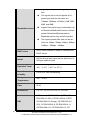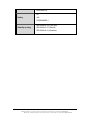
1
Product Description Model EIR508-2xx-T Documentation Number: 707 Dayton Road EIR508-2xx-T 1713m -- P.O. Box 1040 -- Ottawa, IL 61350 USA Phone (815) 433-5100 -- General Fax (815) 433-5105 Phone (815) 433-5100 -- General Fax (815) 433-5105 Website: www.bb-elec.com Sales e-mail: [email protected] -- Fax (815) 433-5109 Technical Support e-mail: [email protected] -- Fax (815) 433-5104 European Headquarters B&B Electronics Westlink Commercial Park -- Oranmore, Co. Galway, Ireland Phone +353 91-792444 -- Fax +353 91-792445 Website: www.bb-europe.com Sales e-mail: [email protected] Technical Support e-mail: [email protected] © 2008 B&B Electronics Mfg. Co. Inc. - Revised February 2008 Manual Documentation Number: EIR508-2xx-T 1713m B&B Electronics Mfg Co Inc – 707 Dayton Rd - PO Box 1040 - Ottawa IL 61350 - Ph 815-433-5100 - Fax 815-433-5104 – www.bb-elec.com B&B Electronics – Westlink Commercial Park – Oranmore, Galway, Ireland – Ph +353 91-792444 – Fax +353 91-792445 – www.bb-europe.com 1 Eight Port Managed Industrial Ethernet Switches User Manual 2 Manual Documentation Number: EIR508-2xx-T 1713m B&B Electronics Mfg Co Inc – 707 Dayton Rd - PO Box 1040 - Ottawa IL 61350 - Ph 815-433-5100 - Fax 815-433-5104 – www.bb-elec.com B&B Electronics – Westlink Commercial Park – Oranmore, Galway, Ireland – Ph +353 91-792444 – Fax +353 91-792445 – www.bb-europe.com FCC This Equipment has been tested and found to comply with the limits for a Class-A digital device, pursuant to Part 15 of the FCC rules. These limits are designed to provide reasonable protection against harmful interference. This equipment generates uses and can radiate radio frequency energy and, if not installed and used in accordance with the instructions, may cause harmful interference to radio communications. However, there is no guarantee that interference will not occur in a particular installation. If this equipment does cause harmful interference to radio or television reception, which can be determined by turning the equipment off and on, the user is encouraged to try to correct the interference by one or more of the following measures: Reorient or relocate the receiving antenna. Increase the separation between the equipment and receiver. Connect the equipment into an outlet on a circuit different from that to which the receiver is connected. Consult the dealer or an experienced radio/TV technician for help. CE This is a Class-A product. In a domestic environment this product may cause radio interference in which case the user may be required to take adequate measures. Manual Documentation Number: EIR508-2xx-T 1713m B&B Electronics Mfg Co Inc – 707 Dayton Rd - PO Box 1040 - Ottawa IL 61350 - Ph 815-433-5100 - Fax 815-433-5104 – www.bb-elec.com B&B Electronics – Westlink Commercial Park – Oranmore, Galway, Ireland – Ph +353 91-792444 – Fax +353 91-792445 – www.bb-europe.com 3 Content Introduction ................................................................ 8 Features ................................................................... 8 Package Contents .................................................... 9 Hardware Description .............................................. 10 Physical Dimension (W x H x D) ............................ 10 Front Panel ............................................................. 10 Reset Button ................................................................... 10 Bottom View ........................................................... 11 DIP-switch .............................................................. 12 LED Indicators ........................................................ 14 Ports ....................................................................... 15 Cabling ................................................................... 17 Wiring the Power Inputs ......................................... 17 Wiring the Fault Alarm Contact .............................. 18 Mounting Installation ............................................... 19 DIN-Rail Mounting .................................................. 19 Panel Mounting ...................................................... 21 Hardware Installation............................................... 22 4 Manual Documentation Number: EIR508-2xx-T 1713m B&B Electronics Mfg Co Inc – 707 Dayton Rd - PO Box 1040 - Ottawa IL 61350 - Ph 815-433-5100 - Fax 815-433-5104 – www.bb-elec.com B&B Electronics – Westlink Commercial Park – Oranmore, Galway, Ireland – Ph +353 91-792444 – Fax +353 91-792445 – www.bb-europe.com Installation Steps .................................................... 22 Network Application ................................................ 23 X-Ring Application .................................................. 23 Coupling Ring Application ...................................... 24 Dual Homing Application ........................................ 25 Web-Based Management ........................................ 26 About Web-based Management ............................ 26 Preparing for Web Management ............................ 26 System Login.......................................................... 26 Port status .............................................................. 28 Single Port Information .................................................... 28 Port Statistics ......................................................... 29 Port Control ............................................................ 30 Switch Setting......................................................... 31 Port Mirroring.......................................................... 32 VLAN configuration ................................................ 33 Port-based VLAN ............................................................ 33 802.1Q VLAN .................................................................. 36 Alert ........................................................................ 39 Manual Documentation Number: EIR508-2xx-T 1713m B&B Electronics Mfg Co Inc – 707 Dayton Rd - PO Box 1040 - Ottawa IL 61350 - Ph 815-433-5100 - Fax 815-433-5104 – www.bb-elec.com B&B Electronics – Westlink Commercial Park – Oranmore, Galway, Ireland – Ph +353 91-792444 – Fax +353 91-792445 – www.bb-europe.com 5 Email Alert Configuration ................................................. 39 Event Configuration ......................................................... 41 Power Alarm Configuration .............................................. 42 IP Configuration...................................................... 43 SNTP Configuration ............................................... 44 IP Security .............................................................. 47 RSTP Configuration ............................................... 48 System Configuration ...................................................... 48 Per Port Configuration ..................................................... 49 X-Ring .................................................................... 51 QoS Configuration .................................................. 52 IGMP ...................................................................... 55 Security Manager ................................................... 56 SNMP Configuration............................................... 56 System Options ............................................................... 57 Community strings ........................................................... 57 Trap Manager .................................................................. 58 Configuration Backup ............................................. 58 TFTP Restore Configuration ............................................ 58 TFTP Backup Configuration ............................................ 59 TFTP Update Firmware .......................................... 59 6 Manual Documentation Number: EIR508-2xx-T 1713m B&B Electronics Mfg Co Inc – 707 Dayton Rd - PO Box 1040 - Ottawa IL 61350 - Ph 815-433-5100 - Fax 815-433-5104 – www.bb-elec.com B&B Electronics – Westlink Commercial Park – Oranmore, Galway, Ireland – Ph +353 91-792444 – Fax +353 91-792445 – www.bb-europe.com Factory Default ....................................................... 60 System Reboot ....................................................... 60 Save Configuration ................................................. 61 Rate Control ........................................................... 61 System Log ............................................................ 62 System Log ..................................................................... 62 Event Configuration ......................................................... 63 Trouble shooting...................................................... 65 Technical Specifications ......................................... 66 Manual Documentation Number: EIR508-2xx-T 1713m B&B Electronics Mfg Co Inc – 707 Dayton Rd - PO Box 1040 - Ottawa IL 61350 - Ph 815-433-5100 - Fax 815-433-5104 – www.bb-elec.com B&B Electronics – Westlink Commercial Park – Oranmore, Galway, Ireland – Ph +353 91-792444 – Fax +353 91-792445 – www.bb-europe.com 7 Introduction The Elinx EIR508 series of Industrial Managed Ethernet Switches provide powerful functionality in a small package. Designed for industrial applications, these switches are highly reliable Features Conforms to IEEE 802.3 10Base-T, 802.3u 100Base-TX/100Base-FX 6 10/100TX and 2 100FX ports (fiber models only) 8 10/100TX ports (all copper model) Auto MDI/MDI-X Store-and-Forward switching architecture Wide-range redundant power inputs DIN rail and panel mount design 2K MAC address table Web management GUI 4 priority queues per port IEEE 802.3x flow control Flow control with full-duplex Back pressure with half-duplex Class of service IGMP with Query mode for multi media application Ingress packet filter and egress rate limit. SNTP/SMTP Port mirror for TX or TX and RX packet. Alarm Relay Output X-Ring Redundant Ring Technology Reverse Polarity Protection on power inputs 1M bits Embedded memory Port based VLAN / 802.1 Q Tag VLAN IEEE 802.1p class of service and provide port base, Tag base and Type of service priority method 8 Manual Documentation Number: EIR508-2xx-T 1713m B&B Electronics Mfg Co Inc – 707 Dayton Rd - PO Box 1040 - Ottawa IL 61350 - Ph 815-433-5100 - Fax 815-433-5104 – www.bb-elec.com B&B Electronics – Westlink Commercial Park – Oranmore, Galway, Ireland – Ph +353 91-792444 – Fax +353 91-792445 – www.bb-europe.com DHCP client SNMP, Web Management, RMON TFTP firmware update, system configuration, restore, and backup. Package Contents One Industrial Ethernet Switch One Quick Start Guide One CD ROM containing users manual One DIN-Rail Clip (attached to the switch) One panel mount plate and six screws If any item is damaged or missing, contact B&B Electronics. Manual Documentation Number: EIR508-2xx-T 1713m B&B Electronics Mfg Co Inc – 707 Dayton Rd - PO Box 1040 - Ottawa IL 61350 - Ph 815-433-5100 - Fax 815-433-5104 – www.bb-elec.com B&B Electronics – Westlink Commercial Park – Oranmore, Galway, Ireland – Ph +353 91-792444 – Fax +353 91-792445 – www.bb-europe.com 9 Hardware Description Physical Dimension (W x H x D) 2.3 x 5.7 x 4.3 in (5.8 x 14.5 x 10.9 cm) Front Panel Front Panel of the industrial switch Reset Button The reset button is used to restart the reboot the switch or restore it to the factory default configuration. Restart: Press the button for 2 seconds and release. Set to factory default value: Press the button for 5 seconds and release. 10 Manual Documentation Number: EIR508-2xx-T 1713m B&B Electronics Mfg Co Inc – 707 Dayton Rd - PO Box 1040 - Ottawa IL 61350 - Ph 815-433-5100 - Fax 815-433-5104 – www.bb-elec.com B&B Electronics – Westlink Commercial Park – Oranmore, Galway, Ireland – Ph +353 91-792444 – Fax +353 91-792445 – www.bb-europe.com Bottom View The bottom panel of the industrial switch has one terminal block connector within two DC power inputs and fault relay contacts. Bottom Panel of the industrial switch Manual Documentation Number: EIR508-2xx-T 1713m B&B Electronics Mfg Co Inc – 707 Dayton Rd - PO Box 1040 - Ottawa IL 61350 - Ph 815-433-5100 - Fax 815-433-5104 – www.bb-elec.com B&B Electronics – Westlink Commercial Park – Oranmore, Galway, Ireland – Ph +353 91-792444 – Fax +353 91-792445 – www.bb-europe.com 11 DIP-switch The nine position DIP-switch is used to configure the relay alarm ring master mode. The default value for each position is OFF. Software configuration is also required for the alarm relay. The alarm relay contacts are normally open. DIP Switch No Status Description OFF Disable port 1 Alarm ON Enable port 1 Alarm. OFF Disable port 2 Alarm ON Enable port 2 Alarm. OFF Disable port 3 Alarm ON Enable port 3 Alarm. OFF Disable port 4 Alarm ON Enable port 4 Alarm. OFF Disable port 5 Alarm ON Enable port 5 Alarm. OFF Disable port 6 Alarm 1 2 3 4 5 6 12 Manual Documentation Number: EIR508-2xx-T 1713m B&B Electronics Mfg Co Inc – 707 Dayton Rd - PO Box 1040 - Ottawa IL 61350 - Ph 815-433-5100 - Fax 815-433-5104 – www.bb-elec.com B&B Electronics – Westlink Commercial Park – Oranmore, Galway, Ireland – Ph +353 91-792444 – Fax +353 91-792445 – www.bb-europe.com ON Enable port 6 Alarm. OFF Disable port 7 Alarm ON Enable port 7 Alarm. OFF Disable port 8 Alarm ON Enable port 8 Alarm. OFF Disable the ring master function 7 8 9 ON Enable the switch as the ring master in the X-Ring group [NOTE] Restart the switch after the X-Ring DIP switch is set. [NOTE] The Alarm Relay Output requires software configuration in addition to the DIP Switch setting. Manual Documentation Number: EIR508-2xx-T 1713m B&B Electronics Mfg Co Inc – 707 Dayton Rd - PO Box 1040 - Ottawa IL 61350 - Ph 815-433-5100 - Fax 815-433-5104 – www.bb-elec.com B&B Electronics – Westlink Commercial Park – Oranmore, Galway, Ireland – Ph +353 91-792444 – Fax +353 91-792445 – www.bb-europe.com 13 LED Indicators There are 7 diagnostic LEDs located on the front panel. They provide real time status information. LED Status Green Power Off Meaning The switch is on The switch is off or no power input is available. Green Power source 1 is available. Off Power source 1 is not available. Green Power source 2 is available. Off Power source 2 is not available. Power 1 Power 2 Yellow Fault Off Green Power failure or port failure (See Alarm setting for operational details) Normal Operation The switch is the master of an X-Ring group R.M. (Ring Master) Off The switch is not the master of an X-Ring group Green The port is linked Blinks The port is transmitting or receiving Off No device attached LNK/ACT (Port 7 & 8) Yellow FDX/COL (Port 7 & 8) Blinks Off 14 The port is operating in full-duplex mode Data Packet Collision The port in half-duplex mode or is not connected to a device Manual Documentation Number: EIR508-2xx-T 1713m B&B Electronics Mfg Co Inc – 707 Dayton Rd - PO Box 1040 - Ottawa IL 61350 - Ph 815-433-5100 - Fax 815-433-5104 – www.bb-elec.com B&B Electronics – Westlink Commercial Park – Oranmore, Galway, Ireland – Ph +353 91-792444 – Fax +353 91-792445 – www.bb-europe.com Ports RJ-45 ports There are 5 (or 8) 10/100Mbps auto-sensing ports for 10Base-T or 100Base-TX device connection. The ports are auto-sensing and auto MDI/MDIX. RJ-45 Pin Assignments Pin Number Assignment 1 Tx+ 2 Tx- 3 Rx+ 6 Rx- All copper ports on this switch support automatic MDI/MDI-X operation. Straight-through cables can be used for all network connections. In straight-through cable, pins 1, 2, 3, and 6, at one end of the cable, are connected straight through to pins 1, 2, 3 and 6 at the other end of the cable. The table below shows the 10BASE-T/100BASE-TX MDI and MDI-X port pin outs. Pin MDI-X Signal Name MDI Signal Name 1 Receive Data plus (RD+) Transmit Data plus (TD+) 2 Receive Data minus (RD-) Transmit Data minus (TD-) 3 Transmit Data plus (TD+) Receive Data plus (RD+) 6 Transmit Data minus (TD-) Receive Data minus (RD-) Manual Documentation Number: EIR508-2xx-T 1713m B&B Electronics Mfg Co Inc – 707 Dayton Rd - PO Box 1040 - Ottawa IL 61350 - Ph 815-433-5100 - Fax 815-433-5104 – www.bb-elec.com B&B Electronics – Westlink Commercial Park – Oranmore, Galway, Ireland – Ph +353 91-792444 – Fax +353 91-792445 – www.bb-europe.com 15 Straight Through Cable Schematic Cross Over Cable Schematic Fiber Port (Fiber Models Only) There are two 100Base-FX ports. Depending on the model, the fiber ports have either SC or ST type connectors and use multi-mode (2Km) or single mode (30Km) cable. Connect the fiber ports as described below. ATTENTION This is a Class 1 Laser/LED product. Do not stare into the Laser/LED Beam. 16 Manual Documentation Number: EIR508-2xx-T 1713m B&B Electronics Mfg Co Inc – 707 Dayton Rd - PO Box 1040 - Ottawa IL 61350 - Ph 815-433-5100 - Fax 815-433-5104 – www.bb-elec.com B&B Electronics – Westlink Commercial Park – Oranmore, Galway, Ireland – Ph +353 91-792444 – Fax +353 91-792445 – www.bb-europe.com Cabling Use Category 5 cabling for RJ-45 port connections. The cable must be less than 328 ft (100 meters) long. Use 9/125 um cable for single-mode fiber. Distances up to 30 Kilometers are supported. Use 50/125 or 62.5/125 cable for multi-mode fiber. Distances up to 2Km are supported. Wiring the Power Inputs V- V+ V- V+ 1. Insert the positive and negative wires into the V+ and Vconnector on the terminal block connector. 2. Tighten the wire-clamp screws. [NOTE] Use 12~ 24 AWG wire. Manual Documentation Number: EIR508-2xx-T 1713m B&B Electronics Mfg Co Inc – 707 Dayton Rd - PO Box 1040 - Ottawa IL 61350 - Ph 815-433-5100 - Fax 815-433-5104 – www.bb-elec.com B&B Electronics – Westlink Commercial Park – Oranmore, Galway, Ireland – Ph +353 91-792444 – Fax +353 91-792445 – www.bb-europe.com 17 Wiring the Fault Alarm Contact The fault alarm contact is located in the middle of terminal block connector as shown below. Insert the wires and set the Dipswitch to “ON”. When a power source fails or a link fault occurs the relay contacts will close. 1A@24V Insert the wires into the fault alarm contact [NOTE] Use12~ 24 AWG wire. [NOTE] Relay contacts are normally open. [NOTE] The Relay Alarm also requires software configuration. Refer to the Web Based Management Alert Section. 18 Manual Documentation Number: EIR508-2xx-T 1713m B&B Electronics Mfg Co Inc – 707 Dayton Rd - PO Box 1040 - Ottawa IL 61350 - Ph 815-433-5100 - Fax 815-433-5104 – www.bb-elec.com B&B Electronics – Westlink Commercial Park – Oranmore, Galway, Ireland – Ph +353 91-792444 – Fax +353 91-792445 – www.bb-europe.com Mounting Installation DIN-Rail Mounting Rear Panel of the switch DIN-Rail 1. Use the screws to screw the DIN-Rail to the industrial switch 2. To remove the DIN-Rail, reverse the step 1. Manual Documentation Number: EIR508-2xx-T 1713m B&B Electronics Mfg Co Inc – 707 Dayton Rd - PO Box 1040 - Ottawa IL 61350 - Ph 815-433-5100 - Fax 815-433-5104 – www.bb-elec.com B&B Electronics – Westlink Commercial Park – Oranmore, Galway, Ireland – Ph +353 91-792444 – Fax +353 91-792445 – www.bb-europe.com 19 20 1. First, insert the top of DIN-Rail into the track. 2. Then, lightly push the DIN-Rail into the track. 3. Ensure the DIN-Rail is tightly secured on the track. 4. To remove the industrial switch from the track, reverse steps above. Manual Documentation Number: EIR508-2xx-T 1713m B&B Electronics Mfg Co Inc – 707 Dayton Rd - PO Box 1040 - Ottawa IL 61350 - Ph 815-433-5100 - Fax 815-433-5104 – www.bb-elec.com B&B Electronics – Westlink Commercial Park – Oranmore, Galway, Ireland – Ph +353 91-792444 – Fax +353 91-792445 – www.bb-europe.com Panel Mounting 1. Remove the DIN-Rail. 2. Place the panel mount plate on the rear panel of the industrial switch. 3. Attach the plate with the screws provided. 4. Use the hook holes at the corners of the plate to mount the switch to the panel. 5. To remove the panel mount plate, reverse steps above. Manual Documentation Number: EIR508-2xx-T 1713m B&B Electronics Mfg Co Inc – 707 Dayton Rd - PO Box 1040 - Ottawa IL 61350 - Ph 815-433-5100 - Fax 815-433-5104 – www.bb-elec.com B&B Electronics – Westlink Commercial Park – Oranmore, Galway, Ireland – Ph +353 91-792444 – Fax +353 91-792445 – www.bb-europe.com 21 Hardware Installation Installation Steps 1. Unpack the switch 2. Ensure the DIN-Rail is tightly screwed to the switch. If it is not, refer to DIN-Rail Mounting section. If panel mounting is desired, refer to Panel Mounting Section. 3. Mount the switch. 4. Apply power to the switch. The power LED will light up. 5. Connect CAT 5 cables to the industrial switch’s RJ-45 ports and the network devices. [NOTE] If the network devices do not support MDI/MDI-X, a crossover cable will be required. 6. (Fiber Models Only) Connect the fiber optic cables to the industrial switch and the network devices. Ensure that the switch’s fiber optic transmitter is connected to the network devices receiver and vice versa. 7. When all the connections are made and the LED’s show normal indication, the installation is complete. 22 Manual Documentation Number: EIR508-2xx-T 1713m B&B Electronics Mfg Co Inc – 707 Dayton Rd - PO Box 1040 - Ottawa IL 61350 - Ph 815-433-5100 - Fax 815-433-5104 – www.bb-elec.com B&B Electronics – Westlink Commercial Park – Oranmore, Galway, Ireland – Ph +353 91-792444 – Fax +353 91-792445 – www.bb-europe.com Network Application X-Ring Application The EIR508 series of Industrial Switches incorporate the X-Ring Protocol to ensure network reliability and system restoration within 300 ms in the event of a connection failure. The X-Ring algorithm is similar to the spanning tree protocol (STP) algorithm but it has faster recovery time. The following figure below is an example of an X-Ring application. Manual Documentation Number: EIR508-2xx-T 1713m B&B Electronics Mfg Co Inc – 707 Dayton Rd - PO Box 1040 - Ottawa IL 61350 - Ph 815-433-5100 - Fax 815-433-5104 – www.bb-elec.com B&B Electronics – Westlink Commercial Park – Oranmore, Galway, Ireland – Ph +353 91-792444 – Fax +353 91-792445 – www.bb-europe.com 23 Coupling Ring Application If the network has more than one X-Ring group, the coupling ring function is used to connect them and add redundancy. This ensures that transmissions between the two ring groups will not fail. The figure below is an example of the coupling ring application. 24 Manual Documentation Number: EIR508-2xx-T 1713m B&B Electronics Mfg Co Inc – 707 Dayton Rd - PO Box 1040 - Ottawa IL 61350 - Ph 815-433-5100 - Fax 815-433-5104 – www.bb-elec.com B&B Electronics – Westlink Commercial Park – Oranmore, Galway, Ireland – Ph +353 91-792444 – Fax +353 91-792445 – www.bb-europe.com Dual Homing Application The Dual Homing function is used to prevent a connection loss between the X-Ring group and the upper level/core switch. Assign a port in each X-ring group to be the Dual Homing ports The Dual Homing function can only be used when the X-Ring function is active. Each X-Ring group can have one Dual Homing port. [NOTE] In the Dual Homing architecture, the upper level switches must have Rapid Spanning Tree protocol enabled. Manual Documentation Number: EIR508-2xx-T 1713m B&B Electronics Mfg Co Inc – 707 Dayton Rd - PO Box 1040 - Ottawa IL 61350 - Ph 815-433-5100 - Fax 815-433-5104 – www.bb-elec.com B&B Electronics – Westlink Commercial Park – Oranmore, Galway, Ireland – Ph +353 91-792444 – Fax +353 91-792445 – www.bb-europe.com 25 Web-Based Management About Web-based Management The switch has an embedded HTML web site residing in flash memory. This site offers advanced management features and allows the switch to be configured from anywhere on the network. The web site is designed for Internet Explorer 6.0 and uses Java Applets to reduce bandwidth consumption, enhance access speed, and present an intuitive user interface. Preparing for Web Management Before using web management, install the industrial switch on the network and verify that a PC on the local network can connect with the switch through the web browser. The default IP Address, Subnet Mask, Username and Password is listed below: IP Address: 192.168.16.1 Subnet Mask: 255.255.255.0 Default Gateway: 192.168.16.254 User Name: root Password: root System Login 26 Manual Documentation Number: EIR508-2xx-T 1713m B&B Electronics Mfg Co Inc – 707 Dayton Rd - PO Box 1040 - Ottawa IL 61350 - Ph 815-433-5100 - Fax 815-433-5104 – www.bb-elec.com B&B Electronics – Westlink Commercial Park – Oranmore, Galway, Ireland – Ph +353 91-792444 – Fax +353 91-792445 – www.bb-europe.com 1. Launch Internet Explorer on the PC. 2. Enter “http:// “+” the IP address of the switch”, in the address window and then Press “Enter”. 3. The login screen will appear. 4. Enter the user name and password. Press “Enter” or ”OK”, the home screen will appear. Function Menu Bar Home Interface Panel Figure Display Configuration Display Screen Manual Documentation Number: EIR508-2xx-T 1713m B&B Electronics Mfg Co Inc – 707 Dayton Rd - PO Box 1040 - Ottawa IL 61350 - Ph 815-433-5100 - Fax 815-433-5104 – www.bb-elec.com B&B Electronics – Westlink Commercial Park – Oranmore, Galway, Ireland – Ph +353 91-792444 – Fax +353 91-792445 – www.bb-europe.com 27 Port status Shows the status of each port Port: Displays the port number Type: Displays the speed and mode, ex: 100TX = 100Mbps Link: Displays the ports status (up or down) State: Displays the ports status (disabled or enabled). Unlinked is displayed as “off ” Negotiation: Displays the auto negotiation mode (auto or forced). Speed Duplex: Displays the port connection speed. “Config” is the configured value. “Actual” is the current value. Flow Control: Displays the flow control status as “Symmetric” or “Asymmetric” in full mode. “Disable” means that flow control is not enabled “Config” indicates that the value is user configured. “Actual” is the current value of the port. Port Status interface Single Port Information 28 Manual Documentation Number: EIR508-2xx-T 1713m B&B Electronics Mfg Co Inc – 707 Dayton Rd - PO Box 1040 - Ottawa IL 61350 - Ph 815-433-5100 - Fax 815-433-5104 – www.bb-elec.com B&B Electronics – Westlink Commercial Park – Oranmore, Galway, Ireland – Ph +353 91-792444 – Fax +353 91-792445 – www.bb-europe.com Click the desired port on the Panel figure. The single port information window will display the current port information. Port information interface Port Statistics Displays port statistics. Manual Documentation Number: EIR508-2xx-T 1713m B&B Electronics Mfg Co Inc – 707 Dayton Rd - PO Box 1040 - Ottawa IL 61350 - Ph 815-433-5100 - Fax 815-433-5104 – www.bb-elec.com B&B Electronics – Westlink Commercial Park – Oranmore, Galway, Ireland – Ph +353 91-792444 – Fax +353 91-792445 – www.bb-europe.com 29 Click Clear button to reset. Port Statistics Interface Port Control Use to set up the port. 1. Select the port by scrolling down the Port column. The current port information will be displayed in the table below. 2. State: Enables or disables the port. 3. Negotiation: Sets the negotiation mode to Auto, Nway (specify the speed/duplex of the port and enable auto-negotiation), or Forced. 4. Speed: Sets the transmit speed of the port 5. Duplex: Sets the port to full-duplex or half-duplex Flow control: Sets flow control function to Symmetric or Asymmetric in Full Duplex mode (The default value is Disable) 6. Click Apply button to apply configuration 7. Select the port again to verity the configuration. 30 Manual Documentation Number: EIR508-2xx-T 1713m B&B Electronics Mfg Co Inc – 707 Dayton Rd - PO Box 1040 - Ottawa IL 61350 - Ph 815-433-5100 - Fax 815-433-5104 – www.bb-elec.com B&B Electronics – Westlink Commercial Park – Oranmore, Galway, Ireland – Ph +353 91-792444 – Fax +353 91-792445 – www.bb-europe.com Port Control interface Switch Setting Used to assign the system name, location and to view system information System Name: Assigns a name to the switch. The maximum length is 64 bytes System Location: Assigns a physical location for the switch. The maximum length is 64 bytes System Description: Displays the description of switch. This is read only and cannot be modified Firmware Version: Displays the firmware version Kernel Version: Displays the kernel software version Hardware version: Display the hardware version MAC Address: Display the unique hardware address assigned by manufacturer (this value is different for each switch) Manual Documentation Number: EIR508-2xx-T 1713m B&B Electronics Mfg Co Inc – 707 Dayton Rd - PO Box 1040 - Ottawa IL 61350 - Ph 815-433-5100 - Fax 815-433-5104 – www.bb-elec.com B&B Electronics – Westlink Commercial Park – Oranmore, Galway, Ireland – Ph +353 91-792444 – Fax +353 91-792445 – www.bb-europe.com 31 Port Mirroring Port mirroring is a method to monitor traffic in switched networks. This is accomplished by mirroring the traffic going in and out of the monitored ports to a specifically designated port (the mirror port). 1. Port Mirroring Mode: Sets the mirror mode. Select disable to disable port mirroring. Select TX to monitor data being transmitted by a port. Select both to monitor port data being transmitted and received by a port. The default value is “Disable”. 2. Analysis Port: This is the port used to see all monitored port traffic (This port can be connected to a LAN analyzer or Netxray). 3. Monitor Port: Check the box to monitor the port. Up to 4 ports can be designated as monitor ports. 4. Click Apply Prot Mirroring interface [NOTE] If the configuration is not saved, it will be lost when the switch is powered off. 32 Manual Documentation Number: EIR508-2xx-T 1713m B&B Electronics Mfg Co Inc – 707 Dayton Rd - PO Box 1040 - Ottawa IL 61350 - Ph 815-433-5100 - Fax 815-433-5104 – www.bb-elec.com B&B Electronics – Westlink Commercial Park – Oranmore, Galway, Ireland – Ph +353 91-792444 – Fax +353 91-792445 – www.bb-europe.com VLAN configuration A Virtual LAN (VLAN) can be thought of as a broadcast domain that exists within a switch or a defined set of switches. By grouping switch ports into VLANs, traffic flooding is limited since devices can only communicate directly with devices belonging to the VLAN. Creating a VLAN from a switch is the logical equivalent of reconnecting a group of devices to another Layer 2 switch. However, the network devices retain their same physical connection. The EIR508 series switches support port-based and 802.1Q (tagged-based) VLAN. In the default configuration, the VLAN option is disabled. VLAN Configuration interface Port-based VLAN With port-based VLAN, the port is assigned to a VLAN. Therefore, all devices attached to a given port should be members of the same VLAN. As with other VLAN configurations, the packets forwarded using this method do not leak into other VLAN domains on the network. After the port has been assigned to a VLAN, devices on the port cannot send to or receive from devices in other VLANs without the intervention of another layer 3 device or the ability to tag the data packet with a specific PVID. Manual Documentation Number: EIR508-2xx-T 1713m B&B Electronics Mfg Co Inc – 707 Dayton Rd - PO Box 1040 - Ottawa IL 61350 - Ph 815-433-5100 - Fax 815-433-5104 – www.bb-elec.com B&B Electronics – Westlink Commercial Park – Oranmore, Galway, Ireland – Ph +353 91-792444 – Fax +353 91-792445 – www.bb-europe.com 33 VLAN – PortBase interface 1. Click Add to add a new VLAN group. The EIR508 series supports up to 64 VLAN 34 2. Enter Group name, VLAN ID and select the members of VLAN group 3. Click Apply Manual Documentation Number: EIR508-2xx-T 1713m B&B Electronics Mfg Co Inc – 707 Dayton Rd - PO Box 1040 - Ottawa IL 61350 - Ph 815-433-5100 - Fax 815-433-5104 – www.bb-elec.com B&B Electronics – Westlink Commercial Park – Oranmore, Galway, Ireland – Ph +353 91-792444 – Fax +353 91-792445 – www.bb-europe.com VLAN—PortBase Add interface 4. The VLAN group will be displayed after it is clicked 5. Click 6. Use the Delete 7. Use to modify existing VLANs Next Page Edit to view the next VLAN Group button to delete unwanted VLANs [NOTE] If the configuration is not saved, it will be lost when the switch is powered off Manual Documentation Number: EIR508-2xx-T 1713m B&B Electronics Mfg Co Inc – 707 Dayton Rd - PO Box 1040 - Ottawa IL 61350 - Ph 815-433-5100 - Fax 815-433-5104 – www.bb-elec.com B&B Electronics – Westlink Commercial Park – Oranmore, Galway, Ireland – Ph +353 91-792444 – Fax +353 91-792445 – www.bb-europe.com 35 802.1Q VLAN Tagged-based VLAN is an IEEE 802.1Q specification which allows VLANs to be created across devices from different venders. IEEE 802.1Q VLAN uses a technique to insert a “tag” into the Ethernet frame. The tag contains a VLAN Identifier (VID). When the 802.1Q VLAN is enabled, all ports on the switch belong to a default VLAN (VID 1). The default VLAN can’t be deled. The EIR508 series will support up to 64 VLAN groups. 802.1q VLAN interface Basic 1. Click Add 2. Management VLAN ID: Used for Remote Management Security. When this option is selected, remote management is only available to the members of the indicated VLAN Group. Enter the specific VALN ID 36 Manual Documentation Number: EIR508-2xx-T 1713m B&B Electronics Mfg Co Inc – 707 Dayton Rd - PO Box 1040 - Ottawa IL 61350 - Ph 815-433-5100 - Fax 815-433-5104 – www.bb-elec.com B&B Electronics – Westlink Commercial Park – Oranmore, Galway, Ireland – Ph +353 91-792444 – Fax +353 91-792445 – www.bb-europe.com number in Management VLAN ID column, check the box, and click the apply button. Example: If the management VLAN ID is 101 and the VLAN Group ID 101 includes ports 1, 2, and 4, only ports 1, 2, and 4 can perform remote management functions on the switch. If a port is in multiple VLAN groups, it can still perform management functions as long as one VLAN group ID is equal to the Management VLAN ID. 3. Group Name: Assign a name for the new VLAN 4. VLAN ID: Enter a VLAN ID (2~4094). The default is 1 5. From the available ports box, select ports to add to the VLAN Group and click the Add button 802.1q VLAN –Add interface 6. Click Next to bring up the configuration interface. Manual Documentation Number: EIR508-2xx-T 1713m B&B Electronics Mfg Co Inc – 707 Dayton Rd - PO Box 1040 - Ottawa IL 61350 - Ph 815-433-5100 - Fax 815-433-5104 – www.bb-elec.com B&B Electronics – Westlink Commercial Park – Oranmore, Galway, Ireland – Ph +353 91-792444 – Fax +353 91-792445 – www.bb-europe.com 37 7. Select outgoing frames as VLAN tagged or untagged and then click Apply Port VID: Configure port VID settings 1. Port VLAN ID: Enter the port VLAN ID 2. Click Apply 3. To reset back to default value, click 38 Default button Manual Documentation Number: EIR508-2xx-T 1713m B&B Electronics Mfg Co Inc – 707 Dayton Rd - PO Box 1040 - Ottawa IL 61350 - Ph 815-433-5100 - Fax 815-433-5104 – www.bb-elec.com B&B Electronics – Westlink Commercial Park – Oranmore, Galway, Ireland – Ph +353 91-792444 – Fax +353 91-792445 – www.bb-europe.com 802.1q VLAN – Port VLAN ID interface [NOTE] If the configuration is not saved, it will be lost if the switch is powered off. Alert Email Alert Configuration When a specified event occurs, the switch will send an alert email. Email Alert: Enables or disable the function SMTP Server IP Address: Enter the mail server IP address Authentication: Mark the check box to enable and configure the email account and password for authentication Manual Documentation Number: EIR508-2xx-T 1713m B&B Electronics Mfg Co Inc – 707 Dayton Rd - PO Box 1040 - Ottawa IL 61350 - Ph 815-433-5100 - Fax 815-433-5104 – www.bb-elec.com B&B Electronics – Westlink Commercial Park – Oranmore, Galway, Ireland – Ph +353 91-792444 – Fax +353 91-792445 – www.bb-europe.com 39 Mail Account: Enter the email address used to send the alert. Ex: [email protected]. This account must exist on the mail server. Password: The email account password Confirm Password: Confirm the password E-mail Address of Recipient 1 ~ 4: Enter up to 4 e-mail accounts to receive the alert Click Apply Email Alert Configuration interface 40 Manual Documentation Number: EIR508-2xx-T 1713m B&B Electronics Mfg Co Inc – 707 Dayton Rd - PO Box 1040 - Ottawa IL 61350 - Ph 815-433-5100 - Fax 815-433-5104 – www.bb-elec.com B&B Electronics – Westlink Commercial Park – Oranmore, Galway, Ireland – Ph +353 91-792444 – Fax +353 91-792445 – www.bb-europe.com Event Configuration System event selection: 4 selections – Device cold start, Power status, SNMP Authentication Failure, and X-Ring topology changes. Mark the checkbox to select the event. When the selected events occur, the system will send out an email alert. Device cold start: Sends an alert when the device executes a cold start. Power status: Sends an alert when the power status changes. (i.e. power source 1 removed). SMNP Authentication Failure: Sends and alert when an SNMP authentication failure occurs. X-Ring topology change: Sends an alert when X-Ring topology has changes. Port event selection: An e-mail alert can be sent for port specific events. Three selections are available: Link UP, Link Down, and Link UP & Link Down. Link UP: Sends an alert when the link comes up. Link Down: Sends an alert when the port goes down. Link UP & Link Down: Sends an alert when the link goes down and comes up. Click Apply Manual Documentation Number: EIR508-2xx-T 1713m B&B Electronics Mfg Co Inc – 707 Dayton Rd - PO Box 1040 - Ottawa IL 61350 - Ph 815-433-5100 - Fax 815-433-5104 – www.bb-elec.com B&B Electronics – Westlink Commercial Park – Oranmore, Galway, Ireland – Ph +353 91-792444 – Fax +353 91-792445 – www.bb-europe.com 41 Event Configuration interface Power Alarm Configuration The power alarm enables the relay alarm. Mark the check box and click the Apply button Power Alarm interface 42 Manual Documentation Number: EIR508-2xx-T 1713m B&B Electronics Mfg Co Inc – 707 Dayton Rd - PO Box 1040 - Ottawa IL 61350 - Ph 815-433-5100 - Fax 815-433-5104 – www.bb-elec.com B&B Electronics – Westlink Commercial Park – Oranmore, Galway, Ireland – Ph +353 91-792444 – Fax +353 91-792445 – www.bb-europe.com IP Configuration DHCP Client: Use to enable or disable the DHCP client function. When the DHCP client function is enabled, the industrial switch will be assigned an IP address from the network DHCP server. After the “Apply” button is clicked, dialog box will indicate that the user that when the DHCP client is enabled, the current IP will lost and the new IP must be looked up on the DHCP server. The switch’s MAC Address will be required to look up the new IP Address on the DHCP Server. To cancel the DHCP client function, click “cancel”. IP Address: Assign a static IP address. This is not required if DHCP Client is enabled. The default IP is 192.168.16.1. Subnet Mask: Assign the subnet mask of the IP address. This is not required if the DHCP Client is enabled. Gateway: Assign the network gateway. The default gateway is 192.168.16.254. Click Apply IP configuration interface Manual Documentation Number: EIR508-2xx-T 1713m B&B Electronics Mfg Co Inc – 707 Dayton Rd - PO Box 1040 - Ottawa IL 61350 - Ph 815-433-5100 - Fax 815-433-5104 – www.bb-elec.com B&B Electronics – Westlink Commercial Park – Oranmore, Galway, Ireland – Ph +353 91-792444 – Fax +353 91-792445 – www.bb-europe.com 43 SNTP Configuration SNTP (Simple Network Time Protocol) allows the switch to synchronize its time with an SNTP Server. SNTP Client: Enables or Disable SNTP Daylight Saving Time: Enables or disables daylight saving time. When enabled, the daylight saving time period must be entered. UTC Time zone: Used to calculate local time. Set the switch location time zone. Local Time Zone November Time Zone Oscar Time Zone ADT - Atlantic Daylight Conversion from UTC Time at 12:00 UTC - 1 hour 11am -2 hours 10 am -3 hours 9 am -4 hours 8 am -5 hours 7 am -6 hours 6 am -7 hours 5 am -8 hours 4 am AST - Atlantic Standard EDT - Eastern Daylight EST - Eastern Standard CDT - Central Daylight CST - Central Standard MDT - Mountain Daylight MST - Mountain Standard PDT - Pacific Daylight PST - Pacific Standard ADT - Alaskan 44 Manual Documentation Number: EIR508-2xx-T 1713m B&B Electronics Mfg Co Inc – 707 Dayton Rd - PO Box 1040 - Ottawa IL 61350 - Ph 815-433-5100 - Fax 815-433-5104 – www.bb-elec.com B&B Electronics – Westlink Commercial Park – Oranmore, Galway, Ireland – Ph +353 91-792444 – Fax +353 91-792445 – www.bb-europe.com Daylight ALA - Alaskan -9 hours 3 am -10 hours 2 am -11 hours 1 am +1 hour 1 pm +2 hours 2 pm +3 hours 3 pm ZP4 - Russia Zone 3 +4 hours 4 pm ZP5 - Russia Zone 4 +5 hours 5 pm ZP6 - Russia Zone 5 +6 hours 6 pm +7 hours 7 pm +8 hours 8 pm +9 hours 9 pm +10 hours 10 pm Standard HAW - Hawaiian Standard Nome, Alaska CET - Central European FWT - French Winter MET - Middle European MEWT - Middle European Winter SWT - Swedish Winter EET - Eastern European, Russia Zone 1 BT - Baghdad, Russia Zone 2 WAST - West Australian Standard CCT - China Coast, Russia Zone 7 JST - Japan Standard, Russia Zone 8 EAST - East Australian Standard GST Manual Documentation Number: EIR508-2xx-T 1713m B&B Electronics Mfg Co Inc – 707 Dayton Rd - PO Box 1040 - Ottawa IL 61350 - Ph 815-433-5100 - Fax 815-433-5104 – www.bb-elec.com B&B Electronics – Westlink Commercial Park – Oranmore, Galway, Ireland – Ph +353 91-792444 – Fax +353 91-792445 – www.bb-europe.com 45 Guam Standard, Russia Zone 9 IDLE - International Date Line NZST - New +12 hours Midnight Zealand Standard NZT - New Zealand SNTP Sever IP: Enter the IP address of the SNTP server Switch Timer: Displays the switch’s current time Daylight Saving Period: Enter the daylight savings period. Daylight Saving Offset (mins): Configure the offset value in minutes. Click Apply [NOTE] If the configuration is not saved, it will be lost when the switch is powered off. SNTP Configuration 46 Manual Documentation Number: EIR508-2xx-T 1713m B&B Electronics Mfg Co Inc – 707 Dayton Rd - PO Box 1040 - Ottawa IL 61350 - Ph 815-433-5100 - Fax 815-433-5104 – www.bb-elec.com B&B Electronics – Westlink Commercial Park – Oranmore, Galway, Ireland – Ph +353 91-792444 – Fax +353 91-792445 – www.bb-europe.com IP Security IP security function grants 10 specific IP addresses permission to access the switch through a web browser for the switch management. 1. Enable the IP Security: Mark the check box to enable. 2. Security IP 1 ~ 10: Enter up to 10 specific IP Addresses. 3. Click [NOTE] Apply If the configuration is not saved, it will be lost when the switch is powered off. IP Security Interface Manual Documentation Number: EIR508-2xx-T 1713m B&B Electronics Mfg Co Inc – 707 Dayton Rd - PO Box 1040 - Ottawa IL 61350 - Ph 815-433-5100 - Fax 815-433-5104 – www.bb-elec.com B&B Electronics – Westlink Commercial Park – Oranmore, Galway, Ireland – Ph +353 91-792444 – Fax +353 91-792445 – www.bb-europe.com 47 RSTP Configuration The Rapid Spanning Tree Protocol (RSTP) is an evolution of Spanning Tree Protocol (STP). It provides a faster spanning tree convergence after a topology change. The switch will auto detect a device that is running STP or RSTP protocol. System Configuration Modify RSTP state. RSTP mode: Enable or disable RSTP function. Priority (0-61440): a value used to identify the root bridge. The bridge with the lowest value has the highest priority and is selected as the root. If the value changes, the switch must be rebooted. The priority value must be multiple of 4096 according to the protocol standard rule. Max Age (6-40): the number of seconds a bridge waits without receiving Spanning-tree Protocol configuration messages before attempting a reconfiguration. Enter a value between 6 and 40 Hello Time (1-10): The time that the control switch sends out a BPDU packet to check RSTP status. Enter a value between 1 and 10. Forward Delay Time (4-30): The number of seconds a port waits before changing from its Rapid Spanning-Tree Protocol learning and listening states to the forwarding state. Enter a value between 4 through 30. [NOTE] 1. Use the following rule to configure the MAX Age, Hello Time, and Forward Delay Time 2 x (Forward Delay Time value –1) > = Max Age value >= 2 x (Hello Time value +1) 2. If the configuration is not saved it will be lost when the switch is powered off. 48 Manual Documentation Number: EIR508-2xx-T 1713m B&B Electronics Mfg Co Inc – 707 Dayton Rd - PO Box 1040 - Ottawa IL 61350 - Ph 815-433-5100 - Fax 815-433-5104 – www.bb-elec.com B&B Electronics – Westlink Commercial Park – Oranmore, Galway, Ireland – Ph +353 91-792444 – Fax +353 91-792445 – www.bb-europe.com RSTP– System Configuration Interface Per Port Configuration Configure path cost and priority of every port Select the port in Port column Path Cost: The cost of the path to the other bridge from this transmitting bridge at the specified port. Enter a number 1 through 200000000 Priority: Network priority. Enter a number from 0 to 240. The value of priority must be a multiple of 16 Admin P2P: Some of the rapid state transactions that are possible within RSTP are dependent upon whether the port concerned can only be connected to one other bridge (i.e. it is served by a point-to-point LAN segment), or whether it can be connected to two or more bridges Manual Documentation Number: EIR508-2xx-T 1713m B&B Electronics Mfg Co Inc – 707 Dayton Rd - PO Box 1040 - Ottawa IL 61350 - Ph 815-433-5100 - Fax 815-433-5104 – www.bb-elec.com B&B Electronics – Westlink Commercial Park – Oranmore, Galway, Ireland – Ph +353 91-792444 – Fax +353 91-792445 – www.bb-europe.com 49 (i.e. it is served by a shared medium LAN segment). This function allows the P2P status of the link to be manipulated administratively. True is P2P enabling. False is P2P disabling. Admin Edge: The port directly connected to end stations cannot create a bridging loop. To configure the port as an edge port, set the port to “True” status. Admin Non Stp: The port includes the STP mathematic calculation. True does not include the STP mathematic calculation. False includes the STP mathematic calculation. Click Apply [NOTE] If the configuration is not saved, it will be lost when the switch is powered off. RSTP – Per Port Configuration interface 50 Manual Documentation Number: EIR508-2xx-T 1713m B&B Electronics Mfg Co Inc – 707 Dayton Rd - PO Box 1040 - Ottawa IL 61350 - Ph 815-433-5100 - Fax 815-433-5104 – www.bb-elec.com B&B Electronics – Westlink Commercial Park – Oranmore, Galway, Ireland – Ph +353 91-792444 – Fax +353 91-792445 – www.bb-europe.com X-Ring X-Ring provides network redundancy similar to the Spanning Tree and Rapid Spanning Tree Protocols. However, recovery time is greatly reduced when the X-Ring protocol is used. The protocol identifies one switch as the Ring Master. Packets are blocked from the redundant path unless a ring member becomes disconnected from the rest of the network. When this happens, the protocol automatically restores connectivity using the redundant path. In the X-Ring topology, every switch should enable X-Ring function and assign two member ports to the ring. Only one switch in the X-Ring group would be set as the backup switch. Other switches are called working switches and their two member ports are called working ports. If a network connection failure occurs, the backup port will automatically become a working port to recover. The switch has a Dipswitch to configure the switch as the ring master. The ring master has the rights to negotiate and place a command to other switches in the X-Ring group. If more than one switch is in master mode, the software will select the switch with lowest MAC address number as the ring master. An LED on the front panel indicates that the switch is the ring master. Coupling ring is used to connect 2 or more X-Ring groups providing a redundant back-up Dual homing is used to recover from a connection loss between an X-Ring group and the upper level/core switch. X-Ring provides a faster redundant recovery than Spanning Tree topology. The action is similar with STP or RSTP, but the algorithms not the same. Enable X-Ring: Mark the check box to enable the X-Ring function 1st & 2nd Working Ports: Assign two ports as the member ports. One port will be working port and one port will be the backup port. The system will automatically decide which port is working port and which port is backup port. Enable Coupling Ring: Mark the check box to enable the coupling ring Manual Documentation Number: EIR508-2xx-T 1713m B&B Electronics Mfg Co Inc – 707 Dayton Rd - PO Box 1040 - Ottawa IL 61350 - Ph 815-433-5100 - Fax 815-433-5104 – www.bb-elec.com B&B Electronics – Westlink Commercial Park – Oranmore, Galway, Ireland – Ph +353 91-792444 – Fax +353 91-792445 – www.bb-europe.com 51 function. Coupling port: Assign the member port. Control port: Set the switch as the master switch in the coupling ring. Enable Dual Homing: Set up one of port to be the Dual Homing port. In an X-Ring group, only one can be a Dual Homing port. This function will only work when the X-Ring function is enabled. Click Apply X-Ring Interface [NOTE] 1. When the X-Ring function is enabled, the RSTP function must be disabled. 2. If the configuration is not saved, it will be lost when the switch is powered off. QoS Configuration Configure QoS setting of every port QoS Policy: Select the QoS policy rule Using the 8,4,2,1 weight fair queue scheme: The switch will follow 8:4:2:1 rate to process priority queue from Highest to lowest.. For example: the system will process 8 high queue packets, 4 middle queue packets, 2 low queue packets, and 52 one lowest Manual Documentation Number: EIR508-2xx-T 1713m B&B Electronics Mfg Co Inc – 707 Dayton Rd - PO Box 1040 - Ottawa IL 61350 - Ph 815-433-5100 - Fax 815-433-5104 – www.bb-elec.com B&B Electronics – Westlink Commercial Park – Oranmore, Galway, Ireland – Ph +353 91-792444 – Fax +353 91-792445 – www.bb-europe.com queue packets at the same time. Use the strict priority scheme: The highest queue will always be processed first. Priority Type: Every port has 5 priority types Port-base: The port priority will follow the default port priority assigned – High, middle, low, or lowest. COS only: The port will follow the COS priority assigned. TOS only: The port will follow the TOS priority assigned. COS first: The port will follow COS priority first, and then another priority rule. TOS first: The port will follow TOS priority first, and then another priority rule. COS priority: Set the COS priority level 0~7 TOS priority: The system provides 0 to 63 TOS priority levels. Each level has 4 types of priority – high, mid, low, and lowest. The default value is “Lowest”. When the IP packet is received, the system will check the TOS value. [NOTE] QoS and Rate control cannot be used simultaneously. Manual Documentation Number: EIR508-2xx-T 1713m B&B Electronics Mfg Co Inc – 707 Dayton Rd - PO Box 1040 - Ottawa IL 61350 - Ph 815-433-5100 - Fax 815-433-5104 – www.bb-elec.com B&B Electronics – Westlink Commercial Park – Oranmore, Galway, Ireland – Ph +353 91-792444 – Fax +353 91-792445 – www.bb-europe.com 53 QoS configuration Interface 54 Manual Documentation Number: EIR508-2xx-T 1713m B&B Electronics Mfg Co Inc – 707 Dayton Rd - PO Box 1040 - Ottawa IL 61350 - Ph 815-433-5100 - Fax 815-433-5104 – www.bb-elec.com B&B Electronics – Westlink Commercial Park – Oranmore, Galway, Ireland – Ph +353 91-792444 – Fax +353 91-792445 – www.bb-europe.com IGMP The Internet Group Management Protocol (IGMP) is an internal protocol of the Internet Protocol (IP) suite. IP manages multicast traffic by using switches, routers, and hosts that support IGMP. Enabling IGMP allows the ports to detect IGMP queries and report packets and manage IP multicast traffic through the switch. IGMP has three fundamental types of messages: Message Description A message sent from an IGMP router or switch requesting a response from each host belonging to the multicast group. Query A message sent by a host indicating that the host Report wants to be or is a member of a given group. A message sent by a host indicating that the host Leave Group has is no longer a member of a specific multicast group. IGMP Snooping interface [NOTE] If the configuration is not saved, it will be lost when the switch is powered off. Manual Documentation Number: EIR508-2xx-T 1713m B&B Electronics Mfg Co Inc – 707 Dayton Rd - PO Box 1040 - Ottawa IL 61350 - Ph 815-433-5100 - Fax 815-433-5104 – www.bb-elec.com B&B Electronics – Westlink Commercial Park – Oranmore, Galway, Ireland – Ph +353 91-792444 – Fax +353 91-792445 – www.bb-europe.com 55 Security Manager Use to change the web management login user name and password. Enter the new user name (The default is “root”) 1. User name: 2. Password: Enter the new password (The default is “root”) 3. Confirm password: Re-type the new password 4. Click Apply Security Manager Interface [NOTE] If the configuration is not saved, it will be lost when the switch is powered off. SNMP Configuration The SNMP is a Protocol that governs the transfer of information between management and agent. The switch supports SNMP V1. 56 Manual Documentation Number: EIR508-2xx-T 1713m B&B Electronics Mfg Co Inc – 707 Dayton Rd - PO Box 1040 - Ottawa IL 61350 - Ph 815-433-5100 - Fax 815-433-5104 – www.bb-elec.com B&B Electronics – Westlink Commercial Park – Oranmore, Galway, Ireland – Ph +353 91-792444 – Fax +353 91-792445 – www.bb-europe.com SNMP Management interface System Options Name: Enter a name for the switch Location: Enter the switch physical location Contact: Enter the name of contact person or organization Community strings Serve as a password. Strings: Enter the name of the string RO: Read only. Enables requests accompanied by this string to display MIB-object information RW: Read write. Enables requests accompanied by this string to display MIB-object information and to set MIB objects Click Add Manual Documentation Number: EIR508-2xx-T 1713m B&B Electronics Mfg Co Inc – 707 Dayton Rd - PO Box 1040 - Ottawa IL 61350 - Ph 815-433-5100 - Fax 815-433-5104 – www.bb-elec.com B&B Electronics – Westlink Commercial Park – Oranmore, Galway, Ireland – Ph +353 91-792444 – Fax +353 91-792445 – www.bb-europe.com 57 Trap Manager A trap manager is a management station that receives traps (the system alerts generated by the switch). If there is no trap manager defined, traps will not be issued. Create a trap manager by entering the IP address of the station and a community string. IP Address: Enter the trap device IP Community Strings: Enter The trap device community strings Click Add Configuration Backup Used to backup the configuration to a TFTP server and load the backup configuration from the TFTP server. TFTP Restore Configuration Restore the ROM value from the TFTP Server. TFTP Server IP Address: Enter the TFTP server IP. Restore File Name: Enter the file name. Click Apply TFTP Restore Configuration interface 58 Manual Documentation Number: EIR508-2xx-T 1713m B&B Electronics Mfg Co Inc – 707 Dayton Rd - PO Box 1040 - Ottawa IL 61350 - Ph 815-433-5100 - Fax 815-433-5104 – www.bb-elec.com B&B Electronics – Westlink Commercial Park – Oranmore, Galway, Ireland – Ph +353 91-792444 – Fax +353 91-792445 – www.bb-europe.com TFTP Backup Configuration Save current flash ROM value to the TFTP server. TFTP Server IP Address: Enter the TFTP server IP Backup File Name: Enter the file image name Click Apply TFTP Backup Configuration interface TFTP Update Firmware Use to update firmware. Ensure the TFTP server is ready and the firmware image is stored on the TFTP server. TFTP Server IP Address: Enter the TFTP server IP Firmware File Name: Enter the name of firmware image Click Apply TFTP Update Firmware interface Manual Documentation Number: EIR508-2xx-T 1713m B&B Electronics Mfg Co Inc – 707 Dayton Rd - PO Box 1040 - Ottawa IL 61350 - Ph 815-433-5100 - Fax 815-433-5104 – www.bb-elec.com B&B Electronics – Westlink Commercial Park – Oranmore, Galway, Ireland – Ph +353 91-792444 – Fax +353 91-792445 – www.bb-europe.com 59 Factory Default Reset the Switch to the default configuration. NOTE: The IP Address, subnet mask, default gateway, username, and password will remain as configured by the user. Click Default Factory Default interface System Reboot Reboot the Switch Click Reboot System Reboot interface 60 Manual Documentation Number: EIR508-2xx-T 1713m B&B Electronics Mfg Co Inc – 707 Dayton Rd - PO Box 1040 - Ottawa IL 61350 - Ph 815-433-5100 - Fax 815-433-5104 – www.bb-elec.com B&B Electronics – Westlink Commercial Park – Oranmore, Galway, Ireland – Ph +353 91-792444 – Fax +353 91-792445 – www.bb-europe.com Save Configuration Save the configuration to flash memory. If the switch is powered off without saving the configuration, all changed configuration will lost. Click Save Flash Save Configuration Interface Rate Control Set up every port’s bandwidth rate and packet limitation type Limit Packet type: Select the packet type to filter. The packet types have are all packet types, broadcast/multicast/unknown unicast packets, broadcast/multicast packets, broadcast/multicast/unknown and broadcast unicast packet, packet only. The broadcast/multicast packet, and broadcast packet only are only for ingress. The egress rate only supports all packet types. Band Width: Ports 1 through 8 support port ingress and egress rate control. For example, assume port 1 is 10Mbps, users can set its effective egress rate to 1Mbps, and the ingress rate to 500Kbps. Ingress: Select the port effective ingress rate. The valid range value is 1MB, 2MB, 4MB, 8MB, 16MB, 32MB and 64MB. The default value is “disable” Egress: Select the port effective ingress rate. The valid range value is 128kbps, 256Kbps, 512Kbps, 1MB, 2MB, 4MB, and 8MB. The default value is “disable.” Click Apply Manual Documentation Number: EIR508-2xx-T 1713m B&B Electronics Mfg Co Inc – 707 Dayton Rd - PO Box 1040 - Ottawa IL 61350 - Ph 815-433-5100 - Fax 815-433-5104 – www.bb-elec.com B&B Electronics – Westlink Commercial Park – Oranmore, Galway, Ireland – Ph +353 91-792444 – Fax +353 91-792445 – www.bb-europe.com 61 Rate Control Interface [NOTE] 1. If the configuration is not saved, it will be lost when the switch is powered off. 2. QoS and Rate control cannot exist at the same. System Log Set up system log events and view the system log events System Log Use to view the system events. 62 Click To clear the log events, click Drag down the page list to switch to a different page. System Log Client Mode: Select Client Only, Server Only, or Both System Log Server IP: Assign the system log server IP Click Apply Reload button to get newest system log event Clear Manual Documentation Number: EIR508-2xx-T 1713m B&B Electronics Mfg Co Inc – 707 Dayton Rd - PO Box 1040 - Ottawa IL 61350 - Ph 815-433-5100 - Fax 815-433-5104 – www.bb-elec.com B&B Electronics – Westlink Commercial Park – Oranmore, Galway, Ireland – Ph +353 91-792444 – Fax +353 91-792445 – www.bb-europe.com System Log Configuration interface Event Configuration Select the system log events. When a selected event occurs, the system will log the information. System event selection: 4 selections – Cold start, Power status, SNMP Authentication Failure, and X-Ring topology change. Mark the checkbox to select the event. Device cold start: A log entry will be made when the switch is cold started. Power status: A log entry will be made when the power status changes. (i.e. power source one becomes unavailable). SNMP Authentication Failure: A log entry will be made when an SNMP Authentication Failure occurs. Manual Documentation Number: EIR508-2xx-T 1713m B&B Electronics Mfg Co Inc – 707 Dayton Rd - PO Box 1040 - Ottawa IL 61350 - Ph 815-433-5100 - Fax 815-433-5104 – www.bb-elec.com B&B Electronics – Westlink Commercial Park – Oranmore, Galway, Ireland – Ph +353 91-792444 – Fax +353 91-792445 – www.bb-europe.com 63 X-Ring topology change: A log entry will be made when the X-Ring topology changes. Port event selection: Select port specific events to log. 3 selections – Link UP, Link Down, and Link UP & Link Down. Link UP: The system will produce a log message when the port comes up. Link Down: The system will produce a log message when the port connection goes down. Link UP & Link Down: The system will produce a log message when port the port goes down and comes up. 64 Click Apply Manual Documentation Number: EIR508-2xx-T 1713m B&B Electronics Mfg Co Inc – 707 Dayton Rd - PO Box 1040 - Ottawa IL 61350 - Ph 815-433-5100 - Fax 815-433-5104 – www.bb-elec.com B&B Electronics – Westlink Commercial Park – Oranmore, Galway, Ireland – Ph +353 91-792444 – Fax +353 91-792445 – www.bb-europe.com Trouble shooting Verify the power supply is correct (12 to 48 VDC). Do not exceed 48 VDC. Ensure the proper cable is used for RH-45 connections: 100Ω Category 3, 4, or 5 cable for 10Mbps connections or 100Ω Category 5 cable for 100Mbsp connections. Ensure the length of any twisted-pair connection does not exceed 328 feet (100 meters). LED Indicators assist in identifying problems. Manual Documentation Number: EIR508-2xx-T 1713m B&B Electronics Mfg Co Inc – 707 Dayton Rd - PO Box 1040 - Ottawa IL 61350 - Ph 815-433-5100 - Fax 815-433-5104 – www.bb-elec.com B&B Electronics – Westlink Commercial Park – Oranmore, Galway, Ireland – Ph +353 91-792444 – Fax +353 91-792445 – www.bb-europe.com 65 Technical Specifications The 6 10/100TX plus 2 100FX with X-Ring managed industrial switch technical specification is following. IEEE 802.3 10Base-T Ethernet IEEE 802.3u 100Base-TX and 100Base-FX Fast Ethernet Standard IEEE802.3x Flow Control and Back-pressure IEEE802.1d spanning tree / IEEE802.1w rapid spanning tree IEEE802.1p class of service IEEE802.1Q VLAN Tag Protocol CSMA/CD SNMP management Management Web interface management One default button for system default setting RFC 1213 MIBII RFC 1493 Bridge MIB RMON RFC 1757 RFC 2674 VLAN MIB SNMP MIB RFC 1643 Ethernet like MIB RFC 1215 Trap MIB Private MIB for switch information, X-Ring, port alarm, TFTP firmware upgrade, reset, port mirror, IP security management, IGMP management MIB. 66 Manual Documentation Number: EIR508-2xx-T 1713m B&B Electronics Mfg Co Inc – 707 Dayton Rd - PO Box 1040 - Ottawa IL 61350 - Ph 815-433-5100 - Fax 815-433-5104 – www.bb-elec.com B&B Electronics – Westlink Commercial Park – Oranmore, Galway, Ireland – Ph +353 91-792444 – Fax +353 91-792445 – www.bb-europe.com Up to 3 Trap stations Cold start Port link Up Port link down SNMP Trap Authentication Failure Private Trap for power status Port Alarm configuration Fault alarm, X-Ring Technology Store and forward switching architecture 14,880 pps for 10Base-T Ethernet port Transfer Rate 148,800 pps for 100Base-TX/FX Fast Ethernet port Transfer packet size 64bytes to 1522 bytes (with VLAN tag) 4 types of packet filter rule with different packet combination: All of packet Packet filter Broadcast/ multicast/ unknown unicast packet Broadcast/ multicast packet Broadcast packet only MAC address 2K MAC address table Memory Buffer 1Mbits Per port: Link/Activity (Green), Full LED duplex/Collision (Yellow) Per unit: Power (Green), Power 1 (Green), Power 2 (Green), Fault (Yellow), Master (Green) Manual Documentation Number: EIR508-2xx-T 1713m B&B Electronics Mfg Co Inc – 707 Dayton Rd - PO Box 1040 - Ottawa IL 61350 - Ph 815-433-5100 - Fax 815-433-5104 – www.bb-elec.com B&B Electronics – Westlink Commercial Park – Oranmore, Galway, Ireland – Ph +353 91-792444 – Fax +353 91-792445 – www.bb-europe.com 67 10Base-T: 2-pair UTP/STP Cat. 3, 4, 5 cable EIA/TIA-568 100-ohm (100m) Network Cable 100Base-TX: 2-pair UTP/STP Cat. 5 cable EIA/TIA-568 100-ohm (100m) Optical cable SC (Multi-mode): 50/125um or 62.5/125um SC (Single mode): 9/125um Available distance: 2KM (Multi-mode) / 30KM (single-mode) Wavelength: 1310nm (multi-mode/ single mode) Back-plane 1.6Gbps Packet throughput ability 1.19Mpps @64bytes 12 ~48 VDC Power Supply Redundant power with polarity reverse protects function and connective removable terminal block for master and slave power. Power consumption 7.68 Watts 2 ports for X-Ring to provide redundant backup X-Ring feature and the recovery time below 300ms and start by Web interface management. The ring port can be defined by Web interface. Port based VLAN VLAN IEEE802.1Q Tag VLAN. Both of port based and Tag based VLAN group up to 64 VLANs. 68 Manual Documentation Number: EIR508-2xx-T 1713m B&B Electronics Mfg Co Inc – 707 Dayton Rd - PO Box 1040 - Ottawa IL 61350 - Ph 815-433-5100 - Fax 815-433-5104 – www.bb-elec.com B&B Electronics – Westlink Commercial Park – Oranmore, Galway, Ireland – Ph +353 91-792444 – Fax +353 91-792445 – www.bb-europe.com Class of service Quality of service Spanning tree IEEE802.1p class of service Per port provides 4 priority queues. The quality of service determined by port, Tag and Ipv4 Type of service. IEEE802.1d spanning tree IEEE802.1w rapid spanning tree. IGMP v1 and Query mode IGMP Up to 256 groups. Supports SMTP Server and 4 e-mail accounts SMTP for receiving event alert Support SNTP to synchronize system clock in SNTP Internet Management IP IP address security to prevents unauthorized security intruder TX packet only Port mirror Both of TX and RX packet Firmware update TFTP firmware update TFTP backup and restore Relay output for port breakdown and power Alarm source failure. Alarm Relay Contact Rating: 1A @ 24VDC Contacts normally open Manual Documentation Number: EIR508-2xx-T 1713m B&B Electronics Mfg Co Inc – 707 Dayton Rd - PO Box 1040 - Ottawa IL 61350 - Ph 815-433-5100 - Fax 815-433-5104 – www.bb-elec.com B&B Electronics – Westlink Commercial Park – Oranmore, Galway, Ireland – Ph +353 91-792444 – Fax +353 91-792445 – www.bb-europe.com 69 Ingress packets filter and egress packet limit. The egress rate control supports all of packet type and the limit rates are 128kbps, 256Kbps, 512Kbps, 1MB, 2MB, 4MB, and 8MB. Bandwidth control Ingress filter packet type combination rule for Broadcast/Multicast/Unknown Unicast packet, Broadcast/Multicast packet, Broadcast packet only and all of packet. The ingress packet filter rate can be set follow as:1Mbps、2Mbps、4Mbps、8Mbps、 16Mbps、32Mbps、64Mbps. DHCP client Install DHCP client function to obtain IP address from DHCP server DIN rail kit and wall mount ear for wall mount or DIN-type cabinet install Wide Operating Temp. Model: Operation Temp. Operation Humidity Storage -40℃ to 75℃ (-40℉ to 167℉) 5% to 95% (Non-condensing) -40℃ to 85℃ Temperature Case IP-30 Dimensions 2.3 x 5.7 x 4.4 in (5.8 x 14.5 x 10.9 cm) FCC Class A, CE EN61000-4-2 (ESD), CE EN61000-4-3 (RS), CE EN-61000-4-4 (EFT), EMI CE EN61000-4-5 (Surge), CE EN61000-4-6 (CS), CE EN61000-4-8, CE EN61000-4-11, CE EN61000-4-12, CE EN61000-6-2, CE 70 Manual Documentation Number: EIR508-2xx-T 1713m B&B Electronics Mfg Co Inc – 707 Dayton Rd - PO Box 1040 - Ottawa IL 61350 - Ph 815-433-5100 - Fax 815-433-5104 – www.bb-elec.com B&B Electronics – Westlink Commercial Park – Oranmore, Galway, Ireland – Ph +353 91-792444 – Fax +353 91-792445 – www.bb-europe.com EN61000-6-4 UL Safety cUL CE/EN60950-1 IEC60068-2-32 (Free fall) Stability testing IEC60068-2-27 (Shock) IEC60068-2-6 (Vibration) Manual Documentation Number: EIR508-2xx-T 1713m B&B Electronics Mfg Co Inc – 707 Dayton Rd - PO Box 1040 - Ottawa IL 61350 - Ph 815-433-5100 - Fax 815-433-5104 – www.bb-elec.com B&B Electronics – Westlink Commercial Park – Oranmore, Galway, Ireland – Ph +353 91-792444 – Fax +353 91-792445 – www.bb-europe.com 71