1
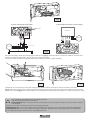
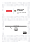
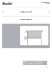
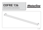
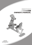
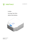
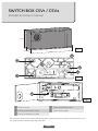
SWITCH BOX CSV1 / CSV2
Installer and User’s manual
72 mm
Fig.1
45 mm
162 mm
B
A
C
A
E
A
Fig.2
D
Fig.3
A Fixation holes
D Earth wire fixation hole
B Entry for the unlock cable
E
Earth wire output
C Entry for the electric cable
1▷ Prepare the output for the electric and unlock cables, respecting the preset sapaces on the switch box. Use
the 3 fixation holes to fix the switch box to the wall.
Fig.4
▷ Direct connection to the motor
▷ Connection with electric central board
Brake wire
FC
AP
COM
fase
fase
comum
CENTRAL
MOTOR
230V ~50 Hz
MOTOR
CENTRAL
Fig.5
2▷ Loosen the fixing screws of the push button and remove it (fig.4). Make the electric connection and pass the earth wire
terminal through the hole in fig.5, fastening it on the inside of the box.
The electric cables should have isolated terminal according to all electric safety standards.
Fig.6
Fig.7
3▷ Remove the screw present in the cable clamp using a 4mm hex wrench and insert the unlock cable on the hole
(fig.6). When the unlock cable is correctly stretched, tighten up the screw. Make sure that the motorreducer unlocks when
you push the handle (fig.7). If the motorreducer is not completely unlocked, adjust the tightener. Finally cut any excess cable.
The installation should be done by a qualified technician.
Keep this equipment away from children.
ELECTROCELOS S.A. is not responsible for the improper use of the product or other use than the one for which it
was designed.
Check the correct functioning of the operator and safety standards.
ELECTROCELOS S.A. is not responsible if safety standards were not taken into account when installing the equipment.
ELECTROCELOS S.A. is not responsible for the safety and proper operation when using components not sold by them.
In case of detecting any anomaly contact a qualified technician.