1
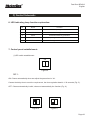
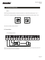
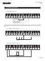
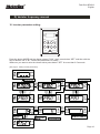
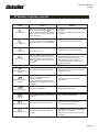
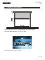
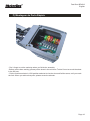
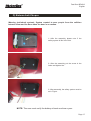
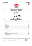
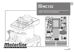
Fast Door BELOXI
English
Fast Door BELOXI
Installation Manual
Please read carefully before
any assembly or installation
VER.: 1.02
REV.: 12/2011
Fast Door BELOXI
English
A) Warning to installer and user
1) WARNING: It´s very important to your safety that this instructions are followed.The bad installation
or wrong appliance can damage people or materials.
2) Keep these instructions in a safe place for future reference.
3) This product was designed and produced strictly for the use indicated in this manual. Any other
use then expressly mentioned may damage the product and / or be a hazard to people, and void the
warranty.
4) ELECTROCELOS S.A. is not responsible for the incorrect use of the product or by using other than
that for which it was designed.
5) Do not install the product in an area where there is danger of explosion: gases or flammable fumes
are a serious security threat.
6) ELECTROCELOS S.A. is not responsible if the safety standards weren´t taken into account in the
manufacture of the element to be automated, or any deformation that may occur at the same.
7) Before the installation, turn off the power.
8) The devices (ex: photocells) should be used for prevent injury in people or materials.
9) ELECTROCELOS S.A. is not responsible for safety and proper operation of the product when isn´t
used components sold by itself.
10) Do not make any changes to the components of the engine and their accessories.
11)The installer should inform the customer of how to operate the product in an emergency case and
provide the manual of it.
12) Do not let the children closer to the door of the moving parts automatically when they are in
motion.
13) Keep controls out of reach of children, to prevent any accident.
14)You shouldn´t in any circumstances, attempt to repair or tune the automatic and must call an end
to this Technical qualified.
15) The automation should be installed to be protected from elements. Exposure to water, rain,
humidity or excessive dust may void the warranty of the product.
16) Connect the automatic taking of a protected 230 V with ground wire.
17) Automation for use inside.
Page 02
Fast Door BELOXI
English
B) Thechnical Specifications
.
1. Motor Specifications:
Model:
230V
Supply Voltage:
220V 50Hz
Electrical power:
750W
Insulation grade:
B
Hot protection:
Operation temperature:
Rotational speed:
130ºC
-20ºC a 40ºC
1440RPM
Outup torque:
15Nm
Frequency power:
750W
Diameter:
25mm
Biggest height of lift:
7m
2. Central Specifications:
Work power source:
Power input:
AC 230V 50Hz
1500W
Movement frequency:
20Hz - 120Hz
Ambient Temperature:
-10ºC a 55ºC
Relative humidity:
<70%
3. Sheet Specifications:
The fabric weight is 5000 x 5000 mm with a thickness of 0.8 mm.
The resistence is 3500 N/ 5cm following the BS 3424 norm.
The tear resistence is 600 N.
The working temperature is -30 ºC +70ºC.
The light resistence is 7 (except white sheet), following the BS 3424 norm.
The form to achive the termic isolantion is K.A/L=67 Wm2 K
Page 03
Fast Door BELOXI
English
C) Central Schematic
4. Central Schematic:
11
1
10
5
2
9
3
8
4
6
7
1 Air switch
5 Display
9 Close button
2 Brake Resistance
6 Central switch
10 Pause button
3 Frequency changers
7 Emergency stop switch
11 Opne button
4 Control circuit
8 Control box lock
Figure 1 - Control box scheme
Alernating current
supply input
Air Switch
Frequency
changer
Control Panel
Motor
Figure 2 - Control box wiring diagram
Page 04
Fast Door BELOXI
English
C) Central Schematic
J1
J2
AC220V N
J4
J3
CS
MAGNET
OS
PT
CL
OL
COM
STF STR M2 M1 MO SD SO SE
OPEN STOP CLOSE COM
F1
LED2 LED3 LED4 LED5 LED6
S1
MANUAL
AUTO
T1
LED11 LED10 LED9 LED8 LED7
VR1
MCU
LED2 LED1
AC1
AC2
COM PHOTO OPEN STOP CLOSE GND DTOP LOCK PUSH
J6
NC
CO
NO
J5
J1 - AC 220V Input
J6 - Open/Close/Stop/Buttons
J2 - Electromagnetic brake output socket
S1 - DIP switch selector
J3 - Spacing input post
F1 - 2A fuse box
J4 - Frequency changer output terminal
T1 - Transformer
J5 - External connection control signal
Vr1 - Automatic closing time adjustment potentiometer
Figure 3 - Control circuit schematic drawing
5. Setting inverter parameters:
Parameter nº:
Name
Value
1
P.003
Base frequency
50 Hz
2
P.004
Opening speed
50 Hz
3
P.024
Closing speed
50 Hz
Page 05
Fast Door BELOXI
English
C) Central Schematic
6. LED indicating lamp function explanation:
Nº
Nome
Function
1
LED 7
Opening door
2
LED 8
Closing door
3
LED 9
Electrical machinery protection
4
LED 10
Opening door with deceleration
5
LED 11
Closing door with deceleration
7. Control panel establishment:
(1) DIP switch establishment
ON
1
2
Figure 4
DIP 1:
ON: Closes automatically when we adjust the pause time in Vr1.
Causes the delay time to meet the requirement, the time regulation band is 1-30 seconds (Fig. 5).
OFF: Closes automatically invalid, closes not automatically the function (Fig. 6).
ON
1
ON
2
Figure 5
1
2
Figure 6
Page 06
Fast Door BELOXI
English
C) Central Schematic
DIP 2:
PHOTO ON (infrared protection): Infrared connected in a contact NO (normally open) - Fig. 7.
PHOTO OFF (infrared protection): Infrared connected in a contact NC (normally closed) - Fig. 8.
ON
1
ON
2
Figure 7
1
2
Figure 8
Note: Must use always infrared protection.
8. Connections:
8.1 Infrared protector:
AC1
AC2
COM PHOTO OPEN STOP CLOSE GND DTOP LOCK PUSH
RECEPTOR
12VAC
NC
CO
NO
TRANSMISSOR
OUT
COM
Note: If in the gate body downward movement process this signal is effective time, the gate body stops and
returns to the upward movement immediately.
Page 07
Fast Door BELOXI
English
C) Central Schematic
8.2 Interlocking system:
AC1
AC2
COM PHOTO OPEN STOP CLOSE GND DTOP LOCK PUSH
NC
CO
NO
Interlocking system between two doors
Will need chain-like another hanger-on spacing condition switch turning on, may realize the double gate
chain-like Function, when another gate body is at opens the door the condition, will lock in this, is unable to
open.
8.3 Wiring for external control:
AC1
AC2
COM PHOTO OPEN STOP CLOSE GND DTOP LOCK PUSH
NC
CO
NO
Push switch Open/Stop/Close
Wall switch
8.4 Wiring for external receiver:
AC1
AC2
COM PHOTO OPEN STOP CLOSE GND DTOP LOCK PUSH
NC
CO
NO
RECEPTOR
CH
Page 08
Fast Door BELOXI
English
C) Central Schematic
8.5 Wiring diagram of limit switches:
Meets to the door opener interior micro-active switch/micromove switch/sensitive switch
PT
Opens the door the
spacing
OS
Electrical machinery
protection
Electrical machinery
protection
Opens the door the
deceleration
Closes the deceleration
CS
CL
OL
COM
Wiring diagram of limit switches (J3)
If the aceleration or desaceleration wasn´t correct please change the motor connections.
9. Common breakdown phenomenon and solution:
Breakdown phenomenon
Electrical machinery two
directions cannot rotate
Reason
- Frequency changer or control
panel radio
- Electrical machinery hot
protection swith movement
Solution
- The replacement insurance,
inspects the power source.
Connect the line
- After waiting the temperature
reduces, the electrical machinery
to move again
The electrical machinery opens
the door normally, closes cannot
move
- Problem in the infrared
- According to above explanation
correct connection
The electrical machinery
changes opposite
- According to the scene
request, Electrical machinery
revolution direction needs
adjustment
- Electrical machinery output terminal
the U-V-W random two lines
exchange, and pays attention
decelerates, limits the position
switch's direction is whether normal
The electrical machinery
revolves stops, the frequency
changer display monitor
demonstrates wrong harms
code OC, OU, OH, OL, Ol1,
OCR.
- The load is overweight,
surpasses the frequency
changer peak power output
- Brakes the resistance not to
connect
The electrical machinery has not
decelerated the stop
- On electrical machinery's
deceleration switch is away from
improper with the limit switch.
- Choice power big frequency
changer
- Brakes the resistance
connection to be correct
- According to requests to
readjust deceleration, limit switch
Page 9
Fast Door BELOXI
English
D) Variator frequency manual
10. Inverter parameter setting:
PU
MON
RUN
Hz
V A
EXT
MODE
FWD
SET
REV
DU 03
STOP
RESET
Digital Unit
Press the button MODE and the display shows “P.000”. Next, press button “SET” and then with the
help of buttons “▲" e "▼", choose the parameters to modify.
Whenever you want to save the chosen value press button ”SET” for more than 0.5 seconds.
(See page 5 - Setting inverter parameters)
Page 10
Fast Door BELOXI
English
Variator frequency manual:
D) Variator frequency manual
11. Errors (Inverter):
Code
Cause
1. Under-voltage for power supply
2. RES terminal is connecter
3. Bad connection between the
manipulator and the main machine
4. Internal circuit malfunction
5. Wrong operation of CPU
1. Provide a normal power supply
2. Shut off RES
3. Ensure firm connection between the
manipulator and the main machine
4. Replace the inverter
5. Restart the inverter
The output current is two times
larger than the rated current of
the inverter
1. In case the time for acceleration or
deceleration is too short, prolong it
2. Avoid abrupt increase of load
3. Check terminals U, V and W for short
circuit
Over-current during
acceleration
Over-current at constant
speed
Solution
Over-current during
deceleration
Over-voltage during
acceleration
Over-voltage at constant
speed
Over-voltage between Terminal
P and Terminal N
1. In case the time for acceleration or
deceleration is too short, prolong it
2. Check the brake resistor between terminal
I and PR for loose connection
3. Check wether the values of Pr30 and Pr70
are right or not
Over-voltage during
deceleration
The IGBT moule is
overheating
Motor overheating
The brake transistor is
abnormal
The IGBT module thermal
accumulating relay acts
The electronic thermal relay
operates
The brake transistor is abnormal
Avoid the inverter long timely perating under
overload condition
1. Check wether the setting value of the Pr9
is correct or not (the setting should comply
the actual motor)
2. Reduce the load
Please send it back to the factory
Page 11
Fast Door BELOXI
English
ariator frequency manual:
D) Variator frequency manual
Code
Cause
Solution
When the output current is larger than
the set value, it will display
to
indicate that the inverter is in current
stall mode. In this case the motor may
not run smoothly.
1. Check if the values of Pr22, Pr23, Pr66
are proper
2. Check if the values of Pr7 and Pr8 are
too small
When the voltage between P and N is
too high, the inverter will display
.
The motor may not run smoothly.
1. Add a brake resistor between P and Pr
2. Check with the specified voltage
LV - Low voltage
Input voltage is low
1. Supply with the specified voltage
OLT - LT motion
When the output current is more than
twice the rated current, but ir doen’s
reach the stall level, the inverter will
display
. The motor may not run
smoothly.
1. Please increase the
acceleration/deceleration time in case of
abrupt acceleration/deceleration
2. Avoid abrupt load increasing
3. Check wether there is short circuit
among U, v and W
The external thermal relay operates
1. Check the capacity of the external
thermal relay and the motor for matching
2. Reduce the load
1. Abnormal communication. The
maximum communication retry
number is violated.
2. Interrupted communication. The
maximum communication check time
is violated.
Correctly set the communication
parameters
The memory ROM fails.
Send it back to the factory
External electromagnetic disturbance is
too strong
Improve external disturbance
The load of the motor is too heavy
1. Reduce the load of the motor
2. Increase the value of Pr22
The temperature of IGBT module is
too high
1. Reduce the environment temperature
and improve air condition
2. Check wether the fan of the inverter is
damaged
OLI - Current stall
OLV - Voltage stall
The external thermal relay
operates
Peripheral devides are
abnormal
Memory is abnormal
CPU error
Stall prevention protection
IGBT module is too hot
Page 12
Fast Door BELOXI
English
E) Esquema da Porta Rápida
4
5
1
14
18
3
4
6
17
15
16
7
2
8
13
9
12
19
19
11
1 - Drum
2 - Electronic table
3 - Nylon
4 - Ear-muff Support
5 - Axle bushing
6 - Separator medium-reducer
7 - Aluminum Guide
8 - PVC tarpaulin
9 - Photocell mirror with stand
10 - Counterweight with security system
10
11 - Scooter slider
12 - Photocell with support
13 - NOT applied
14 - Axis covers
15 - Reducer
16 - Motor
17 - Limit switch box
18 - Axle short
19 - Photocell support
Page 13
Fast Door BELOXI
English
F) Montagem da Porta Rápida
1-The door is placed vertically
2-After setting the medium, it can be
level the sheet through the screw that
you see in the image
3- Place fixing screws to the floor in
the support
4- Use the handle to unlock the door
Page 14
Fast Door BELOXI
English
Assembly:da Porta Rápida
F) Montagem
X
X + 1cm
- You should be careful to place 1 cm off the bottom of the door, as a safety measure.
- Must be sure that the sheet enter 5 cm in each side the tab.
-Don´t forget to link the earth wire to the screw.
Page 15
Fast Door BELOXI
English
F) Montagem da Porta Rápida
- Don´t forget to set the end-stop when you finish the assembly.
- Before put the door working, please put the sheet in the mid-term. To don´t force too much the sheet
in the first use.
- Put the function selector in JOG position and start to rise the door and fall the same, until you reack
the limit. When you achive that point, please screw the selector.
Page 16
Fast Door BELOXI
English
G) Sistema Anti-Choque
Warning (anti-shock system): System created to save people from the collision
between them and the door when the door is on motion.
1- After the assembly, please note if the
safety system is like in the foto.
2- After the assembly put the screw in the
linker and tighten him.
3- After assembly, the safety system must be
as in Figure.
NOTE: The user must verify the battery at least one time a year.
Page 17