1
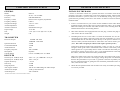
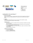
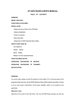
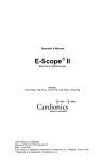
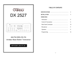
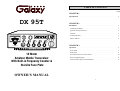
TABLE OF CONTENTS
PAGE
CHAPTER 1
Specifications . . . . . . . . . . . . . . . . . . . . . . . . . . . . . . . . . . . . . . . . . . . . . .
DX 95T
B IG R IG S E R IE S
D
E
C
S
1
9
5 7
3
+20
80
60
40
+4 0 dB
+6
0
10 0
F
PA
B
G
A
H
AM
CHAPTER 2
U SB
LSB
%
20
M OD
40 60 8
0
20
10
H IG H SW R ALERT
10 0
M
PW R 0
SW R
FM
1.5
2
3
MO D
AX
RB
O FF
1
SW R
PW R
DX 95T
O FF
SQ
M IC
PU SH
TB O FF
O FF
+10KH z
40dB
PAD
GN F
VO L
MO D
LAM P
O FF
EC H O
TB
D IM
PU SH
F.D ISP O FF
5/6 D IG IT
O FF
RX /TX
PO W ER
FIN E
2
NB
AN L
Installation . . . . . . . . . . . . . . . . . . . . . . . . . . . . . . . . . . . . . . . . . . . . . . . .
3
Installing The Radio . . . . . . . . . . . . . . . . . . . . . . . . . . . . . . . . . . . . . . . .
3
Ignition Noise Interference . . . . . . . . . . . . . . . . . . . . . . . . . . . . . . . . . . .
4
Antenna . . . . . . . . . . . . . . . . . . . . . . . . . . . . . . . . . . . . . . . . . . . . . . . . . .
4
External Speaker . . . . . . . . . . . . . . . . . . . . . . . . . . . . . . . . . . . . . . . . . . .
4
Public Address . . . . . . . . . . . . . . . . . . . . . . . . . . . . . . . . . . . . . . . . . . . .
4
PAD
RX
C O ARSE
PU SH
N B/AN L
10 Meter
Amateur Mobile Transceiver
With Built-in Frequency Counter &
StarLite Face Plate
CHAPTER 3
Operation . . . . . . . . . . . . . . . . . . . . . . . . . . . . . . . . . . . . . . . . . . . . . . . . .
5
Front Panel . . . . . . . . . . . . . . . . . . . . . . . . . . . . . . . . . . . . . . . . . . . . . . .
5
Rear Panel . . . . . . . . . . . . . . . . . . . . . . . . . . . . . . . . . . . . . . . . . . . . . . . .
9
Procedure to Receive and Transmit . . . . . . . . . . . . . . . . . . . . . . . . . . . .
10
Receiving SSB Signals . . . . . . . . . . . . . . . . . . . . . . . . . . . . . . . . . . . . . .
11
Alternate Microphone and Installation . . . . . . . . . . . . . . . . . . . . . . . . . .
13
OWNER’S MANUAL
1
CHAPTER 1 SPECIFICATIONS
GENERAL
Model
Frequency Range
Emission
Frequency Control
Frequency Stability
Temperature Range
Antenna Impedance
Antenna Connectors
Input Voltage
Size
Weight
Spurious Emission
Unwanted Sideband
Audio Distortion
Frequency Response
Microphone
Clarifier Range
INSTALLING THE RADIO
DX 95T
28.315 ~ 28.755 MHz
FM/AM/USB/LSB
Phase-Lock-Loop (PLL) Synthesizer
0.001%
-30°C to +50°C
50 Ohms
Standard SO-239 type
13.8V DC
Choose a convenient location for operation that does not interfere with driver or
passenger. This radio is supplied with a universal mounting bracket. When mounting
the bracket and radio to your car, make sure it is mechanically strong. Also, provide a
good electrical grounding connection to the chassis of vehicle. Proceed as follows to
install the radio.
7 3/4" (W) x 2 7/8" (H) x 10 1/4" (D)
6 lb.
2.
Most radio antennas come equipped with a PL-259 plug. Connect this plug to the
ANT. Jack in the rear of the radio.
3.
Extending from the rear of the radio is a fused red and black wire for the DC
connections to the vehicle’s electrical system. For best performance, it is strongly
recommended that the red lead be taken directly to the positive terminal on the
vehicle’s battery and the black lead be connected to the nearest chassis ground.
(Note: This radio is designed for vehicles with negative ground systems.)
TRANSMITTER
RF Power Output
CHAPTER 2 INSTALLATION
1. Locate a convenient area in your vehicle for the installation of the radio. Hold the
mounting bracket with the radio in the location where the radio is to be installed.
Make sure nothing will interfere with either the radio or the mounting bolts. Mark
and then drill holes for the mounting bracket.
AM/FM: 2W~50W
USB/LSB: 150W PEP
-50 dB
-50 dB
10%
300 to 2500Hz
Dynamic
Coarse: ± 6.0KHz, Fine: ± 1.0KHz
Connections should be made using appropriate “crimp on” lugs of a size large
enough to make good contact with the bolt used to fasten to the battery and the
chassis ground. It is a good safety idea to install a second fuse that would provide
protection in case the red wire was to “fray” or get pinched and short to the body of
the vehicle, somewhere between the battery and the radio.
RECEIVER
Sensitivity for 10 dB (S+N)/N
Sensitivity for 12 dB (S+N)/N
Squelch Sensitivity
Selectivity
Image Rejection
AGC Figure of Merit
Audio Power Output
Audio Response
AM: < 0.5 µV; USB/LSB: < 0.25 µV
FM: < 0.25 µV
< 0.5 uV
-55 dB
-50 dB
100 mV for 10dB Change in Audio Output
2.5W @ 10% Distortion
300 to 2500 Hz
High power radios such as this one require large DC current flow when in the TX
mode. Poor power connections cause supply voltage drops that can substantially
decrease the performance of your radio. A good DC connection is probably one of
the most important things for getting the best transmitter performance and in some
cases, least receiver noise.
4.
Mount the microphone bracket near the radio in an easily accessible spot using the
two screws provided.
(SPECIFICATIONS SUBJECT TO CHANGE WITHOUT NOTICE)
2
3
IGNITION NOISE INTERFERENCE
With weak signals, you may experience interference of the signal by background
noise. This radio has NB and ANL circuits which will help reduce background noise
from sources such as your ignition system. However, background electrical noise may
come from several sources and all noise may not be eliminated. With extremely weak
signals, you can operate this radio with the engine turned off, which should improve
reception. If the ignition noise level is too high to allow proper operation under most
conditions, you should have your installation of the radio checked by a qualified
technician.
CHAPTER 3 OPERATION
CONTROL FUNCTIONS
FRONT PANEL
14
15 16 17 18 19 20
B IG R IG S E R IE S
D
E
C
ANTENNA
This radio has a jack in the rear for a standard PL-259 antenna plug. If you are
looking for the most range for your transmission, use a vertically polarized, quarterwave length antenna. If antenna height is a problem, you may use a shorter, loaded-type
whip antenna although you can expect some loss of transmission range.
To improve performance, your antenna should be matched to your radio. Your
antenna can be adjusted so that it matches your radio.
S
1
9
5 7
3
60
+20
80
10
20
+4
0 + dB
60
10 0
40
20
M OD
4 0 60 8
0
PW R
SW R
2
1.5
PA
AM
22 23 24 25
U SB
LSB
G
A
H
%
H IG H SW R ALERT
10 0
M
0
FM
F
B
21
3
MOD
AX
RB
O FF
1
SW R
PW R
DX 95T
SQ
M IC
PU SH
TB O FF
O FF
O FF
+10KH z
40dB
PAD
GN F
VO L
MOD
LAM P
O FF
ECH O
TB
5/6 D IG IT
O FF
PU SH
F.D ISP O FF
PO W ER
FIN E
PAD
RX
RX/TX
D IM
NB
AN L
C O ARSE
PU SH
N B/AN L
EXTERNAL SPEAKER
The external speaker jack (EXT SP.) on the rear panel is used for remote receiver
monitoring. The external speaker should have 8 ohms impedance and be able to handle
at least 4 watts. When the external speaker is plugged in, the internal speaker is
disconnected.
PUBLIC ADDRESS
To use the Public Address (PA) function, first connect an external speaker to the PA.
SP. Jack on the rear of the radio. See the above specifications for a proper external
speaker. Keep the speaker away from the microphone to avoid acoustic feedback.
1
2
3
4
5
6
7
8
9 10 11 12
13
1. MOD LAMP: When switched on, this Modulation indicator will illuminate as you
speak into the microphone. When you speak louder, it appears bright because it is
on nearly 100 percent of the time and when you speak softer, it appears dimmer
because it is flickering on and off. It does not glow at all when there is no
modulation. This lamp operates in all modes.
2. SWR/MOD/PWR SWITCH: This switch controls the function of the meter
during the transmit mode. In the “SWR” position, the meter indicates the Standing
Wave Ratio (SWR) of your antenna (accurate at maximum power output). There
are no adjustments because the SWR circuit in this radio calibrates itself
automatically. When the switch is in the “MOD” position, the green scale on the
meter indicates your percentage of modulation in the AM mode only. It is most
accurate when testing at maximum power output. When this switch is in “PWR”
position, the meter indicates your power output.
3. MICROPHONE JACK: Used to connect microphone.
4. ON/OFF VOLUME CONTROL: This knob controls the volume and power to the
radio. To turn radio on, rotate the knob clockwise. Turning the knob further will
increase the volume of the receiver.
4
5
5. SQUELCH CONTROL: This knob is used to eliminate background noise being
heard through the receiver, which can be disturbing when no transmissions are
being heard through the receiver. To use this feature, turn the knob fully
counterclockwise and then turn clockwise slowly until the background noise is just
eliminated. Further clockwise rotation will increase the threshold level which a
signal must overcome in order to be heard. Only strong signals will be heard at a
maximum clockwise setting.
14. FRONT PANEL METER: The front panel meter allows the user to monitor
incoming signal strength, RF output power, SWR level and AM modulation level.
6. MIC GAIN CONTROL/PUSH TB OFF SWITCH: Adjusts the microphone gain
in transmit and PA modes. This controls the gain to the extent that full talk power is
available several inches away from the microphone. In the Public Address (PA)
mode, the control functions as the volume control. Pushing this knob turns the
Talkback circuit on and off.
16. BAND SELECTOR: This switch is used to select the band.
7. TALKBACK (TB) CONTROL: Adjust this knob for desired volume of Talkback.
This is used to monitor your own voice. For example, you could use this feature to
compare different microphones.
8. DIM CONTROL/PUSH FREQUENCY DISPLAY OFF SWITCH: This knob
controls the level of brightness for the meter lamp, faceplate, frequency display and
channel display. Pushing this knob turns the Frequency Display on and off
9. RF POWER CONTROL: This control allows the user to adjust RF power output.
10. COARSE/FINE CONTROL/PUSH NB-ANL OFF SWITCH: Allows variation
of the radio operating frequencies above and below the channel frequency.
Although this control is intended primarily to tune in SSB signals, it may be used to
optimize AM/FM signals. Pushing this knob turns the Noise Blanker (NB) /
Automatic Noise Limiter (ANL) circuit on and off. The Noise Blanker (NB) is very
effective in eliminating repetitive impulse noise such as ignition interference.
11. RX/TX/OFF/RX SWITCH: When in the RX/TX position, the two clarifiers
(Coarse and Fine) function on both receive and transmit. When the switch is in the
RX position, the Fine clarifier functions on receive only and the Coarse clarifier
still functions on both receive and transmit. When in the OFF position, both
clarifiers have no effect on the frequency.
12. CHANNEL SELECTOR: This control is used to select the desired transmit and
receive channel.
13. GNF LED: This LED lights green when the GNF function is on.
6
15. ILLUMINATED FACE PLATE: All faceplate lettering will fully illuminate to
allow the user easy viewing at night. This unique, solid state, backlight is designed
to maximize night vision while minimizing eye fatigue. Therefore, it is ideal for
switch and control recognition day or night.
17. RB/OFF/ECHO SWITCH: When in the RB position, the radio transmits an audio
tone at the end of your transmission to indicates that transmission has ended. As a
courtesy to others, use the Roger Beep only when necessary. When the switch is in
the ECHO position it turns the Echo circuit on. The time and amount of Echo effect
are preset at the factory. There are no external controls for these adjustments.
However, there are two small internal adjusting pots inside the Echo module, which
is located in a metal box just behind the channel selector switch. These adjusting
pots are labeled Echo and Time.
18. MODE SWITCH: This control allows you to select one of the following operating
modes: PA/FM/AM/USB/LSB.
19. GNF/OFF/40dB PAD SWITCH: When in the GNF position, the Galaxy Noise
Filter is activated. This is a special noise filter that de-emphasizes audio high
frequency response in order to increase the signal-to-noise ratio of weak signals.
While you will notice a dramatic reduction in the “rushing” sound when this filter
is activated, it does not have much effect on the signal-to-noise ratio of strong
signals. The GNF is for SSB use only and will cause distortion if used during AM
reception. When the switch is in the 40dB PAD position, the 40dB attenuation
circuit is activated. When the switch is in the OFF position, neither the GNF circuit
nor the Attenuation circuit will be active.
20. MOD LAMP/OFF/+10KHz SWITCH: When in the MOD LAMP position, the
Mod Lamp circuit is activated. When the switch is in the +10KHz position, the
frequency is shifted up 10KHz.
21. FREQUENCY COUNTER: This display indicates the frequency of the selected
channel.
22. 5/6 DIGIT SWITCH: Pushing this switch will change the frequency display from
a six digit readout to a five digit readout. It will turn the hundreds digit on and off.
Then a frequency of 28.3056 MHz would read 28.305 MHz.
7
23. NB/ANL LED: This LED lights green when the NB/ANL circuit is on.
REAR PANEL
24. CHANNEL DISPLAY: The channel display indicates the current selected channel.
3
25. PAD LED: This LED lights green when the 40dB attenuator circuit is on.
4
NOTES
HIGH SWR ALERT: All three LEDs (NB/ANL, GNF & PAD) light red when your
SWR is higher than about 3:1. This alert is accurate only at
maximum power output. This is not an exact indicator of 3:1
SWR, but it is an indication that you should check your SWR
reading.
1
2
1. ANTENNA: This jack accepts a 50-ohm coaxial cable with a PL-259 type plug.
2. DC POWER: This jack accepts the 13.8V DC power cable with built-in fuses. The
power cord provided with the radio has a black and red wire. The black goes to
negative and red goes to positive.
3. PA SP: This jack is for PA operation. Before operating, you must first connect a
PA speaker (8 ohms, 4W) to this jack.
4. EXT. SP: This jack accepts a 4 to 8 ohm, 5-watt external speaker. When the
external speaker is connected to this jack, the built-in speaker will be disabled.
8
9
PROCEDURE TO RECEIVE AND TRANSMIT
RECEIVING SSB SIGNALS
A. MICROPHONE
The push-to-talk switch on the microphone controls the receiver and transmitter. Press
the switch and the transmitter is activated, release switch to receive. When transmitting,
hold the microphone two inches from your mouth and speak clearly in a normal voice.
This transceiver comes complete with a low impedance dynamic microphone.
There are four types of signals presently used for communications: FM, AM, USB
and LSB. When the MODE switch on your unit is placed in the AM position, only
standard double-side band and in FM position, only frequency deviation, full carrier
signals will be detected. An SSB signal may be recognized while in the AM or FM
mode by its characteristic "Donald Duck" sound and the inability of the detector to
produce an intelligible output. The USB and LSB modes will detect upper sideband and
lower sideband respectively, and standard AM signals.
B. PROCEDURE TO RECEIVE
1. Be sure that power source, microphone and antenna are connected to the proper
connectors before going to the next step.
2. Turn VOL knob clockwise to apply power to the radio.
3. Set the VOL for a comfortable listening level.
4. Set the MODE switch to the desired mode.
5. Listen to the background noise from the speaker. Turn the SQ knob slowly
clockwise until the noise just disappears. The SQ is now properly adjusted. The
receiver will remain quiet until a signal is actually received. Do not advance the
control too far or some of the weaker signals will not be heard.
6. Set the CHANNEL selector switch to the desired channel.
7. Adjust COARSE/FINE control to clarify the SSB signals or to optimize AM/FM
signals.
C. PROCEDURE TO TRANSMIT
1. Select the desired channel of operation.
2. Set the MIC GAIN control fully clockwise.
SSB reception differs from standard AM reception in that an SSB receiver does not
require a carrier or opposite side band to produce an intelligible signal. A single-side
band transmitted signal consists only of the upper or the lower side band and no carrier
is transmitted. The elimination of the carrier from the AM signal helps to eliminate the
biggest cause of whistles and tones heard on channels that make even moderately strong
AM signals unreadable. Also, SSB takes only half the space of an AM channel,
therefore two SSB conversations will fit into each channel, expanding the 40 AM
channels to 80 SSB channels. The reduction in channel space required also helps in the
receiver because only half of the noise and interference can be received with 100% of
the SSB signal.
An SSB signal may be received only when the listening receiver is functioning in the
same mode. In other words, an upper side band signal (USB) may be made intelligible
only if the receiver is functioning in the USB position.
If a lower side band (LSB) signal is heard when the receiver is in the USB mode, no
amount of tuning will make the signal intelligible. The reason for this may be
understood if you consider that when the modulation is applied to the transmitter's
microphone in the USB mode, the transmitter output frequency is increased whereas in
the LSB mode the transmitter's output frequency is decreased.
3. If the channel is clear, depress the push-to-talk switch on the microphone and speak
in a normal voice.
The result in listening to the receiver is that when the MODE switch is in the proper
position (either USB or LSB), a true reproduction of a single tone of modulation will
result, and if the tone is increased in frequency (such as a low-pitched whistle or a highpitched whistle) you will hear the increase in the output tone of the receiver. If the
incorrect mode is selected, an increase in tone of a whistle applied to the transmitter
will cause a decrease in the resultant tone from the receiver.
10
11
Thus when a voice is used in place of a whistle or tone, in the proper listening mode
the voice will be received correctly whereas in the incorrect mode, the voice will be
translated backwards and cannot be made intelligible by the COARSE/FINE control.
When listening to an AM transmission, a correct side band is heard in either mode since
both upper and lower side bands are received.
Once the desired SSB mode has been selected, frequency adjustment may be
necessary in order to make the incoming signal intelligible. The COARSE/FINE control
allows the operator to vary frequency above or below the exact frequency of the
channel. If the sound of the incoming signal is high or low pitched, adjust the operation
of the COARSE/FINE.
Consider it as performing the same function as a phonograph speed control. When the
speed is set too high, voices will be high-pitched and if set too low, voice will be lowpitched. Also, there is only one correct speed that will make a particular record produce
the same sound that was recorded. If the record is played on a turntable that is rotated in
the wrong direction (opposite side band) no amount of speed control (COARSE/FINE)
will produce an intelligible sound.
An AM signal received while listening in one of the SSB modes will produce a steady
tone (carrier) in addition to the intelligence, unless the SSB receiver is tuned to exactly
the same frequency by the COARSE/FINE control. For simplicity, it is recommended
that the AM modes be used to listen to AM signals.
ALTERNATE MICROPHONES AND INSTALLATION
For best results, the user should select a low-impedance dynamic type microphone or
a transistorized microphone. Transistorized type microphones have low output
impedance characteristics. The microphones must be provided with a four-lead cable.
The audio conductor and its shielded lead comprise two of the leads. The third lead is
for transmit control and fourth is for receiving control.
The microphone should provide the functions shown in the schematic below.
4 WIRE MIC CABLE
Pin Number
Mic Cable Lead
1
Audio Shield
2
Audio Lead
3
Transmit Control
4
Receive Control
Fig. 1 Your transceiver microphone schematic.
If the microphone to be used is provided with pre-cut leads, they must be revised as
follows.
1. Cut leads so that they extend 7/16" beyond the plastic insulating jacket of the
microphone cable.
2. All leads should be cut to the same length. Strip the ends of each wire 1/8" and tin
the exposed wire.
12
13
Before beginning the actual wiring, read carefully the circuit and wiring information
provided with the microphone you select. Use the minimum heat required in soldering
the connections. Keep the exposed wire lengths to a minimum to avoid shorting when
the microphone plug is reassembled.
5. The wires must now be soldered to the pins as indicated in the above wiring tables.
If a vise or clamping tool is available it should be used to hold the pin receptacle
body during the soldering operation, so that both hands are free to perform the
soldering. If a vise or clamping tool is not available, the pin receptacle body can be
held in a stationary position by inserting it into the microphone jack on the front
panel. The numbers of the microphone plug are shown in Fig. 3, as viewed from
the back of the plug. Before soldering the wire to the pins, pre-tin the wire
receptacle of each pin of the plug.
Fig. 3 Microphone plug pin numbers viewed from rear of pin receptacle.
6. Be sure that the housing and the knurled ring of Figure 2 are pushed back onto the
microphone cable before starting to solder. If the washer is not captive to the pin
receptacle body, make sure that it is placed on the threaded portion of the pin
receptacle body before soldering.
Fig. 2 Microphone plug wiring
To wire the microphone cable to the plug provided, proceed as follows:
1. Remove the retaining screw.
2. Unscrew the housing from the pin receptacle body.
3. Loosen the two cable clamp retainer screws.
4. Feed the microphone cable through the housing, knurled ring and washer as shown
Figure 2.
14
7. If the microphone jack is used to hold the pin receptacle during soldering operation,
best results are obtained when the connections to pin 1 and 3 are made first and
then the connections to pins 2 and 4. Use a minimum amount of soldering and be
careful to prevent excessive solder accumulation on pins, which could cause a short
between the pin and the microphone plug housing.
8. When all soldering connections to the pins of the microphone are completed, push
the knurled ring and the housing forward and screw the housing onto the threaded
portion of the pin receptacle body. Note the location of the screw clearance hole in
the plug housing with respect to the threaded hole in the pin receptacle body. When
the housing is completely threaded into the pin receptacle body, a final fraction of a
turn either clockwise or counterclockwise may be required to align the screw hole
with the threaded hole in the pin receptacle body. When these are aligned, the
retaining screw is then screwed into place to secure the housing to the pin
receptacle body.
15
9. The two cable clamp retainer screws should now be tightened to secure the housing
to the microphone cord. If the cutting directions have been carefully followed, the
cable clamp should secure to the insulation jacket of the microphone cable.
MEMO
10. Upon completion of the microphone plug wiring, connect and secure the
microphone plug in the transceiver.
16
17
- 13 -
WARRANTY
This radio is covered by a two
year Limited parts and labor
warranty.
“Limited” means that we will repair problems caused by factory defects or normal
use at no charge.
Before returning a radio to us for warranty service, please call our Service
Department for a Repair Authorization Number (RAN). This RAN must be written
below your return address on the outside of the shipping box. Boxes, which arrive
without an RAN, will be refused, and the shipping company will return the
unopened box to you. Be sure to have a pen and paper ready along with the serial
number of your radio before calling. We will give you the RAN and our shipping
address over the phone. The telephone number of the Service Department is (760)
480-8800, and we suggest calling between 10:00 AM and 4:00 PM Pacific Time.
Please include a note with a detailed description of the symptoms. This is important
because it will help the technician who works on your radio to locate your problem.
Intermittent problems are easily overlooked, so be sure to give as much detail as
possible in your note. Also, please include your daytime telephone number in case
our technicians have any additional questions.
Do not send your power cord or microphone unless we ask for these items during
our telephone conversation.
You are responsible for getting the radio safely to us. (We suggest using United
Parcel Service.) You must pay to ship the radio to us, and we will pay to ship the
radio back to you. Since we use UPS and they do not ship to Post Offices boxes,
please provide us with a street address for the return of your radio.
We will repair and return your radio as soon as we can. We appreciate your
choosing a Galaxy radio and we want you to be on the air as much as possible!
Be sure to visit our web site at
www.GalaxyRadios.com
18
Printed in Taiwan
AT0949010P
19