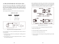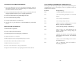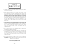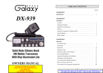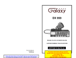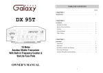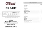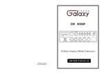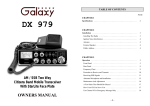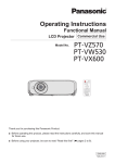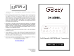
1
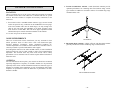
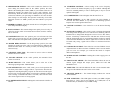
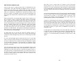
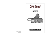
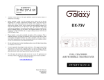
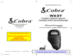
DX 2547
POWER
S
5
3
1
MOD
TALKBACK
3
PWR
0
SWR
1
7
40%
20%
6
2
1.5
9
+20
60%
9
80%
12
+40
100%
15
3
NORMAL
9
19
dB
+6
0
GNF R.B.
MA
X
CHANNEL
AM / SSB Base Station CB Radio
RX / TX
PA
USB
AM
ANL
NB
LSB
SWR ALERT
SQUELCH
DX 2547
OFF
PHONES
RF POWER
SWR MOD PWR
R. B.
ANL
NB
GNF
CLARIFIER
MIC
MIC
RF
DIM
TONE
PA
USB AM LSB
CLARIFIER
OFF
AM/ SSB Two Way
Citizen Band Base Station Transceiver
Printed In Malaysia
AT2547010A
PD0009028
OWNER’S MANUAL
VOLUME
TABLE OF CONTENTS
CHAPTER 1 SPECIFICATIONS
PAGE
CHAPTER 1
Specifications . . . . . . . . . . . . . . . . . . . . . . . . . . . . . . . . . . . . . . . . .
2
CHAPTER 2
Installation . . . . . . . . . . . . . . . . . . . . . . . . . . . . . . . . . . . . . . . . . . .
Location . . . . . . . . . . . . . . . . . . . . . . . . . . . . . . . . . . . . . . . . . . . .
Ignition Noise Interference . . . . . . . . . . . . . . . . . . . . . . . . . . . . . .
Antenna . . . . . . . . . . . . . . . . . . . . . . . . . . . . . . . . . . . . . . . . . . . . .
External Speaker . . . . . . . . . . . . . . . . . . . . . . . . . . . . . . . . . . . . . .
Phone Jack . . . . . . . . . . . . . . . . . . . . . . . . . . . . . . . . . . . . . . . . . .
Public Address . . . . . . . . . . . . . . . . . . . . . . . . . . . . . . . . . . . . . . .
3
3
3
3
5
5
5
GENERAL
Channels
Frequency Range
Emission
Frequency Control
Frequency Tolerance
Frequency Stability
Temperature Range
Antenna Impedance
Antenna Connectors
Meter Function
Input Voltage
40
26.965 ~ 27.405 MHz
AM/USB/LSB
Phase-Lock-loop (PLL) Synthesizer
0.005%
0.003%
-30°C to +50°C
50 Ohms
Standard SO-239 type
Meter#1 RF output Power / Antenna SWR
Meter#2 Received signal strength / MOD %
AC 120V, 60Hz
TRANSMITTER
CHAPTER 3
Operation . . . . . . . . . . . . . . . . . . . . . . . . . . . . . . . . . . . . . . . . . . . .
Control Function . . . . . . . . . . . . . . . . . . . . . . . . . . . . . . . . . . . . . .
Front Panel . . . . . . . . . . . . . . . . . . . . . . . . . . . . . . . . . . . . . . . . . .
Rear Panel . . . . . . . . . . . . . . . . . . . . . . . . . . . . . . . . . . . . . . . . . . .
Frequency Chart . . . . . . . . . . . . . . . . . . . . . . . . . . . . . . . . . . . . . .
Procedure to Receive And Transmit . . . . . . . . . . . . . . . . . . . . . . .
Receiving SSB Signals . . . . . . . . . . . . . . . . . . . . . . . . . . . . . . . . .
Alternate Microphone And Installation . . . . . . . . . . . . . . . . . . . .
Maintenance and Adjustment . . . . . . . . . . . . . . . . . . . . . . . . . . . .
A Few Rules That Should Be Obeyed . . . . . . . . . . . . . . . . . . . . .
How Your CB can Serve You . . . . . . . . . . . . . . . . . . . . . . . . . . . .
Use Channel 9 for Emergency Message Only . . . . . . . . . . . . . . .
Warranty . . . . . . . . . . . . . . . . . . . . . . . . . . . . . . . . . . . . . . . . . . . .
-1-
6
6
6
10
11
12
13
15
18
19
19
20
21
RF Power Output
Antenna Connector
AM Modulation
Spurious Emission
Unwanted Sideband
AM 4W ; USB/LSB 12W PEP
UHF Type, 50 Ohms
Up to 100%
Better than -60 dB
Better than -60 dB
RECEIVER
Sensitivity for 10 dB (S+N)/N
Adjacent Channel Rejection
Image Rejection
AGC Figure of Merit
Audio Power Output
Audio Response
AM : 0.5 uV, USB/LSB : 0.15 uV
-60dB
-50dB
50 mV for 10dB Change in Audio Output
2.5W @ 10% Distortion
300 to 2500 Hz
-2-
CHAPTER 2 INSTALLATION
LOCATION
1. Vertical Ground Plane Antenna : Omni directional antennas provide
optimum performance for contacting other fixed stations using vertical
type antennas in addition to all mobile stations. For medium long range
communications work.
Choose a location close to an AC power outlet and convenient for running
the antenna lead-in cable. This transceiver is attached with the AC power
cord set. Proceed as follows to complete all necessary connections to the
transceiver.
1. Your transceiver has a standard antenna connector type, SO-239 located
on the rear panel for easy connection to the standard PL-259 coax plugs.
If the coax antenna cable must be made longer, use only enough coax
cable to suit your needs with impedance of 50 ohms, frequency range
from 26.965 to 27.405 MHz. This will insure proper impedance match
and maximum power transfer from the transmitter to the antenna.
2. Use 120V AC power for the base station.
NOISE INTERFERENCE
There are several kinds of noise interference you may encounter in base
station operation. Some of these noises come from fluorescent light,
electrical appliance, lawnmower, nearby commercial broadcast etc.
Commercial products are available to reduce interference from these sources.
Consult your dealer or professional amateur radio supplier.
Even though the transceiver has ANL and NB controls, in some installation
ignition interference may be high enough to make good communications
impossible. The electrical noise may come from several sources. Many
possibilities exist as variations between vehicles require different solutions to
reduce the noise.
Ground Plane
2. Directional Beam Antenna : Highly efficient and directional antenna
generally intended for fixed-to-fixed long range communications.
ANTENNA
For best transmission and reception, your transceiver should use an antenna
especially designed for a frequency of 27 MHz. Antenna is to be purchased
separately and it comes with the installation instructions. Numerous types of
antennas are available. Some emphasize on ease of installation while others
emphasize on performance. Often the difference in performance for these
antennas is modest.
Directional Beam Antenna
-3-
-4-
EXTERNAL SPEAKER
The external speaker jack (EXT. SP.) on the rear panel is used for remote
receiver monitoring. The external speaker should have 8 ohms impedance
and be able to handle at least 4 watts. When the external speaker is plugged
in, the internal speaker is disconnected.
CHAPTER 3 OPERATION
CONTROL FUNCTIONS
FRONT PANEL
PHONE JACK
This PHONE jack accepts headphone of 4 to 32 ohms impedance. When a
headphone is plugged into this jack, both internal and external speakers are
silenced simultaneously.
POWER
S
PUBLIC ADDRESS
1
5
3
To use the transceiver as a public address system, connect an external 8 ohms
speaker (4 watts minimum) to the PA. SP. jack located on the rear panel.
Direct speaker away from the microphone to prevent acoustic feedback.
Physical separation or isolation of the microphone and speaker is important
when operating the PA at high output levels.
MOD
TALKBACK
SWR
1
1.5
+20
60%
9
6
3
PWR 0
9
7
40%
20%
2
80%
12
+40
100%
15
3
NORMAL
19
9
dB
+6
0
GNF R.B.
MA
X
PA
CHANNEL
AM / SSB Base Station CB Radio
RX / TX
USB
AM
ANL
NB
LSB
SWR ALERT
SQUELCH
DX 2547
OFF
PHONES
RF POWER
SWR
MOD
PWR
R. B.
ANL
NB
GNF
CLARIFIER
MIC
MIC
RF
DIM
TONE
USB AM
PA
LSB
CLARIFIER
VOLUME
OFF
1. PHONE JACK : Used to connect headphones for listening.
2. MICROPHONE JACK : Used to connect microphone for voice source.
3. RF POWER CONTROL : This control allows the user to adjust RF
power output.
4. RF GAIN CONTROL : This control is used to reduce the gain of the RF
amplifier under strong signal conditions.
5. MIC GAIN CONTROL : Adjust the microphone gain in the transmit and
PA modes. This controls the gain to the extent that full talk power is
available several inches away from the microphone. In the Public
Address (PA) mode, the control function as the volume control.
-5-
-6-
6. SWR/MOD/PWR SWITCH : This switch controls the function of the
meter during the transmit mode. In the “SWR” position, the meter
indicates the Standing Wave Ratio (SWR) of your antenna. There are no
adjustments because the SWR circuit in this radio calibrates itself
automatically. When the switch is in the “MOD” position, the green scale
on the meter indicates your percentage of modulation. It is most accurate
when testing at 4 watts output. This operates in AM only, not in SSB.
When this switch is in “PWR” position, the meter indicates your power
output.
7. DIMMER CONTROL : This knob controls the level of brightness for the
meter lamp and channel display.
8. TONE CONTROL : This control changes tone quality in receive only. In
clockwise rotation, treble is increased and in counter clockwise rotation,
bass is increased.
9. PA/OFF SWITCH : In the “PA” position, your voice will come out of the
speaker that you need to plug in to the “PA.SP” jack on the back of the
radio. The radio does not operate when you are in the “PA” mode.
10. ROGER BEEP SWITCH : In the Roger Beep position, the radio
transmits an audio tone at the end of your transmission to indicates that
transmission has ended. As a courtesy to others, use the Roger Beep only
when necessary.
11. CHANNEL SELECTOR : This control is used to select a desired
transmit and receive channel.
12. ANL/OFF SWITCH : In the “ANL” position, the Automatic Noise
Limiter is activated.
13. MODE SWITCH : This control allows you to select one of the
following operating modes: USB/AM/LSB.
14. GNF/OFF SWITCH : In the “GNF” mode, you are in CB operation but
the Galaxy Noise Filter is engaged. This is a special noise filter that deemphasizes audio high frequency response in order to increase the signalto-noise ratio of weak signals. While you will notice a dramatic reduction
in the “rushing” sound when this filter is activated, it does not have much
effect on the signal-to-noise of strong signals.
16. CLARIFIER CONTROL : Allows tuning of the receive frequency
above or below the channel frequency by up to 1.0KHz. Although this
control is intended primarily to tune in SSB signals, it may be used to
optimize AM signals.
17. CLARIFIER LED : This LED lights when the clarifier is on.
18. NB/OFF SWITCH : In the “NB” position, the Noise Blanker is
activated. The Noise Blanker is very effective in eliminating repetitive
impulse noise such as ignition interference.
19. VOLUME CONTROL : Turn clockwise to set the desired listening
level.
20. SQUELCH CONTROL : This switch is used to eliminate background
noise being heard through the receiver which can be disturbing when no
transmission are being heard through the received. To use this feature,
turn the switch fully counterclockwise and then turn clockwise slowly
until the background noise is just eliminated. Further clockwise rotation
will increase the threshold level which a signal must overcome in order to
be heard. Only strong signal will be heard at a maximum clockwise
setting.
21. TALKBACK CONTROL : Turn clockwise to activate Talkback circuit.
Adjust this knob for desired volume of Talkback. This is used to monitor
your own voice. For example, you could use this feature to compare
different microphones.
22. POWER ON/OFF CONTROL : Pushing this switch to apply power to
the unit.
23. FRONT PANEL METER : The Front Panel Meter allows the user to
monitor signal strength, RF output power, SWR level and AM
Modulation level.
24. TX/RX LED : The red LED indicates the unit is in the transmit mode.
The green LED indicates the unit is in the receive mode.
25. CHANNEL DISPLAY : The channel display indicates the current
selected channel.
15. CLARIFIER/OFF SWITCH : Pushing this switch turns the Clarifier on
and off.
26. SWR ALERT LED : This LED lights red when your SWR is higher
than about 3:1. This is not an exact indicator of 3:1 SWR, but it is an
indication that you should check your SWR reading.
-7-
-8-
27. GNF LED : This LED lights red when the GNF is on.
REAR PANEL
28. R.B. LED : This LED lights green when the Roger Beep is on.
29. FREQUENCY COUNTER : This display indicates the frequency of the
selected channel.
30. PA LED : This LED lights red when the radio is in the PA mode.
UL
R
LISTED 128H
TRANSCEIVER
SERIAL NO.:
31. ANL LED : This LED lights red when the ANL is on.
32. USB LED : This LED lights red when the radio is in the USB mode.
WARNING
FCC ID : C2R−DX−2547
AM / SSB TRANSCEIVER
MODEL NO. :
INPUT : 120VAC 50 / 60Hz, 60W
TO PREVENT FIRE OR ELECTRIC SHOCK,
DO NOT EXPOSE THIS APPLIANCE TO
RAIN OR MOISTURE.
MADE IN TAIWAN
This device complies with part 15 of the FCC Rules.
Operation is subject to the condition that this device
does not cause harmful interference.
ANT.
AC
INPUT
125V / 2A
F US E
− DC 13.8V +
PA
AC
DC
EXT SP
CAUTION
RISK OF ELECTRIC SHOCK
DO NOT OPEN
33. AM LED : This LED lights red when the radio is in the AM mode.
34. NB LED : This LED lights red when the NB is on.
35. LSB LED : This LED lights red when the radio is in the LSB mode.
1. AC POWER CORD : Connect to AC power outlet for ac main supply.
36. CH9/CH19 SWITCH : This control allows you to select CH 9 or CH19
instantly. When the switch is placed in the “NORMAL” position, the user
is allow to select a desired transmit and receive channel.
2. FUSE : Accommodates a fuse for AC input circuit protection. Use 125V
2A fuse for replacement.
3. DC POWER : This accepts 13.8V DC power cable with built-in 7A fuse.
The power cord provided with the radio has a black and red wire. The
black goes to negative and red goes to positive.
4. AC/DC POWER SELECTOR : This control is used to select a desired
power supply of AC power or DC power.
5. ANTENNA : This jack accepts 50 ohms coaxial cable with a PL-259 type
plug.
6. PA SP. : This jack is for PA operation. Before operating, you must first
connect a PA speaker (8 ohms, 4W) to this jack.
7. EXT. SP : This jack accepts 4 to 8 ohms, 5 watts external speaker. When
the external speaker is connected to this jack, the built-in speaker will be
disabled.
-9-
- 10 -
FREQUENCY CHART
Channel
PROCEDURE TO RECEIVE AND TRANSMIT
Channel Frequency Channel
Channel Frequency
A. MICROPHONE
1
26.965 MHz
21
27.215 MHz
2
26.975 MHz
22
27.225 MHz
3
26.985 MHz
23
27.255 MHz
4
27.005 MHz
24
27.235 MHz
The receiver and transmitter are controlled by the push-to-talk switch on the
microphone. Press the switch and the transmitter is activated, release switch
to receive. When transmitting, hold the microphone two inches from the
mouth and speak clearly in a normal voice. This transceiver comes complete
with a low impedance dynamic microphone.
5
27.015 MHz
25
27.245 MHz
6
27.025 MHz
26
27.265 MHz
7
27.035 MHz
27
27.275 MHz
8
27.055 MHz
28
27.285 MHz
9
27.065 MHz
29
27.295 MHz
10
27.075 MHz
30
27.305 MHz
4. Set the MODE switch to the desired mode.
11
27.085 MHz
31
27.315 MHz
12
27.105 MHz
32
27.325 MHz
13
27.115 MHz
33
27.335 MHz
5. Listen to the background noise from the speaker. Turn the SQ knob slowly
clockwise until the noise just disappears. The SQ is now properly
adjusted. The receiver will remain quiet until a signal is actually received.
Do not advance the control too far or some of weaker signals will not be
heard.
14
27.125 MHz
34
27.345 MHz
15
27.135 MHz
35
27.355 MHz
16
27.155 MHz
36
27.365 MHz
17
27.165 MHz
37
27.375 MHz
18
27.175 MHz
38
27.385 MHz
19
27.185 MHz
39
27.395 MHz
D. PROCEDURE TO TRANSMIT
20
27.205 MHz
40
27.405 MHz
1. Select the desired channel of transmission
B. PROCEDURE TO RECEIVE
1. Be sure that power source, microphone and antenna are connected to the
proper connectors before going to the next step.
2. Press the POWER switch to apply power to the radio.
3. Set the VOL for a comfortable listening level.
6. Set the CHANNEL selector switch to the desired channel.
7. Set the RF GAIN control fully clockwise for maximum RF gain.
C. RF POWER CONTROL
This feature allows for the adjustment of the RF power output continuously
over the range of 1 to 4 watts in AM and 4 to 12 watts in USB or LSB.
2. Set the MIC GAIN control fully clockwise.
3. If the channel is clear, depress the push-to-talk switch on the microphone
and speak in a normal voice.
- 11 -
- 12 -
RECEIVING SSB SIGNALS
There are three types of signals presently used for communications in the
Citizens Band : AM, USB, LSB. When the MODE switch on your unit is
placed in the AM position, only standard double-side band, full carrier
signals will be detected. An SSB signal may be recognized while in the AM
mode by its characteristic "Donald Duck" sound and the inability of the
detector to produce an intelligible output. The USB and LSB modes will
detect upper side band and lower side band respectively, and standard AM
signals.
SSB reception differs from standard AM reception in that an SSB receiver
does not require a carrier or opposite side band to produce an intelligible
signal. A single-side band transmitted signal consists only of the upper or the
lower side band and no carrier is transmitted. The elimination of the carrier
from the AM signal helps to eliminate the biggest cause of whistles and tones
heard on channels which make even moderately strong AM signals
unreadable. Also, SSB takes only half the space of an AM channel, therefore
two SSB conversations will fit into each channel, expanding the 40 AM
channels to 80 SSB channels. The reduction in channel space required also
helps in the receiver because only half of the noise and interference can be
received with 100% of the SSB signal.
An SSB signal may be received only when the listening receiver is
functioning in the same mode. In other words, an upper side band signal
(USB) may be made intelligible only if the receiver is functioning in the USB
position.
Thus when a voice is used in place of a whistle or tone, in the proper
listening mode the voice will be received correctly whereas in the incorrect
mode, the voice will be translated backwards and cannot be made intelligible
by the CLARIFIER control. When listening to an AM transmission, a correct
side band is heard in either mode since both upper and lower side bands are
received.
Once the desired SSB mode has been selected, frequency adjustment may be
necessary in order to make the incoming signal intelligible. The CLARIFIER
control allows the operator to vary frequency above or below the exact
frequency of the channel. If the sound of the incoming signal is high or low
pitched, adjust the operation of the CLARIFIER.
Consider it as performing the same function as a phonograph speed control.
When the speed is set too high, voices will be high-pitched and if set too low,
voice will be low-pitched. Also, there is only one correct speed that will
make a particular record produce the same sound that was recorded. If the
record is played on a turntable that is rotated in the wrong direction (opposite
side band) no amount of speed control (CLARIFIER) will produce an
intelligible sound.
An AM signal received while listening in one of the SSB modes will produce
a steady tone (carrier) in addition to the intelligence, unless the SSB receiver
is tuned to exactly the same frequency by the CLARIFIER control. For
simplicity, it is recommended that the AM modes be used to listen to AM
signals.
If a lower side band (LSB) signal is heard when the receiver is in the USB
mode, no amount of tuning will make the signal intelligible. The reason for
this may be understood if you consider that when the modulation is applied
to the transmitter's microphone in the USB mode, the transmitter output
frequency is increased whereas in the LSB mode the transmitter's output
frequency is decreased.
The result in listening to the receiver is that when the MODE switch is in the
proper position (either USB or LSB), a true reproduction of a single tone of
modulation will result, and if the tone is increased in frequency (such as a
low-pitched whistle or a high-pitched whistle) you will hear the increase in
the output tone of the receiver. If the incorrect mode is selected, an increase
in tone of a whistle applied to the transmitter will cause a decrease in the
resultant tone from the receiver.
- 13 -
- 14 -
ALTERNATE MICROPHONES AND INSTALLATION
For best results, the user should select a low-impedance dynamic type
microphone or a transistorized microphone. Transistorized type microphones
have low output impedance characteristics. The microphones must be
provided with a four-lead cable. The audio conductor and its shielded lead
comprise two of the leads. The third lead is for transmit control and the
fourth is for receiving control.
Before beginning the actual wiring, read carefully the circuit and wiring
information provided with the microphone you select. Use the minimum heat
required in soldering the connections. Keep the exposed wire lengths to a
minimum to avoid shorting when the microphone plug is reassembled.
The microphone should provide the functions shown in schematic below.
4 WIRE MIC CABLE
Pin Number
Mic Cable Lead
1
Audio Shield
2
Audio Lead
3
Transmit Control
4
Receive Control
Fig. 2 Microphone plug wiring
To wire the microphone cable to the plug provided, proceed as follows :
1. Remove the retaining screw.
Fig. 1 Your transceiver microphone schematic.
2. Unscrew the housing from the pin receptacle body.
If the microphone to be used is provided with precut leads, they must be
revised as follows.
3. Loosen the two cable clamp retainer screws.
1. Cut leads so that they extend 7/16" beyond the plastic insulating jacket of
the microphone cable.
4. Feed the microphone cable through the housing, knurled ring and washer
as shown Figure 2.
2. All leads should be cut to the same length. Strip the ends of each wire
1/8" and tin the exposed wire.
- 15 -
- 16 -
5. The wires must now be soldered to the pins as indicated in the above
wiring tables. If a vise or clamping tool is available it should be used to
hold the pin receptacle body during the soldering operation, so that both
hands are free to perform the soldering. If a vise or clamping tool is not
available, the pin receptacle body can be held in a stationary position by
inserting it into the microphone jack on the front panel. The numbers of
the microphone plug are shown in Fig. 3, as viewed from the back of the
plug. Before soldering the wire to the pins, pre-tin the wire receptacle of
each pin of the plug.
9. The two cable clamp retainer screws should now be tightened to secure the
housing to the microphone cord. If the cutting directions have been
carefully followed, the cable clamp should secure to the insulation jacket
of the microphone cable.
10. Upon completion of the microphone plug wiring, connect and secure the
microphone plug in the transceiver.
MAINTENANCE AND ADJUSTMENT
This transceiver is specifically designed for the environment encountered in
base installations. The use of all solid state circuitry and its light weight
result in high reliability. Should a failure occur, however, replace parts only
with identical parts. Do not substitute.
NOTE
Fig. 3 Microphone plug pin numbers viewed from rear of pin receptacle.
6. Be sure that the housing and the knurled ring of Figure 2 are pushed back
onto the microphone cable before starting to solder. If the washer is not
captive to the pin receptacle body, make sure that it is placed on the
threaded portion of the pin receptacle body before soldering.
7. If the microphone jack is used to hold the pin receptacle during soldering
operation, best results are obtained when the connections to pin 1 and 3
are made first and then the connections to pins 2 and 4. Use a minimum
amount of soldering and be careful to prevent excessive solder
accumulation on pins, which could cause a short between the pin and the
microphone plug housing.
If the performance described in the OPERATION and
MAINTENANCE AND ADJUSTMENT sections is not obtained,
review the operating instructions to insure that proper procedures
were followed.
FCC WARNING
All transmitter adjustments other than those provided on front
panel by the manufacturer must be made by or under the
supervision of the holder of an FCC – issued general radio
telephone operator’s license.
8. When all soldering connections to the pins of the microphone are
completed, push the knurled ring and the housing forward and screw the
housing onto the threaded portion of the pin receptacle body. Note the
location of the screw clearance hole in the plug housing with respect to
the threaded hole in the pin receptacle body. When the housing is
completely threaded into the pin receptacle body, a final fraction of a turn
either clockwise or counterclockwise may be required to align the screw
hole with the threaded hole in the pin receptacle body. When these are
aligned, the retaining screw is then screwed into place to secure the
housing to the pin receptacle body.
- 17 -
- 18 -
A FEW RULES THAT SHOULD BE OBEYED
1. You are not allowed to carry on a conversation with another station for
more than five minutes at a time without taking a one-minute break, to
give others a chance to use the channel.
USE CHANNEL 9 FOR EMERGENCY MESSAGES ONLY
The FCC gives the following examples of permitted and prohibited types of
communications for use in an emergency. These are guidelines and are not
intended to be all inclusive.
Permitted
Example Message
YES
“A tornado sighted six miles north of town.
NO
“This is observation post number 10. No tornado
sighted.
4. You are not allowed to use profanity.
YES
“I am out of gas on interstate 95”
5. You may not play music in your transceiver.
NO
“I am out of gas in my driveway”
6. You may not use your transceiver to sell merchandised or professional
service.
YES
“There is a four-car collusion at exit 10 on the
Beltway, send police and ambulance.”
HOW YOUR CB CAN SERVE YOU
NO
“traffic is moving smoothly on the Beltway”
1. Warn of traffic tie ups ahead.
YES
“Base to Unit 1, the weather Bureau has just
issued a thunder storm warning. Bring the
sailboat into port.”
NO
“Attention all motorists. The weather Bureau
advises that the snow tomorrow will accumulate
4 to 6 inches.
YES
“There is a fire in the building on the corner of
6th and Main Streets.”
NO
“This is Halloween patrol unit number 3.
Everything is quiet here.”
2. You are not allowed to blast others off the air by over-powering them with
illegally amplified transmitter power, or illegally high antennas.
3. You can’t use the transceiver to promote illegal activities.
2. Provide weather and road information.
3. Provide help fast in event of emergency or breakdown.
4. Suggest good spots to eat and sleep.
5. Make long trips more interesting, and help keep you awake.
6. Provide direct contact with your office or home.
7. Make friends for you as you travel.
8. Provide “local information” to find your destination.
9. Help law enforcement officers by reporting drunk and reckless drivers.
- 19 -
- 20 -
WARRANTY
This radio is covered by a two
year limited parts and labor
warranty.
•
“Limited” means that we will repair problems caused by factory defects
or normal use at no charge.
•
Before returning a radio to us for warranty service, please call our
Service Department for a Repair Authorization Number (RAN). This
RAN must be written below your return address on the outside of the
shipping box. Boxes which arrive without a RAN will be refused, and
the shipping company will return the unopened box to you. Be sure to
have a pen and paper ready along with the serial number of your radio
before calling. We will give you the RAN and our shipping address over
the phone. The telephone number of the Service Department is (760)
480-8800, and we suggest calling between 10:00 AM and 4:00 PM
Pacific Time.
•
Please include a note with a detailed description of the symptoms. This
is important because it will help the technician who works on your radio
to locate your problem. Intermittent problems are easily overlooked, so
be sure to give as much detail as possible in your note. Also, please
include your telephone number in case our technicians have any
additional questions.
•
Do not send your power cord or microphone unless we ask for these
items during our telephone conversation.
•
You are responsible for getting the radio safely to us. (We suggest using
United Parcel Service.) You must pay to ship the radio to us, and we will
pay to ship the radio back to you. Since we use UPS and they do not ship
to Post Offices boxes, please provide us with a street address for the
return of your radio.
•
We will repair and return your radio as soon as we can. We appreciate
your choosing a Galaxy radio and we want you to be on the air as much
as possible!
Be sure to visit our web site at
www.GalaxyRadios.com
- 21 -