1
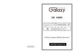
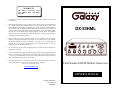
WARRANTY
This radio is covered by a two
year limited parts and labor
warranty.
•
“Limited” means that we will repair problems caused by factory defects or normal use
at no charge.
•
Before returning a radio to us for warranty service, please call our Service Department
for a Repair Authorization Number (RAN). This RAN must be written below your
return address on the outside of the shipping box. Boxes, which arrive without a RAN,
will be refused, and the shipping company will return the unopened box to you. Be sure
to have a pen and paper ready along with the serial number of your radio before calling.
We will give you the RAN and our shipping address over the phone. The telephone
number of the Service Department is (760) 480-8800, and we suggest calling between
10:00 AM and 4:00 PM Pacific Time.
•
Please include a note with a detailed description of the symptoms. This is important
because it will help the technician who works on your radio to locate your problem.
Intermittent problems are easily overlooked, so be sure to give as much detail as
possible in your note. Also, please include your telephone number in case our
technicians have any additional questions.
•
Do not send your power cord or microphone unless we ask for these items during our
telephone conversation.
•
You are responsible for getting the radio safely to us. (We suggest using United Parcel
Service.) You must pay to ship the radio to us, and we will pay to ship the radio back to
you. Since we use UPS and they do not ship to Post Offices boxes, please provide us
with a street address for the return of your radio.
•
We will repair and return your radio as soon as we can. We appreciate your choosing a
Galaxy radio and we want you to be on the air as much as possible!
Be sure to visit our web site at
DX−33HML
Full Channel AM/FM Mobile Transceiver
www.GalaxyRadios.com
OWNER’S MANUAL
Printed In Malaysia
AT3601014H
PD000802
TABLE OF CONTENTS
Specification . . . . . . . . . . . . . . . . . . . . . . . . . . . . . . . . . . . .
Page
2
Installation
Location . . . . . . . . . . . . . . . . . . . . . . . . . . . . . . . . . . . . .
4
Mounting the Connection . . . . . . . . . . . . . . . . . . . . . . .
4
Ignition Noise Interference . . . . . . . . . . . . . . . . . . . . . .
5
Antenna . . . . . . . . . . . . . . . . . . . . . . . . . . . . . . . . . . . .
5
Tuning the Antenna for Optimum SWR . . . . . . . . . . . .
6
External Speaker . . . . . . . . . . . . . . . . . . . . . . . . . . . . . .
7
Fig. 3 Microphone plug pin numbers viewed from rear of pin receptacle.
Be sure that the housing and the knurled ring of Fig. 2 are pushed back onto
the microphone cable before starting to solder. If the washer is not captive to
the pin receptacle body, make sure that it is placed on the threaded portion of
the pin receptacle body before soldering.
If the microphone jack is used to hold the pin receptacle during the soldering
operation, best results are obtained when the connections to pins 1 and 3 are
made first and then the connections to pins 2 and 4. Use a minimum amount
of solder and be careful to prevent excessive solder accumulation on pins,
which could cause a short between the pin and the microphone plug housing.
Operation
Control Functions . . . . . . . . . . . . . . . . . . . . . . . . . . . . .
8
A. Front Panel . . . . . . . . . . . . . . . . . . . . . . . . . . . . . . . .
8
B. Rear Panel . . . . . . . . . . . . . . . . . . . . . . . . . . . . . . . . .
10
Press-To-Talk Microphone . . . . . . . . . . . . . . . . . . . . . .
11
Operating Procedure to Receive . . . . . . . . . . . . . . . . . .
11
Operating Procedure to Transmit . . . . . . . . . . . . . . . . .
11
Alternate Microphones and Installation . . . . . . . . . . . .
12
-1-
1.
When all soldering connections to the pins of the microphone plug are
complete, push the knurled ring and the housing forward and screw the
housing onto the threaded portion of the pin receptacle body. Note the location
of the screw clearance hole in the plug housing with respect to the threaded
hole in the pin receptacle body. When the housing is completely threaded into
the pin receptacle body, a final fraction of a turn either clockwise or
counterclockwise may be required to align the screw hole with the threaded
hole in the pin receptacle body. When these are aligned, the retaining screw is
then screwed into the place to secure the housing to the pin receptacle body.
2.
The two cable clamp retainer screws should now be tightened to secure the
housing to the microphone cord. If the cutting directions have been carefully
followed, the cable clamp should secure to the insulating jacket of the
microphone cable.
3.
Upon completion of the microphone plug wiring, connect and secure the
microphone plug in the transceiver.
- 14 -
Specifications
GENERAL
Frequency Range
Frequency Control
Frequency Tolerance
Frequency Stability
Operating Temperature
Range
Microphone
Input Voltage
Size
Weight
Antenna Connector
Meter
Fig. 2 Microphone plug wiring
4.
Remove the retaining screw
5.
Unscrew the housing from the pin receptacle body
6.
Loosen the two cable clamp retainer screws.
7.
Feed the microphone cable through the housing, knurled ring and washer as
shown Fig. 2.
8.
The wires must now be soldered to the pins as indicated in the above wiring
tables. If a vise or clamping tool is available it should be used to hold the pin
receptacle body during the soldering operation, so that both hands are free to
perform the soldering. If a vise or clamping tool is not available, the pin
receptacle body can be held in a stationary position by inserting it into the
microphone jack of the front panel. The numbers of the pins of the microphone
plug are shown in Fig. 3, as viewed from the back of the plug. Before
soldering the wire to the pins, pre-tin the wire receptacle of each pin of the
plug.
Plug-in dynamic; with push-to-talk switch and
coiled cord.
13.8V DC nominal, 15.9V max, 11.7V min.
(Positive or negative ground).
Transmit: AM full mod., 2.2A.
Receiver: Squelched, 0.3A.
Maximum Audio output, 0.7A.
2-3/8” (H) x 7-7/8” (W) x 9-1/4” (D).
5 Ibs.
UHF, SO239
Illuminated; indicates relative output power,
received signal strength.
TRANSMITTER
Power output
- 13 -
28.065 to 28.505 MHz
Phase Lock Loop (PLL) synthesizer.
0.005%
0.001%
-30 °C to +50 °C.
Modulation
Spurious Emissions
Frequency Response
Output Impedance
Output Indicators
AM/FM, High-7 watts
Low-3.5 watts
High-and low-level Class B,
Modulation: AM. Variable
Frequency Modulation: FM.
60 dB
AM and FM: 450 to 2500 Hz.
50 ohms, unbalanced
Meter shows relative RF output
SWR. Transmit LED glows
transmitter is in operation.
-2-
Amplitude
capacitance
power and
red when
ATERNATE MICROPHONES AND INSTALLATION
RECEIVER
Sensitivity
Selectivity
Image Rejection
IF Frequency
Adjacent-Channel
Rejection
RF Gain Control
Automatic Gain Control
(AGC)
Squelch
ANL
Noise Blanker
Audio Output Power
Frequency Response
Built-in Speaker
External Speaker (Not
Supplied)
AM: 0.5 µV for 10 dB (S+N)/N at greater than
½ -watt of audio output.
FM: 1.0 µV for 20 dB (S+N)/N at greater than
½-watt of audio output.
AM/FM: 6 dB @ 3 KHz, 50 dB @ 9 KHz.
More than 65 dB.
AM/FM: 10.695 MHz 1st IF, 455 KHz 2nd IF
60 dB AM
For best results, the user should select a low-impedance dynamic type
microphone or a transistorized microphone. Transistorized type microphones have
a low output impedance characteristic. The microphones must be provided with a
four-lead cable. The audio conductor and its shielded lead comprise two of the
leads. The fourth lead is for receive control, and the third is for transmit control.
The microphone should provide the functions shown in schematic below.
4 WIRE MIC CABLE
Pin Number
Mic Cable Lead
1
Audio shield
2
Audio Lead
3
Transmit control
4
Receive Control
45 dB adjustable for optimum signal
reception.
Less than 10 dB change in audio output for
inputs from 10 to 100,000 microvolts.
Adjustable; threshold less than 0.5 µV.
Switchable
RF type
4 watts into 8 ohms.
300 to 2800 Hz.
8 ohms, round.
8 ohms; disables internal speaker when
connected.
Fig. 1 Your transceiver microphone schematic.
If the microphone to be used is provided with pre-cut leads, they must be revised as
follows.
1.
Cut leads so that they extend 7/16” beyond the plastic insulating jacket of the
microphone cable.
2.
All leads should be cut to the same length. Strip the ends of each wire 1/8” and
tin the exposed wire.
Before beginning the actual wiring read carefully, the circuit and
wiring information provided with the microphone you select. Use the
minimum head required in soldering the connections. Keep the exposed
wire lengths to a minimum to avoid shorting when the microphone plug is
reassembled.
-3-
- 12 -
PRESS-TO-TALK MICROPHONE
The receiver and transmitter are controlled by the press-to-talk switch on the
microphone. Press the switch and the transmitter is activated, release switch to
receive. When transmitting, hold the microphone two inches from the mouth and
speak clearly in a normal “voice”. The radios come complete with low-impedance
(500 ohm) dynamic microphone. For installation instruction on other microphones,
see next section, “ALTERNATE MICROPHONES AND INSTALLATION”.
OPERATING PROCEDURE TO RECEIVE
Installation
LOCATION
Plan the location of the transceiver and microphone bracket before starting the
installation. Select a location that is convenient for operation and does not interfere
with the driver or passengers in the vehicles. In automobiles, the transceiver is
usually mounted below the dash panel, with the microphone bracket beside it.
1.
Be sure that power source, microphone and antenna are connected to the
proper connectors before going to the next step.
2.
Turn unit on by tuning VOL control clockwise on your transceiver.
MOUNTING THE CONNECTION
Your transceiver is supplied with a universal mounting bracket. When
mounting the bracket and radio to your car, make sure it is mechanically strong.
Also provide a good electrical connection to the chassis of the vehicle. Proceed as
follows to mount the transceiver:
3.
Set the VOLUME for a comfortable listening level.
1.
4.
Set the MODE switch to the desire mode.
5.
Listen to the background noise from the speaker. Turn the SQUELCH control
slowly clockwise until the noise JUST disappears (no signal should be
present). Leave the control at this setting. The SQUELCH is now properly
adjusted. The receive will remain quiet until a signal is actually received. Do
not advance the control too far, or some of the weaker signals will not be
heard.
After you have determined the most convenient location in your vehicle, hold
the transceiver with mounting bracket in the exact location desired. If nothing
will interfere with mounting it in the desired position, remove the mounting
bolts. Before drilling the holes, make sure nothing will interfere with the
installation of the mounting bolts.
2.
Connect the antenna cable plug to the standard receptacle on the rear panel.
Most antennas are terminated with a type PL-259 plug and mate with the
receptacle.
3.
Connect the red DC power input wire (with the fuse) to +13.8V DC. This wire
extends from the rear panel. In automatic installation, +13.8V DC is usually
obtained from the accessory contact on the ignition switch. This prevents the
set being left on accidentally when the driver leaves the car and also permits
operating the unit without the engine running. Locate the accessory contact on
most ignition switches by tracing the power wire from the AM broadcast
receiver in the car.
4.
Connect the black lead to –13.8V DC. This is usually the chassis of the car.
Any convenient location with good electrical contact (remove paint) may be
used.
5.
Mount the microphone bracket on the right side of the transceiver or near the
transceiver, using two screws supplied. When mounting in an automobile,
place the bracket under the dash so the microphone is readily accessible.
6.
Set CHANNEL selector switch to the desired channel.
7.
Set the RF gain control fully clockwise for maximum RF gain.
OPERATING PROCEDURE TO TRANSMIT
1.
Select the desired channel of transmission.
2.
Set the MIC GAIN control fully clockwise.
3.
If the channel is clear, depress the push-to-talk switch on the microphone and
speak in a normal voice.
- 11 -
-4-
IGNITION NOISE INTERFERENCE
Use of a mobile receiver at low signal levels is normally limited by the
presence of electrical noise. The primary source of noise in automobile installations
is from the generator and ignition system in the vehicle. Under most operating
conditions, when signal level is adequate, the background noise does not present a
serious problem. Also, when extremely low level signals are being received, the
transceiver may be operated with vehicle engine turned off. The unit requires very
little current and therefore will not significantly discharge the vehicle battery.
Even though the transceiver has ANL and NB controls, in same installations
ignition interference may be high enough to make good communications
impossible. The electrical noise may come from several sources. Many possibilities
exist and variations between vehicles require different solutions to reduce the noise.
ANTENNA
A vertically polarized, quarter-wavelength whip antenna provides the most
reliable operation and greatest range. Shorter, loaded-type whip antennas are more
attractive, compact and adequate for applications where the maximum possible
distance is not required. Also, the loaded whips do not present the problems of
height imposed by a full quarter-wavelength whip.
Mobile whip antennas utilize the metal body of the vehicle as a ground
plane. When mounted at a corner of the vehicle they are slightly directional, in the
direction of the body of the vehicle. For all practical purpose, however, the
radiation pattern is nondirectional. The slight directional characteristic will be
observed only at extreme distance. A standard antenna connector (type SO239) is
provided on the transceiver for easy connection to a standard PL 259 cable
termination.
If the transceiver is not mounted on a metal surface, it is necessary to run a
separate ground wire from the unit to a good metal electrical ground in the vehicle.
When installed in a boat, the transceiver will not operate at maximum efficiency
without a ground plate, unless the vessel has a steel hull.
Before installing the transceiver in a boat, consult your dealer for information
regarding an adequate grounding system and prevention of electrolysis between
fittings in the hull and water.
-5-
REAR PANEL
17. POWER. Accepts 13.8V DC power cable with built-in fuse (4 amp.) to be
connected.
18. EXT SP. Accepts 4 to 8 ohms, 5 watt external speaker to be connected. When
external speaker is connected to this jack, the built-in speaker is automatically
disconnected.
19. PA. SP. Used to connect a PA speaker (8 ohm 4W) for PA operation. Before
operating PA you must first connect a PA speaker to this jack.
20. ANTENNA. Accepts 50 ohm coaxial cable with a type PL-259 plug to be
connected.
21. F.C. This socket is optional for the accessories FREQUENCY COUNTER
model FC-347, to indicate the value of the frequency ranges used.
- 10 -
5.
MODE (PA/FM/AM) SWITCH. This switch is used to select PA, FM, AM
mode of operation. The AM or FM mode is normally, but when you set to PA
position, the transceiver acts as a public address amplifier. Before operating
PA, you must first connect an external PA speaker (8 ohm, more than 2W) to
the PA Speaker jack on the unit rear panel.
6.
BAND SELECTOR. This switch selects A, B, C, D, E, or F band of
operation.
7.
ECHO. This control is used to echo effect.
8.
TIME. This control is used to intervals of echo sound.
9.
CHANNEL SELECTOR. This switch selects any one of the forty channels
desired. The selected channel appears on the LED readout directly above the
Channel Selector knob.
TUNNING THE ANTENNA FOR OPTIMUM SWR
Since there is such a wide variety of base and mobile antennas, this section
will strictly concern itself to the various types of mobile adjustable antennas.
Because the antenna length is directly related to the channel frequency, it
must be tuned to resonate optimally all 40 channels of the transceiver. Channel 1
requires a longer antenna than Channel 40 because it is lower in frequency.
Due to the various methods of adjusting antennas for proper SWR we have
chosen what we think is the optimum method:
A. Antennas with adjustment screws (set screws)
1. Start with the antenna extended and tightens the set screw lightly enough so
that the antenna can be lightly tapped with your finger for easy adjustment.
2.
10. METER. This meter indicates received signal strength, transmitter RF output
power.
11. RF POWER. This switch is used to select transmitting power. In the HI
position, the transceiver operates in 7 watts RF output power. In the MED
position, the transceiver operates 4 watts RF output power. In the LO position,
the transceiver operates in 1 watts RF output power.
12. OFF/ANL/NB. When the switch is placed in the ANL+NB position, the RF
Noise Blanker also is activated. The RF Noise Blanker is very effective for
repetitive impulse noise such as ignition interference.
13. BAND SWITCH-HI/LOW. This switch is used to select High band and or
Low band Frequency Range.
14. OFF-ECHO SWITCH. This switch is used to add an echo effect to your
transmitting voice, when to ECHO position.
15. RECIEVER/TRANSMIT INDICATOR. The receiver/transmit LED
indicator is located next to the channel indicator. When in receive, the LED
will be green. When in transmit the LED will be red.
16. CHANNEL INDICATOR. Numbered LED indicates the selected channel
you wish to operate on. LED indicates “9” when CH-9 is switched on.
Set your transceiver to Channel 21. @ Low band D or Hi band A. Press the
PTT (push-to-talk) switch, and tap the antenna (making it shorter). The SWR
meter will show a lower reading each time the antenna is tapped. By
continuing to shorten the antenna you will notice the SWR reading will reach a
low print and then start riding again. This means that you have passed the
optimum point for Channel 21. Extend the antenna a short distance and again
follow the procedure above.
When the lowest point has been reached, switch to Channel 1 @ Low band A
or Hi band A and then to Channel 40 @ Low band D or Hi band D and
compare SWR readings. They should be almost equal.
B. Antennas which must be cut to proper length.
1. Follow the same procedure as above, but adjust the length by cutting in 1/8”
increments until a good match is obtained.
2.
Be very careful not to cut too much at one time, as one it is cut, it can no
longer be lengthed.
3.
The whip is easily cut by filing a notch all the way around and breaking the
piece off with pliers.
NOTE
THE PROPER SETTING IS ACHIEVED WHEN THE SWR IS
1.5 OR BELOW, AND WHEN IT HAS THE SAME READING
FOR CHANNELS LOW BAND A1 AND HI BAND D40.
If you are having difficulties in adjusting your antenna, check the following:
A. All doors must be closed when adjusting the antenna.
B. Make sure the antenna base is grounded.
C. Check your coaxial cable routing (it may be pinched when routed into the
car).
-9-
-6-
D. Try a different location on your car (keeping in mind the radiation pattern
you wish)
E. Is the antenna perfectly vertical?
F. Try a different location in your neighborhood. Stay away from large
metal objects when adjusting (metal telephone or light posts, fences, etc.).
NOTE
Operation
CONTROL FUNCTIONS
There are thirteen controls and three indicators on the front panel of your
transceiver.
The transceiver will operate into an SWR of 2 to 1 indefinitely
and sustain an SWR of 20:1 for a maximum of 5 minutes at rated
operating conditions.
EXTERNAL SPEAKER
The external speaker jack (EXT.SPK) on the rear panel is used for remote
receiver monitoring. The external speaker should have 8 ohms impedance and be
able to handle at least 4 watts. When the external speaker is plugged in, the internal
speaker is disconnected.
FRONT PANEL
-7-
1.
OFF/ON/VOLUME (inner dual concentric). Turn clockwise to apply power
to the unit and to set the desired listening level. During normal operation, the
VOLUME control is used to adjust the output level obtained either at the
transceiver speaker or the external speaker, if used.
2.
SQUELCH (outer dual concentric). This control is used to cut off or
eliminate receiver background noise in the absence of an incoming signal. For
maximum receiver sensitivity it is desired that the control be adjusted only to
the point where the receiver background noise or ambient backgrounds noise is
eliminated. Turn fully counterclockwise then slowly clockwise until the
receiver noise disappears. Any signal to be received must now be slightly
stronger than the average received noise. Further clockwise rotation will
increase the threshold level, which a signal must overcome in order to be
heard. Only strong signals will be heard at a maximum clockwise setting.
3.
MIC GAIN (inner dual concentric). Adjust the microphone gain in the
transmit and PA modes. This controls the gain to the extent that full talk power
is available several inches away from the microphone.
4.
RF GAIN CONTROL (outer dual concentric). Use to reduce the gain of the
RF amplifier under strong signal conditions.
-8-