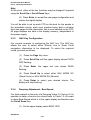
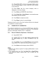
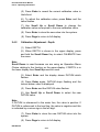
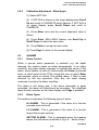
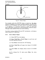
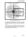
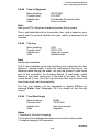
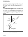
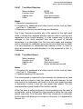
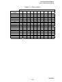
1
Hercules 2000 User Manual
Part 2 - Operating Information
2.3.1
Function Selection
Our first example will be to select another function for one of the
pages. The new function is Stored Log and since we want to place
this function in the bottom display we will be using the Scroll Down
Key.
(1) Press the SPD/DEP Key until the display is showing
BOAT SPD in the upper display and DEPTH in the lower
display.
(2) Press Scroll Down, the lower text now shows DEPTH
flashing, the upper display is not affected.
(3) Press Scroll Down until the lower text shows LOG
flashing, the upper display is not affected.
(4) Press Enter, the lower text now shows STD LOG
flashing, the upper display not affected.
(5) Press Enter again, the lower display now shows
required function, the upper display is not affected.
We are now able to view this function; press the Page Key, the
configured pages will return and Stored Log will no longer be
displayed. If you wish to keep Stored Log on a page, then you can
configure the page.
2.3.2
Page Display Configuration
The Page Key allows the user to configure four pages per FFD
depending on the required use at that position.
To store the setting in Paragraph 2.3.1 as a permanent new page,
proceed as follows:
(1) Press Scroll Up or Scroll Down and scroll text to
CNFG DSP.
Note
Scroll Up or Scroll Down can be used because we are configuring
the whole page, both upper and lower displays.
(2) Press Enter, PAGE is shown in the appropriate
display.
(3) Press Enter, the digital display is blanked and the two
functions selected are displayed in the text.
HB-084504
2-9
Hercules 2000 User Manual
Part 2 - Operating Information
Note
At this point, either of the two functions may be changed if required
using the Scroll Up or Scroll Down Keys.
(4) Press Enter to accept the new page configuration and
restore the digital display.
You will be able to set up each FFD on the boat for the people in
the immediate vicinity, each crew member being able to develop
their own pages for the information that is most needed on the FFD.
All page displays are held in the display memory, independent of
the power supply.
2.3.3
NAV Key Configuration
Our second example is configuring the NAV key. The NAV key
allows the user to select either Rhumb Line or Great Circle
navigation information to be displayed. To select the required
mode, proceed as follows:
(1) Press the Page Key once.
(2) Press Scroll Up until the upper display shows CNFG
DSP flashing.
(3) Press Enter, the upper text now shows PAGE
flashing.
(4) Press Scroll Up to select either NAV MODE GC
(Great Circle) or NAV MODE RH (Rhumb).
(5) Press Enter to select your desired choice. The
display will stop flashing.
2.3.4
Damping Adjustment - Boat Speed
Our third example is the entry of a Damping Value. To find out if it is
possible to damp a function you should refer to Table 1.2. We want
to damp Boat Speed which is in the upper display we therefore use
the Scroll Down Key.
(1) On the upper display select BOAT SPD.
HB-0845-04
2-10
Hercules 2000 User Manual
Part 2 - Operating Information
(2) When BOAT SPD is shown in the upper display, press
and hold Scroll Down to select DAMPING which flashes
in the lower text.
(3) Press Enter and the current damping value is
displayed on the lower display.
(4) Press Enter and DAMPING value flashes.
(5) Press Scroll Up or Scroll Down to increase/decrease
the damping value as required.
(6) Press Enter to accept new value.
(7) Press Page to return to normal display.
Damping control for any of the other functions that can be damped
is completed in a similar manner.
2.4
EXAMPLES OF CALIBRATION
The method of calibration for your Hercules 2000 System should be
made clear by following the examples of calibration. The calibration
process is described in detail in Part 3 - Calibration.
2.4.1
Manual Calibration Adjustment - Boat Speed
(1) Select BOAT SPD.
(2) If BOAT SPD is in the upper display, press and hold
the Scroll Down Key to select CALIBRATE from the
menu.
(3) Press Enter then press Scroll Down and the display
shows MANL CAL, which is the choice that we require.
(4) Press Enter and the display shows SINGLE.
Notes
1. SINGLE is the choice required if a single paddle-wheel or sonic
speed is fitted.
2. If two paddle-wheels are fitted, the Scroll Up or Scroll Down
Keys should be used to select PORT CAL or STBD CAL, as
required.
HB-084504
2-11
Hercules 2000 User Manual
Part 2 - Operating Information
(5) Press Enter to reveal the current calibration value in
Hertz/knot.
(6) To adjust the calibration value, press Enter and the
value flashes.
(7) Use Scroll Up or Scroll Down to change the
calibration value as required to the new calibration value.
(8) Press Enter to store the new value into the system.
(9) Press Page to return to full display.
2.4.2
Calibration Adjustment - Depth
(1) Select DEPTH.
(2) When DEPTH is shown in the upper display, press
and hold the Scroll Down Key to select CALBRATE from
the menu.
Note
Scroll Down is used because we are using an Operation Menu
Choice relating to the function on the upper display. If DEPTH is in
the lower display then Scroll Up must be used.
(3) Select Enter and the display shows DATUM which
flashes.
(4) Press Enter again, DATUM stops flashing and the
current datum value is displayed.
(5) Press Enter and the DATUM value flashes.
(6) Use Scroll Up or Scroll Down to select the new
DATUM value.
Note
If DATUM is referenced to the water line, the value is positive. If
DATUM is referenced to the keel line, the value is negative and this
is indicated by a minus sign in the left digit.
(7) Press Enter to store the new DATUM value into the
system.
(8) Press Page to return to full display.
HB-0845-04
2-12
Hercules 2000 User Manual
Part 2 - Operating Information
2.4.3
Calibration Adjustment - Wind Angle
(1) Select APP W/A.
(2) If APP W/A is shown on the lower display press Scroll
Up and scroll to CALBRATE which flashes. If APP W/A is
on upper display, press Scroll Down and scroll to
CALBRATE.
(3) Press Enter twice and the current alignment value is
shown.
(4) Press Enter, MHU ANGL flashes, use Scroll Up or
Scroll Down to select the new value.
(5) Press Enter to accept the new value.
(6) Press Page to return to the normal display.
2.5
ALARMS
2.5.1
Alarm Control
When a pre-set alarm parameter is reached, e.g. the depth
reducing, the system raises an alarm automatically. In an alarm
condition, the lower display changes to highlight the cause of the
alarm, which flashes on and off continuously until Enter is pressed
twice; at which point all the FFDs except the one on which Enter
was pressed, return to normal. The audible alarm, if fitted, is also
silenced by this key operation. After this, the lower display
continues to monitor the alarm condition.
The alarm is still active and, if the alarm parameter is again
exceeded, the alarm will flash/sound as necessary. The displayed
alarm function remains on the lower display until Page is pressed.
2.5.2
Alarm Types
The system incorporates the following types of alarm:
HI ALARM - This is generated if the value of a function
exceeds a pre-set level.
LO ALARM - This is generated if the value of a function
drops below a pre-set level.
SECTOR ALARM - This is generated when the heading
leaves the safe sector as shown in Fig 2.2. - Sector Alarm.
HB-084504
2-13
Hercules 2000 User Manual
Part 2 - Operating Information
Example
Heading
Safe Sector
-20° +20°
Alarm Sector
Fig 2.2 - Sector Alarm
For example, when the SECTOR alarm is turned on, the alarm
reference heading is the current compass heading. If the SECTOR
alarm is set at 40 degrees, the sector value is the compass heading
+/- 20 degrees. It is therefore important to switch the SECTOR
alarm OFF before carrying out a course alteration, switch the alarm
ON again when settled on the new course heading.
Any alarm can be switched ON and OFF individually, or all alarms
can be turned OFF collectively.
2.5.3
Set Lo Alarm - Depth
(1) Select DEPTH on the display.
(2) Press Scroll Up or Scroll Down to scroll text until
ALARMS appears flashing.
(3) Press Enter, text shows ALL OFF flashing.
(4) Press Scroll Up until upper text shows LO ALARM
flashing.
(5) Press Enter, the display shows current LO ALARM
value.
(6) To change the LO value press Enter, the value
flashes.
HB-0845-04
2-14
Hercules 2000 User Manual
Part 2 - Operating Information
True Wind Angle
Port Tack
0˚
0˚
20˚
True Wind Angle
Starboard Tack
10˚
0˚
10˚
10
20˚
30
˚
3
˚
4
80˚
80˚
Target Boat
Speed Upwind
70˚
70˚
˚
60
60
˚
˚
50
Optimum True Wind
Angle Upwind
50
6
40
˚
8
4
90˚ 100˚
110
˚
˚ 90˚
˚ 100
2
Target Boat
Speed Downwind
14
Optimum True Wind
Angle Downwind
0˚
13
1
0˚
2
0
˚1
3
5
7
Maximum VMG
Downwind
1
10
˚ 1
0
2
3
Maximum VMG
Upwind
˚ 180˚ 170˚
16
˚ 170
0
˚
160
15
0˚
0˚
15
1
40
0˚
˚
9 Kts
Boat Speed
Fig 2.4 - Polar Performance Curve
The advantage of tacking performance over VMG is that it takes
into account changes in windspeed. You should also be aware of
the potential inaccuracies caused by your polar table being
incorrect.
Tacking Performance has a CALBRATE option which allows you to
choose a type of polar table which equates to your type of yacht. In
the next Paragraph, Target Boat Speed, we discuss polar tables in
general and the implications of this choice.
HB-084504
2-37
Hercules 2000 User Manual
Part 2 - Operating Information
2.9.40
Target Boat Speed
Menu heading:
Function text:
Update rate:
Units:
PERFORM
TARG SPD
Once per second
Knots
Note
At optimum wind angle.
This is the boat speed at which the optimum VMG will be achieved,
and can be measured from the polar table or obtained by careful
analysis of both VMG and boat speed while you are sailing.
The polar table describes the performance of the boat in all
conditions of true wind speed and angle. The boat speed is plotted
radially against the true wind angle for each true wind speed in turn.
The result is a diagram as shown in Fig 2.4 - Polar Wind Curve,
which shows the boat speed plotted for just one value of true wind
speed.
Polar tables can be derived either by theoretical predictions, the
IMS certificate for instance, or by analysing the boat's actual
performance. You may well use one of these techniques to obtain
your polar table, however, if you do not, then the Hercules 2000 has
one polar table already stored in its memory. A copy of this polar
table is shown in Table 2.1 on page 2-47.
The polar table is located within the Hercules 2000 system under
the following:
PERFORM → TACKING, CALBRATE → CAL VAL1 (TAB TYPE)
It can then be scaled to your rating using the RATING Menu choice,
which is at the same level, and found by:
PERFORM → TACKING, CALBRATE → CAL VAL2 (RATING)
These values are entered in the normal manner.
Once you have understood and developed the polar table it will
improve all the performance functions: reaching and tacking
performance, optimum wind angle and target boat speed, as well as
the predictions of next leg.
HB-0845-04
2-38
Hercules 2000 User Manual
Part 2 - Operating Information
We can see from Fig. 2.4 how the target boat speed is obtained
from the polar tables. It is the point at which a perpendicular drawn
to the 0 degree true wind angle first touches the curve, hence
optimising speed in a windward direction. The boat speed on the
curve at this point becomes the target boat speed for that wind
speed, and the true wind angle at that point becomes the optimum
wind angle. The two combined give the optimum VMG and so allow
us to calculate tacking performance.
2.9.41
Tidal Set and Drift
Menu heading:
Function text:
Update rate:
Units:
NAVIGATE
TIDE SET or TIDE RTE
Once per second
Degrees magnetic, knots
Notes
1. Damping 0-99 minutes.
2. Calibration: Magnetic variation.
3. Some position fixers output the current local magnetic variation
on the NMEA 0183 port using either HVD, HVM, RMA or RMC
sentences. As a result, CAL VAL1 on the TIDE SET function will
be automatically set to the correct variation.
Your position fixer will either supply true or magnetic bearing to the
Hercules 2000. If it supplies true bearing then you must enter the
magnetic variation into the Hercules 2000. It is found in the menu
under:
NAVIGATE → TIDE SET, CALBRATE → CAL VAL 1 (MAG VAR)
Note
If your position fixer sends magnetic bearing, check that the
variation is correctly entered.
The calculation involves comparing the course and speed over the
ground, from the position fixing system, to the course and speed of
the boat through the water, from the dead reckoning. Any
differences are due to the tidal set and drift, and can be displayed
as such. To make this accurate the dead reckoning requires the
leeway input which in turn, requires the clinometer to measure heel
angle.
HB-084504
2-39
Hercules 2000 User Manual
Part 2 - Operating Information
The damping on this function is adjustable and can be important. In
rapidly changing tidal situations you need to lower the damping
down as far as possible to be able to see the changes quickly.
Conversely, in a steady tide or current the longer the period over
which the calculation is averaged, the more accurate the results will
be.
The lag in the position fixer's ability to adjust to rapid changes in
direction, such as tacks, should also be borne in mind when
considering the results of this function. Frequent tacking produces
figures which are unreliable and should be treated with caution.
2.9.42
Timer
Menu heading:
Function text:
Update rate:
Units:
TIME
TIMER
Once per second
Hours, Minutes, Seconds
Note
Individually resettable.
Used for both the start and to record elapsed time during a
handicap race. The timer will act as either a stopwatch or a
countdown from 5, 10 or 15 minutes.
The Enter Key will toggle the display between minutes/seconds and
hours/minutes. Paragraph 2.6.1 describes control of the timer.
2.9.43
Time to Layline
Menu heading:
Function text:
Update rate:
Units:
TIME
TIME L/L
Provide by the position fixer
Hours, minutes, seconds
Note
Requires NMEA 0183 interfaced position fixing system transmitting
the ZDL sentence.
This function is linked to Layline Distance. The information
displayed shows the time to go before reaching the appropriate
layline. A value of zero indicates time to tack or gybe.
HB-0845-04
2-40
Hercules 2000 User Manual
Part 2 - Operating Information
2.9.44
Time to Waypoint
Menu heading:
Function text:
Update rate:
Units:
WAYPOINT
ETA WPT
Provided by the position fixer
Hours, minutes
Note
Also gives ETA. Requires interfaced position fixing system.
This is calculated directly by the position fixer, and is based on your
speed over the ground towards the mark, which is assumed to be
constant.
2.9.45
Trip Log
Menu heading:
Function text:
Update rate:
Units:
LOG
TRIP LOG
Once per second
Nautical miles
Note
Individually resettable.
This is the resettable log for trip recording and reads from the time
started in nautical miles. It must be remembered that this is the
distance sailed through the water, not over the ground. It also forms
part of the calculation for Average Speed. A particularly useful
feature is that when reset prior to the start of the race, the Timer
counts down to zero, the Trip Log (and any other trip functions that
have been reset) start automatically.
The Trip Log display can be expanded to display 9999nm by
pressing Enter. See Paragraph 2.6.2 for details of trip function
control.
2.9.46
True Wind Angle
Menu heading:
Function text:
Update rate:
Units:
WIND
TRUE W/A
Once per second
Degrees
Notes
1. Relative to the boat’s heading.
2. Corrected for masthead and other errors via the look-up table.
3. Variable damping 0-99 seconds.
HB-084504
2-41
Hercules 2000 User Manual
Part 2 - Operating Information
The true wind is calculated from the vector triangle shown in Fig.
2.5. This uses the apparent wind speed, apparent wind angle and
the boat speed in the calculation. The results are then corrected by
the true wind correction tables, which are discussed in Part 3 Calibration.
Note
The true wind is the wind relative to the water, not the land. The true
wind is not the same as the ground wind, unless there is zero tide.
The true wind angle is the angle between the boat's heading and
the true wind. It is probably used downwind more often than upwind,
when it is easier to steer to a wind angle than to a boat speed. In
addition, the Tactician will find it very useful for gybing angles
downwind.
N
True Wind
Speed
True Wind
Direction
True Wind
Angle
Apparent
Wind Speed
VMG
Boat
Speed
Heading
Measured Apparent
Wind Angle
Fig 2.5 - True Wind Angle
HB-0845-04
2-42
Hercules 2000 User Manual
Part 2 - Operating Information
2.9.47
True Wind Direction
Menu heading:
Function text:
Update rate:
Units:
WIND
TRUE DIR
Once per second
Degrees magnetic
Notes
1. Magnetic compass point
2. Corrected for Masthead and other errors via the look-up table,
see Part 3 - Calibration.
3. Damping control via true wind angle and heading.
This is the Tactician's greatest ally in the search for the right wind
shifts. It shows the compass direction that the wind is coming from
regardless of the boat's heading. It is the easiest way to pick up
changes in the wind direction that can be used to tactical
advantage. It is calculated from the true wind angle and heading,
and is corrected for calibration errors by the true wind look-up table.
It is very important to understand the function of this, in order to
have an accurate true wind direction. It is fully explained in Part 3 Calibration.
2.9.48
True Wind Speed
Menu heading:
Function text:
Update rate:
Units:
WIND
TRUE W/S
Once per second
Knots, metres per second
Notes
1. Corrected for masthead and other errors via the look-up table,
see Part 3 - Calibration.
2. Variable damping 0-99 seconds.
True wind speed is required by the trimmers for decisions on sails
choice and as a check of sail trim when the wind changes. As the
wind varies the helmsman will need to let the boat speed increase
or decrease to bring it onto the new target boat speed. The true
wind provides a good check of the intuitive results.
When the boat is sailing downwind, the air passing over the mast is
accelerated, and in the past this has tended to make the true wind
speed over-read. The Hercules 2000 has introduced a calibration
for this which will allow you to correct out the error, it is explained in
Section 3.6
HB-084504
2-43
Hercules 2000 User Manual
Part 2 - Operating Information
2.9.49
VMG to Waypoint
Menu heading:
Function text:
Update rate:
Units:
WAYPOINT
VMG WPT
Provided by the position fixer
Knots
This is another function which is directly calculated by the position
fixing system. This can be a very important function on free legs,
particularly if you are a long way from the mark, since the greatest
VMG to Waypoint is not necessarily obtained by sailing straight at
the mark. In Fig 2.6 we can see how this works.
True Wind
Direction
Direction of
Next Mark
Direction for
Maximum VMG
to Next Mark
Polar Curve
Fig 2.6 - Optimum VMG to a Mark
HB-0845-04
2-44
Hercules 2000 User Manual
Part 2 - Operating Information
2.9.50
VMG
Menu heading:
Function text:
Update rate:
Units:
SPEED
VMG
Once per second
Knots
Note
Upwind/downwind.
As a measure of performance VMG has both advantages and
disadvantages. It is calculated from the true wind angle and the
boat speed.
VMG
BOAT SPD
KT
KT
True Wind
Direction
VMG
KT
BOAT SPD
KT
True Wind
Direction
True Wind
Angle = 150
Boat Speed
5.8 Knots
VMG
4.44
Knots
VMG
5.54
Knots
Boat Speed
6.4 Knots
True Wind
Angle = 40
Up Wind
Down Wind
Fig 2.7 - Calculation of VMG
VMG can measure the performance upwind and downwind much
more effectively than boat speed, since it takes into account how
close the boat is sailing to the wind. However, it is not possible for
the helmsman to sail to it directly because of the momentum of the
HB-084504
2-45
Hercules 2000 User Manual
Part 2 - Operating Information
boat. As the boat sails closer to the wind, the VMG will initially rise
because the boat will hold its speed due to the energy contained in
its momentum. VMG increases, and the helmsman, seeing this,
would be encouraged to sail even closer to the wind thus increasing
the VMG still further. Ultimately the boat will be head to wind and
stop dead. VMG will then drop.
Because of this, the technique has been developed of analysing the
boat’s performance to find out at which speed the greatest VMG
occurs.
Once this is known the helmsman steers to this target boat speed
knowing that this is optimising their upwind or downwind
performance.
Whilst VMG is an important part of sailing technique, it should be
checked by someone other than the helmsman. This person should
develop a feel for the boat speeds when the greatest VMG is
attained and then communicate these to the helmsman.
2.9.51
Wind Angle to the Mast
Menu heading:
Function text:
Update rate:
Units:
PERFORM
W/A MAST
Once per second
degrees
Note
Requires mast rotation sensor
When the mast rotation sensor is fitted, this measures the apparent
wind angle to the mast's centreline, thus giving the actual attack
angle of the entry of the sail to the wind.
HB-0845-04
2-46
Hercules 2000 User Manual
Part 2 - Operating Information
Table 2.1 - Polar Table 0
TRUE WIND
ANGLE
20
30
40
50
60
70
80
90
100
110
120
130
140
150
160
170
180
OPTIMUM VMG
OPT TWA U/W
OPTIMUM VMG
OPT TWA D/W
2.5
5.0
7.5
1.56
1.87
2.08
2.13
2.19
2.10
2.02
2.00
1.98
1.99
1.97
1.90
1.87
1.84
1.80
1.75
1.70
1.80
40
1.80
157
2.70
3.04
3.29
3.52
3.75
3.83
3.91
3.90
3.85
3.76
3.65
3.50
3.25
3.01
2.80
2.60
2.40
2.85
39
2.70
158
3.57
4.04
4.40
4.67
4.95
5.22
5.40
5.45
5.40
5.26
5.08
4.90
4.60
4.20
3.90
3.65
3.42
3.79
38
3.70
160
TRUE WIND SPEED IN KNOTS
10.0 12.5
15
17.5
20
4.10
4.88
5.49
5.90
6.09
6.18
6.27
6.31
6.39
6.39
6.30
6.00
5.67
5.23
4.80
4.50
4.30
4.34
37
4.80
161
4.50
5.30
5.99
6.50
6.69
6.79
6.88
7.02
7.10
7.11
7.06
6.87
6.67
6.30
5.80
5.50
5.29
4.69
36
5.70
162
4.80
5.66
6.54
6.95
7.07
7.22
7.30
7.45
7.59
7.65
7.65
7.51
7.38
7.04
6.60
6.31
6.02
5.00
35
6.20
163
5.00
5.95
6.78
7.23
7.36
7.48
7.61
7.74
7.87
7.96
8.00
7.96
7.80
7.56
7.20
6.96
6.83
5.23
34.5
6.80
165
5.20
5.99
6.87
7.33
7.45
7.58
7.73
7.88
8.03
8.19
8.30
8.21
8.10
7.93
7.70
7.53
7.44
5.33
34
7.40
168
22.5
25
5.50
6.15
6.86
7.35
7.51
7.67
7.89
8.11
8.30
8.40
8.43
8.36
8.28
8.19
8.05
7.93
7.88
5.37
34
7.80
170
5.40
6.20
6.75
7.29
7.50
7.72
7.95
8.18
8.39
8.50
8.53
8.48
8.42
8.37
8.27
8.22
8.17
5.32
33.5
8.10
172
HB-084504
2-47