1
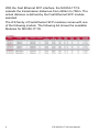
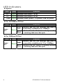
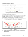
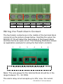
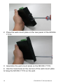
IFS MC250-1T/1S User Manual P/N 1072573 • REV R00.03 • ISS 10SEP12 Copyright Trademarks and patents Manufacturer Version Certification FCC compliance ACMA compliance European Union directives © 2012 UTC Fire & Security Company. All rights reserved. Interlogix, IFS MC250-1T/1S, the IFS Brand and logo are trademarks of UTC Fire & Security. Other trade names used in this document may be trademarks or registered trademarks of the manufacturers or vendors of the respective products. UTC Fire & Security Americas Corporation, Inc. 2955 Red Hill Avenue, Costa Mesa, CA 92626-5923, USA This document applies to IFS MC250-1T/1S version 1.0. N4131 Class A: This equipment has been tested and found to comply with the limits for a Class A digital device, pursuant to part 15 of the FCC Rules. These limits are designed to provide reasonable protection against harmful interference when the equipment is operated in a commercial environment. This equipment generates, uses, and can radiate radio frequency energy and, if not installed and used in accordance with the instruction manual, may cause harmful interference to radio communications. Operation of this equipment in a residential area is likely to cause harmful interference in which case the user will be required to correct the interference at his own expense. Notice! This is a Class A product. In a domestic environment this product may cause radio interference in which case the user may be required to take adequate measures. 2004/108/EC (EMC directive): Hereby, UTC Fire & Security declares that this device is in compliance with the essential requirements and other relevant provisions of Directive 2004/108/EC 2002/96/EC (WEEE directive): Products marked with this symbol cannot be disposed of as unsorted municipal waste in the European Union. For proper recycling, return this product to your local supplier upon the purchase of equivalent new equipment, or dispose of it at designated collection points. For more information see: www.recyclethis.info. Contact information Customer support www.utcfireandsecurity.com or www.interlogix.com www.interlogix.com/customer-support Contents Overview 1 Package Contents 1 Product Features 2 Installation 3 Product Description 3 Front Panel 5 LED Indicators 6 Converter Top Panel 7 Wiring the Power Inputs 7 Wiring the Fault Alarm Contact 8 Mounting Installation 9 Installation Steps 13 Switch Operation 14 Troubleshooting 16 Specifications 17 RJ45 Pin Assignments 18 Contacting Technical Support 20 IFS MC250-1T/1S User Manual i Overview This section describes the functionalities of the IFS MC2501T/1S Industrial Media Converter’s components and guides how to install it on the desktop. Basic knowledge of networking is assumed. Please read this chapter completely before continuing. In the following section, the term “Industrial Media Converter” means the IFS MC250-1T/1S. Package Contents Check the contents of your package for the following parts: • Industrial Media Converter x1 • User’s Manual x1 • DIN Rail Kit x 1 • Wall Mount Kit x 1 If any of these items are missing or damaged, please contact your distributor or IFS sales rep immediately. If possible, retain the original carton and packaging material in case of need to return the product for repair/replacement. IFS MC250-1T/1S User Manual 1 Product Features Physical Port MC250-1T/1S 1-Port 10/100Base-TX RJ-45 1-Port 100Base-FX SFP slot (Distance depends on SFP module) Industrial Design Slim type IP-30 metal case -40 to +75 Degree C operating temperature DIN rail and wall mount design 12 to 48V DC, redundant power with polarity reverse protection and detachable terminal block connectors for master and slave power Supports EFT protection 6000V DC for power line Supports 6000V DC Ethernet ESD protection Data Communication Complies with the IEEE 802.3, IEEE 802.3u Fast Ethernet standard Auto-MDI/MDI-X detection and Auto-negotiation with Half-Duplex / Full-Duplex modes for 10 /100Base-TX RJ-45 port Store-and-Forward switching architecture Features Store-and-Forward mode with wire-speed filtering and forwarding rates Prevents packet loss with back pressure (Half-Duplex) and IEEE 802.3x PAUSE frame flow control (FullDuplex) Support to handle up to 1522bytes packet size CSMA/CD protocol Automatic source address learning and aging 2 IFS MC250-1T/1S User Manual Installation This section describes the functionalities of the Industrial Fast Ethernet Switch’s components and guides how to install it on the desktop. Basic knowledge of networking is assumed. Please read this chapter completely before continuing. In the following section, the term “Industrial Fast Ethernet Switch” means the MC250-1T/1S. Product Description The MC250-1T/1S is an industrially hardened media converter which is specially designed to operate from -40 to 75℃ temperature. The MC250-1T/1S provides highly reliable and stable operations for demanding of environments. The MC250-1T/1S provides a high level of immunity to electromagnetic interference and heavy electrical surges typical of environments found on plant floors or in curb side traffic control cabinets. The feature of operating temperature range of -40 to 75 Degrees C coupled with hazardous location certification allows the media converter to be placed in almost any location. The MC250-1T/1S is packaged in a compact, IP-30 standard metal enclosure that allows either DIN or panel mounting for efficient use of cabinet space. The media converter provides an integrated power supply with a wide range of voltages (12 to 48V DC) for worldwide operability or dual-redundant, reversible polarity, 24V DC and 48V DC power supply inputs for high availability applications requiring dual or backup power inputs. The MC250-1T/1S provides 1 x 10/100Base-TX and 1 x 100Base-FX optic-fiber SFP interface. IFS MC250-1T/1S User Manual 3 With the Fast Ethernet SFP interface, the MC250-1T/1S extends the transmission distances from 220km to 70Km. The actual distance is defined by the Fast Ethernet SFP module selected. The IFS family of Fast Ethernet SFP modules comes with one of the following models. The following list shows the available Modules for MC250-1T/1S. 4 IFS MC250-1T/1S User Manual Front Panel The figure below shows the Front Panel of the MC250-1T/1S. IFS MC250-1T/1S User Manual 5 LED Indicators System LED Color Function P1 Green Indicates that power 1 is on. P2 Green Indicates that power 2 is on. Fault Green Indicates either power 1 or power 2 has no power. Per 10/100Base-TX Port LED Link / ACT Color Function Light Indicates that the link through that port is successfully established at 100Mbps. Blink Indicates that the Switch is actively sending or receiving data over that port. Green Per 100Base-FX Port LED Link / ACT 6 Color Function Light Indicates that the link through that port is successfully established at 10 or 100Mbps. Blink Indicates that the Switch is actively sending or receiving data over that port. Green IFS MC250-1T/1S User Manual Converter Top Panel The top panel of the MC250-1T/1S consists of a terminal block connector with two DC power inputs. Wiring the Power Inputs The 6-contact terminal block connector on the top panel of the MC250-1T/1S is used for two DC redundant powers inputs. Please follow the steps below to insert the power wires. 1. Insert positive / negative DC power wires into the contacts 1 and 2 for POWER 1, or 5 and 6 for POWER 2. V1- V1+ V2- V2+ 2. Tighten the wire-clamp screws to prevent the wires from disconnecting. IFS MC250-1T/1S User Manual 7 1 - 2 Power 1 3 4 5 Fault 6 Power 2 + - + Wiring the Fault Alarm Contact The fault alarm contacts are in the middle of the terminal block connector as the picture shows below. Inserting the wires, the MC250-1T/1S will detect the fault status of the power failure and then forms an open circuit. The following illustration shows an application example for wiring the fault alarm contacts. 1 2 3 4 5 6 Insert the wires into the fault alarm contacts Note: The wire gauge for the terminal block should be in the range between 12 ~ 24 AWG. The alarm relay circuit accepts up to 30V, max. 3A current. 8 IFS MC250-1T/1S User Manual Mounting Installation This section describes how to mount the MC250-1T/1S and make connections to it. Please read the following section and perform the procedures in the order presented. Note: In the installation steps below, this Manual uses the IFS 8 Port Industrial Gigabit Switch, GE-DSGH-8, as an example. However, the steps for any IFS Industrial Switch & Industrial Media Converter are similar. Mounting to a DIN-Rail The DIN-Rail kit comes assembled on the MC250-1T/1S out of the box. Please refer to following figures to install the device on a DIN-Rail. IFS MC250-1T/1S User Manual 9 1. Lightly press down and push the bottom of the DIN-Rail connector mount into the track. 2. Check that the DIN-Rail connector mount is tightly mounted on the track. 3. Please refer to following procedures to remove the MC2501T/1S from the track. 10 IFS MC250-1T/1S User Manual 4. Lightly press down and pull the bottom of DIN-Rail connector mount to remove it from the track. Mounting to a Wall To install the MC250-1T/1S on the wall, please follow the instructions described below. 1. Loosen the screws to remove the DIN Rail from the Media Converter. IFS MC250-1T/1S User Manual 11 2. Place the wall mount plate on the rear panel of the MC2501T/1S. 3. Assemble the wall mount plate on the MC250-1T/1S 4. Use the hook holes at the corners of the wall mount plate to hang the MC250-1T/1S on the wall. 12 IFS MC250-1T/1S User Manual Installation Steps Step 1: Unpack the Industrial Fast Ethernet Switch. Step 2: Check that DIN-Rail is screwed on the Industrial Fast Ethernet Switch. (Please refer to the DIN-Rail Mounting section for DIN-Rail installation. If you want to wall mount the Industrial Fast Ethernet Switch, then please refer to Wall Mount Plate Mounting section for wall mount plate installation. Step 3: To install the Industrial Fast Ethernet Switch on the DIN-Rail track or wall, please refer to the Mounting Installation section. Step 4: Power on the Industrial Fast Ethernet Switch. (Please refer to the Wiring the Power Inputs section for power input) The power LED on the Industrial Fast Ethernet Switch will light up. Please refer to the LED Indicators section for meaning of LED lights. Step 5: Prepare the twisted-pair, straight through Category 5 cable for Ethernet connection. Step 6: Insert one side of Category 5 cables into the Industrial Fast Ethernet Switch Ethernet port (RJ-45 port) and the other side to the network device Ethernet port (RJ-45 port), ex: Switch, PC or Server. The UTP port (RJ-45) LED on the Industrial Fast Ethernet Switch will light up when the cable is connected to the network device. Please refer to the LED Indicators section for LED light meaning. Step 7: Insert fiber cable from the MC250-1T/1S to the fiber network. TX, RX must be paired at both ends. The optical port LED on the MC251-1T/1S will illuminate when the connection is established with network device. Please refer to the LED Indicators section for LED light meaning. Step 8: When all connections are set up and the LEDs illuminate, the installation is completed. IFS MC250-1T/1S User Manual 13 Switch Operation Address Table The Industrial Fast Ethernet Switch is implemented with an address table. This address table is composed of many entries. Each entry is used to store the address information of each node in the network, including MAC address, Port No., etc. This information comes from the learning process of the Industrial Fast Ethernet Switch. Learning When one packet comes from any port of the Industrial Fast Ethernet switch, the Industrial Fast Ethernet Switch will record the source address, port no. and other related information in the address table. This information will be used to decide either forwarding or filtering for future packets. Forwarding & Filtering When one packet comes from another port of the Industrial Fast Ethernet Switch, it will also check the destination address besides the source address learning. The Industrial Fast Ethernet Switch will lookup the address-table for the destination address. If not found, this packet will be forwarded to all the other ports except the port which this packet came in. And these ports will transmit this packet to the network it's connected to. If found, and the destination address is located at a different port from this packet comes in, the Industrial Fast Ethernet Switch will forward this packet to the port where this destination address is located according to the information from address table. But, if the destination address is located at the same port with this packet comes in, then this packet will be filtered. Store-and-Forward Store-and-Forward is one type of packet-forwarding techniques. A Store-and-Forward Industrial Switch stores the incoming frames in an internal buffer and checks for any errors 14 IFS MC250-1T/1S User Manual from the frames before transmission. Lack of error packet occurrence is important for an efficient and stable network.. The Industrial Fast Ethernet Switch scans the destination address from the packet-header, searches the routing table provided for the incoming port and forwards the packet, only if required. The fast forwarding makes the switch attractive for connecting servers directly to the network, thereby increasing throughput and availability. However, the switch is most commonly used to segment existing hubs, which nearly always improves overall performance. Ethernet Switching can be easily configured in any Ethernet network environment to significantly boost bandwidth using conventional cabling and adapters. Due to the learning function of the Industrial Fast Ethernet Switch, the source address and corresponding port number of each incoming and outgoing packet are stored in a routing table. This information is subsequently used to filter packets whose destination address is on the same segment as the source address. This confines network traffic to its respective domain, reducing the overall load on the network. The Industrial Fast Ethernet Switch performs "Store-andForward" therefore, no error packets occur. More reliably, it reduces the re-transmission rate. No packet loss will occur. Auto-negotiation The TP ports on the Industrial Fast Ethernet Switch have builtin “Auto-negotiation”. This technology automatically sets the best possible bandwidth when a connection is established with another network device (usually at Power On or Reset). This is done by detecting the modes and speeds at the moment both devices are connected. IFS MC250-1T/1S User Manual 15 Troubleshooting This chapter contains information to help resolving issues. If the Industrial Fast Ethernet Switch is not functioning properly, make sure the device was set up according to instructions in this manual. The Link LED is not light Solution: Check the cable connection of the Industrial Fast Ethernet Switch. Performance is bad Solution: Check the speed duplex mode of the partner device. The Industrial Fast Ethernet Switch is operating at Auto-negotiation mode by default and if the partner is set to half duplex, then the performance will become bad. Link LED is illuminated but the traffic is irregular Solution: Check that the attached device is not set to dedicate full duplex. Some devices use a physical or software switch to change duplex modes. Auto-negotiation may not recognize this type of full-duplex setting. Why does the Industrial Fast Ethernet Switch not connect to the network? Solution: Check every port LED on the Industrial Fast Ethernet Switch. Try another port on the Industrial Fast Ethernet Switch to make sure the cable is installed properly while making sure the cable is the right type Turn off the power and turn on the power again after waiting for awhile. 16 IFS MC250-1T/1S User Manual Specifications Product MC250-1T/1S Hardware Specification 10/100Base-TX Port 100Base-FX Port 1 RJ-45 Auto-MDI/MDI-X port 1 SFP Slot Fiber Port Type Cable Distance Optical Frequency Launch Power (dBm) Receive Sensitivity (dBm) Maximum Input Power (dBm) Dimension (W x D x H) Deprends by SFP module 135mm x 85mm x 32mm 430g Weight Installation DIN rail kit and wall mount ear Maximum Frame Size 1522bytes packet size Flow Control Back pressure for half duplex, IEEE 802.3x Pause Frame for full duplex Enclosure IP-30 Slim Type Metal Case System: • Power 1 (Green), • Power 2 (Green), • Fault (Green) 1x copper port: • 10/100 (Green) • LNK/ACT(Green) LED Indicator 1 x 100FX port: • 100 (Green) • LNK/ACT(Green) Power Input 12 to 48V DC Redundant power with polarity reverse protection function Power Consumption 3 Watts/ 10BTU (maximum) IFS MC250-1T/1S User Manual 17 When connecting to other Ethernet equipment such as a Router, Bridge, Switch, or Hub, please refer to that device’s Technical Manual. RJ45 Pin Assignments 10/100Mbps, 10/100Base-TX RJ-45 Connector pin assignment Contact MDI Media Dependant Interface MDI-X Media Dependant Interface -Cross 1 Tx + (transmit) Rx + (receive) 2 Tx - (transmit) Rx - (receive) 3 Rx + (receive) Tx + (transmit) 4, 5 6 Not used Rx - (receive) 7, 8 Tx - (transmit) Not used RJ45 Cable Drawing The following figure shows the pin allocation and color of a straight cable, and connection of a crossover cable. 18 IFS MC250-1T/1S User Manual Please make sure your connected cables are with same pin assignment and color as above picture before deploying the cables into your network. IFS MC250-1T/1S User Manual 19 Contacting Technical Support Contact technical support if you encounter any difficulties during this installation. Please make sure you have the requested diagnostic or log files ready before you contact us by phone or go to www.interlogix.com/customer-support. Technical Support Europe, Middle East and Africa W Select Contact Us at www.utcfssecurityproducts.eu North America T +1 855.286.8889 E [email protected] Australia E 20 [email protected] IFS MC250-1T/1S User Manual