1
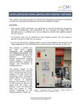
Nikon C1si Spectral Laser Scanning Confocal Microscope User Guide Contents: C1Si Turn-On/ShutDown Procedures ............................................................................................. 2 Overview ......................................................................................................................................... 4 Setup for epi-illumination to view through the eyepieces: ............................................................... 5 Setup for confocal imaging:............................................................................................................. 5 Notes:.............................................................................................................................................. 6 Troubleshooting .............................................................................................................................. 7 Owners Consortium: Department of Pathology SABRE Proctor Foundation Page 1 of 7 C1Si Turn-On/ShutDown Procedures Turn On: 1. Turn on arc lamp (Nikon Intensilight on shelf above table). This should be left on for at least 30 minutes at a run and turned off for at least 30 minutes prior to turning on again, this prevents the arc from flickering and wearing out prematurely 2. Turn on the lasers that you will use: (you don’t need to turn them all on) a. 2x Diodes on the laser bench: turn key from 12 o’clock to 3 o’clock. b. 1x Diode on top of the control box: turn key and then push ‘laser on’ (green button). c. Argon-Ion multi-line: Turn the key clockwise (do not turn off switch). 3. Turn on the remote focus accessory: switch is on left hand side of box. 4. Turn on the control box (Nikon D-Eclipse C1). Don’t start software until ‘ready’ light is on. 5. Make sure the Z-stepper motor slider (located back-right of microscope) is pushed down for manual operation (or up if you are going to use the remote focus accessory). 6. Choose and carefully load 1 or 2 objective lenses. Center the lever so that both lens sockets are in the up position. Use both hands and gently thread it until it is finger tight. Do not over tighten it or it will get stuck. Available Objectives Number 1 2 3 4 5 6 Objective 10x/0.30 NA W Plan Fluor 20x/0.75 NA air CFI Plan Apo 40x NIR/ 0.8 NA W 40x/1.30 NA oil Plan Fluor 60x/1.2 NA W NIR Apo 60x/1.4 NA oil Plan Apo VC Theoretical Resolution (nm) 1017 Depth of field (um) Transmitted light Working Distance Comments 14.4 Suggested step size (um) 5.76 DIC N1/10x 0.3 mm 407 2.31 0.924 DIC N2/20x 0.75 mm Water Dipping Air 381 2.03 0.812 3.5 mm 235 0.77 0.308 DIC N2/40x III DIC N2/40x II 250 ~0.7 ~0.4 DIC N2/60x I 0.27 mm 218 0.66 0.264 DIC N2/60x I 0.21 mm 0.20 mm Water Dipping Oil Immersion Water Immersion Oil Immersion Dipping objectives are designed to form an image without a cover slip, whereas immersion lenses require a cover slip. For ideal imaging, always use #1.5 cover slips. You can then switch between the two different objectives that you have loaded by turning the lever on the front so that it is in the middle (this is very important because if it is not in the middle the objectives can come crashing down and get damaged), pressing the black button on the top right, and carefully moving the carriage forward or backwards. Page 2 of 7 7. Turn on computer: 8. Launch software (EZ-C1 3.80). a. Choose the colors you are going to use: 408/488/561, 488/561/638, or 457/514 (If you plan on doing spectral imaging it doesn’t matter what you choose in the software). 9. Choose standard or spectral detector. a. Standard detector: Flip lever on side of the scanhead diagonal. b. Spectral detector: Flip lever on side of scanhead vertical. 10. Choose excitation/emission wavelengths and put in scanhead dichroics and filter cubes: Scanhead Dichroic Left Filter Cube Right Filter Cube Beam splitter (spectral detector) BS 20/80 n/a n/a Blue/Green/Red 408/488/561 595/50 450/40 525/50 Green/Red/Far Red 488/561/638 685/70 525/50 595/50 CFP/YFP 457/514 550/50 485/30 11. Align pinhole for your particular scanhead dichroic that you have selected: a. Place a green fluorescent slide under your objective and focus on it using the arc lamp and the eyepieces (you need to push the eyepiece slider in, open the shutter, and choose the GFP filter cube) – it gets very bright so you can put in the neutral density filters on the back right of the scope so you don’t blind yourself. b. Engage the confocal (pull eyepiece slider out, close shutter, and move filter cube to open position – #6). c. Turn the software onto live and set it up so the color changes with intensity, 256x256 pixels, green laser and green detector are on, and then go live. d. Turn up the gain on the green detector until you get signal. e. Use a 2.5mm hex key to align the pinhole using the two screws on the bottom right of the scan head. i. This is done by ‘walking’ the pinhole: Move one screw until it gets as bright as possible, then move the other screw to the brightest point, return to the first one, and repeat until you get the brightest image possible. If the image gets too bright so that all the pixels are saturated just turn down the detector gain. 12. Take off the fluorescent slide and start imaging! 13. If using transmitted light, turn on halogen lamp (Lamp with dial on shelf) or turn off for fluorescence. Page 3 of 7 14. As needed, engage the Z-stepper-motor (used to do Z-stacks) by pulling up gently (on back right of microscope). Shutdown: 1. If no one is signed up 2 hours after your session is over: a. Raise objectives fully up and move up the focus. b. Clean off oil objectives with lens paper and replace lens in its holder. c. Reverse of Turn on, items 61. 2. If someone is signed up after you: a. Turn off EZ-C1 software. b. Leave everything else on. Overview The C1si is a confocal laser-scanning microscope with four lasers for multi-color imaging. It has 4 lasers with these laser lines: 408nm, 457nm, 488nm, 514nm, 561nm, 638nm. It has 2 types of detectors: one with 3 standard band pass detectors and one with a spectral detector that can image 32 different channels at the same time (they can be set to be 2.5nm, 5nm, and 10nm wide). It is on an upright Nikon FN1 microscope with a large electrophysiology stage. The max penetration depth into tissue is approximately 100–200 µm depending on the opacity of the sample. To move the objective turret between the two lens positions, center the lever so that both lenses are in the up position and then press the button on the upper right part of the carriage and move forward or back. Make sure that it is in the very center so that when you change positions it does not fall down and get damaged. Note: the viewed area may change because of slight differences in lens position between the two holders. Page 4 of 7 Setup for epi-illumination to view through the eyepieces: 1. Choose dichroic for appropriate fluorophore. 2. Open shutter at epi source and shutter on front of scope (move to ‘O’ from ‘C’). 3. Turn off brightfield. 4. View sample through the eyepieces. Filters for the Eyes Fluorophore Cube D/F/R 1. D/F/R DAPI 2. UV2E/C Ex 340-380 Em 435-485 CFP GFP Rhodamine Confocal 3. CyGFP 4. B2EC Ex 465-495 Em 515-555 5. G2E/C 6. Empty Setup for confocal imaging: 1. Choose position ‘6’ on the filter wheel. 2. Close the shutter on the front of the scope (move to ‘C’). 3. Turn off brightfield. 4. Choose the Objective that you are using in the top right box (this is very important so that you get the correct scaling!). 5. Turn on and off the detectors and lasers that you want to use (remember that they are on when the background is colored, and they are off when the background is black) a. If you are using ‘frame lambda’ set up each pass individually b. Set your pinhole: generally it is best to leave it at a small (30 micron) pinhole unless there is a compelling reason to change it 6. If using the standard detector set the detector gains at 6.5 (your usable range is generally between 5 and 8) 7. Go live and slowly turn up the laser power to your sample and then increase/decrease detector gain as needed. Typical laser powers: <20% for 408nm, <30% for 488nm, <50% for 561nm. a. It is important not to over saturate your image, you can check this by making saturated pixels colored i. Go to Color and click the check box ‘add saturation indicator’. b. Do this for each frame lambda pass c. When finished setting up your passes uncheck the ‘preview pass’ checkbox to allow you to take all passes at the same time 8. Average: a. Use this to decrease noise in your sample without increasing laser power. b. In order to use this you need to press on the green check box on the top window 9. Z-stack: a. Clear everything by pressing the red bars. Page 5 of 7 b. Set a reference point (any point in between your top and bottom) c. Set the top by either engaging the stepper motor and focusing up or entering in a number. d. Set the bottom same as the top. e. Set step size (the N button sets Nyquist-Shannon Sampling which is 2.7 times the theoretical resolution limit) f. Now click the green check box in the top window so when you click single it takes the whole z-stack (if you do this beforehand it will take a z-stack while you are trying to set the z-stack up) i. Always make sure that the stepper motor is engaged! 10. Zoom: a. Click on the top right box with the cube in it b. Use this corners of the box to zoom in and grab the middle to move it around c. To zoom out drag the field zoom bar in the XY window all the way to the right d. Check the XY tab to see what your pizel size is and whether you are doing Nyquist-Shannon Sampling (2.7 times the resolution limit). You know you have reached this because the note ‘not optimum pixel size’ disappears. 11. XY basic: a. Pixel dwell time: this is how long the laser stays on one pixel. I usually leave this at the minimum time. b. Field zoom: the zooming that you have done in step 10. c. Pixels: I recommend using either 512x512 or 1024x1024 but you can do arbitrary if you want 12. Time: a. Use this to set up your time-series: interval and number of acquisitions. Notes: 1. Saving Files: a. Always save them as .ids (this will save 2 files: a .ids and .ics and both of them are needed to open it at a later date) 2. Spectral Un-mixing: (only for when using the spectral detector) a. Draw a ROI on image on each single color that you want to unmix (just red or just green – it can be useful to have samples that are only stained with one color for this) b. Menu: SpectralUnmixfollow script. 3. 3 Dimensional Rendering: a. DataVolumeVolume Render 4. 3D Orthogonal Rendering: (my favorite way to image a z-stack in EZ-C1) a. Go to view and then in the drop down menu select 3D Orthogonal i. This allows you to image XY, XZ, and YZ at the same time Page 6 of 7 Troubleshooting • The z stepper motor is not working The Make sure that the knob is pulled up on the rear left of the microscope. • If you cannot see anything in the eyes (epi) follow this checklist: The arclamp (Intensilight) is turned on. The shutter above the nosepiece is open. Number 1-5 is selected on the filter wheel. The eyepiece/scanhead changer is pushed in. You are focused on your sample. The aperture on the Intensilight source is at position 1 (maximal transmitted light). • If you cannot see anything on the computer (confocal), follow this checklist: You are focused on your sample. The filter wheel is set to 6. The eyepiece/scanhead changer is pulled out. Both the detector and laser are turned on so they are colored. The detectors that you want are moved to 6.5 or higher. The sliders for the Lasers that you want are on. • Your sample is getting photo-bleached too quickly: Try using less laser power and more detector gain. Try focusing using single frames instead of live. • Your image is too noisy: Try increasing laser power and decreasing detector gain. • Optimizing to get higher resolution: Use a higher NA objective. Zoom in by clicking on the cube in the top right corner of the screen. It will tell you when this has been reached when the NON OPTIMAL PIXEL SIZE disappears. This happens when you get Nyquist sampling of (0.61*emission wavelength)/Numerical Aperture so that you have 2.7 pixels per diffraction limit. Page 7 of 7