1
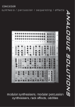
VOSTOK
user
user manual
manual
ANALOGUE SOLUTIONS (c) 2-2009
vostok v2 e&oe
1
Contents
Specification .................................................................................................3
Safety Instructions ........................................................................................6
The Case ......................................................................................................7
MIDI-CV Converter .....................................................................................14
Voltage Controlled Oscillators 2 & 3 (VCO 2 & 3) ......................................17
Voltage Controlled Oscillator 1 (VCO1) ......................................................19
VC LFOs 1 & 2 ...........................................................................................22
Envelope Generators 1 & 2 ........................................................................23
S+H / NOISE ..............................................................................................25
8 Step CV and Gate Sequencer .................................................................26
Joystick Controller ......................................................................................28
VC Multimode Filter / VCA- [ HPF / LPF / VCA] .........................................30
Ring Mod ....................................................................................................33
6 Input Audio / CV / Gate Mixer with Inverter .............................................34
Split (Multiple) .............................................................................................36
Adaptor / External .......................................................................................36
ANALOGUE SOLUTIONS (c) 2-2009
vostok v2 e&oe
2
Specification
234256
Matrix patch combinations
484
Matrix patch panel points
75
Sockets
52
Rotary controls
13
LEDs
21
Switches
1
Displays
Size:
Dimensions shown do not include feet/handles/catches.
Complete closed case: 274 (H) x 440 (W) x 188 (D)
Lid internal depth: 50mm (enough to leave in most types of patch lead).
Main Case internal depth: 134mm
Weight:
Power
110/230V AC input - switchable.
Matrix Patch Panel
Matrix pin patch panel with a 22x22 connection size. The matrix panel gives the patching
versatility of a modular without the need for confusing & front-panel interfering patch cables. It’s
the neatest & most versatile method of creating patches.
External Patching
Matrix panels alone do not allow interfacing with external synthesisers & signals, so the Vostok
also provides a full complement of front panel jack socket patch points for additional internal &
external patching & interfacing.
The Vostok may at first glance look like an EMS clone, but it is not, and not intended to be.
It may share the matrix panel and suitcase style design, but that’s where the similarities end. The
Vostok has far more features packing a powerful amount of modular synthesiser power into one
small suitcase.
ANALOGUE SOLUTIONS (c) 2-2009
vostok v2 e&oe
3
Full Spec’..All ciruits are totally analogue with the exception of the MIDI interface.
Control Modules
MIDI to CV Converter
CV1 (pitch) / CV2 (controller) / Gate / Accent / Legato, MIDI Thru, channel select, manual trigger
Joystick
2 way joystick controller
Sequencer
8 step CV & Gate analogue sequencer, range switch, manual step
Audio Modules
VCO1
Saw / Square / Triangle waves, Octave switch, Glide, Sync
VCO2
Saw / Square / 3 Sub waves, Pulse Width, Glide, Sync
VCO3
Saw / Square / 3 Sub waves, Pulse Width, Glide, Sync
Noise
White noise source
Voltage Controlled Multimode Filter
2 Filters based on Korg MS20 circuitry.
Independent Cut Off and Resonance for Low Pass Filters and High Pass Filters.
The VCLPF and VCHPF combine to produce a 3rd filter type, Band Pass
Voltage Controlled Amplifier
VCA With 1/4” jack audio output.
Ring Modulator
AC ring mod
CV Modules
EG 1
ADSR envelope generator, Normal/Inverse output, Repeat function
EG 2
ADSR envelope generator, Normal/Inverse output, Repeat function
VCLFO1
Ramp, Reverse Ramp, Square,Triangle waves, Voltage controlled frequency
VCLFO2
Ramp, Reverse Ramp, Square,Triangle waves, Voltage controlled frequency
Sample and Hold
S+H with Slew
Utility Modules
Mixer
CV / Audio Mixer. 6 input with Normal and Inverse output
Signal Meter
The meter input is taken from the Mixer output. It is back-lit.
Split 1 and 2
2 multiples, each is 4 way
Adaptor
ANALOGUE SOLUTIONS (c) 2-2009
vostok v2 e&oe
4
6.35mm / 3.5mm jack socket converters
External (Adaptor 2)
6.35mm / 3.5mm jack socket converter wired into the matrix board
Power
Internal filtered mains transformer, IEC lead connection, double fused, 115/230VAC switchable.
Matrix Patch Panel
Utilises a patch panel with 22x22 connections. The patching versatility of a modular without the need for confusing & front-panel interfering patch cables. Pins supplied are 10K
resistance type.
Lead Patching
Jack socket patch points provided for additional internal & external patching & interfacing.
LEDs
13 of them!
Case
Portable suitcase with chrome catches, carry handle & lift off front panel.
ANALOGUE SOLUTIONS (c) 2-2009
vostok v2 e&oe
5
Safety Instructions
Please read carefully before using:
• Only use the recommended power - 230V (Europe) 110V (USA) AC
• Never handle the power adaptor with wet hands
• Never excessivly bend the adaptor cable, or get it trapped or place heavy objects on it. If
the adaptor cable becomes damaged, replace the adaptor.
• Ensure the unit is disconnected from the mains before moving or cleaning.
• Always disconnect the unit from the mains if there is lightning in your area.
• Ensure the unit is on a stable surface, and never place heavy objects on top of it.
• Never allow young children to operate the unit or power adaptor.
• Do not use excessive force when using the controls or inserting cables to the connectors.
• The unit should not be operated in the rain or near water and should not be exposed to
moisture. If the unit is brought from a cold environment to a warm one, the unit should be left to
reach the ambient temperature. This is to allow any possible condensation moisture inside the
unit to evapourate. Although any built up moisture will not damage the unit, any shorting may be
hazardous.
• Never open the case or attempt to make repairs. Refer any servicing to a qualified service
personnel.
• Do not eat.
• Do not use the unit in a manor that is likely to cause offence.
ANALOGUE SOLUTIONS (c) 2-2009
vostok v2 e&oe
6
The Case
The Vostok case has been designed to be compact and portable. It is made from strong steel,
steel hinges, chrome plated steel latcehs. Plus sprung effect steel handle. However, the case does
not have ‘full flight case’ strength. If you wish to transport the unit via courier, freight and other
delivery services, like all other delicate musical instruments, it must be packed well, ideally in a
foam lined full flight case.
Power
The Vostok requires 230V AC (Europe) or 110V AC (USA). Ensure the voltage selection switch
is correctly set before connecting a power cable.
The IEC inlet is double fused and filtered.
Always turn the power switch off and disconnect the mains lead when the Vostok is not in
use.
Top Cover
The cover is attached via 2 hinges and 2 catches. To remove the cover, release the catches.
Open up the cover far enough so it can be lifted off the hinges.
When closing the cover, ensure it is correctly lined up with the main case before shutting
catches. If you are leaving patch cables in the synth, ensure the moulded plugs are not too long
to fit the cover. Also ensure no cables are caught in the sides when shutting.
Using
The Vostok can be laid flat (horizontally) or upright (vertically). It has rubber feet on both
surfaces.
ANALOGUE SOLUTIONS (c) 2-2009
vostok v2 e&oe
7
patching
ANALOGUE SOLUTIONS (c) 2-2009
vostok v2 e&oe
8
Patching
The Vostok uses patch pins to make connections in the patch panel. To make a connection
between two modules, a pin must be inserted in the pin hole lining up with module source / destination.
All the signal and voltage inputs to modules are arranged in columns, lettered A to V. The
signal and voltage outputs from modules are arranged in rows numbered 1 to 22.
In the single patch example below, the pin shows where and how to connect the LFO1 sawtooth output into the VCO1 Pitch CV input. This patch point is at co-ordinates F15.
The following page lists all the patch points available and describes their function. It is not
practical to supply a patch panel that provides every possible signal routing. All the major ones
have been included. The are a number of extra patch points that are only available via front panel
jack sockets. Also, all the pin patch points are duplicated with front panel jack sockets.
Grouping
The routing points have been grouped into audio frequency ‘SIGnals’ (e.g. oscillator outputs,
mixer inputs, filter inputs) and ‘CONTROL’ (e.g. pitch control, joystick, LFO signals). Generally
speaking you would only patch Signals to Signals and Controls to Controls. However there are
some exceptions. For example, the mixer, although designated a Signal mixer, can mix control
voltages instead (but not at the same time), the filter cut-off control inputs can be modulated with
audio frequencies.
Patch Pins
The Vostok comes with 10 resistor and 10 shorting patch pins.
Shorting
This directly links the source to the modulation, literally direct shorting.
Resistance
This has in built 10K ohm resistance. Generally speaking use the resistance pin as this allows
better mixing between source signals to destinations compared to shorting.
Shorting pins can be used when you run out of resistor pins, and are adequate for most
patches. Why don't we provide all resistor pins? Because thery are 10 times more expensive, and
that would have to be reflected in the price. Additional pices can be purchased.
ANALOGUE SOLUTIONS (c) 2-2009
vostok v2 e&oe
9
Patch Pins (continued)
Shorting
These have a short handle and are available in many colours.
Resistance
This has a long handle and incorporates a 10K resistor.
LED
These are not entirley practical but look cool! They will flash with the signal, e.g. LFO or EG.
Only use these for cool light shows. They will not work with all patches, they will attenuate the
signal slightly and they will not light if the signal is too low. You can tell an LED pin as the end is
slightly domed. These are available separately and none are provided as standard.
Caution! Insert pins carefully. Push in and pull out in a straight line.
Do not bend! They are fragile! We will not refund for bent pins.
Panel Buffering
All of the signal and control outputs are buffered, and most, but not all, of the inputs are buffered. This means when used with the resistance pins, there should be little or no signal change
when inserting more than 1 pin in any row or column.
Please note, we will choose which colours to send with the unit depending on what colours
we have in stock at that time.
ANALOGUE SOLUTIONS (c) 2-2009
vostok v2 e&oe
10
Columns : Inputs
Audio Frequency Signal Inputs
A
B
C
D
E
RM X
RM Y
FILTER
VCA
MIXER
Ring mod audio
Ring mod audio
Filter audio
VCA audio
Mixer audio (can mix CVs too)
Control Voltage Signal Inputs
F
G
H
I
J
K
L
M
N
O
P
Q
R
S
T
U
V
VCO1 PITCH
VCO2 PITCH
VCO3 PITCH
VCO2 PW
VCO3 PW
HPF CUTOFF
LPF CUTOFF
SQ CLOCK
SQ RESET
LFO1 FREQ
LFO2 FREQ
EG1 TRIG
EG2 TRIG
S+H SIG
S+H CLOCK
VCA LEVEL
EXTERNAL
Pitch CV control
Pitch CV control
Pitch CV control
Pulse width CV
Pulse width CV
Cut-off frequency CV
Cut-off frequency CV
Sequencer clock
Sequencer reset to 1
Frequency CV control
Frequency CV control
Trigger
Trigger
Sample and Hold CV signal in
Sample and Hold clock
VCA level CV
Goes to/from the EXTERNAL jacks
Rows: Outputs
Audio Frequency Signal Outputs
1
2
3
4
5
6
7
VCO1 SAW
VCO2 Square
VCO3 Square
FILTER
VCA
NOISE
MIXER
Sawtooth wave
Square wave
Square wave
Filter audio
VCA audio
White noise
Positive signal mixer out
Control Voltage Signal Outputs
8
9
10
11
12
13
14
15
16
17
18
19
20
21
22
MIDI-CV1
MIDI-CV2
MIDI-GATE
SQ CV
SQ GATE
STICK X
STICK Y
LFO1 SAW
LFO1 TRI/SQ
LFO2 SAW
LFO2 TRI/SQ
EG1
EG2
S+H
EXTERNAL
MIDI Note to CV (pitch)
MIDI controller/velocity to CV
MIDI Note on/off to Gate
Sequencer CV
Sequncer Gate
Joystick left/right
Joystick up/down
LFO1 saw/reverse saw
LFO1 triangle/square
LFO2 saw/reverse saw
LFO2 triangle/square
Envelope 1
Envelope 2
S+H output
Goes to/from the EXTERNAL jacks
ANALOGUE SOLUTIONS (c) 2-2009
vostok v2 e&oe
11
TEMPLATES FOR YOUR USE - PLEASE PHOTOCOPY
ANALOGUE SOLUTIONS (c) 2-2009
vostok v2 e&oe
12
midi
ANALOGUE SOLUTIONS (c) 2-2009
vostok v2 e&oe
13
MIDI-CV Converter
Inputs:
MIDI In
Outputs:
CV 1 (pitch)
CV 2 (control)
Gate
Legato
Accent
MIDI Thru
Indicators:
Gate LED
Controls:
MIDI program push button
Manual trigger push button
Overview
The MIDI to CV Converter (MCV) is a quick and easy to use module that allows control of
other Vostok modules from a MIDI controller.
Use
Connecting
Connect the MIDI sequencer or other MIDI device to the MIDI input of the MCV.
Normally CV1 goes to the pitch CV of a VCO. CV2 goes to any other control input, such as
filter cut-off. Gate goes to the Trigger input of an envelope or the clock in of the sequencer.
Make sure the MCV is on the right MIDI receive channel and away you go!
Details
LED
The gate activity light will be lit whenever there is a gate voltage present (i.e. whenever a
MIDI Note is on).
CV1
The pitch CV out (CV1) conforms to 1V per Octave.
CV2
The controller CV out (CV2) responds to MIDI controller 1 (mod wheel) or MIDI velocity depending how it is set-up. The range is 0 to 10V range.
Gate
When a MIDI note is on, a 10V gate signal is sent to the Gate socket.
Legato
When 1 or more notes are overlapped, this output will change from 0 to 5V. It will return to
0V when no notes are overlapping. This output is ideal for triggering other modules inputs, such
as sequencer reset or clock, VCF cut-off etc.
Accent
When a MIDI velocity of over 79 is received, the Accent output will go from 0 to 5V. It will not
return back to 0V until it receives a MIDI note velocity value of less than 80. This output is ideal for
accenting notes by connecting it to the VCA or filter cut-off input. It could also clock a sequencer
or other module.
ANALOGUE SOLUTIONS (c) 2-2009
vostok v2 e&oe
14
Note, it does not respond to pitch bend.
TRIG Button
This is a manual trigger button, sending a gate signal to the Gate socket. It can be used to
manually trigger whatever the MIDI-CV Gate socket is patched to.
MIDI Channel Selection and CV2 Control Source Assignment:
Press and hold the Program Button.
Then, either;
Press a MIDI key. CV2 will be set to Velocity, or
move the Modulation Wheel. CV2 will be set to Mod' Wheel.
Release the button.
The MIDI receive channel will be set to that of the MIDI message received mentioned
above.
ANALOGUE SOLUTIONS (c) 2-2009
vostok v2 e&oe
15
OSCILLATORS
ANALOGUE SOLUTIONS (c) 2-2009
vostok v2 e&oe
16
Voltage Controlled Oscillators 2 & 3 (VCO 2 & 3)
Inputs:
VCO CV
VCO PW
VCO Sync
Outputs:
Saw
Square
Sub1
Sub2
Sub3
Controls:
Tune
Glide
Pulse Width
Saw Level
Square Level
Overview
The VCO is usually the first in the signal chain for creating a synth patch. It provides the raw
unprocessed audio waveform for subsequent filtering and processing.
Each VCO provides two waveforms; sawtooth and square wave. The square wave’s pulse
width can be manually or CV modulated for a chorusing effect which beefs up the sound.
All VCOs also have a glide / slew generator for creating portamento effects. They also feature
Sync inputs.
Controls In Detail
Tune
Turning Tune alters the pitch of the oscillator.
Range: approx +/1 1 Octave
Glide
Turning up Glide adds portamento to the oscillator, so the pitch will bend (slide) up or down
to each note (as opposed to a sudden change). The higher the setting, the longer the oscillator
takes to reach its new note. Not many VCO modules give you the all important Glide control as
standard!
Range: 0 to 10 seconds
Pulse Width
You can alter the pulse width (duty cycle) of the square wave. Turning this gives a sound
similar to chorusing. In the centre position a square wave is produced.
Sawtooth Level
This sets the output volume of the sawtooth waveform output.
Range: 0 to 10V
Square Level
This sets the output volume of the square waveform output.
Range: 0 to 10V
Sockets in Detail
CV in
This socket is the pitch CV control input and is used to control the pitch of the oscillator.
Range: 0 to 10V
PW
This is a pulse width control CV input. CV modulation of this socket will alter the pulse width
ANALOGUE SOLUTIONS (c) 2-2009
vostok v2 e&oe
17
of the oscillator square wave.
Range: -10 to 10V
Sync In
This is an oscillator Sync reset input. Feed the Sawtooth waveform of another oscillator (at
full level) into here.
Sawtooth Out
This is the audio output for the sawtooth waveform. Its level is affected by the sawtooth level
pot.
Range: 0 to 10V
Square Out
This is the audio output for the square waveform. Its level is affected by the square level
pot.
Range: 0 to 10V
Sub 1, 2, 3 Out
These are sub-oscillators taken off the square wave, each one is one, two then three octaves
lower. Note when PWM is applied to the square wave, this may affect the Sub oscillators.
Oscillator Sync
The familiar and favourite oscillator sync sound is achieved by using two oscillators. One is
the master oscillator and each time it begins a new wave cycle, it will reset the slave oscillator. Full
details of the ins and outs of osc sync can be found various web resources.
To get this feature working on the VCO
• patch a master VCO’s sawtooth (set it at full level) waveform out into a slave VCO’s Sync
In
• Take your audio out from the slave VCO (this is where your sync sound will be)
• To control theSync effect, alter the pitch of the master VCO
Note; it is important to balance the relative pitches of the 2 oscillators to get an effective sound.
With certain settings you may not get an effect or even any audio!
ANALOGUE SOLUTIONS (c) 2-2009
vostok v2 e&oe
18
Voltage Controlled Oscillator 1 (VCO1)
Inputs:
Pitch CV
Sync
Outputs:
Triangle
Sawtooth
Square
Switches:
Octave (built into Tune control)
Controls:
Tune
Glide
Triangle Level
Saw Level
Sqaure Level
Wave CV Level
Volume
Overview
The VCO is usually the first in the signal chain for creating a synth patch. It provides the raw
unprocessed audio waveform for subsequent filtering and processing.
VCO1 provides three waveforms; triangle, sawtooth and square wave.
All VCOs also have a glide / slew generator for creating portamento effects. They also feature
Sync inputs.
Controls In Detail
Tune
Turning Tune alters the pitch of the oscillator.
Range: approx +/1 1 Octave
Octave
The Tune control has a built in octave switch. Pull the control out to lower the VCO octave
by 1.
Glide
Turning up Glide adds portamento to the oscillator, so the pitch will bend (slide) up or down
to each note (as opposed to a sudden change). The higher the setting, the longer the oscillator
takes to reach its new note.
Range: 0 to 10 seconds
Triangle Level
This sets the output volume of the triangle waveform output.
Range: 0 to 10V
Sawtooth Level
This sets the output volume of the sawtooth waveform output.
Range: 0 to 10V
Square Level
This sets the output volume of the square waveform output.
Range: 0 to 10V
ANALOGUE SOLUTIONS (c) 2-2009
vostok v2 e&oe
19
Sockets in Detail
CV in
This socket is the pitch CV control input and is used to control the pitch of the oscillator.
Range: 0 to 10V
Sync In
This is an oscillator Sync reset input. Feed the Sawtooth waveform of another oscillator (at
full level) into here.
Triangle Out
This is the audio output for the triangle waveform. Its level is affected by the sawtooth level
pot.
Range: 0 to 10V
Sawtooth Out
This is the audio output for the sawtooth waveform. Its level is affected by the sawtooth level
pot.
Range: 0 to 10V
Square Out
This is the audio output for the square waveform. Its level is affected by the square level
pot.
Range: 0 to 10V
Oscillator Sync
The familiar and favourite oscillator sync sound is achieved by using two oscillators. One is
the master oscillator and each time it begins a new wave cycle, it will reset the slave oscillator. Full
details of the ins and outs of osc sync can be found various web resources.
To get this feature working on the VCO
• patch a master VCO’s sawtooth (set it at full level) waveform out into a slave VCO’s Sync
In
• Take your audio out from the slave VCO (this is where your sync sound will be)
• To control theSync effect, alter the pitch of the master VCO
Note; it is important to balance the relative pitches of the 2 oscillators to get an effective sound.
With certain settings you may not get an effect or even any audio!
Note; on all VCOs, with no CV patched into the VCO pitch, the pitch may gradually rise. In
this case you must clamp the VCO pitch CV by patching some sort of CV to the Pitch to lock it to
some particular value.
ANALOGUE SOLUTIONS (c) 2-2009
vostok v2 e&oe
20
MODULATION
ANALOGUE SOLUTIONS (c) 2-2009
vostok v2 e&oe
21
VC LFOs 1 & 2
Inputs:
Freq CV
Outputs:
Ramp/Rev.Ramp
Tri/Square
LFO Controls:
Ramp/Rev.Ramp Level/Select
Tri/Square Level/Select
Indicators:
LFO Speed
Overview
The LFO module has 4 waveforms available on 2 outputs. Use the LFO to control another module, such as a VCO (to create vibrato), a VCA (for tremelo) or to control a filter's cut-off frequencer
(wah-wah / filter sweep). Use it any where you want to change a module's character over time.
Controls In Detail
Speed
This sets the LFO frequency / speed.
Ramp / Reverse Ramp Level / Select Switch
Sets the output level to the Ramp (sawtooth) out jack of the Ramp signal. This control has a
built in push/pull switch. Pull the control out to select Reverse Ramp.
Triangle / Square Level / Select Switch
Sets the output level to the Triangle out jack of the Triangle signal. This control has a built in
push/pull switch. Pull the control out to select Square.
Sockets In Detail
Ramp / Reverse Ramp
Outputs the Ramp or Rev.Ramp signal depending which is selected.
Range: 0 to 10V
Triangle / Square
Outputs the Triangle or Square signal depending which is selected.
Range: 0 to 10V
Frequency CV In
This is a control voltage input. The level of the input voltage controls the speed of the LFO.
This is good for creating even more interesting LFO effects. Feed the output of the envelope into
here for an LFO speed that changes over time. Or try using the CV sequencer to change the
speed on each step.
Range: 0 to 10V
ANALOGUE SOLUTIONS (c) 2-2009
vostok v2 e&oe
22
Envelope Generators 1 & 2
Inputs:
Trig In
Outputs:
EG
Indicators:
Trig LEDs
Controls:
Attack
Decay
Sustain
Release
Level
Envelope Generators (EGs) in general
The EG produces a CV that varies over a period of time. It’s start is triggered by a Gate or
Trigger signal.
The main use for an EG is to vary the volume of a sound, (when used to control a VCA), to
reproduce the way natural instruments sound. E.g. a piano sound starting loud when the key is
struck, then gradually dieing away. It can also be used to change the timbre of a sound over time,
by controlling the cut-off frequency of a VCF.
The attack time adjusts the rate at which the envelope will rise to its peak value. This is initiated with a Gate signal. The Decay adjusts the rate the signal takes to fall to the Sustain level.
The Sustain level adjusts the level that the EG signal will sustain from the end of the Decay time
till the end of the Gate signal (i.e. when the key is release). The Release time adjusts the rate the
signal takes to fall from its current level to zero, after the end of the Gate signal (when the key
was released). If a short Trigger signal is used to initiate the EG, there will be no Decay or Sustain
portion to the EG signal. The signal will rise to peak level (Attack), then imidiately fall from peak
to zero at the Release rate.
Controls In Detail
Attack
After receiving a Gate signal, this sets the time is takes the envelope to reach full level.
Decay
After reaching full level, this sets the time it takes the envelope to decrease to the Sustain
level.
Sustain
The sets the Sustain level. The envelope signal will remain at the Sustain level (after decreasing
from the maximum level) as long as there is a Gate signal present at the Trigger in socket (i.e. as
long as a key is held down).
Release
After the key is released (the Gate signal no longer present), this sets the time it takes for the
envelope signal to decrease to zero.
ANALOGUE SOLUTIONS (c) 2-2009
vostok v2 e&oe
23
Level
At centre position there is no EG output. As you turn more clockwise, the signal gets higher,
as it is turned anti-clockwise the signal is inverted and gets higher, but a a negative inverted voltage.
Sockets In Detail
Trigger In
A positive gate or trigger voltage in here will activate the ADSR sequencer.
EG Out
The envelope signal from this socket. The Level pot affects the output.
Special Repeat Function
The EGs have repeat functions which are easy to use and add a powerful modulation capabilitiy. To activate the repeat function, pull the Level control out.
The speed is set by the Attack and Decay time. (The Release control will have no effect). By
setting very short times an audio signal will be present!
Whether the repeat is short giving high frequencies (audio signals) or slow (like an LFO), by
varying the Attack or Decay times you are changing the wave shape of the output. Anything from
Saw to Triangle to Reverse Saw wave froms can be created.
ANALOGUE SOLUTIONS (c) 2-2009
vostok v2 e&oe
24
S+H / NOISE
Inputs:
S+H Clock
S+H Signal
Outputs:
S+H Sig
Noise
Controls:
S+H Slew
Noise Level
Overview
The S+H has two inputs and one output. One input is for the voltage that is to be sampled and
the other is for the clock trigger. What happens in a S+H is that when it detects a voltage signal
at its sampling input, it holds it for the duration of the clock pulse. It doesn’t matter if the sampled
voltage fluctuates at all during one clock pulse’s cycle - the output will remain constant until a
new clock pulse is received, whereupon the output will change in accordance with the sampled
voltage. This way stepped voltage changes can be created from smoothly changing inputs (from
EGs or LFOs).
When used with a noise source, random changes can be created.
Obtaining a stepped random signal (using the Sample and Hold Facility)
To create a stepped random voltage:
Patch a square wave LFO output into the S+H Clock input, the Noise output to the S+H Signal
input. Turn the Noise level up. The S+H output signal will appear at the S+H Out socket.
Controls In Detail
S+H Slew
This adds slew (or portamento) between each changing voltage held by the S+H. So as each
voltage is sampled, the changes in old to new voltage level will be smoothed out.
Noise Level
Alters the noise level.
Sockets In Detail
S+H In
This is the signal source for the S+H. Normally the noise output would be used for a random
output.
S+H Clock In
Each clock or gate pulse will make the S+H sample the input signal then hold it till the next clock
signal. Normally a square wave signal would be fed into here, like LFO1/2 square wave output.
S+H Sig Out
This is the output from the S+H unit.
Noise Out
This is an audio output from the white noise generator. This can be fed into the S+H signal
input for random S+H.
ANALOGUE SOLUTIONS (c) 2-2009
vostok v2 e&oe
25
8 Step CV and Gate Sequencer
Inputs:
Reset In
Clock In
Outputs:
CV
Gate
Step 1
Clock Through
Controls:
8 x CV knobs with built in Gate Switch
Step Button
Range Switch (5/10V)
Indicators:
8x Step LEDs
Overview
Analogue sequencers allow you to programme a set of voltages and trigger events (8 in this
case), and allow you to step through them by using a clock signal or LFO square wave. With each
step, the next voltage as set by the control is present at the CV output. This way repeating melodic
lines can be produced. The sequencer need not control pitch, it could be used to change the filter
cut-off, volume, or LFO speed.
The advantage analogue sequencers have over hardware sequencers is firstly their immediacy. Having all the controls, switches and sockets in front of you allows quicker programming.
Secondly, as the output is an analogue control voltage and not a digital MIDI signal, the output of
analogue sequencers can easly be mixed with other voltages, or processed in some way.
Controls In Detail
Clock In
The sequencer requires a clock signal to run. Each clock signal will advance the sequencer
1 step. When the last step is reached, it resets back to the first step. Take the clock signal from a
square wave LFO or MIDI to Gate converter.
Clock Thru
The clock signal appearing at the CLOCK IN socket is buffered and transferred to the CLOCK
THRU socket, so it can be daisy chained to another sequencer.
Reset In
A 5V signal in here will reset the sequencer to step 1.
Step 1 Out
Each time step one is played, the step 1 gate socket will go high (output +5V). This socket
can be used to trigger other devices. The step 1 out will give a clock signal that is the main clock
in divided by 8.
CV Out
This socket will output a control voltage set by the pot for the current step. It can be changed
in real time.
Gate Out
This socket will output a 10V gate signal at each step where the CV control is not at the zero
position (i.e. Gate ‘on’).
Step Button
This allows the sequencer to be manually stepped by one step at a time.
CV / Gate pots / Range switch
ANALOGUE SOLUTIONS (c) 2-2009
vostok v2 e&oe
26
There are 8 CV pots, 1 for each step. When the range switch is HI the range is approximately
0 to 10V, when LO the range is approximately 0-5V. LO is best for use when controlling a VCO as
this gives better abillity to fine tune each step.
The Gate switches are built into the CV control. Pull the control out to turn off the Gate for
that step, push it in to turn the Gate on.
LED Indicators
There are 8 LED’s. These will light in turn to show step position.
Alternative Applications Of Controls:
Clock In
The sequencer does not have to be stepped through at normal regular intervals as is usual.
It can be clocked from any source, such as the gate from the MIDI-CV converter. This allows it to
step through the sequencer rhythmically, as and when you want.
If a sine, triangle or sawtooth wave (that goes positive and negative in polarity) is used, the
sequencer will step randomly (backwards and forwards), and also skip beats! This can produce
interesting musical results or is good for sound effects.
Reset In
It can be taken from any source, such as Gate from the MIDI to CV converter, or from the
sequencer’s own Gate output. Using the Gate output enables you to alter the length of the sequence
pattern to one other than 8 steps.
Step 1 Out
It can be used individually to clock other analogue sequencers, to trigger analogue percussion
modules, gate monosynths, or clock the S+H module.
The step out is basically a divide by 8 clock divide (relative to the clock input signal). Any step
output (normally step one) can be used to clock something else 8x slower.
CV Out
If a very high frequency clock pulse is used to step the sequencer (in audio frequencies), the
CV controls can be used as a waveform generator. Because of the quantised steps, it will sound
digital in form, unless an external slew rate generator (portamento) module is used to smooth the
waveform.
ANALOGUE SOLUTIONS (c) 2-2009
vostok v2 e&oe
27
Joystick Controller
Outputs:
X
Y
Controls:
X Range
Y Range
Overview
The joystick is a useful device for giving you a versatile method of hands-on control of the
Vostok. The joystick is a high quality unit, with a smooth response across its range. It is not selfcentering, so its settings can be maintained without having to keep hold of it.
The joystick can be patched in to control other modules, such as LFO speed or filter
sweep.
One really good use is to have X control the LPF cut-off, and Y control the HPF cut-off. This
way sweeps of both filters can be controlled in different ways to create sepatation (bandwidth)
changes, BPF sweeps and vocal effects (when resonance is used).
The full range of the joystick is -12V to +12V, but this can be reduced using the range controls.
The CVs are output from the jacks and are also available at the matrix board.
The joystick is not centre sprung. When the Vostok is laid flat, the joystick will stay in the
position it is left. When the Vostok is vertical, the joystick may slowly drop down under the weight
of its own knob.
Controls In Detail
Range X
This alters the horizontal voltage range from 0 to -/+12V
Range Y
This alters the vertical voltage range from 0 to -/+12V
ANALOGUE SOLUTIONS (c) 2-2009
vostok v2 e&oe
28
filtering / audio
ANALOGUE SOLUTIONS (c) 2-2009
vostok v2 e&oe
29
VC Multimode Filter / VCA- [ HPF / LPF / VCA]
Inputs:
Audio
HPF Cut-Off CV
LPF Cut-Off CV
VCA CV
Outputs:
CV/Audio 3.5 & 6.35mm
VCF Controls:
HPF Cut-Off
HPF Q
HPF Input CV Level
LPF Cut-Off
LPF Q
LPF Input CV Level
VCA Controls:
Input Level
VCA INITIAL Level
Volume
Overview
This VC filter is a multimode filter with a difference. There are separate cut-off and resonance
controls for both the HPF and the LPF. This means you can use the filter as a LPF, a HPF, or by
combining the two you get a BPF.
When used as a BPF, it has the advantage over others in that you have control over the band
width and the added advantage of two separate resonance controls (also known as Q).
The VCA is most commonly used after the VCF in the signal chain. Although the filter and
VCA share the same front panel block, they are independent.
Korg MS20
The filter types used are 12dB roll-off as indentical as can be to those used in the classic
Korg MS20.
General Use
Overdrive
The controls have not been limited, so with certain level settings, especially Q, overdriven
sounds are possible. This is great for a nice dirty distorted sound. If overdriven sounds are not
required, simply decrease the Input level or Q level.
Filters attenuate signals. This filter has no output amplifier as such to bring the level back up.
In most cases this is not a problem. If you find the output level of the filter too low, then patch it
through the VCA, which will boost the signal back up.
(The VCA and VCF were originally designed to be used together in series but we have split
them to make the combination more versatile).
ANALOGUE SOLUTIONS (c) 2-2009
vostok v2 e&oe
30
VCF Controls In Detail
Input Level
This sets the level of the audio signal fed into the audio input of the filter.
Bleed Through?
The audio input range has not been limited to prevent distortion. Overloading the input can
give a distorted sound that can be creative. Simply lower the level if you do not want a distorted
input signal. When the input level is excessive and distortion is high, the audio signal may overload
the VCA too, so even with zero voltage at the VCA control input, some signal bleed through may
occur. Simply lower the input signal to a lower level (no overload).
HPF CV Level
This sets the level of external CV fed into HPF CV input that affects the HPF cut-off. Set at
minimum, the external CV has no effect, set at maximum, the external CV has full effect.
LPF CV Level
This sets the level of external CV fed into LPF CV input that affects the LPF cut-off. Set at
minimum, the external CV has no effect, set at maximum, the external CV has full effect.
HPF Cut-Off
This control sets the cut-off frequency of the HPF. As the control is increased, more lower
frequencies are filtered out (only high frequencies are allowed to pass through).
HPF Q
This alters the resonance of the HPF. Set to maximum it will self-oscillate producing a continuous sinewave. In this way the filter can be used as a simple VCO.
LPF Cut-Off
This control sets the cut-off frequency of the LPF. As the control is increased, more higher
frequencies are filtered out (only low frequencies are allowed to pass through).
LPF Q
This alters the resonance of the LPF. Set to maximum it will self-oscillate producing a continuous sinewave. In this way the filter can be used as a simple VCO.
VCA Controls In Detail
INITIAL Level
This sets the initial level of the VCA. It applies a voltage to the VCA that opens it up. Set to
maximum, the VCA will pass signals through at full volume like a normal effects processor. This
would be the normal way of using this control. As the control is turned to minimum, the level of the
VCA decrease finally to zero. In this case, an external CV must be used to control the VCA level
(such as an envelope signal).
Volume
This sets the final output volume of the VCA.
ANALOGUE SOLUTIONS (c) 2-2009
vostok v2 e&oe
31
VCF Sockets In Detail
IN
Audio input to the filters.
HPF CV
External CV input to control the HPF cut-off frequency. Goes via the HPF CV pot.
LPF CV1
External CV input to control the LPF cut-off frequency. Goes via the LPF CV pot.
Audio Out
This is the audio output from the filter.
VCA Sockets In Detail
IN
Audio input to the VCA.
VCA CV1
External CV input to control the VCA level.
Audio Out
This is the audio output from the VCA.
ANALOGUE SOLUTIONS (c) 2-2009
vostok v2 e&oe
32
Ring Mod
Inputs:
X
Y
Outputs:
Ring Mod
Overview
The ring modulator is a popular kind of audio effect. It requires two audio sources. The best
sources to use on the Vostok are two of the oscillator outputs.
Sockets In Detail
X
This is one of the two ring mod inputs
Y
This is one of the two ring mod inputs
Ring Mod
This is the output from the ring mod.
ANALOGUE SOLUTIONS (c) 2-2009
vostok v2 e&oe
33
6 Input Audio / CV / Gate Mixer with Inverter
Inputs:
6x ins
Ouputs:
3.5mm out (normal)
3.5mm out (inverted)
Overview
The mixer is a 6 input unity gain mixer. It can mix audio, control voltages and gates, but not
all at the same time! It allows you to bring many signal sources together to be sent to another
module, such as several VCOs into one filter, or mix the outputs of two LFOs to create a special
combined modulation voltage.
It has 2 outputs, a normal (positive) output, and an inverted output.
Sockets In Detail
Audio Mixer
Use this to mix audio in instances where you have many sources you wish to mix to one
mono channel, e.g. several VCO sources When mixing audio, you would usually use the normal
output.
CV / Gate Mixer
Several CV sources can be mixed to make a more complex control signal. E.g. mix an LFO
with an envelope signal.
Inverter
When the inverted output is used, the signal is inverted so it becomes a negative signal (or a
negative signal becomes positive). For example, put 5V through, and you get -5V out.
The mixer has a -10 to +10V range.
ANALOGUE SOLUTIONS (c) 2-2009
vostok v2 e&oe
34
utility
ANALOGUE SOLUTIONS (c) 2-2009
vostok v2 e&oe
35
Split (Multiple)
Inputs/Outputs:
2x 4 parallel connected sockets
Overview
This is a device that is a row of jack sockets all wire together in parallel. There are two split
modules, each a row of 4 paralleled sockets.
Use
The main use of a split module is to split signals, making it available on more than 1 output
socket. For example, to make the output of an envelope which only has one output socket available to lots of inputs. Plug the EG output into the split, then the three remaining split sockets will
also carry that EG signal.
A splitter can be used as a simple passive audio mixer, but there may be problems of impedance and level matching. It can also be used in some instances to mix control voltages, but
this again depends on the design of the modules.
"
When a signal is split by a passive device such as the splitter, the
output power and possibly the level will be reduced.
Adaptor / External
Inputs/Outputs:
3.5mm wired to a 6.35mm socket
Overview
The Adaptor is 2 different socket sizes wired together to allow conversion from a 3.5mm plug
to a 6.35mm plug, or vice versa. This allows you to plug a line level signal from, for example, a
digital synthesiser that uses a large jack plug, to be plugged into the Vostok’s minijack system.
The External connectors are the same as the Adaptor, except that the External sockets are
also wired to the Input and Output matrix board points labelled ‘External’. This allows external
signals to be patch within the matrix board.
ANALOGUE SOLUTIONS (c) 2-2009
vostok v2 e&oe
36
Signal Meter
Controls:
Range
Indicators:
Moving Coil!
Backlit
Overview
The meter is a moving coil meter as found on some classic analogue synths or older style hifi’s and mixing desks. A meter is basically a device that shows voltage level via a moving needle.
A meter is by no means an essential device on a synthesiser, but it is a handy diagnostic tool
to check if signals are present (for instant non-audio signals like CVs), as well as giving a rough
guide to intensity (voltage level). It will also make your modular system look that much better and
give it an even more vintage look!
Details
A moving coil meter differs from the more modern LED bargraph displays in that it does not
react instantly to quick and big changes in voltage. It takes a small amount of time for the needle
to move to its new position. So if there are quick changes in voltage (like square wave), the needle
may not have time to move to the new position before the wave shape changes. A moving coil
gives an ‘average’ reading of signal.
Use
The input to the meter is hard-wired from the Mixer output. So to use the meter, your audio
or CV must be patch to the Mixer input via the front panel sockets or the matrix board.
The signal is rectified to remove any negative voltages. This is necessary as the meter only
measures positive voltages. As the signal is rectified, negative signals will not register on the
meter.
Before patching a signal to the meter, turn the meter range to zero. With the signal present,
slowly increase the range till the needle moves. Try not to let the needle ‘overload’ (full scale deflection). Keep the movement within its range.
Accuracy
Please note this is not a precision voltage measuring device.
ANALOGUE SOLUTIONS (c) 2-2009
vostok v2 e&oe
37
Trouble Shooting
VCO1 or VCO2 seem to be transposed to a higher or lower range.
If you un-patch a CV from one of the analogue VCOs pitch CV inputs, they will remember
the last voltage they received, and this will offset the Tune control. This will be over-ridden when
a new CV is patch to the analogue VCO pitch CVs.
I cannot get the Sequencer to clock in order.
For the sequencer to run in order from 1 to 8, if must receive a square wave. Ensure the LFO
triangle/square Level control is pulled out to select square wave. Also the Level must be turned
up suffiiciently high enough.
ANALOGUE SOLUTIONS (c) 2-2009
vostok v2 e&oe
38
Specification subject to change without notice.
Warranty
Vostok comes with a 1 year (from purchase date) back to base warranty, (i.e. customer must arrange and pay for carriage to and from Analogue Solutions or the dealer from which purchased).
This warranty shall not apply where the product has been subject to alteration, misuse, accident, neglect (such as extremes of temperature and/or moistur) or to wear resulting from normal
use.
At the sole discretion of Analogue Solutions, the warranty is deemed to be void should the
unit be or considered to have been opened or any other modifications or tampering be carried out
by unauthorised parties.
CE Compliance
This unit complies with Complies with EU Directives 73/23/EEC and 89/336/EEC. Standards:
EN55103-1, EN55103-2, EN60065
ANALOGUE SOLUTIONS (c) 2-2009
vostok v2 e&oe
39
VOSTOK ‘user manual’
by Analogue Solutions
(c) 2-2009
web: www.analoguesolutions.com
email: [email protected]
tel/fax: +44 (0) 1384 35 36 94
post: 56 kingsley road, kingswinford, dy6 9rx, uk
ANALOGUE SOLUTIONS (c) 2-2009
vostok v2 e&oe
40