1
SatGen v3 Simulation Software
Instruction Manual
SatGen v3 Manual
This page intentionally left blank
Page | 3
23 July 2014
SatGen v3 Manual
CONTENTS
INTRODUCTION
5
SatGen PC requirements ..............................................................................................................................................5
Process overview .........................................................................................................................................................5
System operation ........................................................................................................................................................6
Security dongle ............................................................................................................................................................6
STATIC SCENARIO CREATION
8
DYNAMIC SCENARIO CREATION
10
Draw route ................................................................................................................................................................ 10
Scenario settings ....................................................................................................................................................... 10
User dynamics input .................................................................................................................................................. 11
SatGen v3 height ....................................................................................................................................................... 12
Carrier to noise ratio ................................................................................................................................................. 12
IMPORT FILE
13
USER DEFINED
14
Commands available ................................................................................................................................................. 14
User command eamples ............................................................................................................................................ 15
EXAMPLE DATA FILES
16
Example 1 – Google KML dynamic scenario ............................................................................................................... 16
Example 2 – NMEA dynamic scenario ........................................................................................................................ 17
Example 3 – VBOX VBO dynamic scenario ................................................................................................................. 18
APPENDIX:
19
GGA NMEA format .................................................................................................................................................... 19
Example GGA Data File .............................................................................................................................................. 19
CONTACT DETAILS:
20
Document version control ......................................................................................................................................... 20
FIGURES
Figure 1: SatGen main screen ..................................................................................................................................... 6
Figure 2: SatGen software dongle installed in a USB port ........................................................................................... 7
Figure 3: Static scenario creation ................................................................................................................................ 8
Figure 4: Create scenario screen ................................................................................................................................. 9
Figure 5: Scenario progress screen .............................................................................................................................. 9
Figure 6: Draw route in Google maps screen .............................................................................................................10
Figure 7: Elevation mask example..............................................................................................................................11
Figure 8: Scenario settings section .............................................................................................................................11
Figure 9: User dynamics input screen ........................................................................................................................11
Figure 10: Import file screen ......................................................................................................................................13
Figure 11: Smooth NMEA data ...................................................................................................................................13
Figure 12: User defined examples screen ...................................................................................................................14
Figure 13: User commands ........................................................................................................................................14
Figure 14: User command examples ..........................................................................................................................15
Figure 15: KML example file loaded ...........................................................................................................................16
Figure 16: NMEA example file loaded ........................................................................................................................17
Figure 17: VBOX example file loaded .........................................................................................................................18
Page | 4
23 July 2014
SatGen v3 Manual
Introduction
The use of multi-channel signal simulators to verify and evaluate Global Navigation Satellite Systems (GNSS)
performance is at the core of any test approach. SatGen software provides an easy-to-use but powerful solution to
users wishing to replay GNSS test scenarios. SatGen v3 allows users to specify a complete set of simulation
parameters to create an IQ data file at baseband. The user can specify the simulation parameters including receiver
dynamics, GPS satellite profile, and the GPS receiver signal and hardware profile. SatGen v3 provides accurate and
repeatable RF signals and is up to 3 times faster than previous versions.
SatGen is ideal for applications requiring:
High degree of flexibility not found in other hardware-based signal generators.
The ability to make custom modifications to the simulator to support unique testing requirements.
Highly repetitive testing where consistency between test runs is critical.
SatGen PC requirements
Minimum recommended specification for the desktop or laptop PC to be used with SatGen v3 software. Intel® i5™
4GB RAM, 250GB Hard Drive. Operating System: Microsoft Windows 7 64 bit, Windows 8 64 bit, USB 2.0 port
Process overview
SatGen v3 software will run in two modes
Demonstration Mode: to allow for short demonstrations SatGen software will run for 120 seconds without
the Security dongle installed to allow for software feature demonstration.
Operational Mode: SatGen v3 will operate as a single, dual or triple constellation version depending upon
which security dongle is inserted. It is essential that users do NOT lose their dongle as the dongle cannot be
replaced. A dongle replacement will require a full re-purchase of the SatGen v3 software.
SatGen software comes with the following configuration:
SatGen v3 Single Constellation – This version allows for easy conversion of data into LabSat scenario files for
replay with LabSat, LabSat 2 or LabSat 3 simulator systems. The software will create a single constellation file
for GPS L1 or GLONASS L1 or BeiDou B1.
SatGen v3 Dual Constellation - This version allows for easy conversion of data into LabSat scenario files for
replay with all hardware versions of LabSat simulator systems. The software will create single or dual
constellation files for GPS L1, GLONASS L1 or BeiDou B1 in any two or single constellation combination.
SatGen v3 Three Constellation – This version allows for easy conversion of data into LabSat scenario files for
replay with all hardware versions of LabSat simulator systems. The software will create three, two or single
constellation files for GPS L1, GLONASS L1 or BeiDou B1 in any constellation combination.
There are four ways of generating the desired trajectory data with SatGen v3:
1.
Static Scenario Generation – Use the inbuilt Google mapping to search for a location or enter the
coordinate’s ditectly.
2.
Draw Route - Use the inbuilt Google map to draw a dynamic route.
3.
Import File – Import trajectory files in the following formats:
a. Google earth KML file.
4.
Page | 5
b.
NMEA file in $GGA format.
c.
VBOX file in VBO format.
User Defined – create a trajectory using either the predefined examples or by entering user generated
commands to control the position, velocity and dynamics of the output file.
23 July 2014
SatGen v3 Manual
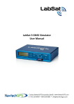
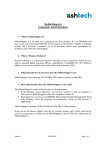
System operation
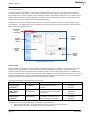
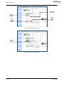
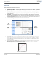
The SatGen v3 GUI is shown below. The GUI will load default values upon start-up. There are two main stages of
scenario production using SatGen. The first stage is to define the trajectory of the test, and the second is to convert
this trajectory into a scenario file which can be replayed on LabSat. The software is designed to be as simple to use as
possible and will need the PC that the software is installed on to be connected to the internet. This will allow for the
Google maps and almanac details to be downloaded automatically.
The SatGen v3 main screen is divided into three sections. The left hand side has the main trajectory selection type
control buttons. The middle section has the trajectory input section and the third right hand section has the Scenario
Details and Scenario Settings sections.
USB security
dongle
recognised
Scenario
details
section
Scenario
trajectory
buttons
Trajectory
set up
section
Scenario
settings
section
Figure 1: SatGen main screen
Security dongle
SatGen v3 software is available as a demonstration or operational product. The SatGen v3 demonstration version is
readily available and will work as normal for demonstration and familiarisation purposes. The demonstration
software is exactly the same as the operational software but without the security dongle inserted. The software will
function as normal with the exception that it will only create a LabSat scenario of only 120 seconds duration. This is to
allow for a demonstration scenario to be created but not of sufficient duration to be of any use as a device testing file.
Operational software will create LabSat scenarios of any duration required.
The dongle is available in three different output variants:
Description
Racelogic Number
Output Capability
Any single constellation scenario
SatGen v3 single
RLLSSGSW03-1
file of the three constellation’s
constellation
available
Any single or dual constellation
SatGen v3 dual
RLLSSGSW03-2
scenario file of the three available
constellation
constellation’s
Any single, dual or triple
SatGen v3 three
RLLSSGSW03-3
constellation scenario file of the
constellation
three constellation’s available
Constellation Available
GPS L1
GLONASS L1
Beidou B1
GPS L1
GLONASS L1
Beidou B1
GPS L1
GLONASS L1
Beidou B1
The software will recognise the USB dongle and display the following status:
SatGen (Version Number) - No dongle detected – Demo version limited to 120 seconds
SatGen (Version Number) – Single, Dual or Three channel enabled
Page | 6
23 July 2014
SatGen v3 Manual
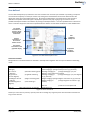
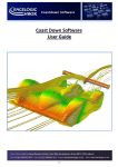
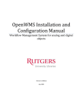
The software dongle once inserted into the USB port will install automatically and will indicate that that it is installed
correctly by displaying a red light.
For normal operation please ensure that the Security Dongle is installed prior to launching the SatGen software and is
recognised by the PC. Please ensure your PC is connected to the internet when installing the dongle for the first time.
This will allow for the automatic download of the relevant drivers for your security dongle.
Figure 2: SatGen software dongle installed in a USB port
Page | 7
23 July 2014
SatGen v3 Manual
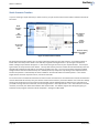
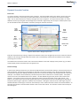
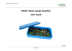
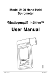
Static Scenario Creation
If you are creating a simple stationary or static scenario, you just use the static scenario button located on the left of
the screen.
Static
scenario
button
Set length of
scenario
required
Set
position
button
Create
scenario
button
Set scenario
time and
date
Scenario setting
more options
tick box
Figure 3: Static scenario creation
By clicking the Set position button you can easily select the location for your static scenario. If the static position is
known then insert the position details in the latitude, longitude and height sections. By clicking the Set position
button a Google map interface will appear. In the search box type the name of your required location. For example
type London, UK and press the search button. The map will instantly move to London UK and automatically insert the
Latitude and Longitude coordinates for the position located on the map. You can pan and zoom using the standard
Google controls and use the standard map or a satellite photo map if required. By clicking on the required scenario
location the position is automatically set into the software. Click the OK button to load the position. Then set the
length of static scenario required in hours, minutes and seconds.
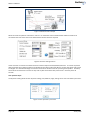
For a basic scenario set the date and start time of the scenario and if the PC is connected to the internet the automatic
almanac download will activate, then just click the Create scenario button. (For further details on the Scenario settings
section go to the dynamic scenario creation section below) Set the LabSat details to LabSat version required and if
you need to change the name of the file, click the change button in the output file box. Fill in the new name in the file
name box, click Save, then OK and the software will create the file. The SatGen progress box will appear giving an
indication of the progress and time until file completion. See figures 4 & 5 below.
Page | 8
23 July 2014
SatGen v3 Manual
Constellation
selection
LabSat
file type
selection
Output
file:
name &
location
Start
scenario
creation
button
Figure 4: Create scenario screen
Scenario
creation
progress
Figure 5: Scenario progress screen
Page | 9
23 July 2014
SatGen v3 Manual
Dynamic Scenario Creation
Draw route
To create a dynamic route click the draw route command. The new window allows you to draw a route on the map
quickly and accurately. By inserting a location description in the search box, any location can be found in Google
maps. You can then easily insert a route by clicking on the map in sequence. The map can be zoomed in or out for
additional accuracy by using the normal Google map commands. Digital maps, terrain maps or satellite photo maps
can be selected and the route edited or cleared by clicking the relevant command.
Draw
route
button
Draw
route
window
Map
zoom
control
Map type
selection
Drawn
route
edit
control
s
Drawn route
in red
Figure 6: Draw route in Google maps screen
Draw the required route by clicking in sequence to draw the route on the Google map the route can then be saved as
a KML file. By clicking on the OK button the drawn route is automatically inserted into the software and is ready for
processing into a scenario.
The software then shows the drawn route in the Scenario details screen with a display of the position (x,y) in meters
and the speed profile in kilometres per hour against time.
Scenario settings
In the Scenario settings section the more tick box should be ticked to reveal further settings. Date and time (UTC) can
easily be defined. The dynamics selected will be reflected in the Scenario Details screen. By selecting High Dynamics
the maximum speed will be 300 kph, Medium Dynamics for a maximum of 100 kph and Low Dynamics for a maximum
of 60 kph. The software will automatically smooth the dynamic data to reflect turns at slower speeds. The update
rate for the route can be defined from 1 Hz to 100 Hz. This will defined the granularity of the route created in the
software. The elevation mask can be set to replicate the antenna environment when using a GPS receiver. This
feature is normally used to improve GPS signal quality when nearby obstacles like trees and building are reflecting or
temporarily obscuring the signal from satellites at low elevation. Raising the mask will cause a GPS engine to ignore
satellites below the mask angle, so must be used carefully as it also reduces the total number of received satellites. So
the higher the elevation mask the fewer satellite in the scenario file created. The elevation mask should normally be
set to 5 degrees.
Page | 10
23 July 2014
SatGen v3 Manual
Figure 7: Elevation mask example
Select the almanac update to automatic or manual. For automatic almanac download the software needs to be
connected via the PC to the internet to download the relevant almanac required.
Figure 8: Scenario settings section
These almanacs are stored in the older Almanacs located in My Documents\SatGen\Almanacs. The initial acquisition
delay should be set to reflect the static time allowed for the device under test (DUT) to acquire the signals and to start
to navigate. As a standard Racelogic recommend 4 minutes to allow for DUT set up and signal acquisition. End delay
should be set to allow for the receiver to stop and any files saved of the DUT performance. Normally set to 30
seconds.
User dynamics input
The dynamics setting allows for four dynamic settings; Low, Medium, High, settings and a user controlled input screen.
Figure 9: User dynamics input screen
Page | 11
23 July 2014
SatGen v3 Manual
Max jerk rate: This controls the maximum rate of change of acceleration in a 2D horizontal plane, a low
setting would allow for slowly increasing acceleration and a high setting giving a rapid change.
Max lat acc: The maximum lateral acceleration controls the maximum acceleration perpendicular to the
direction of travel.
Max long acc: The maximum longitudinal acceleration controls the maximum acceleration/deceleration in
the direction of travel.
Max speed: The maximum speed controls the maximum speed the scenario can achieve.
Max vertical jerk: The Maximum vertical jerk rate controls the rate of change of acceleration in the vertical
direction.
Max vertical accel: The maximum acceleration controls the acceleration in the vertical direction.
SatGen v3 height
When establishing a position solution, a GPS receiver generally works in Earth Centred Earth Fixed (ECEF) coordinates.
It then translates these using a given datum into geodetic coordinates - latitude, longitude, altitude. The datum
specifies an oblate spheroid model for the earth that best approximates the surface of the planet, ignoring all
topographical irregularities; different datum’s can be chosen to best approximate the region of interest to the end
user. SatGen v3 uses the de facto standard World Geodetic System (WGS 84) which is applicable globally.
The initial altitude determined by translating the ECEF X,Y,Z to geodetic latitude, longitude altitude with the WGS 84
datum is an altitude above (or below) the theoretical oblate spheroid and not the surface of the planet in reality. To
derive a more accurate representation of the true altitude, a GPS receiver will then use a model of the earth's
gravitational field to reference the altitude to mean sea level (MSL). Various models exist for these estimates of MSL
around the world, using increasing numbers of coefficients to derive more accurate estimates. The most common are
EGM 84, EGM 96 and EGM 2008. Any altitude you enter into SatGen will be taken as height above MSL and in the
process of simulation, this height will be added to the geoid separation for the current latitude and longitude, as
estimated by the EGM84 geoid model. When generating a simulation from a provided NMEA file containing $GGA
sentences, SatGen does not perform any geoid modelling, but instead uses the geoid separation in addition to the
altitude above MSL provided in the NMEA 0183 GGA sentence
Carrier to noise ratio
SatGen v3 allows for the desired Carrier to Noise ratio (C/No) to be set for GPS and Glonass signals. The maximum
setting which give the strongest signal for GPS is 51 dB-Hz and for Glonass the maximum setting is 57 dB-Hz. Some GPS
engines require a few dB's of noise in order to get lock. The default setting for GPS is 46 dB-Hz and Glonass 52 dB-Hz.
i.e. 5 dB-Hz of added noise.
Start the scenario creation by clicking the Create Scenario button, selecting the LabSat file format as described in the
previous section.
Page | 12
23 July 2014
SatGen v3 Manual
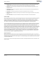
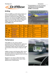
Import File
SatGen v3 allows for the import of three file format:
Load Google Earth KML File -. Google Earth files in KML format can be loaded into the software. The Position
(x,y) and Speed profile is immediately displayed. Date, Time, Dynamics, update rate and mask angle can bet
set to users requirements.
Load NMEA File - NMEA Files in the $GGA format can be loaded into the software. The Position (x,y) and
Speed profile is immediately displayed. Date, Time, (not dynamics), update rate and mask angle can bet set
to users requirements.
Load VBOX File - The VBOX product range a number of high specification GNSS data loggers from Racelogic
ranging from 5Hz to 100 Hz VBOX files in the *.vbo format can be loaded into the software. The Position (x,y)
and Speed profile is immediately displayed. Date, Time, (not dynamics), update rate and mask angle can bet
set to users requirements.
For test scenario files go to the examples sections at the rear of the manual
Load
file
buttons
Coarser
interpolation
button
Smooth
NMEA
button
Figure 10: Import file screen
Smooth NMEA data - This must be ticked before the NMEA file is loaded, this will then apply smoothing to
the data to give a more accurate representation when noise is encountered in the original data. See figure
13: The original data in red and the smoothed data in blue. This is displayed in the scenario details section
once the file is loaded.
Coarse interpolation for large KML files - Very large KML files will exceed the software’s memory limits and
cannot be loaded. If this occurs tick this radio button and the software will use a coarser interpolation
method reducing the size of the memory allocation required.
Figure 11: Smooth NMEA data
Page | 13
23 July 2014
SatGen v3 Manual
User defined
The user defined trajectory input feature is the most versatile of all scenario input methods. By building a simple list
of commands a trajectory can easily be created. By clicking the Preview Button the Scenario details Section will
display the output of the preloaded instructions. By clicking the Help button a full description of the command
definitions and update commands types is displayed. A quick and easy way to get going is to load one of the
predefined examples loaded in the software by clicking the Examples button. This list of predefined user instructions
covers a selection of popular tests to be completed with the SatGen v3 and LabSat combination to test GNSS devices.
Pre-loaded
instructions for
position, height,
speed and turn
instructions
User
command
example list
Preview
instructions in
the scenario
details section
Preview line
instructions in the
graphical display
Help button
displays
instructions
Figure 12: User defined examples screen
Commands available
Recognised user commands details are available in the Help button together with user tips and details of the debug
mode. :
Commands to define initial conditions
Time=xxxxx.xx
{time in seconds from
midnight}
Lat=+xxxx.xx
{latitude of starting point
in degrees}
Long=+xxxx.xx
{longitude of starting
point in degrees}
StartHeight=+xxxx.xx
{height of starting point
in metres}
StartHeading=xxx.xx
{initial heading in
degrees}
Wait xxs
{Wait stationary for xx seconds}
Commands to update trajectory
speed=xxx@yyym
{change velocity to xxx in yyy metres}
speed=xxx@yyys {change velocity to xxx in yyy seconds}
Heading=+xxx@yyym
{change heading by +(or-)xxx
degrees, using radius of yyy metres}
Heading=+xxx@yyys
{change heading by +(or-)xxx degrees
in yyy seconds}
Height=xxx@yyys {change height to xxx metres in yyy seconds}
Height=xxx@yyym
{change height to xxx metres in yyy
metres}
wait xxs
heading for xxs}
{continue at same speed and
Figure 13: User commands
Should you encounter any memory capacity issues when loading very large files please tick the Reduce resolution for
long scenario tick box.
Page | 14
23 July 2014
SatGen v3 Manual
User command examples
A selection of predefined command instructions is available as a set of common user applications. Any of the
examples listed can easily be modified to suit user requirements and saved for later use
User command example files
Acceleration
Circle
Square
Figure of Eight
Airport take off
North Pole Circle
South Pole Circle
Equator Circle
Circle around a set point
Square with stops using repeat command
Rocket
Constant acceleration
Description
Example of a simple acceleration and deceleration
profile.
Simple circle profile.
Simple square profile.
A figure of eight profile.
Take from from a runway.
Circle around the north pole to test latitude and
longitude output.
Circle around the south pole to test latitude and
longitude output.
Circle around the equator to test latitude and longitude
output.
Change the Latitude and longitude settings to move the
circle.
Circuits around a square
Basic rocket trajectory
Standard acceleration command
Figure 14: User command examples
Page | 15
23 July 2014
SatGen v3 Manual
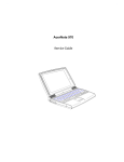
Example data files
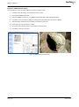
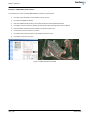
Example 1 – Google KML dynamic scenario
This example uses a pre-recorded KML file to define a dynamic path:
1.
Click the import file button on the SatGen v3 main screen.
2.
Click the Load Google Earth KML File button.
3.
Select the KML file City_London_Cab_route located in My Documents\SatGen\Examples
4.
Click Open in the file selection window and the file will automatically load into the software
5.
Select the date required for the simulation and enter the UTC time
6.
Check that the correct almanac is present
7.
Click the Create scenario button, select LabSat system file name.
8.
Click OK to create your scenario.
Figure 15: KML example file loaded
Page | 16
23 July 2014
SatGen v3 Manual
Example 2 – NMEA dynamic scenario
This example uses a pre-recorded NMEA file to define a dynamic path:
1.
Click the import file button on the SatGen v3 main screen.
2.
Click the Load NMEA File button.
3.
Select the NMEA File Vesuvius_rim_NMEA located in My Documents\SatGen\Examples
4.
Click Open in the file selection window and the file will automatically load into the software
5.
Select the date required for the simulation and enter the UTC time
6.
Check that the correct almanac is present
7.
Click the Create scenario button, select LabSat system file name.
8.
Click OK to create your scenario.
Figure 16: NMEA example file loaded
Page | 17
23 July 2014
SatGen v3 Manual
Example 3 – VBOX VBO dynamic scenario
This example uses a pre-recorded VBOX VBO file to define a dynamic path
1.
Click the import file button on the SatGen v3 main screen.
2.
Click the Load VBOX File button.
3.
Select the VBO file F430-Carolina.vbo located in My Documents\SatGen\Examples
4.
Click Open in the file selection window and the file will automatically load into the software
5.
Select the date required for the simulation and enter the UTC time
6.
Check that the correct almanac is present
7.
Click the Create scenario button, select LabSat system file name.
8.
Click OK to create your scenario
Figure 17: VBOX example file loaded
Page | 18
23 July 2014
SatGen v3 Manual
Appendix:
GGA NMEA format
Define the dynamic profile using a GGA NMEA formatted text message. The GGA format is shown below. SatGen will
properly handle the UTC midnight rollover if it exists in the NMEA input file.
GGA NMEA Format Definition
$--GGA,hhmmss.ss,llll.ll,a,yyyyy.yy,a,x,xx,x.x,x.x,M,x.x,xxx*hh<CR><LF>
hhmmss.ss – UTC of position
lll.ll,a – Latitude –N/S
yyyyy.yy,a – Longitude – E/W
x – GPS Quality indicator – Shall not be a null field
0 – Fix not available or invalid
1 – GPS SPS Mode, fix valid
2 – Differential GPS, SPS Mode, fix valid
3 – GPS PPS Mode, fix valid
4 – Real Time Kinematic. Satellite system used in RTK mode, fixed integers
5 – Float RTK. Satellite system used in RTK mode, floating integers
6 – Estimated (dead reckoning) Mode
7 – Manual Input Mode
8 – Simulator Mode
xx – Number of satellites in use (00-12) may be different from number in view
x.x – HDOP
x.x, M- Altitude, Mean-sea-level (geoid), meters
x.x,M – Geoidal separation, meters
Geoidal Separation: the difference between the WGS-84 earth ellipsoid surface and mean-sea-level (geoid)
surface, “-“ = mean-sea-level surface below WGS-84 ellipsoid surface
x.x – Age of Differential GPS data
Time in seconds since last SC104 Type 1 or 9 update, null field when DGPS is not used
xxxx – Differential reference station ID, 0000-1023
Example GGA Data File
$GPGGA,212331.00,3902.9511,N,10451.2682,W,8,00,0.0,2057.8,M,-15.5,M,,*68
$GPGGA,212332.00,3902.9531,N,10451.2694,W,8,00,0.0,2058.6,M,-15.5,M,,*6F
$GPGGA,212333.00,3902.9548,N,10451.2718,W,8,00,0.0,2059.0,M,-15.5,M,,*62
$GPGGA,212334.00,3902.9559,N,10451.2750,W,8,00,0.0,2059.0,M,-15.5,M,,*69
$GPGGA,212335.00,3902.9565,N,10451.2786,W,8,00,0.0,2059.0,M,-15.5,M,,*6C
Page | 19
23 July 2014
SatGen v3 Manual
Contact Details:
Racelogic Headquarters
German Office
US Office
Racelogic Ltd
Unit 10, Swan Business Centre
Osier Way
Buckingham MK18 1TB
United Kingdom
Racelogic Deutschland
Am Postplatz 5,
35781 Weilburg
Germany
Racelogic USA
27240 Haggerty Rd, Suite E17,
Farmington Hills,
MI 48331
USA
Tel: +44 1280 823803
Fax: +44 1280 823595
Tel: +49 6471 927 996,
Fax: +49 6471 927 770
Tel: +1 248 994 9050,
Fax: +1 248 994 9054
Email: [email protected]
Email: [email protected]
E-mail: [email protected]
Email: [email protected]
Email: [email protected]
Email: [email protected]
Web: www.labsat.co.uk
Web: www.labsat.co.uk
Web: www.labsat.co.uk
Document version control
Revision
3.0
Page | 20
Description
First Release - MS
Date
23/07/2014
23 July 2014