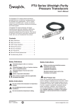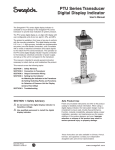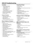
1
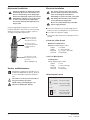
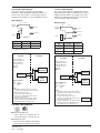
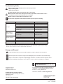
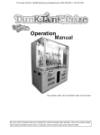
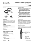
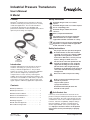
Industrial Pressure Transducers User’s Manual E Model Safety Definitions E Model War ning Potential danger to life or of serious injuries. War ning Potential danger to life or of serious injuries due to catapulting parts. Caution Potential danger of burns due to hot surfaces. Swagelok® industrial pressure transducers allow for electronic monitoring of system pressures in a variety of industrial applications. The E model transducer is specifically designed to meet durability and performance demands of industrial applications where explosion-proof ratings are required. Notice, important information. The product was tested and certified by CSA International. It complies with the applicable Canadian standards on safety. The product was tested and certified by FM Approvals. It complies with the applicable U.S.A. standards on safety. Safety Instructions War ning ® Introduction War ning Swagelok industrial pressure transducers allow for electronic monitoring of system pressures in a variety of industrial applications. The products feature an accuracy of 0.5 % Limit point calibration (0.25 % Best fit straight line), and temperature compensation to ensure accuracy and long term stability when exposed to temperature variations. The transducers are available in a wide variety of pressure connections, pressure ratings, pressure units, and signal outputs to fulfill many application requirements. For proper and safe operation, Swagelok E model transducers must be installed, operated, and serviced according to NEC, applicable local regulations, and these instructions. Otherwise, serious personal injuries, damage or both can occur. The electrical connection provided on the transducer should be used as originally supplied and not bypassed or modified (other than the cable length.) Improper installation or modification of the electrical connection will void the factory warranty and approval. Do not exceed the overpressure rating. War ning War ning Contents Before servicing any installed pressure transducer you must ● depressurize system ● purge the transducer Residual material may be left in the transducer and system. ■ Safety Definitions . . . . . . . . . . . . . . . . . . . . . 1 ■ Safety Instructions . . . . . . . . . . . . . . . . . . . . 1 ■ Mechanical Installation . . . . . . . . . . . . . . . . . 2 ■ Service and Maintenance . . . . . . . . . . . . . . . 2 ■ Electrical Installation . . . . . . . . . . . . . . . . . . 2 ■ Wiring Diagrams . . . . . . . . . . . . . . . . . . . . . . 3 ■ FM and CSA Approvals. . . . . . . . . . . . . . . . . 3 ■ Troubleshooting Guide. . . . . . . . . . . . . . . . . . 4 MS-CRD-PTI-E Rev 2 11-08-WEL War ning Safe Product Use Follow any enclosed instructions and refer to the product catalog for detailed product information. When using a transducer, the total system design must be considered to ensure safe, trouble-free performance. Function, material compatibility, adequate ratings, proper installation, operation, and maintenance are the responsibilities of the system designer and user. Improper selection or misuse of the product may result in serious personal injury or property damage. www.swagelok.com Electrical Installation Mechanical Installation Wa r n i n g Wa r n i n g Check the transducer diaphragm visually for damage. Do not use the transducer if there is visual damage to the diaphragm. The shield / ground connection must be wired to ground to protect the instrument from electromagnetic disturbances. War ning Protect the diaphragm against any contact with abrasive substances, pressure peaks or tools. If you damage the diaphragm, the factory warranty and approval are no longer valid. Attempting to remove the cable connection will damage the transducer and void the factory warranty and approvals. War ning War ning Using the appropriate mating process connection, install the transducer away from excessive heat and vibration whenever possible. Install the system in accordance with NEC requirements. Do not exceed the maximum permissible power supply 30 V (dc). ■ Connect the transducer to a power supply and an indicator or other recording device as shown below. ■ Use a NEC Class 02 power supply ■ Connect the cable shield or the yellow/green wire to ground. Ventilation hole must remain in contact with atmospheric pressure. 4 to 20 mA, 2-Wire System. Use this hex only to secure transducer while installing electrical conduit. Maximum Load Equations Milliampere Output Signal, 2-Wire Output 4 to 20 mA Supply V = 10 to 30 V (dc) Max load RL = (V [dc] – 10) / 0.02 Terminals See drawings Use this hex to install the transducer process connection 1 to 5 V, 3-Wire System Load Equations 50 N·m (36 ft·lb) max Voltage Output Signal, 3-Wire Output 1 to 5 V Supply V = 10 to 30 V (dc) Min Load RL > 5 k Terminals See drawings Service and Maintenance Swagelok E model pressure transducers are tested and calibrated at the factory. There are no user serviceable components inside the case. Cau t i o n The surfaces of the pressure transducer may get hot during operation. War n i n g Liquid leaking from diaphragm is an indicator of diaphragm damage. Wiring Diagram Legend Power Supply (+) V dc+ Plus power supply (–) 0 V dc Minus power supply (common, ground) Load (+) S+ Plus output signal (–) S– Minus output signal (common, ground) MS-CRD-PTI-E Rev 2 11-08-WEL 4 to 20 mA, 2-Wire System 1 to 5 V, 3-Wire System The 2-wire system connects the power supply, transducer, and indicating/recording instrument in a series circuit. This creates a “current loop” with the transducer functioning as a current regulation device. The 3-wire system features separate leads for the signal and power supply. The third lead is common negative for both devices. The signal source and indication/recording instruments are connected in series, the power supply in parallel. Wiring Diagram (+) Power supply 4 1 Wiring Diagram (+) V dc+/S+ (+) (-) 3 (+) (1) Red (-) (–) 2 (-) (2) Black (+) Load (+) 0 V dc/S– A 4 3 (-) 1 2 B D (1) Red (–) C (3) Brown S+ (+) (+) (–) (+) V dc+ Power supply (2) Black Load (–) Wire Coding Color V dc+/S+ Red Wire Coding Color Black Supply + V dc+ Red Supply – Signal – 0 V dc/S– Black Signal + S+ Brown 0 V dc/S– Use yellow/green wire or braided conductor for shield/ground connection. Hazardous (Classified) Location Nonhazardous Location Class I, Division 1, Groups A, B, C, D Class II, Division 1, Groups E, F, G Class III (Note 1) 0 V dc/S– Control Equipment Pressure Transducer Maximum Ratings: Vmax = 30 V, Imax = 100 mA, Pi = 1 w 0 V dc+/S+ Notes 1.Dust-tight conduit seal must be used when installed in Class II and Class III environments. 2. NEC Class 02 power supply. 3. For types with cable: Seal conduit. 4.No revision to drawing without prior Factory Mutual Research Approval. 5.Install the transducer in accordance with the National Electrical Code (ANSI/NFPA 70) or Canadian Electrical Code (CEC) Part 1. FM and CSA Approval Power Supply (Note 2) Hazardous (Classified) Location Class I, Division 1, Groups A, B, C, D Class II, Division 1, Groups E, F, G Class III (Note 1) Pressure Transducer Maximum Ratings: Vmax = 30 V, Imax = 100 mA, Pi = 1 w S V dc– V dc+ (+) (–) 0 V dc/S– Supply + Signal - (–) Nonhazardous Location Control Equipment Power Supply (Note 2) Notes 1.Dust-tight conduit seal must be used when installed in Class II and Class III environments. 2. NEC Class 02 power supply. 3. For types with cable: Seal conduit. 4.No revision to drawing without prior Factory Control drawing number 209752 Mutual Research Approval. 5.Install the transducer in accordance with the National Electrical Code (ANSI/NFPA 70) or Canadian Electrical Code (CEC) Part 1. ■ FM and CSA approval: ■Class I, Division 1, Groups A, B, C, D ■Class II/III, Division 1, Groups E, F, G ■ Temperature class: ■T6 at maximum ambient 140°F (60°C) ■T4 at maximum ambient 221°F (105°C) MS-CRD-PTI-E Rev 2 11-08-WEL A D B C Troubleshooting Guide War n i n g Before servicing any installed pressure transducer you must ● depressurize system ● purge the transducer Residual material may be left in the transducer and system. ■ If the transducer becomes damaged or unsafe for operation, remove it from service and mark to prevent it from being used accidentally. War n i n g ■ Have repairs performed by the manufacturer only. Do not insert any pointed or hard objects into the pressure port for cleaning. Problem Possible Causes Remedy Power supply failure Check power supply Open wiring Check continuity Wiring reversed Correct polarity No pressure or port blocked Check pressure port Transducer failure due to wrong supply voltage or power surge Replace transducer Pressure port blocked Check pressure port Transducer over-pressurized Replace transducer Transducer failure due to wrong supply voltage or power surge Replace transducer Supply voltage too low Check voltage supply Load impedance wrong Adjust load or supply voltage Transducer overpressurized Replace transducer➀ Zero signal too low Transducer overpressurized Replace transducer➀ Zero signal too high Transducer overpressurized Replace transducer➀ Non-linear output Transducer overpressurized Replace transducer No output Output steady as pressure changes Full span output low ➀A djusting the controller or display device can usually compensate for small changes in the output signal. Test the system for proper operation after adjustments are made. An excessive change in the output signal indicates possible transducer damage. This may cause the output to be non-linear, requiring transducer replacement. Storage and Disposal Purge all media from the pressure transducer before storage or disposal of the transducer. Wa r n i n g Mount the protection cap when storing a flush diaphragm pressure transducer to prevent damage. Dispose of transducer components and packaging materials in accordance with the respective waste treatment and disposal regulations of the region or country to which the transducer is supplied. Do not mix or interchange parts with those of other manufacturers. Swagelok Company 29500 Solon Road Solon Ohio 44139 U. S. A. For product technical data, including materials of construction, see the Swagelok Industrial Pressure Transducers catalog, MS-02-225. Authorized Representative in Europe: Translations available on www.swagelok.com. Swagelok A.G.—Manufacturing Tech Center / Distribution Center P.O. Box 552 CH-8853 Lachen, Switzerland Swagelok—TM Swagelok Company © 2004, 2008 Swagelok Company MS-CRD-PTI-E, R2 November 2008 MS-CRD-PTI-E Rev 2 11-08-WEL