1
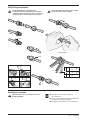
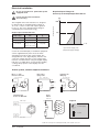
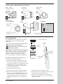
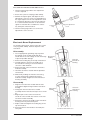
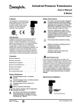
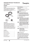
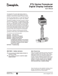
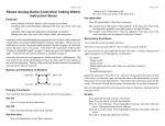
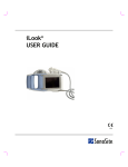
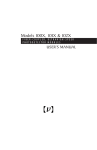
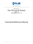
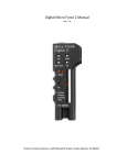
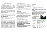
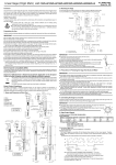
PTU Series Ultrahigh-Purity Pressure Transducers User’s Manual The Swagelok® PTU series pressure transducer provides electronic monitoring of system pressure for ultrahigh-purity applications. The PTU series transducer is available with a variety of pressure ranges, process connections, electrical connections, and output signals. A Swagelok PTU series transducer will require mechanical and electrical installation; additionally, a set-up and/or adjustment procedure may be required to prepare the unit for service. This manual is intended to provide the instructions necessary to install, start-up, and troubleshoot the product. Contents ■ Safety Definitions . . . . . . . . . . . . . . . . . . . . . 1 ■ Safety Instructions . . . . . . . . . . . . . . . . . . . . 1 ■ VCR® Fitting Installation . . . . . . . . . . . . . . . . 2 ■ Welding Precautions . . . . . . . . . . . . . . . . . . 2 ■ Electrical Installation . . . . . . . . . . . . . . . . . . 3 ■ Zero Adjustment . . . . . . . . . . . . . . . . . . . . . . 4 ■ Electronic Board Replacement . . . . . . . . . . 5 ■ Troubleshooting Guide . . . . . . . . . . . . . . . . . 6 Safety Definitions Wa r n i n g Potential danger to life or of serious injuries. Wa r n i n g Potential danger to life or of serious injuries due to catapulting parts. Caution Potential danger of burns due to hot surfaces. Safety Instructions War ning Residual material may be left in the transducer and system. Notice, important information. The product complies with the applicable European directives. Safety Instructions Wa r n i n g Do not connect the transducer to hazardous voltage. Wa r n i n g Use qualified personnel to install the transducer. Do not exceed the overpressure rating. Wa r n i n g MS-CRD-PTU1 Rev 2 10-08-WEL Before servicing any installed pressure transducer you must ● depressurize system ● purge the transducer War ning Safe Product Use Follow any enclosed instructions and refer to the product catalog for detailed product information. When using a transducer, the total system design must be considered to ensure safe, trouble-free performance. Function, material compatibility, adequate ratings, proper installation, operation, and maintenance are the responsibilities of the system designer and user. Improper selection or misuse of the product may result in serious personal injury or property damage. www.swagelok.com VCR Fitting Installation Swagelok VCR face seal fitting end War n i n g connections with fixed threads must remain stationary during installation. Do not allow the sealing beads to rotate against the gasket. War ning Over tightening will damage the sealing beads and may cause leakage. 6 1 GTAW 2 3 7 Finger-tight GTAW 4 5a SS 8 45° Ni 90° Cu 5 5b 5c Welding Precautions War n i n g Qualified personnel should perform the welding (GTAW). ■ Disconnect the transducer from any electrical device. ■ Do not let the leads from the flying lead touch a metal surface during welding. ■ Keep heat to the transducer to a minimum. MS-CRD-PTU1 Rev 2 10-08-WEL N-ELD-0909 SWAGELOK TRANSDUCERS OUTPUT SIGNAL FLOW CURVE Electrical Installation Wa r n i n g Do not exceed the max. permissible power supply DC 30 V. Wa r n i n g Power must be turned off before disconnecting. Required Input Voltage for Current (4 to 20 mA) Output Transducers 1000 Allowable Load The Swagelok PTU series transducer is designed to operate with an unregulated input voltage of 10 < V dc < 30 (14 to 30 V with output signal 0.1 to 10.1 V). The exact operating input voltage is controlled by the load resistance (RL). Output signal and allowed load Transducer Output Type Input Power V dc Allowable Load RL 0.1 to 5.1 V dc 10 to 30 >5K 14 to 30 > 10 K 0.1 to 10.1 V dc Max 30 V dc 4 to 20 mA (0.02 RL + 10 V dc) (0.02 RL + 16 V dc)➀ 500 0 See graph 0 10 ➀Use this load equation when a PTU series digital display 20 30 V dc Input Power Supply V dc (Required Supply Voltage) indicator is used. Current for external display or evaluation equipment can be supplied directly from the circuit when operating a transducer with current output. The Swagelok PTU series digital display indicator has a specific voltage drop of 6 V. This voltage drop must be considered when using the digital display indicator; see table above. If using another display, a voltage drop specific to that display must be considered. 2-wire system, current output transducers Direct wire, flying leads (+) V dc+/S+ M 12 1, 4 pin Circular connector (+) V dc+/S+ Bendix, 4 pin MIL plug (+) V dc+/S+ red (-) 4 3 1 2 (1) (-) (-) black (-) (+) (+) 0 V dc/S– (-) (-) (2) (+) 0 V dc/S– A D B C 0 V dc/S– 15 pin Sub-D Tajimi Circular Connector R03-R6F V dc+/S+ + 5 (-) A C 4 3 E 2 (-) 1 RL + Legend (+) UB+ / Sig+ 0 V / Sig- 10 9 8 7 6 15 (+) 14 13 (–) Power Supply 12 11 (+) (–) Load (+) 0 V dc/S– NOTE: Pin 5 and pin 12 are bridged internally in the sub-D connector. MS-CRD-PTU1 Rev 2 10-08-WEL 3-wire system, voltage output transducers Direct wire, flying leads M 12 1, 4 pin Circular connector (+) V dc+ S+ (+) 4 3 (–) 1 2 Bendix, 4 pin MIL plug V dc+ (+) red V dc+ (1) (–) (+) S+ (–) 0 V dc/S– Tajimi Circular Connector R03-R6F + 15 pin Sub-D 3 2 S+ C 0 V dc/S– 1 10 9 8 7 6 15 (+) 14 Power Supply 13 (–) 12 (+) 11 Load (–) RL + - (+) 5 4 (-) C D B Legend - E A S+ (–) 0 V dc/S– (+) A (+) (2) V dc+ UB+ Sig + (3) black (+) (–) (–) brown 0 V / Sig- (-) 0 V dc/S– NOTE: Pins 5 and 12 are internally connected Zero Adjustment The Swagelok PTU series transducer is factory calibrated and does not normally need field adjustment. Cau t i o n The surfaces of the pressure transducer may get hot during operation. pan adjustment is not necessary after S zero point correction. Threaded locking ring Connector assembly Keyed insertion point For verification and adjustment of the zero point, depressurize the system to 0 psig (0 bar, 0 MPa) for gauge reference transducers. The potentiometer for the zero adjustment is protected inside the transducer housing. Use a 0.040 to 0.060 in. (1 to 1.5 mm) jeweler’s screwdriver for adjustment. Procedure for Transducer with Top Access 1. Remove power to the transducer. Pressure transducer housing Zero adjustment screw 2. Remove the threaded locking ring on the top of transducer and gently extend the electrical connection to expose the zero adjustment screw. 3. Carefully pull the connector assembly out of the transducer housing as far as the internal connector cable will allow. 4. Restore power to the transducer. 5. Ensure the system is at 0 psig (0 bar, 0 MPa). 7. Remove power to the transducer again. 6. Monitor the output signal, and adjust the zero screw to 4 mA or 0.1 V depending on the signal output. Turn the zero adjustment screw in a clockwise direction to increase the signal or in a counterclockwise direction to decrease the signal. 8. Rotate the connector assembly on the transducer housing to the keyed insertion point. MS-CRD-PTU1 Rev 2 10-08-WEL 9. Replace and hand tighten the locking ring on the top of transducer to close access to the zero adjustment screws. Procedure for Transducer with Side Access 1. Turn the locking ring until the zero adjustment screw is exposed. 2. Ensure the system is at 0 psig (0 bar, 0 MPa). 3. Monitor the output signal, and adjust the zero adjustment screw to 4 mA or 0.1 V depending on the signal output. Turn the zero adjustment screw in a clockwise direction to increase the signal or in a counterclockwise direction to decrease the signal. Do not allow the screwdriver to contact any other part of the transducer. Locking ring Zero adjustment screw 4. Turn the locking ring until access to the zero adjustment screw is closed. Electronic Board Replacement For module replacement, depressurize the system to 0 psig (0 bar, 0 MPa). Remove all power to the transducer. Disassembly 1. Use an appropriate grounding strap to protect the printed circuit module (PCB) and other electrical devices from voltage or static discharge to prevent possible damage. Electronics module 2. Remove the locking ring on the top of transducer. 3. Carefully pull the connector assembly out of the transducer housing, as far as the internal connector cable will allow. Pressure transducer housing 4. Remove the pin connector from the electronics module assembly. 5. Hook the electronics module with the provided removal tool. 6. While firmly holding the transducer housing, use the removal tool to pull the electronics module assembly straight out of the transducer housing assembly. Transducer with Top Access Reassembly 1. Align the new electronic module with the slots in the plastic alignment ring inside the transducer housing. 2. Firmly push the new electronics module assembly into the transducer body as far as it will go. Electronics module Pressure transducer housing 3. Align the pins on the connector from the electrical connector with the sockets on the new electronic module assembly. 4. Rotate the connector assembly on the transducer housing to the keyed insertion point. 5. Replace and hand tighten the locking ring on the top of transducer. 6. Restore power to the transducer and verify the zero point. Transducer with Side Access MS-CRD-PTU1 Rev 2 10-08-WEL Troubleshooting Guide War n i n g Before servicing any installed pressure transducer, you must ● depressurize the system ● purge the transducer Residual material may be left in the transducer and system. ■ If the transducer becomes damaged or unsafe for operation, remove it from service War n i n g and mark to prevent it from being used accidentally. ■ Have repairs performed by the manufacturer only. Do not insert any pointed or hard objects into the pressure port for cleaning. Problem Possible Causes Remedy Failure of power supply Check power supply and wiring Wiring interrupted Replace defective components Transducer miswired Check wiring Defective electronics Change electronics module Defective electronics Change electronics module Transducer failure through over‑pressurization Replace transducer Defective electronics Change electronics module Supply voltage too low Adjust supply voltage Full span reading too low Load impedance too high Adjust supply voltage (See Output signal and allowed load table in Section 4) Zero signal too low Zero adjustment made incorrectly Adjust zero point No signal output Steady signal despite pressure variation Steady, elevated signal despite pressure variation Zero adjustment made incorrectly Adjust zero point Zero signal too high Transducer failure through over‑pressurization Replace transducer Non-linear signal output despite correct zero adjustment Transducer failure through over‑pressurization Replace transducer Storage and Disposal Purge all media from the pressure transducer before storage or disposal of the transducer. Wa r n i n g Mount the protection cap when storing the transducer. Dispose of transducer components and packaging materials in accordance with the respective waste treatment and disposal regulations of the region or country to which the transducer is supplied. Do not mix or interchange parts with those of other manufacturers. Swagelok Company 29500 Solon Road Solon Ohio 44139 U. S. A. For product technical data, including materials of construction, see the Swagelok® Pressure Transducers, Ultrahigh-Purity catalog, MS-02-162. Authorized Representative in Europe: Swagelok A.G.—Manufacturing Tech Center / Distribution Center P.O. Box 552 CH-8853 Lachen, Switzerland Swagelok,VCR—TM Swagelok Company Bendix—TM Amphenol Corporation © 2003, 2006, 2008 Swagelok Company MS-CRD-PTU1 Rev 2 10-08-WEL