1
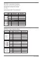
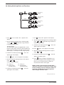
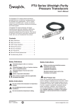
PTU Series Transducer
Digital Display Indicator
User’s Manual
The Swagelok® PTU series digital display indicator is
available to mount directly to the Swagelok PTU series
transducer to provide local indication of system pressure.
The PTU series digital display is a 4-digit, LED display with
user configurable units of psi, bar, kg/cm2, KPa, and MPa.
The product is available in front view or top view to conform
with the mounting orientation. This digital display provides
0.5 % to +/– 1 digit accuracy, includes two programmable
set points (one with Bendix connection), and is available
with a variety of electrical connectors and output signals
to the match the PTU series transducer. The operation at
the PTU series digital display indicator requires connection
to the transducer, electrical connection of power supply,
and set-up of the unit to correspond to the transducer.
This manual is intended to provide general instruction
necessary to install, start-up, and troubleshoot the product.
This manual covers the following topics:
SECTION 1: Safety Advisory
SECTION 2: Connection to Transducer
SECTION 3: Output Connection Wiring
SECTION 4: Setting Up the Indicator
4a: Matching the Indicator to the Transducer
4b: Setting Switching Points and Functions
4c: Selection of Pressure Unit for Display
4d: Zero Point Offset
SECTION 5: Troubleshooting
SECTION 1: Safety Advisory
Safe Product Use
! Do not connect the digital display indicator to
Follow any enclosed instructions and refer to the product
catalog for detailed product information. When using a
digital display indicator, the total system design must be
considered to ensure safe, trouble-free performance.
Function, material compatibility, adequate ratings, proper
installation, operation, and maintenance are the responsibilities of the system designer and user. Improper
selection or misuse of the product may result in
serious personal injury or property damage.
hazardous voltage.
! Use qualified personnel to install the digital
display indicator.
These instructions are also available in Chinese, French,
German, and Japanese. Contact your independent
Swagelok sales and service representative.
MS-CRD-PTU2
Revision 0 5-03-CP
www.swagelok.com
SECTION 2: Connection to Transducer
Various types of connections are available. Make sure
that the indicator connections match the transducer
connections and the connection lines of the voltage
power supply.
Connection jacks are available for direct attachment to the
Bendix, 4 pin MIL plug, or M12 1, 4 pin circular connector.
Connector
Pin
2-Wire System,
Current Output
3-Wire System,
Voltage Output
Circular connector (female) M 12 1, 4 pin
1
Power supply V dc+, S+
Power supply V dc+
2
—
—
3
Power supply 0 V dc, S–
Power supply 0 V dc, S–
4
—
Signal, S+
A
Power supply V dc+, S+
Power supply V dc+
Bendix MIL-connector (female) 4 pin
B
—
Signal S+
C
—
—
D
Power supply 0 V dc, S–
Power supply 0 V dc, S–
SECTION 3: Output Connection Wiring
Connector
Pin
2-Wire System,
Current Output
3-Wire System,
Voltage Output
1
Power supply V dc+, S+
Power supply V dc+
2
Switch out1
Switch out1
3
Power supply 0 V dc, S–
Power supply 0 V dc,
Switch ground, S–
4
Switch ground (potential-free)
Signal S+
5
Switch out2
Switch out2
red
Power supply V dc+, S+
Power supply V dc+
black
Power supply 0 V dc, S–
Power supply 0 V dc
Switch ground, S–
yellow
Switch ground (potential-free)
Signal S+
brown
Switch out1
Switch out1
orange
Switch out2
Switch out2
A
Power supply V dc+, S+
Power supply V dc+
B
Switch ground (potential-free)
Signal S+
C
Switch out1
Switch out1
D
Power supply 0 V dc, S–
Power supply 0 V dc,
Switch ground, S–
Circular connector M 12 1, 5 pin
Flying leads
R
B
Y
B
O
Bendix MIL-connector (male) 4 pin
2
MS-CRD-PTU2
Revision 0 5-03-CP
SECTION 4: Setting Up the Digital Display Indicator
Function
Key functions
The following functions are available:
SET
Set switching points and functions (hold two seconds)
▲
Increase unit
▼
Decrease unit
■ Pressure unit selection
■ Decimal point position
■ Setting lowest display value
■ Setting highest display value
■ Switching point setting for output 1
■ Switching function setting for output 1
SET
+
▲
Input zero point offset (hold five seconds)
SET
+
▼
Configuration (hold five seconds)
■ Switching point setting for output 2
(Flying lead and M12 only)
■ Switching function setting for output 2
(Flying lead and M12 only)
■ Display unit selection
■ Zero point correction
4a: Matching the Indicator
to the Transmitter
SET
Display
▼
▲ ▼
unit
(5 s)
Set unit;
confirm
SET
SET
▲ ▼
dP
Set decimal
point;
confirm
SET
SET
SET
di.Lo
▲ ▼
Set lowest
display value;
confirm
SET
SET
di.Hi
▲ ▼
Set highest
display value;
confirm
SET
1. Press
SET
and
▼
simultaneously for five seconds;
▲
and
▼
. The selected unit
3. Confirm the set value by pressing
SET
; “unit” appears
10. Press
SET
briefly; “di.Hi” (display high) appears in the
11. Set the highest display value using
▲
and
▼
.
This value should match the maximum pressure
again in the display.
SET
; “di.Lo”
display.
should match the unit of the transducer.
4. Press
SET
appears again in the display.
the display will show “unit.”
2. Select the unit using
9. Confirm the set value by pressing
briefly; “dP” (decimal point) appears in
rating of the transducer.
12. Confirm the set value by pressing
the display.
SET
; “di.Hi” appears
again in the display.
5. Select the required position of the decimal point using
▲
and
▼
13. Press
.
6. Confirm the set value by pressing
7. Press
briefly; the display disappears for a short
time and consequently signals that the settings have
SET
; “dP” will
been taken over in the internal memory. Afterwards
again appear in the display.
SET
SET
the measured value is displayed again.
again; “di.Lo” (display low) appears in
the display.
8. Set the lowest display value using
▲
and
▼
.
This value should match the minimum pressure rating
of the transducer.
MS-CRD-PTU2
Revision 0 5-03-CP
NOTE: If no key is pressed for ten seconds when
setting the instrument, it automatically changes back
into the overriding menu level. After 60 seconds, the
instrument automatically exits the configuration
menu. Changes will not be saved.
3
4b: Setting Switching Points and Functions
▲ ▼
SET
SP 1
Display
(2 s)
Set switching
point 1;
confirm
SET
SET
▲ ▼
out1
Select switching
function 1;
confirm
SET
Bendix
SET
SET
➀
SP 2
▲ ▼
Set switching
point 2;
confirm
SET
SET
➀
out2
▲ ▼
Select switching
function 2;
confirm
SET
Flying lead and M12
1. Press
SET
for two seconds; “SP 1” appears in the
display.
▲
and
▼
(permissible range: minimum
to maximum display value).
3. Confirm the set value by pressing
SET
; “SP 1” will
SET
again; “out1” will appear in the display.
5. Select the required switching function of the output 1
▲
and
▼
.
▲
and
▼
(permissible range: minimum to
maximum display value).
; “SP 2” will
appear again in the display.
10. Press
SET
again; “out2” appears in the display.
11. Select the required switching function of output 2
using
▲
and
▼
.
SET
; “out2” will
appear in the display again.
13. Press
SET
briefly; the display will disappear for a
short time and signals that the settings have been
measured value will be shown again.
on: always on
nc: break contact
(normally closed)
6. Confirm the selection by pressing
again appear in the display.
SET
; “out1” will
NOTE: If no key is pressed for ten seconds when
setting the instrument, it automatically changes back
into the overriding menu level. After 60 seconds, the
instrument automatically exits the configuration
menu. Changes will not be saved.
➀
4
SET
taken over in the internal memory. Finally, the
Four possibilities are given:
off: always off
no: make contact
(normally open)
using
12. Confirm the selection by pressing
appear again in the display.
using
briefly; “SP 2” appears in the display.➀
9. Confirm the set value by pressing
Scrolling function:
The up and down arrows are equipped with a “scroll
function” to enter values. If the key is pressed briefly, the
display value will change by one digit. If the key is held
down longer (> 1 second), the value changes quickly.
4. Press
SET
8. Set the required switching point for switching output 2
2. Set the required switching point for switching output
1 using
7. Press
Flying lead and M12 only.
MS-CRD-PTU2
Revision 0 5-03-CP
4c: Selection of Pressure Unit for Display
1. Select the required unit using
▲
and
▼
.
NOTE: Not all units are available on all digital display
indicators.
4d: Zero Point Offset
Offsetting the zero point makes it possible to correct
display errors which are the result of sensor tolerances.
The value entered here is subtracted from the measured
result, i.e. the characteristic curve is offset parallel to the
zero point.
1. Press
SET
and
▲
for five seconds; “OFFS” (offset)
2. Enter the required zero point offset using
and
▼
(permissible range: + 12.5 % of
display span).
3. Confirm the set value with
SET +
Display
▲
SET
4. Press
SET
OFFS
▲ ▼
SET
Zero point
adjustment;
confirm
briefly; the measured value is displayed
again.
appears in the display.
▲
(5 s)
SET
; “OFFS” again appears
NOTE: If no key is pressed for ten seconds when
setting the instrument, it automatically changes back
into the overriding menu level. After 60 seconds, the
instrument automatically exits the configuration
menu. Changes will not be saved.
in the display.
SECTION 5: Troubleshooting
Error Message
Possible Reason
Remedy
Overpressure
Error resets itself when signal is
within range.
Transducer defective or not suitable
Check the transducer.
Transducer connection cable is
short circuited
Check the transducer connection lines.
Input signal too low
Error resets itself when signal is
within range.
Transducer defective or not suitable
Check the transducer.
Transducer connection cable is
short circuited
Check the transducer connection lines.
Err. 3: Display range exceeded
The maximum possible display value of 6000
has been exceeded.
The display value cannot be displayed
in the selected unit
Error resets itself when the measured
value is within the display range.
Err. 4: Measuring range exceeded
The minimum possible display value of –999
has not been achieved.
The display value cannot be displayed
in the selected unit.
Error resets itself when the measured
value is within the display range.
Err. 1: Measuring range exceeded
The measuring range of the transducer has
been exceeded by greater than 2 % of the
measuring range span.
Err. 2: Signal below measuring range➀
The measuring range of the transducer falls
short of the measuring range span by greater
than 2 %.
➀ The keys are blocked as long as the error message Err.2 is displayed.
Caution: Do not mix or interchange parts with those
of other manufacturers.
MS-CRD-PTU2
Revision 0 5-03-CP
5