1
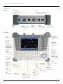
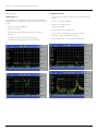
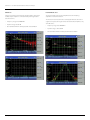
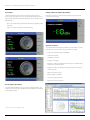
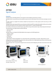
CellAdvisor™
JD725A Dual-Port Cable and Antenna Analyzer
Many modern wireless base stations are a complex system of multiple
RF components, such as low-noise amplifiers (LNA), duplexers, and
tower-mounted amplifiers (TMA), whose performance directly affects
the cell site's coverage and capacity. Having the right instrument to
service and verify that these components are functioning properly is
essential.
The JD725A CellAdvisor Analyzer includes all of the necessary measurements functions
to perform RF component measurements, including insertion gain, insertion loss,
antenna isolation, TMA performance, and duplexer antenna verification. It also accurately
characterizes a site's antenna system, including voltage standing wave ratio (VSWR), distance
to fault (DTF), cable loss, and power measurements.
The JD725A CellAdvisor field instrument is easy to use and is equipped with a color touchscreen display for taking quick measurements and displaying results clearly. Its JDViewer
application software lets users easily compare and analyze measurements as well as generate
professional reports. Designed for field test use, the JD725A has a rechargeable fieldreplaceable lithium-ion (LiON) battery that can operate continuously for more than 5 hours*.
Features and Benefits
• Portable, lightweight handheld instrument
• Built-in wireless frequency bands and the most
commonly used RF cable types
• 7 in color TFT touch-screen display
• Superior immunity to RF interferences
• Up to 1001 data points for high-resolution and
long-distance problem location
• USB port for an external USB memory device
• Saves up to 400 measurement traces,
100 measurement screens, and 20 userdefinable setups
• Interfaces with JDViewer application software
to manage data and create reports
• On-screen keyboard lets users save files
quickly and easily
• Rechargeable, field-replaceable lithium-ion
battery
Key Measurements
Advanced Functions
• VSWR
• Trace overlay lets users comparatively analyze up to four traces on one measurement
screen
• Return loss
• Provides up to three marker bands in addition to its six markers
• Reflection measurements are shown in VSWR, return loss, or Smith charts
• DTF
• Cable loss
• Insertion loss
• Insertion gain
• Power meter
• RF source
*Available only for serial number 1406G6331 and later.
www.jdsu.com/nse
Data Sheet
CellAdvisor — JD725A Dual-Port Cable and Antenna Analyzer
Panel Overview
Top View
RF Out/Reflection
50 ohm N-type RF connector
to measure VSWR, DTF, and
one-port cable loss
DC 15 V IN
External DC
input port
RF In
50 ohm N-type RF connector, in conjunction
with RF Out/Reflection port, to measure
amplifier gain and cable insertion loss
LAN
Ethernet
Ethernet communication
port to connect a PC with
the application SW
USB Client
USB port to
connect a PC with
the application SW
USB Host
USB memory stick port,
used to save measurement data or upgrade
instrument firmware
SERIAL
D-sub serial interface port
to connect an optional
external power sensor
Front View
VSWR
Measures impedance
matching
7 INCH COLOR LCD
Daylight viewable
high-resolution LCD
display
DTF
Measures distance to
fault location
SCREEN MENU
Displays selectable
menu in connection
with function keys or
soft keys
GAIN/LOSS
Measures amplifier gain
and cable insertion loss
POWER METER and
SIGNAL GENERATOR
Measures transmission
power and generates a
CW signal
ESC
Cancels latest
selection or moves
to previous menu
SYSTEM
Presents system
information or upgrades
the instrument's firmware
SPEAKER
Generates audio, if
enabled, for alarms and
key selections
KNOB & UP/DOWN
Moves an item's marker
position on the table list
CAL
Performs calibration
for VSWR, DTF, cable
loss, and gain/loss
measurements
POWER & LED
Power ON/OFF
Green LED:
Power ON status
Red LED:
External power
SCALE
Changes Y-axis
scale, VSWR or
return loss or
Smith chart
LOAD
Recalls saved traces to
compare with current
or other saved traces
MARKER
Supports six markers
for each trace
AMP
Sets Y-axis Min /Max,
limit, and limit level
www.jdsu.com/nse
LIGHT
Sets LCD brightness
SAVE
Saves screen,
trace, and setup
FREQ/DIST
Sets frequency range or selects
a standard or custom frequency
band. Sets distance and selects
standard or custom cables
AUTO SCALE
Adjusts Y scale on
screen for optimal
trace display
HOLD
Pauses current
ENTER
Finishes an measurement display
"entry," which
is thevalue or
test parameter
TRACE POINT
Selects trace points among
PEAK
126, 251, 501, or 1001
Identifies the highest
peak of the trace
TRACE
Captures up to 4 traces
Assigns saved trace to
trace number
2
CellAdvisor — JD725A Dual-Port Cable and Antenna Analyzer
Main Functions
DTF (Distance to Fault)
VSWR / Return Loss
• The DTF measurement function lets users accurately identify faulty
locations.
VSWR and Return Loss measurements show impedance performance
and signal reflection characteristics for cables, connectors, and antenna
systems.
• Frequency range: 25 to 4000 MHz
• Distance: Up to 1250 m (4125 ft)
• Frequency range: 25 to 4000 MHz
• Dynamic range: 60 dB
• Dynamic range: 60 dB
• High-resolution mode with 1001 points
• Over 80 wireless frequency bands built into the instrument’s
database
• Over 95 cable types built into the instrument’s database
• Flexibility to incorporate additional frequency bands
• User-definable limit line for fast pass/fail characterization
www.jdsu.com/nse
• Flexibility to incorporate additional cable types
• User-definable limit line for fast pass/fail characterization
3
CellAdvisor — JD725A Dual-Port Cable and Antenna Analyzer
Cable Loss
Insertion Gain / Loss
Cable Loss measures the amount of signal lost by the cable line to
facilitate rapid compliance verification analysis throughout the
transmission line.
The Insertion Gain measurement simplifies the task of verifying
amplifiers and antenna isolation.
• Frequency range: 25 to 4000 MHz
• Dynamic range: 0 to 30 dB
• User-definable limit line for fast pass/fail characterization
The Insertion Loss measurement accurately quantifies the amount of
signal loss as it passes through a cable, attenuator, filter, amplifier, or any
other RF device.
• Frequency range: 25 to 4000 MHz
• Dynamic range: –90 to 50 dB
• User-definable limit line for fast pass/fail characterization
www.jdsu.com/nse
4
CellAdvisor — JD725A Dual-Port Cable and Antenna Analyzer
Power Meter
CW Signal Generator (Option JD725A002)*
The Power Meter function easily and comprehensively measures
power using external power sensors. Its configurable settings let users
display range, maximum and minimum limits, and select power units in
dBm or Watts.
Provides a sine wave or continuous wave (CW) source for small cell
coverage or DAS testing.
• Users can set lower/upper power limits for fast testing with pass/fail
indication
• Power sensor types: directional and terminating
Application Software
The JD725A JDViewer Application Software provides all the necessary
tools for more convenient instrument operation, including:
• Instrument communication via LAN/USB
• Smith chart support
• VSWR-DTF conversion
• Captures saved plots
• Registers or edits user-definable wireless frequency bands into the
instrument’s custom bands list
• Registers or edits user-definable cable types into the instrument’s
custom cable list
• Edits measurement charts
• Report templates available
• Generates and prints reports
• Exports measurement reports
Bias Tee (Option JD725A001)
The optional built-in Bias Tee lets users choose voltages between 12 V
and 24 V in 3 V increments on the RF IN port, eliminating the need for an
external power supply.
*Available only for serial number 1406G6331 and later
www.jdsu.com/nse
5
CellAdvisor — JD725A Dual-Port Cable and Antenna Analyzer
Advanced Functions
The JD725A CellAdvisor provides additional functions for superior analysis.
Trace Overlay
Trace Overlay enables comparative analysis of up to four traces by
superimposing them together on one measurement graph.
Additionally, users can set up to six markers on any trace among
multiple traces to view corresponding values.
Specifications*
General
Max input power
+25 dBm, ±50 V DC
Frequency range
25 to 4000 MHz
Frequency accuracy
<± 75 ppm
Frequency resolution
100 kHz
Test port impedance
50 Ω
Test ports
Type N Females
Trace storage
Up to 400
Screen storage
Up to 100
Setup storage
Up to 20
Data points
126, 251, 501, 1001
Measurement speed
1, 1.3, 2.5, 5 s for each data point1
One-port power
6 dBm (typical)
Two-port power
6 dBm (typical)
–30 dBm (typical)
Corrected directivity
40 dB typical
One-port accuracy
≤ ±(0.8 +|20 log (1+10-EP/20)|) dB (typical)
EP = Directivity – measured return loss
Immunity to interference
On frequency: +5 dBm
On channel: +15 dBm
Marker Bands
VSWR
Marker Bands are user-definable markers on frequency sub-bands to
visually identify uplink and downlink frequencies during compliance
verification with a single measurement trace.
Range
1 to 65
Resolution
0.01
Return loss
Range
0 to 60 dB
Resolution
0.01
DTF
Vertical range
VSWR 1 to 65
Return Loss 0 to 60 dB
Vertical resolution
0.01
Distance
0 to 1250 m (4125 ft)
Horizontal range
0 to (# of data points – 1) x horizontal
resolution
Horizontal resolution
(1.5x10⁸)(Vp)/(Delta)* 0.95
Vp: cable’s relative propagation velocity
Delta[Hz] = Stop Freq – Start Freq
Cable Loss (one port)
Smith Chart
Range
0 to 30 dB
The JD725A CellAdvisor can display Smith Chart measurements on the
antenna and transmission line site impedance.
Resolution
0.01 dB
Insertion Gain/Loss
Range
–80 to 50 dB
–85 to 50 dB (typical)
Resolution
0.01 dB
RF Source
Power output**
Selectable –25 dBm or +5 dBm
Resolution
100 kHz
Bias Tee (option 001)
Voltage
+12 to +24 V (in 3 V increments)
Current
500 mA steady state (850 mA in rush)
*All specifications are based on a calibration at 25°C after a 5-minute warm-up.
**Available only for serial number 1406G6331 and later
1. Measurement speed provided for one-port measurements.
www.jdsu.com/nse
6
CellAdvisor — JD725A Dual-Port Cable and Antenna Analyzer
Specifications continued*
CW Signal Generator (option 002)**
Terminating Power Sensors (optional) JD732B, JD734B, JD736B
Frequency
25 MHz to 4 GHz
Sensor type
Resolution
100 kHz
Power output
25 MHz to 3 GHz, +10 to 0 dBm
Average (JD732B)
Peak (JD734B)
Average and Peak (JD736B)
Step
1 dB
Frequency range
20 to 3800 MHz
Accuracy
±1.5 dB (20 to 30°C)
Power range
–30 to +20 dBm (1 µW to 100 mW)
Measurement uncertainty
±7% of reading2,3
Connector type
N-male
Power Meter (requires optional directional/terminating power sensor)
Display range
–80 to +120 dBm
Offset range
0 to 60 dB
Resolution
0.01 dB or 0.1 xW
JD72450551
Directional Power Sensors (optional)
JD731B
Sensor type
Average and Peak
Frequency range
300 to 3800 MHz
Power range
Average: 0.15 to 150 W (21.76 to 51.76 dBm)
Peak: 4 to 400 W (36.02 to 56.02 dBm)
Measurement uncertainty
±4% of reading + 0.05 W
Sensor type
Average
Frequency range
40 to 3000 MHz
Power range
–30 to 0 dBm (1 µW to 1 mW)
Measurement uncertainty
±10% of reading2,3
Connector type
N-male
JD72450552
Sensor type
Peak
Frequency range
40 to 4000 MHz
≤ 2500 MHz, 27 dB min
> 2500 MHz, 25 dB
Power range
–40 to 0 dBm (0.1 μW to 1 mW)
Measurement uncertainty
±10% of reading2,3
Directivity
27 dB min
Connector type
N-male
Insertion loss
< 1 GHz, < 0.05 dB
1 to 2 GHz, < 0.1 dB, 2 to 3.8 GHz < 0.13 dB
General
Size (H x W x D)
260 x 190 x 60 mm (10.2 x 7.5 x 2.4 in)
Connector type
N-female on both ends
Weight (with battery)**
< 2.4 kg (5.29 lb)
Sensor type
Average and peak
Frequency range
150 to 3500 MHz
Battery**
Type
Operation time
10.8 V, 7800 mA/hr (LiON)
>5 hours (typical)
Power range
Average: 0.25 to 20 W (24 to 43 dBm)
Peak: 0.25 to 20 W (24 to 43 dBm)
Operating temperature
–10 to 50°C (14 to 122°F)
Storage temperature
–40 to 80°C (–40 to 176°F)
Measurement uncertainty
±4% of reading + 0.05 W2,3
Maximum humidity
85% RH (noncondensing)
Input return loss
≤ 2500 MHz, 27 dB Min
> 2500 MHz, 25 dB Min
Warranty and Calibration Cycle
2 years
Directivity
27 dB Min
Insertion loss
<1 GHz, <0.05 dB
1 to 2 GHz, < 0.1 dB, 2 to 3.5 GHz < 0.13 dB
Connector type
N-female on both ends
Input return loss
2,3
JD733A
www.jdsu.com/nse
*All specifications are based on a calibration at 25°C after a 5-minute warm-up.
**Available only for serial number 1406G6331 and later
2. At a temperature of 25°C ±10°C
3. CW condition
7
CellAdvisor — JD725A Dual-Port Cable and Antenna Analyzer
Ordering Information
Description
Part Number
Description
Part Number
Optional RF Power Sensors
Mainframe
JD725A
Directional power sensor, 300 to 3800 MHz,
Average 0.15 to 150 W, Peak 4 to 400W
JD731B
Bias Tee
JD725A001
JD733A
CW Signal Generator**
JD725A002
Directional power sensor, 150 to 3500 MHz,
Average/Peak 0.25 to 20 W
Terminating average power sensor,
20 MHz to 3800 MHz, –30 to +20 dBm
JD732B
Terminating peak power sensor,
20 to 3800 MHz, –30 to +20 dBm
JD734B
Terminating average and peak power sensor,
20 to 3800 MHz, –30 to +20 dBm
JD736B
Terminating average power sensor, 40 to 3000 MHz,
–30 to 0 dBm
JD72450551
Terminating peak power sensor, 40 to 4000 MHz,
–40 to 0 dBm
JD72450552
Dual-Port Cable and Antenna Analyzer 25 to 4000 MHz
Options
Standard Accessories
Soft carrying case**
JD72050541
AC-DC adapter
GC72450522
Cross LAN cable (1.5 m)
G710550335
1 GB USB memory
GC72450518
Automotive cigarette lighter/12 V DC adapter
GC72450523
LiON battery**
G710550325
Stylus
G710550316
User’s manual and application software on CD
JD72550561
Optional Calibration Kit
Dual-Port Calibration Kit (N), 40 dB 4 GHz
• Open-Short-Load, 40 dB, 4 GHz
• Load, 40 dB, 4 GHz
• Two adapters N(f ) to N(f ), DC to 18 GHz, 50 Ω
• Two RF test cables (1 m), N(m) to N(m)
JD72550507
Optional RF Cables
RF cable DC to 6 GHz Type-N(m) to DIN(f ), 1.5 m
G710050536
RF cable DC to 8 GHz Type-N(m) to Type-N(m), 1.0 m
G700050530
RF cable DC to 8 GHz Type-N(m) to Type-N(f ), 1.5 m
G700050531
RF cable DC to 8 GHz Type-N(m) to Type-N(f ), 3.0 m
G700050532
Phase-stable RF cable w/grip DC to 6 GHz Type-N(m) to
Type-N(f ), 1.5 m
G700050540
Phase-stable RF cable w/grip DC to 6 GHz Type-N(m) to
DIN(f ), 1.5 m
G700050541
Optional Accessories
Attenuator 40 dB, 100 W, DC to 4 GHz (unidirectional)
G710050581
JD720 hard carrying case
JD72350542
Hard carrying case with wheels
JD70050342
CellAdvisor backpack carrying case
JD70050343
External battery charger
G710550324
JD725A user's manual, printed version
JD72550562
Warranty and Calibration
Warranty extension of 1 year for Asia and North America
GC7256000
Warranty extension of 1 year for Latin America and EMEA
GC7256001
Calibration service for Asia and North America
GC7257000
Calibration service for Latin America and EMEA
GC7257001
*All specifications are based on a calibration at 25°C after a 5-minute warm-up.
**Available only for serial number 1406G6331 and later.
Optional RF Adapters
Adapter Type-N(m) to DIN(f ), DC to 7.5 GHz, 50 Ω
G700050571
Adapter DIN(m) to DIN(m), DC to 7.5 GHz, 50 Ω
G700050572
Adapter Type-N(m) to SMA(f ) DC to 18 GHz, 50 Ω
G700050573
Adapter Type-N(m) to BNC(f ), DC to 4 GHz, 50 Ω
G700050574
Adapter Type-N(f ) to Type-N(f ), DC to 18 GHz 50 Ω
G700050575
Adapter Type-N(m) to DIN(m), DC to7.5 GHz, 50 Ω
G700050576
Adpater Type-N(f ) to DIN(f ), DC to 7.5 GHz, 50 Ω
G700050577
Adpater Type-N(f ) to DIN(m), DC to 7.5 GHz, 50 Ω
G700050578
Adpater DIN(f ) to DIN(f ), DC to 7.5 GHz, 50 Ω
G700050579
Adapter Type-N(m) to Type-N(m), DC to 11 GHz 50 Ω
G700050580
Adpater N(m) to QMA(f ), DC to 6 GHz, 50 Ω
G700050581
Adpater N(m) to QMA(m), DC to 6 GHz, 50 Ω
G700050582
North America Latin America
Asia Pacific
EMEA
www.jdsu.com/nse
Toll Free: 1 855 ASK-JDSU
Tel: +1 954 688 5660
Tel: +852 2892 0990
Tel: +49 7121 86 2222
(1 855 275-5378)
Fax: +1 954 345 4668
Fax: +852 2892 0770
Fax: +49 7121 86 1222
© 2014 JDS Uniphase Corporation Product specifications and descriptions in this document are subject to change without notice.
30149482 005 0614 JD725A.DS.CPO.NSE.AE June 2014