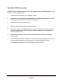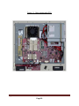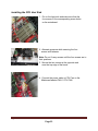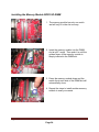
1
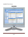
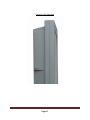
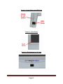
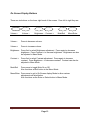
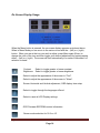
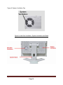
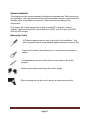
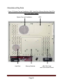
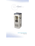
CyberMed H19 Series
User Guide
FCC-B Radio Frequency Interference Statement
This equipment has been tested and found to comply
with the limits for a class B digital device, pursuant to part 15 of the FCC rules. These
limits are designed to provide reasonable protection against harmful interference in a
residential installation. This equipment generates, uses and can radiate radio
frequency energy and, if not installed and used in accordance with the instruction
manual, may cause harmful interference to radio communications. However, there is
no guarantee that interference will not occur in a particular installation. If this
equipment does cause harmful interference to radio or television reception, which can
be determined by turning the equipment off and on, the user is encouraged to try to
correct the interference by one or more of the measures listed below.
• Reorient or relocate the receiving antenna.
• Increase the distance between the equipment and receiver.
• Connect the equipment into an outlet on a circuit different from that to which the
receiver is connected.
• Consult the dealer or an experienced radio/television technician for help.
Notice 1
The changes or modifications not expressly approved by the party
responsible for compliance could void the user's authority to operate the
equipment.
Notice 2
Shielded interface cables and A.C. power cord, if any, must be used in
order to comply with the emission limits.
Trademarks
All trademarks are the properties of their respective owners.
Intel® is a registered trademarks of Intel Corporation.
PS/2 and OS®/2 are registered trademarks of International Business Machines
Corporation.
Windows® 7/Vista/XP/NT/2000/98/95 are registered trademarks of Microsoft
Corporation.
Netware® is a registered trademark of Novell, Inc.
Award® is a registered trademark of Phoenix Technologies Ltd.
AMI® is a registered trademark of American Megatrends Inc
i
Safety Instructions
1.
2.
3.
4.
5.
6.
7.
8.
9.
10.
11.
12.
13.
14.
15.
Always read the safety instructions carefully.
Keep this equipment away from humidity.
Lay this equipment on a reliable flat surface before setting it up.
The openings on the enclosure are for air convection hence protect the
equipment from overheating. DO NOT COVER THE OPENINGS.
Confirm the voltage of the power source and adjust accordingly to 110/220V
before connecting the equipment to the power inlet.
Place the power cord in such a way that it cannot be stepped on. Do not
place anything over the power cord.
Always unplug the Power Cord before inserting any add-on card or module.
All cautions and warnings on the equipment should be noted.
Never pour any liquid into the opening. This will cause damage and/or electrical
shock.
Do not disable the protective grounding pin from the plug. The equipment must
be connected to a grounded main socket/outlet.
The Optical Storage devices are classified as Class 1 Laser products. Use of
controls or adjustments or performance of procedures other than those specified
is prohibited.
Do not touch the Laser lens inside the optical storage drive.
When installing the coaxial cable to the TV Tuner, it is necessary to ensure that
the metal shield is reliably connected to a protective earthing system of the
building. Cable distribution systems should be grounded (earthed) in accordance
with ANSI/NF PA 70, the National Electrical Code (NEC ), in particular, Section
820.93, Grounding of Outer Conductive Shield of a Coaxial Cable.
If any of the following situations arise, have the equipment checked by
authorized service personnel:
• The power cord or plug is damaged.
• Liquid has penetrated into the equipment.
• The equipment has been exposed to moisture.
• The equipment has not worked well or you cannot get it working according to
the User's Guide.
• The equipment has been dropped and damaged.
• The equipment has obvious signs of breakage.
Do not attempt to remove or upgrade any components by yourself, any
installation or modification should be conducted by service personnel.
DO NOT LEAVE THIS EQUIPMENT IN AN UNCONDITIONED ENVIRONMENT WITH
A STORAGE TEMPERATURE ABOVE 50° C (122°F). IT MAY DAMAGE THE
EQUIPMENT.
CAUTION: Danger of explosion if battery is incorrectly replaced. Replace only with the
same or equivalent type recommended by the manufacturer.
ii
WEEE Statement
(Waste Electrical and Electronic Equipment)
The WEEE directive places an obligation on EU-based manufacturers, distributors,
retailers and importers to take-back electronics products at the end of their useful life.
A sister Directive, ROHS (Restriction of Hazardous Substances) compliments the
WEEE Directive by banning the presence of specific hazardous substances in the
products at the design phase. The WEEE Directive covers products imported into the
EU as of August 13, 2005. EU-based manufacturers, distributors, retailers and
importers are obliged to finance the costs of recovery from municipal collection points,
reuse, and recycling of specified percentages per the WEEE requirements.
Instructions for disposal of WEEE by Users in the European Union
The symbol shown below is on the product or on its packaging, which indicates that
this product must not be disposed of with other waste. Instead, it is the user’s
responsibility to dispose of their waste equipment by handing it over to a designated
collection point for the recycling of waste electrical and electronic equipment. The
separate collection and recycling of your waste equipment at the time of disposal will
help to conserve natural resources and ensure that it is recycled in a manner that
protects human health and the environment. For more information about where you
can drop off your waste equipment for recycling, please contact your local city office,
your household waste disposal service or where you purchased the product.
iii
TABLE OF CONTENTS
FCC-B Radio Frequency Interference Statement ........................................................ i Trademarks ..................................................................................................................... i Safety Instructions ........................................................................................................ ii WEEE Statement .......................................................................................................... iii Introduction ................................................................................................................... 1 CyberMed H19 Series Specifications .......................................................................... 1 Processor Support .................................................................................................................. 1 Chipset..................................................................................................................................... .1 Memory Support ...................................................................................................................... 1 Networking ............................................................................................................................... 1 Audio......................................................................................................................................... 1 Hard Disk Drive ........................................................................................................................ 2 Mounting................................................................................................................................... 2 Swivel Stand............................................................................................................................. 2 LCD Panel ................................................................................................................................. 2 Expansion Slots ....................................................................................................................... 2 Front Lower Right Bezel ......................................................................................................... 2 Right Side Bezel....................................................................................................................... 2 Left Side Bezel ......................................................................................................................... 2 Bottom I/O Panel ..................................................................................................................... 2 Power Supply ........................................................................................................................... 2 Dimensions .............................................................................................................................. 2 Power Management....................................................................................................... 7 Waking the System Up ............................................................................................................ 9 Energy Saving Tips ................................................................................................................. 9 CyberMed H19 Series Overview ................................................................................. 10 On Screen Display Buttons .................................................................................................. 13 On Screen Display Usage ..................................................................................................... 14 System Assembly........................................................................................................ 17 Necessary Tools .................................................................................................................... 17 Orientation of Key Parts........................................................................................................ 18 CyberMed H19 Disassembly ................................................................................................. 19 Installing the CPU .................................................................................................................. 22 iv
Installing the CPU Heat Sink................................................................................................. 23 Installing the Memory Module DDR3 SO-DIMM .................................................................. 24 Installing the Hard Disk Drive ............................................................................................... 25 Installing the Mini-PCIe Card (Optional) .............................................................................. 26 Installing the Cover ............................................................................................................... 27 Cybernet E-Recycling SOP……………………………………….………………………………29
Figures
Figure 1: Front View ................................................................................................... 10 Figure 2: Left side view .............................................................................................. 11 Figure 3: Power Button and USB Ports ..................................................................... 12 Figure 4: Touch Panel ................................................................................................. 12 Figure 5: IrDA Receiver for TV Tuner ........................................................................ 12 Figure 6: Back view ..................................................................................................... 15 Figure 7: Bottom Panel I/O Ports ............................................................................... 15 Figure 8: System Ventilation Fan ............................................................................... 16 Figure 9: Heat Sink Ventilation, System Ventilation and Stand .............................. 16 Figure 10: ..................................................................................................................... 18 System Fan and Ventilation ............................................................................. 18 HDD ................................................................................................................... 18 Heat Sink, Memory Modules, Mini-PCIe and Touch Panel Control. ............. 18 Figure 11: Open system with GPU ........................................................................... 20 Figure 12: Open system without GPU ...................................................................... 21 v
Introduction
Congratulations for purchasing the CyberMed H19. The CyberMed H19 Series is your
best Slim LCD PC choice. With the fantastic appearance and small form factor, it can
easily be set anywhere. The feature packed platform also gives you an exciting PC
experience.
CyberMed H19 Series Specifications
Processor Support
The 2nd generation Intel® Core™ i3, i5 and Core™ i7 in the 1155 package up to 65W.
Motherboard Core Logic
Intel® H61 Express chipset (Sandy Bridge)
Memory Support
DDR3 1066/1333 MHz SO-DIMM SDRAM (Un-buffered Non-ECC)
2 DDR3 1333 MHz SO-DIMM slots (8GB Max)
Video & Graphics for H19
Intel® integrated H61 Chipset with Intel® HD Graphics
Intel GMA HD/Intel Clear Video HD Technology
Built-in support for 1080p HD video playback, HDMI 1.4 & Blu-ray 3D support
Supports Microsoft® DirectX 10.1, Shader Model 4.0 and OpenGL 3.0.
DVMT allocated as needed from 128MB to 1.70GB
Maximum display resolution 2560 x 1600.
Video & Graphics for H19G
Onboard NVIDIA GeForce GT 540M(630M) GPU
1.0GB sDDR3 128-bit RAM
1080p HD video playback, HDMI 1.4 & Blu-ray 3D support.
Supports Microsoft® DirectX 11, Shader Model 5.0 and OpenGL 4.1
Maximum display resolution 2560 x 1600.
Networking
Supports 2 PCI Express LAN 10/100/1000 Fast Ethernet by Realtek RTL8111E
Audio
2 internal speakers with 78dB+/-3dB @ 3W, 1 mic
HD Audio Codec Realtek® ALC892
Flexible 10-channel audio with jack sensing
Compliant with Azalia 1.0 Spec
CyberMed H19
Product Orientation
Page 1
Hard Disk Drive
One 3.5” SATA Hard Disk Drive - Any Capacity
Wall Mount
Support 75x75 / 100x100 VESA mounting hole.
Swivel Stand
System Base enables left/right rotation up to 60 degrees. Tilt from -5 to 60 degrees
LCD Panel
19" TFT LCD/LED panel screen 4:3 format display.
Expansion Slots
2 mini-PCIe (One full size and one half size)
Front Lower Right Bezel
On Screen Display Buttons
Volume Adjust
Brightness Adjust
Contrast Adjust
Mute/Exit
Menu/Enter
Right Side Bezel
1 power button
2 USB 2.0 ports (for mouse and keyboard)
Left Side Bezel
1 optical disk drive – 2.5” slim
Bottom I/O Panel
1 DC/IN port, 1 Serial port, 1 DVI-I port, 1 HDMI port, 2 LAN RJ-45 jack, 2 USB 3.0
ports, 2 USB 2.0 ports, 1 LPT port (Optional), 3 Audio jacks – Line in, Line Out and Mic
4 TV Tuner ports - - Optional with TV Tuner (COAX Cable In, RCA Composite Video In,
Audio Left & Audio Right), 1 CMOS clear button, 1 Reset button
Power Supply
135 Watt Power Adapter, AC Input: 100~240V ~, 1.6-0.8A, 47-63Hz.
DC Output: 135W MAX, 18-19V, 7.5A only
Dimensions
47.5cm (H) x 43cm (W) x 25.5cm (D) (with stand)
CyberMed H19
Product Orientation
Page 2
Intended use
The CyberMed H19 Series is intended to serve as a medical monitor which is designed
for general purpose for hospital environment and for diagnosis. It could be used for
Radiology, PACS (Picture Archiving Communication Systems), LIS (Lab Information
Systems) and Electronic Medical Record purpose. It shall not be used for life-supporting
system.
WARNING: Critical diagnostic decision must not be based solely on images displayed
by this device.
Unpacking
After opening the carton, there is a medical LCD PC with an accessory box. Check
carefully to see if there are any damages or missing parts.
Read the Manual
Please read this manual carefully and remember to keep this manual for future
reference.
Safety Instructions & Cleaning
This product has undergone various tests in order to comply with safety standards.
Inappropriate use or open the housing may be dangerous. Please remember to follow
the instructions below to ensure your safety during the installation and operating
process.
Transporting & Placement of unit
1. When moving the unit on a cart; be very cautious. Quick stops, excessive forces and
uneven surfaces may cause the cart to overturn thus risking the unit to fall to the
ground.
2. If the medical LCD PC unit does fall to the ground, immediately turn the power off and
disconnect cords. Then contact a service technician for repairs. Continual use of
the unit may result cause a fire or electric shock. Also, do not repair the unit on your
own.
3. Having two or more people transporting the medical LCD PC unit is recommended. In
addition, when installing the unit by suspending it also requires two or more people.
4. Before suspending the unit, make sure the material used for suspension is sturdy and
stable. If not properly suspended, the medical LCD PC unit may fall and cause serious
injury to people standing nearby as well as to the unit itself.
5. If the user wishes to mount the medical panel PC unit, remember to use only the
mounting hardware recommended by the manufacturer.
CyberMed H19
Product Orientation
Page 3
Electrical and Power Source Related
1. This medical LCD PC unit must operate on a power source as shown on the
specification label. If you are not sure what type of power supply used in the area,
consult your dealer or local power supplier.
2. The power cords must not be damaged. Applied pressure, added heat, and tugging
may damage the power cord.
3. The power cord must be routed properly when setup takes place. We advise that this
aspect measure is to prevent people from stepping on the cords or while the unit is
suspended to prevent flying objects from getting tangled with the unit.
4. Do not overload the AC outlets or extension cords. Electrical shocks or fires may
occur from overloading.
5. Do not touch the power source during a thunderstorm.
6. If your hands are wet, do not touch the plug.
7. Use your thumb and index finger, grip firmly on the power cord to disconnect from the
electrical socket. By pulling the power cord, may result in damaging it.
8. If the unit is not going to be in use for an extended period of time, remember to
disconnect the unit.
9. The medical LCD PC unit uses 19V DC output from an adapter. Connect the unit to a
power source with the same numerical value as indicated. Please use only the power
cord provided by the dealer to ensure safety and EMC compliance.
WARNING: To avoid risk of electric shock, this equipment must only be connected to a
supply mains with protective earth
Various Factors of Environment
1. Operating Temperature: 0°C to 50°C ; Non-operating temperature: 20°C to 60°C.
2. Operating Humidity (Non-Condensing): 10% to 90%. Non-operating Humidity (Noncondensing): 10% to 90%.
3.Do not insert objects into the openings.
4. Do not have liquids seep into the internal areas of the medical LCD PC unit.
5. Having liquids seep in or inserting objects into the unit may result in electric shocks
from taking and/or short circuiting the internal parts.
CyberMed H19
Product Orientation
Page 4
6. Do not place the medical LCD PC unit in the presence of high moisture areas.
7. Do not install the medical LCD PC unit in a wet environment.
8. Do not place unit near heat generating sources.
9. Do not place the unit in a location where it will come in contact with fumes or steam.
10. Remember to keep the medical LCD PC unit away from the presence of dust.
11. If water has flow in or seep in, immediately disconnect the open frame unit. Then
contact a service technician for repairs.
Ventilation Spacing
1. Do not cover or block the openings on the top and back sides of the medical LCD PC
unit. Inadequate ventilation may cause overheating thus reducing the lifespan of the
unit.
2. Unless proper ventilation is present, do not place unit in an enclosed area; such as a
built-in shelf. Keep a minimum distance of 10 cm between the medical LCD PC unit and
wall.
Cleaning the unit
1. Remember to turn off the power source and to unplug the cord from the outlet before
cleaning the unit.
2. Carefully dismount the unit or bring the unit down from suspension to clean.
3. Please use a dry soft cloth to clean the unit.
4. Take a dry cloth and wipe the unit dry. Remember to avoid having liquids seep into
the internal components and areas of the medical LCD PC unit.
Servicing, Repairing, Maintenance & Safety Checks
1. If the unit is not functioning properly, observe the performance level of the medical
LCD PC closely to determine what type of servicing is needed.
2. Do not attempt to repair the medical LCD PC unit on your own. Disassembling the
cover exposes users’ to high voltages and other dangerous conditions. Notify and
request a qualified service technician for servicing the unit.
3. To avoid risk of electric shock, this equipment must only be connected to a supply
mains with protective earth.
CyberMed H19
Product Orientation
Page 5
4. If any of the following situations occur turn the power source off and unplug the unit.
Then contact a qualified service technician.
(a) A liquid was spilled on the unit or objects have fallen into the unit.
(b) The unit is soaked with liquids.
(c) The unit is dropped or damaged.
(d) If smoke or strange odor is flowing out of the operating unit.
(e) If the power cord or plug is damaged.
(f) When the functions of the unit are dysfunctional.
5. When replacement parts are needed for the medical LCD PC unit, make sure service
technicians use replacement parts specified by the manufacturer, or those with the
same characteristics and performance as the original parts. If unauthorized parts are
used it may result in starting a fire, electrical shock and/or other dangers.
ISO 7000-0434: Caution, consult ACCOMPANYINGDOCUMENTS.
ISO 7000-1641: Follow operating instructions or Consult instructions
for use.
IEC 60417 -5009: ready to use.
IEC 60417-5031: Direct current.
EU-wide legislation, as implemented in each Member State, requires
that waste electrical and electronic products carrying the mark (left)
must be disposed of separately from normal household waste. This
includes monitors and electrical accessories, such as signal cables
or power cords. When you need to dispose of your medical panel PC
products, please follow the guidance of your local authority, or ask
the shop where you purchased the product, or if applicable, follow
any agreements made between yourself. The mark on electrical and
electronic products only applies to the current European Union
Member States.
CyberMed H19
Product Orientation
Page 6
Power Management
Power management of LCD-PC has the potential to save significant amounts of
electricity as well as deliver environment benefits.
To be energy efficient, turn off your display or set your LCD-PC to sleep mode after a
period of user inactivity.
Power Management in Windows OS
[Power Options] in Windows OS allow you to control the power management features of
your display and hard drive. Go to [Start] > [Control Panel].
Then click on the [Power Options] link.
CyberMed H19
Product Orientation
Page 7
Select a power plan that suits your personal needs. You may also fine-tune the settings
by clicking [Change plan settings].
The Shut Down LCD-PC Menu presents the options of Sleep (S3) & Shut Down (S5) for
rapid and easy management of your system power.
CyberMed H19
Product Orientation
Page 8
Power Management through ENERGY STAR qualified Monitors
(Optional)
The power management feature allows the LCD-PC to initiate a low-power or “Sleep”
mode after a period of user inactivity. When used with an external ENERGY STAR
qualified Monitor, this feature also supports similar power management features of the
monitor. To take advantage of these potential energy saving, the power management
feature can be set to behave in the following ways when the system is operating on AC
power:
• Turn off the display after 15 minutes.
• Initiate Sleep after 30 minutes.
Waking the System Up
The LCD-PC shall be able to wake up from power saving mode in response to a
command from any of the following:
• the power button,
• the network (Wake on LAN),
• the mouse
• the keyboard
Energy Saving Tips:
•
•
•
Tune the settings in Power Options under Windows OS to optimize your LCDPC’s power management.
Install power saving software to manage your PC’s energy consumption.
Always disconnect the AC power cord or switch the wall socket off if your LCDPC would be left unused for a certain time to achieve zero energy consumption.
CyberMed H19
Product Orientation
Page 9
CyberMed H19 Series Overview
Figure 1: Front View
CyberMed H19
Product Orientation
Page 10
Figure 2: Left side view
CyberMed H19
Product Orientation
Page 11
Figure 3: Power Button and USB Ports
Figure 4: Touch Panel
Figure 5: IrDA Receiver for TV Tuner
CyberMed H19
Product Orientation
Page 12
On Screen Display Buttons
There are six buttons on the lower right bezel of the screen. From left to right they are:
Volume –
Volume +
Brightness – Contrast +
Volume -
Press to decrease volume.
Volume +
Press to increase volume.
Mute/Exit
Menu/Enter
Brightness- Press first to select Brightness adjustment. Press again to decrease
brightness. Press Contrast + to increase brightness. Brightness can also
be adjusted in Menu Mode.
Contrast +
Press first to select Contrast adjustment. Press again to increase
contrast. Press Brightness – to decrease contrast. Contrast can also be
adjusted in Menu Mode.
Mute/Exit
Press once to toggle Mute On or Off.
Also functions as Exit button in the Menu Mode.
Menu/Enter Press once to get to On-Screen display Mode to allow various
adjustments as listed below.
Also functions as the Enter or Select button in Menu Mode.
CyberMed H19
Product Orientation
Page 13
On Screen Display Usage
When the Menu button is pressed, the on-screen display appears as pictured above.
When in Menu Mode you can move to the various icons with the – (left) or + (right)
button. When you are at the icon you wish to adjust, press Menu again (Enter) to
change the color of the icon and then toggle your desired adjustment by again pressing
either – (left) or + (right). The screen will exit automatically in a matter of seconds if no
selection is made.
Contrast
Brightness
Select to toggle greater or lesser contrast.
Select to toggle greater or lesser brightness.
Select to adjust the appearance of the screen to “Cool”.
Select to adjust the appearance of the screen to “Warm”.
Screen Horizontal and Vertical adjustment, OSD display time setup.
Select to toggle through the languages offered.
Select to reset all LCD Display settings
OSD Firmware EEPROM version information.
Screen mode selection for 16:9 or 4:3
CyberMed H19
Product Orientation
Page 14
Figure 6: Back view
Figure 7: Bottom Panel I/O Ports
CyberMed H19
Product Orientation
Page 15
Figure 8: System Ventilation Fan
Figure 9: Heat Sink Ventilation, System Ventilation and Stand
CyberMed H19
Product Orientation
Page 16
System Assembly
This chapter provides system assembly information and procedures. While performing
any installation, use a grounded wrist strap before handling computer components and
carefully follow all installation procedures. Static electricity may damage the
components.
This chapter will include instructions for how to install CPU, heat sink, memory
modules, hard disk drive (HDD), optical disk drive (ODD), mini-PCI card, mini-PCIE
card and IrDA module.
Necessary Tools
A Phillips screwdriver can be used to do most of the installation. One
with a magnetic head is recommended. Applied maximum torque is 5kg.
Pliers can be used as an auxiliary tool to connect some connectors or
cables.
Forceps/tweezers can be used to pick up tiny screws or set up the
jumpers.
Rubber gloves can prevent injury from static charge.
Electric screwdriver can be used to secure all screws more quickly.
CyberMed H19
Product Orientation
Page 17
Orientation of Key Parts
Figure 10:System Fan and Ventilation, HDD , Heat Sink, Memory Modules, Mini-PCIe
and Touch Panel Control.
System Fan and Ventilation
Heat Sink
Memory Modules
CyberMed H19
HDD
Mini-PCIe Card
and Touch Panel Control
Product Orientation
Page 18
CyberMed H19 Disassembly
ORIENTATION: Presumes the top of the iOne is away from you and the bottom or I/O
controller board is nearest you.
1.
Place the iOne face down on a padded surface.
2.
Remove the four screws from the base plate that attaches the stand to the LCD
supporting the base while removing the last screw.
3.
Remove the ten back bezel screws.
4.
Carefully remove the back bezel and set aside.
5.
Then remove the metal EMI shield by first removing the I/O cover by removing
the three screws on the bottom and two screws on the face. Lift the plate out
and up and set aside.
6.
Remove the remaining eleven screws around the metal shield covering the
motherboard.
7.
First lift the metal shield and slide it to the right clearing the optical drive door (at
the top right) then disconnect the system fan cable connector from the
motherboard at FAN2 next to the top right corner of the CPU.
CyberMed H19
Product Orientation
Page 19
Figure 11: Open system with GPU
CyberMed H19
Product Orientation
Page 20
Figure 12: Open system without GPU
CyberMed H19
Product Orientation
Page 21
Installing the CPU
NOTE: If you purchased your CyberMed H19 as a turn-key system, you must first
follow the instructions to remove the heat sink in order to be able to reach the CPU.
Systems purchased as ‘bare bones’ require the installation of the heat sink which is
shipped in the accessories box with the unit.
1. The socket has a plastic cap on it to protect
the pins from damage. This should remain
in place until actually installing a CPU.
2. Raise the plastic cap to reveal the socket
pins and open the cover by pushing down,
pulling out and up on the lever beside the
CPU socket.
Note: Do not touch the socket pins to avoid
damage.
3. Install the CPU after confirming the direction
for correct mating. Be sure to hold the CPU
by the edge of the CPU base.
Note: The CPU can only be installed in the correct
direction. Make sure the CPU pins are completely
embedded into the socket. If not, take out the CPU
with vertical motion and reinstall.
4. Close the cover and the lever to complete
installation. Replace the heat sink.
NOTE: Any violation of the correct installation procedures may cause permanent
damage to your mainboard.
CyberMed H19
Product Orientation
Page 22
Installing the CPU Heat Sink
1. Put on the heat sink and make sure that the
four screws fit the corresponding screw holes
on the mainboard.
2. Alternate pressure while securing the four
screws with balance.
Note: Do not fix any screws until the four screws are in
their positions.
3. Secure the two screws at the opposite end
near the top edge of the bezel.
4. Connect the power cable to CPU Fan on the
Mainboard labeled FAN 1 CPU FAN.
CyberMed H19
Product Orientation
Page 23
Installing the Memory Module DDR3 SO-DIMM
1. The memory module has only one notch
and will only fit in the slot one way.
2. Insert the memory module into the DIMM
slot at a 45° angle. Then push it in until the
golden finger on the memory module is
deeply inserted in the DIMM slot.
3. Press the memory module down and the
metal clip at each side of the DIMM slot will
automatically close.
4. Repeat the steps to install another memory
module to meet your needs.
CyberMed H19
Product Orientation
Page 24
Installing the Hard Disk Drive
1. Unscrew the four screws on the Optical
Disk
Drive frame (2 shown circled, 2 on opposite
side) and remove the frame and
disconnect the SATA cable from the
mainboard and set aside in order to gain
access to the Hard Disk Drive slot.
Optical Disk Drive Frame Screws
2. Slide the hard disk drive into the frame and
line up the two screw holes accordingly.
Secure the two screws on the Hard Disk
Drive.
Connect the SATA cable to the mainboard.
SATA Cable
3. Connect the other end of the SATA/Power
cable to the Hard Disk Drive as shown.
4. Replace the Optical Disk Drive securing
the four screws (two screws on the top, two
screws on the side) to secure the HDD and
complete the installation.
Power Cable
CyberMed H19
SATA Cable
Product Orientation
Page 25
Installing the Mini-PCIe Card (Optional)
1. The mini-PCIE card has only one
notch and will only fit in one way.
Insert the mini-PCIe card into the
mini-PCIe slot at a 45° angle.
Then push it in until the golden
finger on the mini-PCIe card is
deeply inserted in the mini-PCIe
slot.
2. Press down the mini-PCIe card
and secure the screw to complete
the installation.
CyberMed H19
Product Orientation
Page 26
Installing the Cover
1. Connect the power cable to System Fan on the
mainboard before securing the metal cover with
seventeen screws.
2. Secure the plastic cover with eleven screws.
3. Secure the stand with four screws.
CyberMed H19
Product Orientation
Page 27
CyberMed H19
Product Orientation
Page 28
Cybernet e-recycling SOP
Cybernet has an e-recycling program that is very easy to use. Just follow the steps
explained below or go to our website at www.cybernetman.com.
1. Request an RMA via phone, email or support request.
2. We will arrange a call tag to have the product picked up. Just have it packed and
ready to ship.
We do the rest!
CyberMed H19
Product Orientation
Page 29