1
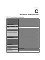
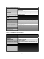
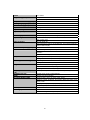
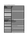
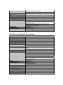
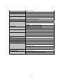
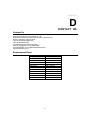
User’s Manual
Touch Screen Monitor
Model: TM-15"/17"/19"/22"W
Version 2.0 2010.10
Copyright 2010 Sinocan International Technologies Co.,Ltd. All Rights Reserved.
No part of this publication may be reproduced, transmitted, transcribed, stored in a
retrieval system, or translated into any language or computer language, in any form or by
any means, including, but not limited to, electronic, magnetic, optical, chemical, manual,
or otherwise without prior written permission of Sinocan International Technologies Co.,
Ltd.
Disclaimer
The information in this document is subject to change without notice. Sinocan company
makes no representations or warranties with respect to the contents hereof, and
specifically disclaims any implied warranties of merchantability or fitness for a particular
purpose. Sinocan International reserves the right to revise this publication and to make
changes from time to time in the content hereof without obligation of Sinocan
International Technologies Co., Ltd. to notify any person of such revisions or changes.
Trademark Acknowledgments
Sinocan is trademark. Other product names mentioned herein may be trademarks or
registered trademarks of their respective companies.
2
Warnings and Cautions Warning • Danger — Explosion hazard. Do not use in the presence of flammable anesthetics. • To prevent fire or shock hazards, do not immerse the unit in water or expose it to rain or moisture. • Do not use the unit with an extension cord receptacle or other outlets unless the prongs of the power cord can be fully inserted. • RISK OF ELECTRICAL SHOCK — DO NOT OPEN. To reduce the risk of electrical shock, DO NOT remove the back of the equipment or open the enclosure. No user‐serviceable parts are inside. Refer servicing to qualified field service engineers only. • Uninsulated voltage within the unit may have sufficient magnitude to cause electrical shock. Avoid contact with any part inside the unit. Caution • Before connecting the cables to your Elo TouchSystems touchmonitor, make sure all components are powered OFF. • The use of ACCESSORY equipment not complying with the equivalent safety requirements of this equipment may lead to a reduced safety of the resulting system. Consideration relating to the choices of accessory equipment should include: • Use of accessory in the patient vicinity. • Evidence that the safety certification of the accessory has been performed in accordance to the appropriate IEC 60601‐1 and/or IEC 60601‐1‐1 harmonized national standard. • For continued safety — ‐ This unit only complies to the above standards if used with a medical grade power cord. ‐ A medical grade power adaptor, such as the one specified, is required for use in a medical application. Note: • This symbol alerts the user to important information concerning the operation and maintenance of this unit, which should be read carefully to avoid problems. CAUTION‐Life Support Care must be taken when this touchmonitor is a critical component of a Life support system or device. In case of failure of this touchmonitor, appropriate redundant systems should be incorporated into the system or device to prevent injury to the user or patient. The following should be an integral part of the safety design of a Life support system or device using this touchmonitor for a critical function. ♦ An Alternate interface or fail‐safe must be available should the touchscreen fail to operate. ♦ The touchscreen interface must not be the only means of control of a critical function. ♦ An Alternate video monitor should be incorporated into the safety design if used 3
to monitor a critical function. ♦ The internal speakers of this touchmonitor must not be the sole method of warning of a critical function. Critical functions are: 1. Life support devices or systems are devices or systems which, (a) are intended for surgical implant into the body, or (b) support or sustain life, or (c) whose failure to perform when properly used in accordance with instructions for use provided in the labeling, can be reasonably expected to result in significant injury to the user. 2. A critical component is any component of a life support device or system whose failure to perform can be reasonably expected to cause the failure of the life support device or system, or to affect its safety or effectiveness. Table of Contents
INTRODUCTION ................................................................. ..................... ................... 7
4
Product Description ....................................................................................................... 7
LCD Monitor Performance Features ............................................................................. 7
TFT LCD Monitor Panel......................................................... .................................. 7
External Medical Grade Power Adaptor..................................................................... 7
INSTALLATION AND SETUP ......................................... ..... ..................................... 8
Unpacking Your Touchmonitor...................................................................................... 8
Product Overview .......................................................................................................... 8
Front View ........................................................................................ .........................9
Rear View ................................................................................................................ 10
Side View...................................................................................... ............................10
KensingtonTM Lock................................................................ .................................... 11
USB Interface Connection ........................................................................................... 11
Replace the Cable Cover............................................................................................... 13
Optimizing the LCD Monitor ...................................................................................... 14
Installing the Touch Driver Software .......................................................................... 14
Installing the USB Touch Driver ................................................................................. 15
Installing the USB Touch Driver for Windows XP... ............................ ................ 16
OPERATION............................................................................ ..................................... 17
About Touchmonitor Adjustments .............................................................................. 17
Controls and Adjustment ............................................................................................. 17
OSD Lock/Unlock ................................................................................................... 17
Power Lock/Unlock ................................................................................................. 18
OSD Menu Functions .............................................................................................. 18
OSD Control Options (Clockwise) .......................................................................... 18
Power LED Monitor & Power Saving.......................................................................... 18
General Power Saving Mode ................................................................................... 18
Monitor Angle (desktop only) ..................................................................................... 19
TROUBLESHOOTING..................................................... ........................................... 20
Solutions to Common Problems .................................................................................. 20
NATIVE RESOLUTION .............................................. .......... .................................... 21
TOUCHMONITOR SAFETY...................................... ................................................ 22
Care and Handling of Your Touchmonitor................................................................... 22
TECHNICAL SPECIFICATIONS............................ .................................................. 22
Touchmonitor Specifications ....................................................................................... 23
CONTACT US......................................................... ...................................................... 30
Contact Us.................................................................................................................... 30
Replacement Parts......................................................................................................... 30
WARRANTY ........................................... ........ ............................................................. 31
CHAPTER
5
1
INTRODUCTION
Product Description
The T06 series touch screen monitors which use liquid crystal monitor (LCD) technology,
designed to present information to the operator, care-giver and the patient. The T06 series
features both serial and USB touch interfaces as standard configuration. The T06 series
functionally consists of 15/17/17/22 inch LCD main monitor with a touch screen. The
monitors element is a 15.0 inch diagonal XGA resolution (1024x768) LCD monitor, 17
inch diagonal XGA resolution 1280x1024 LCD monitor, and 22 inch diagonal WXGA
resolution (1680x1050) wide screen LCD monitor.Three types of touchscreen technology
are offered for the T06 series as Resistive touch screen technology. The T06 series are
powered by 12V DC from an external industrial power adapter.
LCD Monitor Performance Features
15 inch TFT LCD Monitor Panel
Monitor format
Monitor area
Pixel pitch
Contrast ratio
Brightness LCD
Response time
Monitor color
Typical vertical viewing angle:
Typical horizontal viewing angle:
1024x768
304.1 mm (H) x 228 mm (V)
0.297 mm (H) x 0.297 mm (V
600:1 typical
250 cd/m2 (Typical)
14.2 msec typical
16.7 million colors, 6 Bit with dithering
85 deg (looking down) / 85 deg (looking up)
85 deg (looking left) / 85 deg (looking right)
17 inch TFT LCD Monitor Panel
Monitor format
Monitor area
Pixel pitch
Contrast ratio
Brightness LCD
Response time
Monitor color
Typical vertical viewing angle:
Typical horizontal viewing angle:
1280x1024
338 mm (H) x 270 mm (V)
0.264 mm (H) x 0.264 mm (V
1000:1 typical
250 cd/m2 (Typical)
5 msec typical
16.7 million colors, 6 Bit with dithering
80 deg (looking down) / 80 deg (looking up)
80 deg (looking left) / 80 deg (looking right)
19 inch TFT LCD Monitor Panel
Monitor format
1280x1024
6
Monitor area
Pixel pitch
Contrast ratio
Brightness LCD
Response time
Monitor color
Typical vertical viewing angle:
Typical horizontal viewing angle:
376 mm (H) x 301 mm (V)
0.294 mm (H) x 0.294 mm (V
1000:1 typical
250 cd/m2 (Typical)
5msec typical
16.7 million colors, 6 Bit with dithering
89 deg (looking down) / 89 deg (looking up)
89 deg (looking left) / 89 deg (looking right)
22 inch TFT LCD Monitor Panel
Monitor format
Monitor area
Pixel pitch
Contrast ratio
Brightness LCD
Response time
Monitor color
Typical vertical viewing angle:
Typical horizontal viewing angle:
1680x1050
473.7 mm (H) x 296.1 mm (V)
0.294 mm (H) x 0.294 mm (V
1000:1 typical
300 cd/m2 (Typical)
5 msec typical
16.7 million colors, 6 Bit with dithering
85 deg (looking down) / 80 deg (looking up)
85 deg (looking left) / 80 deg (looking right)
External Power Adapter
The T06 series is powered by an external input power adapter.
Power adapter:
·AC power: Input voltage 100 - 240 Vac
·Input frequency 50 / 60 Hz
·DC output: 12 V DC
·Line and load regulation: ± 3 %
CHAPTER
7
2
INSTALLATION AND SETUP
This chapter discusses how to install your LCD touchmonitor and how to install touch
screen driver software.
Unpacking Your Touchmonitor
Check that the following items are present and in good condition:
Product Overview
8
Front View
T06‐15 T06‐17 T06‐19 T06‐22W Rear View
9
Side View
Kensington™ Lock
10
The Kensington™ lock is a security device that prevents theft. To find out more about
this security device, go to http://www.kensington.com.
USB Interface Connection
Your touchmonitor comes with one USB cable. (For use with Windows 2000, ME, and
XP, 7 systems only.)
To set up the monitor, please refer to the following figures and procedures:
Install the Stand Base
The cables are connected at the back of the monitor.
CAUTION Before connecting the cables to your touchmonitor and PC, be sure that the computer and
touchmonitor are turned off.
To install the stand bottom plate.
NOTE Before connecting the cables to the touchmonitor, route all the cables that you will be using through
the hole in the base as shown in the picture above. Only use one of the following: Serial or USB touch cable
and VGA video cable.
11
The following illustrations guide you step by step in connecting your touchmonitor using
a Serial or USB cable connection with VGA video cable..
Connect one end of the VGA cable to the rear side of computer and the other to the
LCD. Tighten by turning the two thumb screws clockwise to ensure proper grounding.
You can select VGA video cable shown respectively.
Connect one end of the speaker cable to the speaker port in the computer and the other
end to the port in the monitor. (If your order needs built-in two speakers)
or
Connect one end of the Serial or USB cable to the rear side of the computer and the other
to the LCD monitor, shown respectively.
or Connect the cylindrical connecter from the power adaptor to the monitor. Connect the
appropriate power cord to the power adaptor and to the appropriate power outlet.
Connect Cables
12
After you have attached all the cables to the monitor; gently bring all the cables toward
the center so they fit under the cable cover lip. Snap the cable cover in place over the
connections.
Optimizing the LCD Monitor
To ensure the LCD monitor works well with your computer, configure the monitor mode
of your graphic card to make it less than or equal to default resolution, and make sure
the timing of the monitor mode is compatible with the LCD monitor. Refer to Appendix
A for more information about resolution. Compatible video modes for your touchmonitor
are listed in Appendix C.
Installing the Touch Driver Software
Driver software that allows your touchmonitor to work with
your computer comes with the TouchSystems monitor. Drivers are located on the
enclosed TouchTools CD-ROM for the following operating
systems:
• Windows XP
• Windows 2000
• Windows Me
• Windows 98
• Windows 95
• Windows NT 4.0
• CE 2.x, 3.0, 4x
• Windows XP Embedded
• Windows 3.x
• MS DOS
• iMAC
Additional drivers and driver information for other operating systems (including
Macintosh and Linux) are available on our Touch Systems web site at www.lcdpc.com.cn.
Your USB touchmonitor is “plug-and- play” compliant. Information on the video
13
capabilities of your touchmonitor is sent to your video monitor adapter when Windows
starts. If Windows detects your touchmonitor, follow the instructions on the screen to
install a generic plug-and-play monitor. Refer to the appropriate section below for driver
installation instructions.
Installing the USB Touch Driver
Installing the USB Touch Driver for Windows 7, Windows XP
Insert the Touch Drivers CD-ROM in your computer’s CD-ROM drive.
If Windows XP, starts the Add New Hardware Wizard, then:
1. Choose Next. Select “Search for the best driver for your device (Recommended)”
and choose Next.
2. When a list of search locations is monitored, place a checkmark on “Specify a
location” and use Browse to select the directory on the Touch Drivers CD-ROM.
3. Choose Next. Once the Touch Drivers USB touchscreen driver has been detected,
choose Next again.
4. You will see several files being copied. Insert your Windows OS CD if prompted.
Choose Finish.
If Windows 7, XP, Windows 2000, Windows 98, or Windows Me does not start the
Add New Hardware Wizard:
NOTE: For Windows 7 and Windows XP/2000, you must have administrator
access rights to install the driver.
1. If the AutoStart feature for your CD-ROM drive is active, the system automatically
detects the CD and starts the setup program.
2. Follow the directions on the screen to complete the driver setup for your version of
Windows.
If the AutoStart feature is not active:
1. Click Start > Run.
2. Click the Browse button to locate the autorun.exe program on the CDROM.
3. Click Open, then OK to run autorun.exe
4. Follow the directions on the screen to complete the driver setup for your version
of Windows. For T06 series you have to select Resistive Touch button.
14
Installing the Serial Touch Driver
Installing the Serial Touch Driver for Windows 7, Windows XP/2000
1. Insert the Touch Drivers CD-ROM in your computer’s CD-ROM drive. please ope n
the folder your \\CD-ROM\Resistive Touch Drivers\Serial\Driver
2. Select the drivers folder to complete the driver setup for your version of Windows.
15
CHAPTER
3
OPERATION
About Touchmonitor Adjustments
Your touchmonitor will unlikely require adjustment. Variations in video output and
application may require adjustments to your touchmonitor to optimize the quality of the
display.
For best performance, your touchmonitor should be operating in native resolution, that is
1024x768 for T06-15, 1280x1024 for T06-17/19, 1680x1050 for T06-22W at 60-75 Hz.
Use the Display control panel in Windows to choose standard resolution. Operating in
other resolutions will degrade video performance. For further information, please refer to
Appendix A. All adjustments you make to the controls are automatically memorized.
This feature saves you from having to reset the choices every time the power is
unplugged or the touchmonitor is turned off and on. If there is a power failure, your
touchmonitor settings will not default to the factory specifications.
To restore factory set up, choose it from the OSD. See page 3-25
.
16
Table 1 - User controls
#
Control
1
2
+
3
4
AUTO
5
POWER
Function
Menu monitor and menu exit
Adjusts the increasing value of the selected OSD control option.
Adjusts the decreasing value of the selected OSD control option
Auto-Adjust
Auto-Adjust
Controls and Adjustment
OSD Menu Functions
To monitor the OSD Menu, press
the button.
1 Press the + button or the - button to select the different OSD control option.
2 When the function you want to change is monitored, press the
button.
To adjust the Value of the function:
1 Press the + button to increase the value of the selected OSD control option.
2 Press the - button to decrease the value of the selected OSD control option.
After adjusting the values, the monitor will automatically save the changes.
NOTE: The OSD screen will disappear if no input activities are detected for 45 seconds.
OSD Control Options (Clockwise)
Contrast
• Adjusts the contrast or the values of color gain (RED, GREEN or BLUE).
Brightness
• Background luminance of the LCD panel is adjusted.
Vertical Position
• Adjusts vertical position of image.
Horizontal Position
• Adjusts horizontal position of image.
Recall Defaults
17
• Recalls the factory OSD default settings.
RGB - Color Temperature
• Select preset color temperature of 9300°K, 6500°K, 5500°K, 7500°K or select USER to
customize Red, Green and Blue gain.
Audio
• Adjust audio volume of speakers internal to the 1528L monitor.
Sharpness
• Adjust image sharpness.
Phase
• Adjusts the phase of the dot clock. Adjust for best image.
Clock
• Adjusts the ratio of dividing frequency of the dot clock. Adjust to remove vertical dark
bands in image.
OSD Left/Right
• The OSD screen is moved vertically right and left.
OSD Up/Down
• The OSD screen is moved vertically up and down.
OSD Timeout
• Adjusts the amount of time in which the OSD will disappear (45 to 255 seconds).
Auto Adjust
• Horizontal and vertical frequencies are monitored. Press select to automatically adjust
image (under 5 seconds).
Language
• Selects the languages used for OSD menu monitor.
Input Select
• Use to select analog or digital input.
Power LED Monitor & Power Saving
General Power Saving Mode
When the power is on and video is present, this LED lights in green.
The LED indicates the different power status with altered LED colors when monitor
operates in different modes (see following table).
Table 2 - Power Saving Indicator
Mode
On
Sleep
Off
Power Consumption
30 w max
6 w max
5w
Indicator
Green
Orange
NO
Note: If the monitor is not to be used for an extended period of time, it is recommended
that the monitor be turned off.
Monitor Angle (desktop only)
For viewing clarity, you can tilt the LCD forward or back for the best viewing angle and
18
minimum glare.
CAUTION ·In order to protect the LCD, be sure to hold the base when adjusting the LCD. ·For models without a touchscreen take care not to touch the screen. 19
CHAPTER
4
TROUBLESHOOTING
If you are experiencing trouble with your touchmonitor, refer to the following table. If the
problem persists, please contact your local dealer or our service center.Sinocan Technical
Support numbers are listed on page 28. Solutions to Common Problems
Problem
Suggestion(s)
The monitor does not respond
• Check that the monitor’s Power Switch is on.
• Turn off the power and check the monitor’s power cord
and signal cable for proper connection.
• Refer to the Controls and Adjustments section to adjust
the brightness.
• During operation, the monitor screen may automatically
turn off as a result of the Power Saving feature. Press any
key to see if the screen reappears.
• Refer to the Controls and Adjustments section to adjust
the brightness.
• Check to see of the resolution or vertical frequency of
your computer is higher than that of the LCD monitor.
• Reconfigure the resolution of your computer to make it
less than or equal to 1024x768. 1024x768 is optimal. See
Appendix A for more information on resolution.
• Make sure cable is securely attached at both ends.
Characters on the screen are dim
The screen is blank
“Out of Range” monitor
Touch doesn’t work
20
APPENDIX
A
NATIVE RESOLUTION
The native resolution of a monitor is the resolution level at which the LCD panel is
designed to perform best. For the TouchSystems LCD touchmonitor, the native resolution
is 1024 x 768 for the 15.0 inch size, 1280x1024 for the 17/19 inch size, and 1680x1050
for the 22 inch size. In almost all cases, screen images look best when viewed at their
native resolution. You can lower the resolution setting of a monitor but not increase it.
For exmple:
Input Video
15.0" LCD
640x480 (VGA)
800x600 (SVGA)
1024x768(XGA)
Transforms input format to 1024x768
Transforms input format to 1024x768
Monitor in Native Resolution
The native resolution of an LCD is the actual number of pixels horizontally in the LCD
by the number of pixels vertically in the LCD. LCD resolution is usually represented by
the following symbols:
VGA
SVGA
XGA
640x480
800x600
1024x768
As an example, a SVGA resolution LCD panel has 800 pixels horizontally by 600 pixels
vertically. Input video is also represented by the same terms. XGA input video has a
format of 1024 pixels horizontally by 768 pixels vertically. When the input pixels
contained in the video input format match the native resolution of the panel, there is a one
to one correspondence of mapping of input video pixels to LCD pixels. As an example,
the pixel in column 45 and row 26 of the input video is in column 45 and row 26 of the
LCD. For the case when the input video is at a lower or higher resolution than the native
resolution of the LCD, the direct correspondence between the video pixels and the LCD
pixels is lost. The LCD controller can compute the correspondence between video pixels
and LCD pixels using algorithms contained on its controller. The accuracy of the
algorithms determines the fidelity of conversion of video pixels to LCD pixels. Poor
fidelity conversion can result in artifacts in the LCD displayed image such as varying
width characters.
21
APPENDIX
B
TOUCHMONITOR SAFETY
This manual contains information that is important for the proper setup and maintenance
of your touchmonitor. Before setting up and powering on your new touchmonitor, read
through this manual, especially Chapter 2 (Installation), and Chapter 3 (Operation).
1. To reduce the risk of electric shock, follow all safety notices and never
open the touchmonitor case.
2. Turn off the product before cleaning. (See page 19 for Cleaning
Instructions.)
3. Your touchmonitor is equipped with a 3-wire, grounding power cord. The
power cord plug will only fit into a grounded outlet. Do not attempt to fit
the plug into an outlet that has not been configured for this purpose. Do not
use a damaged power cord. Use only the power cord that comes with your
Touch touchmonitor. Use of an unauthorized power cord may invalidate
your warranty.
4. The slots located on the sides and top of the touchmonitor case are for
ventilation. Do not block or insert anything inside the ventilation slots.
5. It is important that your touchmonitor remains dry. Do not pour liquid into
or onto your touchmonitor. If your touchmonitor becomes wet do not
attempt to repair it yourself.
Care and Handling of Your Touch Monitor
The following tips will help keep your touchmonitor functioning at the optimal level.
· To avoid risk of electric shock, do not disassemble the power adaptor or
monitor cabinet. The monitor is not user serviceable. Remember to unplug the
monitor from the power outlet before cleaning.
· Do not use alcohol (methyl, ethyl or isopropyl) or any strong dissolvent on the
monitor. Do not use thinner or benzene, abrasive cleaners or compressed air
on the monitor.
· To clean the monitor cabinet, use a soft cloth lightly dampened with a mild
detergent.
· Avoid getting liquids inside your touchmonitor. If liquid does get inside, have a
qualified service technician check it before you power it on again.
· Do not wipe the screen with a cloth or sponge that could scratch the surface.
22
· To clean the touchscreen, use window or glass cleaner. Put the cleaner on a soft
cloth and wipe the touchscreen. Never apply the cleaner directly on the
touchscreen.
23
APPENDIX
C
TECHNICAL SPECIFICATION
T06-15 Touch Monitor Specification
Model
Form factor
Enclosure color
Diagonal size
Aspect ratio
Useful screen area
Monitor
stand)
dimensions
(with
Native (optimal) resolution
Other supported resolutions
Colors
Brightness(typical)
Response time - total (typical)
Viewing angle (typical)
Contrast ratio (typical)
Input video format
Input video signal connector
Input frequency
Power supply
Input voltage
Input connector
T06-15
Desktop
Black
15.0"
4:3
Horizontal: 12.0" (304 mm)
Vertical: 9.0" (228 mm)
Width: 13.8" (350 mm) Height: 12.2" (310 mm) Depth: 6.9"
(175 mm)
Dimensions vary with stand position and options selected
1024 x 768 @ 60 Hz
1024 x 768 @ 60, 65 Hz (Sun), 70 or 75 Hz
832 x 624 @ 75 Hz (Mac)
800 x 600 @ 56, 60, 72 or 75 Hz
720 x 400 @ 0 Hz
640 x 480 @ 60, 66 Hz (Mac), 72 or 75 Hz
640 x 350 @ 70 Hz
16.7 million
LCD panel: 250 nits
ResistiveTouch: 200 nits
14.2 msec
Horizontal: ±70° or 140° total
500:1
Analog VGA
D-Sub 15-Pin VGA type
Horizontal: 31.5-60.2 kHz
Vertical: 56.3-75 Hz
Internal AC, Optional external DC (power brick)
AC: 100-240 VAC, 50/60 Hz
DC: +12VDC ±5%
AC: IEC 60320 C6
DC: Coaxial power jack (2 mm pin diameter, 6.4 mm barrel
diameter, 8.8 mm barrel length)
24
Power consumption (typical)
Options
Temperature
Humidity(noncondensing)
Weight
Shipping box dimensions(W x
D x H)
Backlight lamp life
MTBF
On-screen display (OSD)
Stand options
Mounting options
30 W
3-Tracks Magnetic Stripe Reader, USB interface
VFD Customer Display, 2 lines with 20 characters per line,
Serial interface
Wall mount or celling mount brackets
Operating: 0°C to 40°C (32°F to 104°F)
Storage: -20°C to 60°C (-4°F to 140°F)
Operating: 20%-80%
Storage: 10%-90%
Actual with stand: 10.6 lb (4.8 kg)
Actual without stand: 7.3 lb (3.3 kg)
Shipping with stand: 15.4 lb (7.0 kg)
16.54" (420 mm) x 14.96" (380 mm) x 10.24" (260 mm)
Typical 30,000 hours to half brightness
50,000 hours demonstrated
Controls (side): menu, up, down, select, power
Settings: contrast, brightness, H/V position, RGB (color temp),
clock, phase, recall
Languages: English, German, Spanish, Japanese, French
Lockouts: power, user controls
Removable
75 mm VESA mount
Threaded-through mounting holes, under stand
T06-17 Touch Monitor Specification
Model
T06-17
Form factor
Desktop
Enclosure color
Black
Diagonal size
17.0"
Aspect ratio
4:3
Useful screen area
Horizontal: 12.0" (304 mm)
Vertical: 9.0" (228 mm)
Monitor dimensions (with stand)
Width: 13.8" (350 mm) Height: 12.2" (310 mm) Depth: 6.9" (175
mm)
Dimensions vary with stand position and options selected
Native (optimal) resolution
1280 x 1024 @ 85 Hz
Other supported resolutions
1024 x 768 @ 60, 65 Hz (Sun), 70 or 75 Hz
832 x 624 @ 75 Hz (Mac)
800 x 600 @ 56, 60, 72 or 75 Hz
720 x 400 @ 0 Hz
640 x 480 @ 60, 66 Hz (Mac), 72 or 75 Hz
640 x 350 @ 70 Hz
25
Colors
16.7 million
Brightness(typical)
LCD panel: 250 nits
ResistiveTouch: 200 nits
Response time - total (typical)
5 msec
Viewing angle (typical)
Horizontal: ±80° or 160° total
Contrast ratio (typical)
1000:1
Input video format
Analog VGA
Input video signal connector
D-Sub 15-Pin VGA type
Input frequency
Horizontal: 31.5-60.2 kHz
Vertical: 56.3-75 Hz
Power supply
Internal AC, Optional external DC (power brick)
Input voltage
AC: 100-240 VAC, 50/60 Hz
DC: +12VDC ±5%
Input connector
AC: IEC 60320 C6
Power consumption (typical)
DC: Coaxial power jack (2 mm pin diameter, 6.4 mm barrel diameter,
8.8 mm barrel length)
35 W
Options
3-Tracks Magnetic Stripe Reader, USB interface
VFD Customer Display, 2 lines with 20 characters per line, Serial
interface
Wall mount or celling mount brackets
Temperature
Operating: 0°C to 40°C (32°F to 104°F)
Storage: -20°C to 60°C (-4°F to 140°F)
Humidity(noncondensing)
Operating: 20%-80%
Storage: 10%-90%
Weight
Actual with stand: 10.6 lb (4.8 kg)
Actual without stand: 7.3 lb (3.3 kg)
Shipping with stand: 15.4 lb (7.0 kg)
Shipping box dimensions(W x D
x H)
Backlight lamp life
16.54" (420 mm) x 14.96" (380 mm) x 10.24" (260 mm)
MTBF
50,000 hours demonstrated
On-screen display (OSD)
Controls (side): menu, up, down, select, power
Typical 30,000 hours to half brightness
Settings: contrast, brightness, H/V position, RGB (color temp), clock,
phase, recall
Languages: English, German, Spanish, Japanese, French
Lockouts: power, user controls
Stand options
Removable
Mounting options
75 mm VESA mount
Threaded-through mounting holes, under stand
26
T06-19 Touch Monitor Specification
Model
T06-19
Form factor
Desktop
Enclosure color
Black
Diagonal size
19.0"
Aspect ratio
4:03
Useful screen area
Horizontal: 12.0" (304 mm)
Vertical: 9.0" (228 mm)
Monitor dimensions (with stand)
Width: 13.8" (350 mm) Height: 12.2" (310 mm) Depth: 6.9" (175
mm)
Dimensions vary with stand position and options selected
Native (optimal) resolution
1280 x 1024 @ 85 Hz
Other supported resolutions
1024 x 768 @ 60, 65 Hz (Sun), 70 or 75 Hz
832 x 624 @ 75 Hz (Mac)
800 x 600 @ 56, 60, 72 or 75 Hz
720 x 400 @ 0 Hz
640 x 480 @ 60, 66 Hz (Mac), 72 or 75 Hz
640 x 350 @ 70 Hz
Colors
16.7 million
Brightness(typical)
LCD panel: 250 nits
ResistiveTouch: 200 nits
Response time - total (typical)
5 msec
Viewing angle (typical)
Horizontal: ±80° or 160° total
Contrast ratio (typical)
1000:01:00
Input video format
Analog VGA
Input video signal connector
D-Sub 15-Pin VGA type
Input frequency
Horizontal: 31.5-60.2 kHz
Vertical: 56.3-75 Hz
Power supply
Internal AC, Optional external DC (power brick)
Input voltage
AC: 100-240 VAC, 50/60 Hz
DC: +12VDC ±5%
Input connector
AC: IEC 60320 C6
Power consumption (typical)
DC: Coaxial power jack (2 mm pin diameter, 6.4 mm barrel
diameter, 8.8 mm barrel length)
40 W
Options
3-Tracks Magnetic Stripe Reader, USB interface
VFD Customer Display, 2 lines with 20 characters per line, Serial
interface
Wall mount or celling mount brackets
Temperature
Operating: 0°C to 40°C (32°F to 104°F)
Storage: -20°C to 60°C (-4°F to 140°F)
Humidity(noncondensing)
Operating: 20%-80%
Storage: 10%-90%
Weight
Actual with stand: 10.6 lb (4.8 kg)
27
Actual without stand: 7.3 lb (3.3 kg)
Shipping with stand: 15.4 lb (7.0 kg)
Shipping box dimensions(W x D
x H)
Optional product coverage
16.54" (420 mm) x 14.96" (380 mm) x 10.24" (260 mm)
Backlight lamp life
Typical 30,000 hours to half brightness
MTBF
50,000 hours demonstrated
On-screen display (OSD)
Controls (side): menu, up, down, select, power
Advance Unit Replacement program (North America only)
Settings: contrast, brightness, H/V position, RGB (color temp),
clock, phase, recall
Languages: English, German, Spanish, Japanese, French
Lockouts: power, user controls
Stand options
Removable
Mounting options
75 mm VESA mount
Threaded-through mounting holes, under stand
T06-22W Touch Monitor Specification
Model
T06-22W
Form factor
Desktop
Enclosure color
Black
Diagonal size
22"
Aspect ratio
16:10
Useful screen area
Horizontal: 12.0" (304 mm)
Vertical: 9.0" (228 mm)
Monitor dimensions (with stand)
Width: 13.8" (350 mm) Height: 12.2" (310 mm) Depth: 6.9" (175
mm)
Dimensions vary with stand position and options selected
Native (optimal) resolution
1680 x 1050 @ 85 Hz
Other supported resolutions
1024 x 768 @ 60, 65 Hz (Sun), 70 or 75 Hz
832 x 624 @ 75 Hz (Mac)
800 x 600 @ 56, 60, 72 or 75 Hz
720 x 400 @ 0 Hz
640 x 480 @ 60, 66 Hz (Mac), 72 or 75 Hz
640 x 350 @ 70 Hz
Colors
16.7 million
Brightness(typical)
LCD panel: 300 nits
ResistiveTouch: 250 nits
Response time - total (typical)
5 msec
Viewing angle (typical)
Horizontal: ±85° or 170° total
Contrast ratio (typical)
1000:01:00
Input video format
Analog VGA
Input video signal connector
D-Sub 15-Pin VGA type, DVI type option
Input frequency
Horizontal: 31.5-60.2 kHz
28
Vertical: 56.3-75 Hz
Power supply
Internal AC, Optional external DC (power brick)
Input voltage
AC: 100-240 VAC, 50/60 Hz
DC: +12VDC ±5%
Input connector
AC: IEC 60320 C6
Power consumption (typical)
DC: Coaxial power jack (2 mm pin diameter, 6.4 mm barrel
diameter, 8.8 mm barrel length)
45 W
Options
3-Tracks Magnetic Stripe Reader, USB interface
VFD Customer Display, 2 lines with 20 characters per line, Serial
interface
Wall mount or celling mount brackets
Temperature
Operating: 0°C to 40°C (32°F to 104°F)
Storage: -20°C to 60°C (-4°F to 140°F)
Humidity(noncondensing)
Operating: 20%-80%
Storage: 10%-90%
Weight
Actual with stand: 10.6 lb (4.8 kg)
Actual without stand: 7.3 lb (3.3 kg)
Shipping with stand: 15.4 lb (7.0 kg)
Shipping box dimensions(W x D
x H)
Optional product coverage
16.54" (420 mm) x 14.96" (380 mm) x 10.24" (260 mm)
Backlight lamp life
Typical 30,000 hours to half brightness
MTBF
50,000 hours demonstrated
On-screen display (OSD)
Controls (side): menu, up, down, select, power
Advance Unit Replacement program (North America only)
Settings: contrast, brightness, H/V position, RGB (color temp),
clock, phase, recall
Languages: English, German, Spanish, Japanese, French
Lockouts: power, user controls
Stand options
Removable
Mounting options
100 mm VESA mount
Threaded-through mounting holes, under stand
29
APPENDIX
D
CONTACT US
Contact Us
Sinocan International Technologies Co., ltd.
A8 Building, Peking University Founder Shiyan Science Park,
Bao'an, Shenzhen, China 518108
+86-755-26915588 (telephone)
+86-755-86612352 (fax)
[email protected](Support Dept.)
[email protected] (RMA Dept)
[email protected](Marketing&Sales Dept.)
http://www.lcdpc.com.cn
Replacement Parts
Item
Power Adapter
Power Cord
VGA Cable
Serial Cable
USB Cable
Audio Cable
AD Board
Inverter
Touch Controller
Touch Panel
LCD Panel
Part Number
PW-0100001
PW-0100002
CB-10100001
CB-10100002
CB-10100003
CB-10100004
PCB-10100001
PCB-10100002
PCB-10100003
TP-10100001
LCD-10100001
30
WARRANTY
Except as otherwise stated herein or in an order acknowledgment delivered to Buyer,
Seller warrants to Buyer that the Product shall be free of defects in materials and
workmanship. The warranty for the LCD panel and touch panel is 1 year, for components
of the product is 2 years.
Seller makes no warranty regarding the model life of components. Seller’s suppliers may
at any time and from time to time make changes in the components delivered as Products
or components.
Buyer shall notify Seller in writing promptly (and in no case later than thirty (30) days
after discovery) of the failure of any Product to conform to the warranty set forth above;
shall describe in commercially reasonable detail in such notice the symptoms associated
with such failure; and shall provide to Seller the opportunity to inspect such Products as
installed, if possible. The notice must be received by Seller during the Warranty Period
for such product, unless otherwise directed in writing by the Seller. Within thirty (30)
days after submitting such notice, Buyer shall package the allegedly defective Product in
its original shipping carton(s) or a functional equivalent and shall ship to Seller at
Buyer’s expense and risk.
Within a reasonable time after receipt of the allegedly defective Product and verification
by Seller that the Product fails to meet the warranty set forth above, Seller shall correct
such failure by, at Seller’s options, either (i) modifying or repairing the Product or (ii)
replacing the Product. Such modification, repair, or replacement and the return shipment
of the Product with minimum insurance to Buyer shall be at Seller’s expense. Buyer shall
bear the risk of loss or damage in transit, and may insure the Product. Buyer shall
reimburse Seller for transportation cost incurred for Product returned but not found by
Seller to be defective. Modification or repair, of Products may, at Seller’s option, take
place either at Seller’s facilities or at Buyer’s premises. If Seller is unable to modify,
repair, or replace a Product to conform to the warranty set forth above, then Seller shall,
at Seller’s option, either refund to Buyer or credit to Buyer’s account the purchase price
of the Product less depreciation calculated on a straight-line basis over Seller’s stated
Warranty Period.
THESE REMEDIES SHALL BE THE BUYER’S EXCLUSIVE REMEDIES FOR
BREACH OF WARRANTY. EXCEPT FOR THE EXPRESS WARRANTY SET
FORTH ABOVE, SELLER GRANTS NO OTHER WARRANTIES, EXPRESS OR
IMPLIED BY STATUTE OR OTHERWISE, REGARDING THE PRODUCTS, THEIR
FITNESS FOR ANY PURPOSE, THEIR QUALITY, THEIR MERCHANTABILITY,
THEIR NONINFRINGEMENT, OR OTHERWISE. NO EMPLOYEE OF SELLER OR
ANY OTHER PARTY IS AUTHORIZED TO MAKE ANY WARRANTY FOR THE
GOODS OTHER THAN THE WARRANTY SET FORTH HEREIN. SELLER’S
LIABILITY UNDER THE WARRANTY SHALL BE LIMITED TO A REFUND OF
THE PURCHASE PRICE OF THE PRODUCT. IN NO EVENT SHALL SELLER BE
LIABLE FOR THE COST OF PROCUREMENT OR INSTALLATION OF
31
SUBSTITUTE GOODS BY BUYER OR FOR ANY SPECIAL, CONSEQUENTIAL,
INDIRECT, OR INCIDENTAL DAMAGES.
Buyer assumes the risk and agrees to indemnify Seller against and hold Seller harmless
from all liability relating to (i) assessing the suitability for Buyer’s intended use of the
Products and of any system design or drawing and (ii) determining the compliance of
Buyer’s use of the Products with applicable laws, regulations, codes, and standards.
Buyer retains and accepts full responsibility for all warranty and other claims relating to
or arising from Buyer’s products, which include or incorporate Products or components
manufactured or supplied by Seller. Buyer is solely responsible for any and all
representations and warranties regarding the Products made or authorized by Buyer.
Buyer will indemnify Seller and hold Seller harmless from any liability, claims, loss, cost,
or expenses (including reasonable attorney’s fees) attributable to Buyer’s products or
representations or warranties concerning same.
32