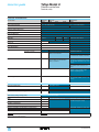
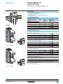
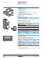
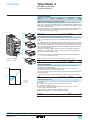
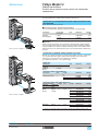
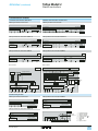
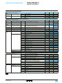
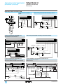
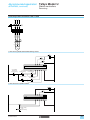
1
Telemecanique
TeSys® Model U – the
ultimate starter-controller
Catalogue
06
Contents
TeSys Model U
Starter-controllers
0
b Selection guide . . . . . . . . . . . . . . . . . . . . . . . . . . . . . . . . . . . . . . . . . . . . pages 2 and 3
b Presentation . . . . . . . . . . . . . . . . . . . . . . . . . . . . . . . . . . . . . . . . . . . . . . . .pages 4 to 7
b Application examples . . . . . . . . . . . . . . . . . . . . . . . . . . . . . . . . . . . . . . . . .pages 8 to 13
b Power bases
y
Non-reversing . . . . . . . . . . . . . . . . . . . . . . . . . . . . . . . . . . . . . . . . . . . . . . . . page 14
y
Reversing. . . . . . . . . . . . . . . . . . . . . . . . . . . . . . . . . . . . . . . . . . . . . . . . . . . . page 15
b Add-on contact blocks and auxiliary contact modules . . . . . . . . . . . . . . . . . . . . page 16
b Power connection pre-wired system . . . . . . . . . . . . . . . . . . . . . . . . . . . . . . . . . page 17
b Limiter blocks . . . . . . . . . . . . . . . . . . . . . . . . . . . . . . . . . . . . . . . . . . . . . . . . . . . page 17
b Accessories . . . . . . . . . . . . . . . . . . . . . . . . . . . . . . . . . . . . . . . . . . . . . . . . . . . . page 17
b Control units . . . . . . . . . . . . . . . . . . . . . . . . . . . . . . . . . . . . . . . . . . . . . .pages 18 to 20
b Function modules . . . . . . . . . . . . . . . . . . . . . . . . . . . . . . . . . . . . . . . . . . . . . . . page 21
b PowerSuite advanced dialogue solution . . . . . . . . . . . . . . . . . . . . . . . pages 22 and 23
b Model U controllers . . . . . . . . . . . . . . . . . . . . . . . . . . . . . . . . . . . . . . . pages 24 and 25
b Parallel wiring module and pre-wired coil connection components . . . pages 26 and 27
b Communication module and pre-wired coil connection components
y
AS-Interface . . . . . . . . . . . . . . . . . . . . . . . . . . . . . . . . . . . . . . . . . . . pages 28 and 29
y
Modbus . . . . . . . . . . . . . . . . . . . . . . . . . . . . . . . . . . . . . . . . . . . . . . pages 30 and 31
b Gateways . . . . . . . . . . . . . . . . . . . . . . . . . . . . . . . . . . . . . . . . . . . . . . . pages 32 and 33
b Characteristics . . . . . . . . . . . . . . . . . . . . . . . . . . . . . . . . . . . . . . . . . . . . .pages 34 to 41
b Tripping and limitation curves . . . . . . . . . . . . . . . . . . . . . . . . . . . . . . . . . pages 42 to 45
b Selection curves . . . . . . . . . . . . . . . . . . . . . . . . . . . . . . . . . . . . . . . . . pages 46 and 47
b Dimensions . . . . . . . . . . . . . . . . . . . . . . . . . . . . . . . . . . . . . . . . . . . . . pages 48 and 49
b Schemes . . . . . . . . . . . . . . . . . . . . . . . . . . . . . . . . . . . . . . . . . . . . . . . . .pages 50 to 55
b Recommended application schemes. . . . . . . . . . . . . . . . . . . . . . . . . . . . pages 56 to 59
To download this catalogue and for further information on
TeSys Model U and other Telemecanique products, log on to:
www.schneider.co.uk
Our company’s policy is one of continuous development and improvement and we reserve the right to supply products which may differ from those illustrated in this catalogue.
Schneider Electric
1
Selection guide
TeSys Model U
Starter-controllers
Function performed
Function not performed
Selectable overload class
Detection of overtorque, no-load running, long starting times
Earth fault protection (equipment protection only)
Protection against phase imbalance
Protection against phase loss
Fault differentiation
With contact block
Reset on thermal overload
Manual or
automatic
Manual
Manual or
automatic
Manual
Alarms (thermal overload, overcurrent, ...)
Indication of motor load
Protection function parameter entry
"Log" function, monitoring
Remote motor starter status and commands via serial or
parallel link
Motor starter management via serial link (status,
commands, selection and parameter entry for alarms,
log, monitoring)
Modbus port
built-in
Isolation function
Protection against overloads and short-circuits
Power at 400 V
2
With circuit-breaker
With fuses
0.06…75 kW
0.06…75 kW
30…450 kW
30…450 kW
0.06…450 kW
0.06…450 kW
0.06…110 kW
Magnetic
circuit-breaker
or fuses
Magnetic
circuit-breaker
or fuses
Magnetic
circuit-breaker
or fuses
Thermal magnetic
circuit-breaker
Contactor
Contactor
Contactor
Contactor
Thermal
overload relay
Electronic thermal
overload relay
Multifunction
protection relay
Schneider Electric
Manual
With function module
Indication on front panel,
processing by communication
Remote or automatic with function module
Reset parameters can be set to manual or
automatic
With function module
Indication on front panel,
processing by communication
Indication on front panel,
processing by communication
With function module
Indication on front panel, processing by
communication
With communication
module or control
splitter box
With AS-Interface or Modbus
communication module
(1)
With AS-Interface or Modbus communication module
(indication of motor load and thermal overload alarm only with Modbus communication module)
(1)
(1)
With Modbus communication module
0.06…11 kW
Quickfit solution
0.06…15 kW
Starter-controller with
standard control unit
0.06…15 kW
Starter-controller with
advanced control unit
16.5…450 kW
0.06…450 kW
Magnetic
circuit-breaker or fuses
0.06…15 kW
Starter-controller with
multifunction control unit
16.5…450 kW
0.06…450 kW
Magnetic
circuit-breaker or fuses
Contactor
Contactor
Controller with
advanced control unit
Controller with
multifunction control unit
(1) Parallel wiring module
Schneider Electric
3
Presentation
TeSys Model U
Starter-controllers
Presentation
6
2
The TeSys model U starter-controller is a D.O.L. starter (1) which performs the following
functions :
b protection and control of single-phase or 3-phase motors:
v breaking function,
v overload and short-circuit protection,
v thermal overload protection,
v power switching,
b control of the application:
v protection function alarms,
v application monitoring (running time, number of faults, motor current values, ...),
v logs (last 5 faults saved, together with motor parameter values).
These functions can be added by selecting control units and function modules which simply clip
into the power base The product can therefore be customised at the last moment. Setting-up
accessories simplify or completely eliminate wiring between components.
Basic starter-controller
1
3
4
5
8
7
Consists of a power base and a control unit.
Power base 1
Is independent of the control voltage and of the motor power.
It incorporates the breaking function with a breaking capacity of 50 kA at 400 V, total coordination
(continuity of service) and the switching function.
b 2 ratings are available: 0…12 A and 0…32 A.
b Non-reversing (LUB) and reversing (LU2B).
Control units 2
These must be selected according to the control voltage, the power of the motor to be protected
and the type of protection required.
b Standard control unit (LUCA) : satisfies the basic protection requirements for motor starters:
thermal overload and short-circuit (for details see page 5).
b Advanced control unit (LUCB, LUCC or LUCD) : allows additional advanced functions such
as alarm, fault differentiation, … (for details see page 6).
b Multifunction control unit (LUCM) : suitable for the most sophisticated control and protection
requirements (for details see page 7).
The control units are interchangeable without rewiring and without using tools. They have a wide
range of adjustment (0.25 - 1.0 x In) and low heat dissipation.
Control options
Function modules can be used to increase the functions of the starter-controller.
Function modules 3
Must be used with advanced control units.
4 types are available:
b thermal overload alarm (LUF W10),
b fault differentiation and manual reset (LUF DH11),
b fault differentiation and automatic or remote reset (LUF DA10 + LUF DA01),
b indication of motor load (LUF V), which can also be used with the multifunction control unit.
All information processed by these modules is available on digital contacts.
Communication modules 3
The information processed is exchanged:
b via a parallel bus:
v parallel wiring module (LUF C00),
b via a serial bus:
v AS-Interface module (ASILUF C5),
v Modbus module (LUL C033).
They must be used in conjunction with a c 24 V control unit and require a c 24 V control
voltage. Connection to other protocols such as FIPIO, Profibus-DP and DeviceNet is possible
via gateway modules (LUFP).
Auxiliary contact modules (LUFN) 3
3 possible configurations 2 N/O, 1 N/O + 1 N/C or 2 N/C.
Add-on contact blocks 4
Indicate the following status of power base : ready, fault and pole status.
Power options
Reverser block 5
Allows a non-reversing power base to be converted to reversing operation.
The reverser block (LU2M) is mounted directly beneath the power base without modifying the
width of the product (45 mm). The reverser block LU6M is mounted separately from the power
base when the height available is limited.
Limiter-disconnector LUA LB 6
This unit is mounted directly on the power base. It allows the breaking capacity to be increased
up to 130 kA at 400 V.
Setting-up accessories
Plug-in terminal blocks 7
The control terminal blocks are of the plug-in type, so allowing wiring to be prepared away from
the machine or the replacement of products without rewiring.
Control circuit wiring system 8
Numerous pre-wired accessories provide simple, clip-in connections (e.g. connection of reverser
control terminals, ...
(1) For use with resistive and inductive loads. Control of d.c. or capacitive loads is not possible.
4
Schneider Electric
Presentation
TeSys Model U
Starter-controllers
with standard control unit
b
b
b
b
Protection against overloads and short-circuits
Protection against phase failure and phase imbalance
Protection against insulation breaks (equipment protection only)
Manual reset
3-phase motor
Class 10
Power base
LUB or LU2B
Standard control unit
LUCA
Status
Status and commands transmitted by the bus
Parallel bus
Blanking cover
LU9C 1
Auxiliary contact
module
LUF N
Parallel wiring
module
LUF C00
Serial bus
AS-Interface
communication
module
ASILUF C5
Modbus
communication
module
LUL C033
Status
Add-on contact
blocks LUA1
Schneider Electric
Blanking cover
LU9C 2
5
Presentation
TeSys Model U
0
Starter-controllers
with advanced control unit
b
b
b
b
Protection against overloads and short-circuits
Protection against phase failure and phase imbalance
Protection against insulation breaks (equipment protection only)
Manual reset (remote or automatic with a function module)
3-phase motor
Class 20
Single-phase motor
Class 10
520727
3-phase motor
Class 10
Power base
LUB or LU2B
Advanced control
unit LUCB
Status
Fault
differentiation
and manual
reset
Fault
differentiation
and automatic
reset
Alarm
Advanced control
unit LUCD
Indication of
motor load
(analogue)
Advanced control
unit LUCC
Status and commands transmitted by the bus
Parallel bus
Serial bus
b Fault differentiation
and manual,
remote or
automatic reset
b Alarm
b Indication of motor
load
Blanking
cover LU9C 1
Auxiliary
contact
module
LUF N
Function
module
LUF DH11
Function
module
LUF DA10
+ LUF DA01
Function
module
LUF W
Function
module
LUF V
Parallel wiring
module
LUF C00
AS-Interface
communication
module
ASILUF C5
Modbus
communication
module
LUL C033
Status
Add-on contact
blocks LUA1
6
Blanking cover
LU9C 2
Schneider Electric
Presentation
TeSys Model U
Starter-controllers
with multifunction control unit
b Protection against overloads and short-circuits
b Protection against phase failure and phase imbalance
b Protection against insulation breaks (equipment protection only)
b Reset parameters can be set to manual or automatic
b Protection function alarm
b Indication on front panel or on remote terminal via Modbus RS 485 port
b "Log" function
b "Monitoring" function, indication of main motor parameters on front panel of the
control unit or via a remote terminal
b Fault differentiation
b Overtorque, no-load running
Single-phase or 3-phase motors
Class 5, 10, 15, 20, 25, 30
Power base
LUB or LU2B
Multifunction control unit
LUCM
Status
Indication of
motor load
(analogue)
Status and commands transmitted by the bus
Parallel bus
Serial bus
Remote programming
and monitoring of all
functions
Blanking
cover
LU9C 1
Auxiliary
contact
module
LUF N
Function
module
LUF V
Parallel wiring
module
LUF C00
AS-Interface
communication
module
ASILUF C5
Modbus
communication
module
LUL C033
Status
Add-on contact blocks
LUA1
Schneider Electric
Blanking
cover
7
Application examples
TeSys Model U
520965
Starter-controllers
Application
Starting and protection of a pump.
Operating conditions
b
b
b
b
b
v
v
b
Power : 4 kW at 400 V.
In : 9 A
Maximum of 10 class 10 starts per hour.
Duty class S3.
3-wire control :
Start button (S2),
Stop button (S1),
Control circuit voltage : a 230 V.
Products used
Products used
Power base 12 A with screw clamp
connections
Standard control unit
Item
1
Quantity Reference
1
LUB 12
2
1
LUCA 12FU
Page
14
19
Functions performed
561680
b Short-circuit protection with level of protection of 50 kA at 400 V.
b Total coordination of protection devices conforming to EN 60947-6-2 (continuity of
service) in case of a short-circuit.
b Electronic protection against thermal overloads with an adjustment range of
0.25 - 1.0 x In.
b Load switching (2 million operating cycles in category AC-43 at In).
b Indication of motor status by N/C or N/O contact.
b Interlock between the motor starter control and the selector switch position; not
possible to start the motor when the switch is in the OFF position.
230 V
13
5/L3
3/L2
1/L1
Scheme
A1
6/T3
–
A2
W1
4/T2
V1
U1
2/T1
14
C.U.
M
3
8
Schneider Electric
Application examples
TeSys Model U
561681
Starter-controllers
Application
Expansion of an existing installation to meet the operating conditions described
below.
Operating conditions
Monitor the status of the motor and obtain alarm signalling by a digital contact in
order to improve operation of the pump and anticipate a complete stoppage due to
thermal overload.
Additional products used
Products used
Item
Quantity Reference
Page
Replace the standard control unit with an advanced control unit and insert a thermal
overload alarm function module.
Advanced control unit
Alarm function module
2
3
1
1
LUCB 12FU
LUF W10
19
21
Functions performed
b Alarm information is generated by the advanced control unit and is processed by
the thermal overload alarm function module to make it usable.
b The advanced control unit includes a thermal trip Test button on its front panel.
a 230 V
13
5/L3
3/L2
1/L1
Scheme
M
3a
Other versions
Schneider Electric
A1
6/T3
LUF W10
07
Alarms Module
08
To
application
–
A2
W1
4/T2
V1
U1
2/T1
14
C.U.
a
The advanced control unit can provide other functions,
depending on the type of function modules used (instead of
the LUF W module described above) :
- fault differentiation with function module LUF DA10,
LUF DA01 or LUF DH11,
- indication of motor load with function module LUF V2. This
module delivers a 4-20 mA, analogue signal which is
proportional to the average 3-phase current drawn by the
motor. This allows the load current to be monitored and
provides access to other application functions using this
value, or to predictive or preventive maintenance
possibilities (replacement of the motor before it breaks
down).
9
Application examples
TeSys Model U
Starter-controllers
520969
Application
Monitoring operation of a surface pump in a water treatment plant to avoid running
empty, which could lead to destruction of the pump.
Operating conditions
b
b
b
b
b
Power : 15 kW at 400 V.
In : 28.5 A
Duty class S1.
Control circuit voltage : c 24 V.
Control-command by PLC and serial link using the Modbus protocol.
Products used
510301
Products used
Power base 32 A without connections
Multifunction control unit
Modbus communication module
Pre-wired coil connection
Connection of communication module
output terminals to the coil terminals
Connection cable for connecting the
communication module to the serial bus
T-junction
Item
1
2
3
4
Quantity
1
1
1
1
Reference
LUB 320
LUCM 32BL
LUL C033
LU9B N11C
Page
14
20
30
31
–
1
pp
VW3 A8 306 Rp
31
–
1
VW3 A8 306 TF03
31
Functions performed
b Short-circuit protection with level of protection of 50 kA at 400V.
b Total coordination of protection devices conforming to EN 60947-6-2 (continuity of
service) in case of a short-circuit.
b Electronic protection against thermal overloads with an adjustment range of 0.25
- 1.0 xIn.
b Load switching (1.5 million operating cycles in category AC-43 at In).
b Measurement of load current and detection of no-load running by the multifunction
control unit.
b Interlock between the motor starter control and the selector switch position; not
possible to start the motor when the switch is in the OFF position.
b No-load running or operation under load. To use this function, the following
parameters must be entered :
v trip : the answer yes/no enables or disables the function,
v time before tripping : the time period during which the value of the current must be
below the tripping threshold in order to cause tripping (adjustable from 1 to 200 s).
v tripping threshold : value as a % of the load current ratio in relation to the setting
current. If the ratio remains below this threshold for the time specified in the previous
parameter, the product trips (adjustable from 30 to 100 %).
b Indication of the various motor starter status and currents.
4 5 8
LU9B N11C
N11C
LU9B
Pre-wired
coil
Pre wired coil
24 V 24
24VVAux
c Aux COM
D (B)
D (A)
Gnd
Modbus Module
Modbus Module
LUL C033
LO1
LI1
LI2
Multifunction
Multifunction
Control
Control Unit
Unit
D (B)
D (A)
Gnd
5/L3
LUCM
24
24VVAux
Aux
4 5 8
C.U.
C.U.
+
W1 6/T3
Status (Register 455)
Ready (available)
Poles closed
Fault
Alarms
Reserved
Reserved
Reserved
Motor running
Motor current % (bit 0)
Motor current % (bit 1)
Motor current % (bit 2)
Motor current % (bit 3)
Motor current % (bit 4)
Motor current % (bit 5)
Reserved
Motor starting
V1 4/T2
Bit 0
Bit 1
Bit 2
Bit 3
Bit 4
Bit 5
Bit 6
Bit 7
Bit 8
Bit 9
Bit 10
Bit 11
Bit 12
Bit 13
Bit 14
Bit 15
U1 2/T1
Modbus profile IEC 64915
Commands (Register 704)
Forward running
Reverse running
Reserved
Reset
Reserved
Connection test
Reserved
Reserved
Reserved
Reserved
Reserved
Reserved
Reserved
Reserved
Reserved
Reserved
3/L2
1/L1
Schemes
M
3a
c 24 V
Modbus
VW3 A8 306 TF03
Other functions
The multifunction control unit incorporates other control and protection functions, such
as : monitoring and control of phase current, alarm, …
Module LUL C033 also provides a programmable output.
10
Schneider Electric
Application examples
TeSys Model U
520967
Starter-controllers
Application
Starting and control of a packing machine conveyor belt.
Operating conditions
b
b
b
b
b
Power : 0.37 kW at 400 V.
In : 0.98 A
Duty class S1.
Control circuit voltage : c 24 V
Control and command by the AS-Interface wiring system.
Products used
Products used
Power base 12 A without connections
Standard control unit
AS-Interface communication module
Tap-off for connecting the communication
module to the serial bus
Pre-wired coil connection
Connection of communication module
output terminals to the coil terminals
Item
1
2
3
–
Quantity
1
1
1
1
Reference
LUB 120
LUCA 1XBL
ASILUF C5
XZ CG0142
Page
14
19
28
29
4
1
LU9B N11C
29
521489
Functions performed
b Short-circuit protection with level of protection of 50 kA at 400 V.
b Total coordination of protection devices conforming to EN 60947-6-2 (continuity of
service) in case of a short-circuit.
b Electronic protection against thermal overloads with an adjustment range of 4.
b Load switching (2 million operating cycles in category AC-43 at In).
b Indication of motor status by N/C or N/O contact.
b Interlock between the motor starter control and the selector switch position; not
possible to start the motor when the switch is in the OFF position.
b Start/Stop commands and Ready, Running and Stopped motor status are
transmitted by the bus. The AS-Interface 7.D.F.O profile of the new AS-Interface V2
protocol, implemented in the starter-controller, ensures total compatibility with that of
the LF enclosed starter range.
b Indication of module operation and communication status by 2 LEDs on the front
panel of the communication module.
b Addressing of the module is achieved, using adjustment console ASI TERV2 or
console XZ MC11. Using pre-wired coil connector LU9B N11C avoids having to wire
the control connections. However, easy access to the control connector on the front
panel of the starter allows any control schemes required by the user to be included
in the line (local controls, emergency stop, safety contact, .....)
Scheme
AS-Interface Module
LU9B N11C
Pre-wired coil
C.U.
Schneider Electric
11
Application examples
TeSys Model U
Starter-controllers
520971
Application
Manual control of a 2-position turntable.
Operating conditions
b
b
b
b
b
v
v
v
b
b
Power : 2.2 kW at 400 V.
In : 6 A
30 starts per hour
Duty class S4.
3-wire control :
Pushbutton for Position 1 (S1),
Pushbutton for Position 2 (S2),
Stop button (S5),
Stopping at the positions is achieved by limit switches S3 and S4.
Control circuit voltage : a 115 V.
Products used
561684
Products used
Power base reversing, 12 A with screw
clamp connections
Standard control unit
Item
1
Quantity Reference
1
LU2B 12FU
2
1
Page
15
LUCA 12FU
19
Functions performed
b Short-circuit protection with level of protection of 50 kA at 400V.
b Total coordination of protection devices conforming to EN 60947-6-2 (continuity of
service) in case of a short-circuit.
b Electronic protection against thermal overloads with an adjustment range of
0.25 - 1.0 x In.
b Load switching (2 million operating cycles in category AC-43 at In).
b Interlock between the motor starter control and the selector switch position; not
possible to start the motor when the switch is in the OFF position.
Electrical interlocking is ensured by pre-wired connector LU9M R1C (item 3)
included on base LU2B 12. The design of the reversing power block makes
mechanical interlocking unnecessary.
A1
B3
A3
A2
Reverser Motor Controller
LU2B
B1
5/L3
3/L2
1/L1
Scheme (manual control)
M
3
12
W1
6/T3
4/T2
V1
U1
2/T1
C.U.
115 V
Schneider Electric
Application examples
TeSys Model U
Controllers
520973
Application
Monitoring blockage of a rock crusher by monitoring the motor current.
Operating conditions
b
b
b
b
b
Power : 90 kW at 400 V.
In : 185 A
Duty class S1.
Control circuit voltage : a 230 V
Control-command by PLC and serial link using the Modbus protocol.
Products used
Products used
Controller
Multifunction control unit
Modbus communication module
Current transformers
Contactor
Circuit-breaker
Item
1
2
3
4
5
6
Quantity
1
1
1
3
1
1
Reference
LUT M
LUCM T1BL
LUL C033
LUT C4001
LC1 F185P7
NS 250HMA
Page
25
25
30
25
–
–
561271
Functions performed
b Short-circuit protection with level of protection of 70 kA at 400V.
b Electronic protection against thermal overloads with an adjustment range of 0.25
- 1.0 x In
b Detection of crusher blockage by monitoring the induced overcurrent. To use the
"overtorque or jam" function, the following parameters must be entered :
v trip : the answer yes/no enables or disables the function,
v time before tripping : the time period during which the value of the current must be
above the tripping threshold in order to cause tripping (adjustable from 1 to 30 s).
v tripping threshold : value as a % of the load current ratio in relation to the setting
current. If the ratio remains above this threshold for the time specified in the previous
parameter, the product trips (adjustable from 100 to 800 %).
It is possible to set the parameter for an alarm at a preset threshold under the same
conditions as above.
4 5 8
- KA1
From S1/T1, S1/T2, S1/T3,
S2/T1, S2/T2, S2/T3
- KA1
- T2
- Q6
13
- KM1
To - KA1
- Q6
S1
A1
- T3
- KM1
A2
S2
S2
S1
+
5/L3
3/L2
1/L1
96
24 V 24V
c Aux COM
230 V a
D (B)
D (A)
Gnd
LI2
LI1
I.7
I.6
L3
L1
L2
D (B)
D (A)
Gnd
6/T3
4/T2
2/T1
24 V Aux
4 5 8
S1
S2
S1
- KA1
Modbus Module
LUL C033
S2
- Q6
- T1
- KA1
Controller
LUT M20BL
LO1
- KA1
LUCM T1BL
Multifunction Control Unit
I.3
5/L3
3/L2
1/L1
Scheme
c 24 V
W1 6T3
V1 4T2
U1 2T1
- KM1
- KA1
Modbus
VW3 A8 306 TF03
a
M
3a
Other functions
The multifunction control unit incorporates other control and protection functions,
such as : monitoring and control of phase currents, alarm, …
Communication module LUL C033 also provides a programmable output and two
programmable inputs.
Schneider Electric
13
References
TeSys Model U
Starter-controllers
561330
520739
Non-reversing power bases
Two versions of control connection are available:
b connection by screw terminals, plug-in control terminal block,
b without connection. This version enables wiring to be prepared in advance and
is recommended when a communication module is required (allowing the use of
control connection prewiring accessories) or when a reverser block is to be mounted
by the customer.
520740
Power bases for non-reversing D.O.L. starting (1)
Connection
Power
Control
Item
(2)
Rating
≤ 440 V 500 V
A
A
Reference
Weight
690 V
A
kg
These bases have 2 auxiliary contacts: 1 N/O (13-14) and 1 N/C (21-22) which
indicate the closed or open position of the power poles.
LUB p2
LUB p20
They must be used in conjunction with a control unit, see pages 18 to 20.
Screw
terminals
Screw
terminals
1 + 2 + 3 12
+4
32
Without
1+2
connections
1
2
Screw terminals
4
LUB p2
14
Dimensions :
pages 48 and 49
LUB 12
0.900
23
21
LUB 32
0.900
12
12
9
LUB 120
0.865
32
23
21
LUB 320
0.865
For base
LUB 120 or 320
Item
(2)
3+4
Reference
LU9B N11
Weight
kg
0.045
(1) Rated breaking capacity for operation on short-circuit (Ics), see table below.
For higher values, use current limiters, see page 17.
Volts
230
440
500
690 (3)
kA
50
50
10
4
(2) The various sub-assemblies are supplied assembled but they are easy to separate, as shown
in the illustration.
(3) For 690 V, use phase barrier LU9 SP0.
Other versions
Characteristics :
pages 34 and 35
9
Terminal blocks for power bases without connections
Connection
3
12
Power bases without built-in short-circuit protection device
(short-circuit protection by circuit-breaker or separate
fuses).
Please call our Customer Information Centre
on 0870 608 8 608.
Schemes :
pages 50 to 54
Schneider Electric
References
TeSys Model U
Starter-controllers
561270
Reversing power bases
Two versions of control connection are available:
b connection by screw terminals, plug-in control terminal block,
b without connection. This version enables wiring to be prepared in advance and
is recommended when a communication module is required, allowing the use of
control connection pre-wiring accessories.
Power bases for reversing D.O.L. starting, pre-assembled
Connection
Power
Control
Item
(1)
Rating
≤ 440 V 500 V
A
A
690 V
A
Reference to be
completed (2)
Weight
kg
These bases have two N/O common point contacts (81-82-84) which indicate nonreversing and reversing operating status.
Screw
terminals
Screw
terminals
1 + 2 + 3 12
+ 4 + 5 32
Without
1 + 2 + 3 12
connections + 5
32
12
23
12
23
9
21
9
21
pp
LU2B 12p
pp
LU2B 32p
pp
LU2B A0p
pp
LU2B B0p
1.270
1.270
1.270
1.250
520741
Power bases for reversing D.O.L. starting, mounted by the
customer
A reverser block should preferably be combined with a non-reversing power base
without connections to create a reversing starter-controller.
The built-in N/O (13-14) and N/C (21-22) contacts are used for electrical interlocking
between the reverser block and the base; they are therefore no longer available as
output contacts.
The reverser block has a C/O common point contact (81-82-84) which indicates
non-reversing and reversing operating status.
LU2B p2
1
32 A reverser block
Connection
Power
For mounting directly
Screw
beneath the power base terminals
For mounting separately Screw
from the base
terminals
(screw or rail fixing)
2
Item (1) Reference to be
completed (2)
Control
Without
3
connections
Without
6
connections
Weight
kg
pp
LU2M B0p
0.400
pp
LU6M B0p
0.425
Accessories
Description
Item
Control block 4
3
5
7
Application
Reference
Non-reversing power base
LU9 M1
without connections LU2B A0pp or B0pp
Reverser block LU2M B0pp for direct
LU9 M1
mounting beneath power base
Reverser block LU6M B0pp for mounting LU9 M1
separately from power base
Reverser block LU6M B0pp for mounting LU9M R1
separately from power base
Weight
kg
0.025
0.025
0.025
0.030
Control circuit pre-wiring components
520826
Description
4
Pre-wired connector (3)
LU2B p2
Item
Reference
5
LU9M R1C
Weight
kg
0.035
(1) The various sub-assemblies are supplied assembled but they are easy to separate, as shown
in the illustration.
(2) Select the same control voltage as that of the control unit.
Standard control circuit voltages :
Volts
24
48…72
110…240
c
BL
–
–
a
B
–
–
c or a
–
ES (4)
FU (5)
(3) For control connection between a power base and a reverser block, for direct mounting.
(4) c : 48…72 V, a : 48 V.
(5) c : 110…220 V, a : 110...240 V.
6
7
Other versions
4
Power bases without built-in short-circuit protection device
(short-circuit protection by circuit-breaker or separate fuses).
Please call our Customer Information Centre
on 0870 608 8 608.
LU6M + LU9 M1 + LU9M R1
Characteristics :
pages 34 and 35
Schneider Electric
Dimensions :
pages 48 and 49
Schemes :
pages 50 to 54
15
Presentation,
references
TeSys Model U
Starter-controllers
Add-on contact blocks and auxiliary contact modules
Contact states
Product status
References of add-on contact blocks
and auxiliary contact modules
Terminal referencing
Position of
control
handle
Indication
on front
panel
N/O pole
contact
N/C pole
contact
N/O
contact
any fault
N/C contact
any fault
–
–
–
or
–
–
–
LUA1 C20
97-98
–
or
–
–
–
LUA1 C11
95-96
LUA1 C110
no terminal
block
–
or
–
–
LUF N20
33-34
43-44
LUF N11
43-44
LUF N11
31-32
LUF N02
31-32
41-42
LU9B N11
21-22
–
–
–
or
–
–
–
–
–
Connection
Item
Reference
Screw terminals
1+2
LUA1 C11
Without
connections
1
LUA1 C110
0.012
Screw terminals
1+2
LUA1 C20
0.030
Without
connections
1
LUA1 C200
0.012
Off
LU9B N11
13-14
N//O contact
product
ready
LUA1 C20
17-18
LUA1 C200
no terminal
block
LUA1 C11
17-18
LUA1 C110
no terminal
block
–
0
OFF
Ready to operate
0
Running
1
Tripped on short-circuit
Tripped on
thermal overload
Manual reset mode
TRIP
I>>
TRIP
0
Automatic reset on thermal overload
mode
0
Remote reset mode
0
N/O contact
N/C contact
in closed position
in open position
References
Add-on contact blocks
Signalling and composition
3
4
6
Auxiliary contact modules for connection by screw clamp terminals
Module with 2 contacts indicating the state of the starter-controller power poles
Application : a or c 24…250 V, Ith : 5 A
Composition
1
2
5
1 N/C fault signalling
contact (95-96) and
1 N/O contact (17-18) indicating
control handle in “ready”
position
1 N/O fault signalling
contact (97-98) and
1 N/O contact (17-18) indicating
control handle in “ready”
position
Weight
kg
0.030
2 NO contacts (33-34 and 43-44)
1 NC contact (31-32) and 1 NO contact (43-44)
2 NC contacts (31-32 and 41-42)
Item
Reference
3
3
3
LUF N20
LUF N11
LUF N02
Item
Reference
2
2
LU9B C11
LU9B C20
Weight
kg
0.050
0.050
0.050
Accessories
Description
For use on
LUB + LUA1 + LUF N
Screw clamp
LUA1 C110
terminal blocks LUA1 C200
Blanking covers Location for auxiliary contact,
4
communication or function module
Location for add-on contact blocks 5
Side mounted LUBpp
6
auxiliary
contacts
(2 N/O)(1)
Weight
kg
0.022
0.022
LU9C 1
0.020
LU9C 2
LUA8 E20
0.010
0.010
(1) For disconnection of motor control circuits
Characteristics :
page 36
16
Schemes :
page 50
Schneider Electric
References
TeSys Model U
0
Starter-controllers
533843
Power connection pre-wired system, limiter blocks
and accessories
Pre-wired system for power connections up to 63 A
Description
4 1
8
Application
Pitch
mm
45
54
45
54
45
54
54
–
2
Sets of 3-pole
63 A busbars
3
2 tap-offs
3 tap-offs
533844
4 tap-offs
5
5 tap-offs
Protective
For unused
end cover
busbar outlets
Terminal block for Connection
–
supply to one or from the top
more busbar sets
6
Item
2
–
–
–
1
–
–
4
Sold in
lots of
1
1
1
1
1
1
1
5
Unit
reference
GV2 G245
GV2 G254
GV2 G345
GV2 G354
GV2 G445
GV2 G454
GV2 G554
GV1 G10
3
1
GV1 G09
Weight
kg
0.036
0.038
0.058
0.060
0.077
0.085
0.100
0.005
0.040
Pre-wired system for power connections up to 160 A
The busbar system can be screw-mounted onto any type of support.
Set of 4-pole busbars: 3-phase + neutral or 3-phase + common
Number of
Item
tap-offs at
18 mm intervals
18
5
Length
mm
452
For mounting in
enclosure width
mm
800
Reference
AK5 JB144
Weight
kg
0.900
Removable 3-phase power sockets
Number of points Thermal
used on the
current
busbar system
2
16
32
Item
Cable
lengths
6
6
200
250
1000
Sold in Unit
lots of reference
6
6
6
AK5 PC13 (1)
AK5 PC33 (1)
AK5 PC33L (1)
Weight
kg
0.040
0.045
0.060
Limiter blocks and accessories
533845
Application
Limiterdisconnector (3)
(6)
Current limiters
(3)
Limiter cartridge
Clip-in
marker holder
7
10
8
Item
Breaking
Mounting
capacity Iq
≤ 440 V 690 V
kA
kA
130
70
Direct on
power base
Unit
reference
LUA LB1 (2)
kg
0.310
8
100
35
Separate
LA9 LB920
0.320
10
–
130
–
70
–
Limiter-disconnector LUA LF1
On power base,
LAD 90 (4)
on reverser block,
on parallel link
splitter box
0.135
0.001
7 + 10
Weight
561524
Phase barrier
9
Phase barrier LU9 SP0 must be used:
b To build a UL 508 type E certified starter (Self Protected Starter).
Without the phase barrier, the starter-controller is certified UL 508.
b If the starter-controller is to be used on an operational voltage of 690 V.
Description
Phase barrier
Item
Application
Mounting Reference
9
LUB or LU2B 12 or 120
LUB or LU2B 32 or 320
LUA LB1
Direct on LU9 SP0
terminals
L1, L2, L3
Weight
kg
0.030
561425
Door interlock mechanisms
Description
11
12
13
Item
Reference
Weight
kg
0.490
0.150
0.150
11 + 12 LU9 AP00
Fixing kit (5) (7)
Door-mounted black handle/blue front plate, IP54
13
LU9 AP11
Door-mounted red handle/yellow front plate, IP54
13
LU9 AP12
(1) The maximum permissible peak current for power sockets AK5 PCpp is 6 kA.
When used in association with power bases LUBpp, the prospective short-circuit current must
not exceed 7 kA
(2) Supplied with limiter cartridge.
(3) These devices make it possible to increase the breaking capacity of the power base.
(4) Sold in lots of 100.
(5) The fixing kit includes a shaft extension (maximum depth 508 mm).
(6) The limiter must be mounted on an LUB or LU2B power base. The limiter can therefore not
be common to several motor starters.
(7) To use the fixing kit with a D.O.L. reversing power base, only reverser block LU6 M must be
used.
Dimensions :
pages 48 and 49
Schneider Electric
17
Selection guide
TeSys Model U
Starter-controllers
Control units
Function characteristics
Control units
Standard
LUCA
Thermal overload protection
Overcurrent protection
Advanced
LUCB
LUCC
LUCD
14.2 x the setting current
Short-circuit protection
Protection against phase loss
Multifunction
LUCM
3 to 17 x the setting current
14.2 x the max. current
Protection against phase imbalance
Earth fault detection
(equipment protection only)
Tripping class
Motor type
10
3-phase
10
20
Single-phase 3-phase
5…30
Single-phase and 3-phase
Thermal overload test function
Overtorque
No-load running
Long starting times
Reset mode
Manual
Automatic or remote
Parameters can be set
With function module or parameters can Parameters can be set
be set via the bus with a communication
module, see chart below.
Parameters can be set via the bus with
a communication module (see below).
Thermal overload alarm only with
function module or communication
module, see below.l
Alarm
"Log" function
Possible for each type of fault.
Indication on front panel of the control
unit, via remote terminal, via PC or via
PDA (1).
With communication modules to make
use of these alarms via a bus, see
below.
Log of the last 5 trips.
Number of starts, number of trips,
number of operating hours.
Indication on front panel of the control
unit via remote terminal, via PC or via
PDA (1).
"Monitoring" function
With function modules (2)
Thermal overload alarm
Fault differentiation and manual reset
With module LUF W
With module LUF DH20
Fault differentiation and automatic reset
Indication of motor load (analogue)
With module LUF DA10
With module LUF V
With communication module or via Modbus port on control unit LUCM (2)
Starter status (ready, running, fault)
Reset mode
Alarm
With any communication module
Parameters can be set via the bus
With module Modbus LUL C032
(thermal overload alarm only).
Remote reset via the bus
Indication of motor load
Fault differentiation
Remote programming and monitoring of all functions
"Log" function
"Monitoring" function
Built-in function
With Modbus module LUL C032 and
Modbus port on the control unit (alarm
possible for all types of fault).
With Modbus module LUL C032 and
Modbus port on the control unit.
Function provided with accessory
(1) PDA : Personal Digital Assistant.
(2) Mounting possibilities: 1 function module or 1 communication module.
18
Schneider Electric
References
TeSys Model U
Starter-controllers
530655
Standard and advanced control units
Description
1
5
2
4
Extraction and locking handle
Test button (on advanced control unit only)
Ir adjustment dial
Locking of settings by sealing the transparent cover
Sealing of locking handle
Standard control units
Maximum power ratings of
standard 3-phase motors
50/60 Hz
400/ 415 V 500 V
690 V
kW
kW
kW
0.09
–
–
0.25
–
–
1.5
2.2
3
5.5
5.5
9
7.5
9
15
15
15
18.5
3
520735
LUCA pppp
LUCB pppp
1
2
3
4
5
Setting
range
Clip-in
mounting on
power base
Rating
Reference to be
Weight
completed by
adding the voltage
code (1)
A
0.15…0.6
0.35…1.4
1.25…5
3…12
4.5…18
8…32
A
12 and 32
12 and 32
12 and 32
12 and 32
32
32
pp
LUCA X6p
pp
LUCA 1Xp
pp
LUCA 05p
pp
LUCA 12p
pp
LUCA 18p
pp
LUCA 32p
kg
0.135
0.135
0.135
0.135
0.135
0.135
Advanced control units
Pressing the Test button on the front panel simulates tripping on thermal overload.
Class 10 for 3-phase motors
0.09
0.25
1.5
5.5
7.5
15
–
–
2.2
5.5
9
15
–
–
3
9
15
18.5
12 and 32
12 and 32
12 and 32
12 and 32
32
32
pp
LUCB X6p
pp
LUCB 1Xp
pp
LUCB 05p
pp
LUCB 12p
pp
LUCB 18p
pp
LUCB 32p
0.140
0.140
0.140
0.140
0.140
0.140
0.15…0.6
0.35…1.4
1.25…5
3…12
4.5…18
8…32
12 and 32
12 and 32
12 and 32
12 and 32
32
32
pp
LUCC X6p
pp
LUCC 1Xp
p
LUCC 05pp
pp
LUCC 12p
pp
LUCC 18p
pp
LUCC 32p
0.140
0.140
0.140
0.140
0.140
0.140
0.15…0.6
0.35…1.4
1.25…5
3…12
4.5…18
8…32
12 and 32
12 and 32
12 and 32
12 and 32
32
32
pp
LUCD X6p
pp
LUCD 1Xp
pp
LUCD 05p
pp
LUCD 12p
pp
LUCD 18p
pp
LUCD 32p
0.140
0.140
0.140
0.140
0.140
0.140
0.15…0.6
0.35…1.4
1.25…5
3…12
4.5…18
8…32
Class 10 for single-phase motors
–
0.09
0.55
2.2
4
7.5
520736
LUB p2 + LUCA pppp
–
–
–
–
–
–
–
–
–
–
–
–
Class 20 for 3-phase motors
0.09
0.25
1.5
5.5
7.5
15
–
–
2.2
5.5
9
15
–
–
3
9
15
18.5
(1) Standard control circuit voltages :
Volts
24
48…72
110…240
–
c
BL (2), (3) –
a
B
–
–
FU (5)
c or a
–
ES (4)
(2) Voltage code to be used for a starter-controller with communication module.
(3) d.c. voltage with maximum ripple of ± 10 %.
(4) c : 48…72 V, a : 48 V.
(5) c : 110…220 V, a : 110...240 V.
LUB p2 + LUCB pppp
Characteristics :
pages 34 and 35
Schneider Electric
Schemes :
pages 50 to 54
19
References
TeSys Model U
Starter-controllers
530656
Multifunction control units
Description
6
1
2
3
5
LUCM ppBL
4
1 Extraction and locking handle
2 Built-in display window (2 lines, 12 characters)
3 4-button keypad
4 c 24 V auxiliary power supply
5 Modbus RS485 communication port. Connection by RJ45 connector.
6 Sealing of locking handle
The display window 2 and keypad 3 allow :
b in configuration mode: local configuration of protection functions and alarms,
b in run mode: display of parameter values and events.
The Modbus communication port 5 is used to connect :
b an operator terminal,
b a PC,
b a Personal Digital Assistant (PDA).
Multifunction control units
520737
Parameter entry, monitoring of parameter values and consultation of logs are carried
out :
b either on the front panel, using the built-in display window/keypad,
b or via an operator terminal,
b or via a PC or a PDA with PowerSuite software,
b or remotely, via a Modbus communication bus.
Programming of the product via the keypad requires a c 24 V auxiliary power supply.
LUB p2 + LUCM ppBL
Maximum power ratings of
standard 3-phase motors
50/60 Hz
400/ 415 V 500 V
690 V
kW
kW
kW
0.09
–
–
0.25
–
–
1.5
2.2
3
Setting
range
Clip-in mounting
on power base
Rating
A
0.15…0.6
0.35…1.4
1.25…5
A
12 and 32
12 and 32
12 and 32
LUCM X6BL
LUCM 1XBL
LUCM 05BL
kg
0.175
0.175
0.175
5.5
7.5
15
3…12
4.5…18
8…32
12 and 32
32
32
LUCM 12BL
LUCM 18BL
LUCM 32BL
0.175
0.175
0.175
5.5
9
15
9
15
18.5
Reference
(1)
Weight
TeSys model U user's manual (2)
Application
On CD-Rom
Language
Reference
Multi-language (3)
LU9 CD1
Weight
kg
0.022
Operator terminal
521335
This compact Magelis terminal enables the parameters of multifunction control unit
LUCM to be read and modified.
It is supplied pre-configured to provide dialogue with 8 model U starter-controllers
(Modbus protocol, application pages and alarm pages loaded).
Starter-controller alarm and fault management takes priority.
Language
Multi-language (3)
Display window
Supply voltage
4 lines of 20 characters c 24 V
Reference
XBT NU400
Weight
kg
0.150
XBT NU400
Connecting cable (4)
Function
Length
Type
Reference
Weight
kg
0.200
Connects terminal XBT NU400 2.5 m
SUB-D 25-way
XBT Z938
to a multifunction control unit.
female - RJ45
(1) Input voltage c 24 V with maximum ripple of ± 10 %.
(2) The CD-Rom contains user's manuals for the AS-i and Modbus communication modules,
multifunction control units and gateway modules, as well as the gateway programming
software.
(3) English, French, German, Italian, Spanish
(4) If a terminal is used with several control units, this cable can be connected to a Modbus hub
or to T-junctions (see page 31).
Characteristics :
pages 34 and 37
20
Schemes :
pages 50 to 54
Schneider Electric
References
TeSys Model U
Starter-controllers
Function modules
Function modules
Output
Item
Application
Reference
Weight
kg
533846
Thermal overload signalling and manual reset
Module LUF DH11 makes it possible to differentiate thermal overload and shortcircuit faults. (The short-circuit fault can then be signalled via add-on contact blocks
LUA1 C). The module includes two contacts for thermal overload signalling, as well
as an LED on the front panel.
To reset the motor starter, the operator must use the rotary knob on the power base.
The module can only be used with an advanced control unit and requires an
a/c 24…240 V external powr supply.
4
3
2
1 N/O + 1 N/C
3
a or c 24…250 V
LUF DH11
0.060
Thermal overload signalling and automatic or remote reset
These modules make it possible to differentiate thermal overload and short-circuit
faults. (The short-circuit fault can then be signalled via add-on contact blocks
LUA1 C).
The modules include one contact for thermal overload signalling, as well as an LED
on the front panel. A second contact (terminals Z1-Z2) must be wired in series with
terminal A1 of the motor starter. In the event of a thermal overload fault, this wiring
allows motor control to be switched off. The rotary knob on the power base will then
stay in the "ready position" .
Resetting of the motor starter is automatic after the required motor cooling time if
terminals X1-X2 are linked by a strap, or remote by pulsed closing of a volt-free
contact connected to terminals X1-X2.
These modules can only be used with an advanced control unit and require an
a/c 24…240 V external powr supply.
510445
LUB p2 + LUCB pppp
+
LUFW 10 or LUF Vp
1
Note : Terminals X1-X2 are not isolated from the signalling module power supply.
1 N/C
4
a or c 24…250 V
LUF DA01
1 NO
4
a or c 24…250 V
LUF DA10
0.055
0.055
Thermal overload alarm
Through load shedding, this module makes it possible to avoid stoppages in
operation due to overload tripping.
Imminent thermal overload tripping is displayed as soon as the thermal state
exceeds the threshold of 105 % (hysteresis = 5 %).
Signalling is possible via an LED on the front panel of the module and externally by
an N/O relay output.
It can only be used with an advanced control unit, from which it takes its power.
%
200
100
1 N/O
1
2
3
4
1 2.2 kW
2 4 kW
3 7.5 kW
12 mA
20 mA
Schneider Electric
a or c 24…250 V
LUF W10
0.055
Indication of motor load
This module provides a signal which is representative of the motor load status
(I average/Ir).
b I average = average value of the rms currents in the 3 phases,
b Ir = value of the setting current.
The value of the signal (4-20 mA) corresponds to a load status of 0 to 200 %
(0 to 300 % for a single-phase load).
It can be used with an advanced or multifunction control unit.
Module LUF V2 requires a c 24 V external power supply.
4 - 20 mA
Characteristics :
pages 34 and 39
1
2
–
LUF V2
0.050
Schemes :
pages 50 to 54
21
Presentation
TeSys Model U
PowerSuite software workshop
advanced dialogue solutions
531819
Presentation
The PowerSuite software workshop, for PC or Pocket PC, is designed for setting up
Telemecanique starters and variable speed drives.
This single program is an easy-to-use interface for configuring Altistart and Tesys
model U starters as well as all Altivar drives in a Microsoft Windows® environment,
in five languages (English, French, German, Italian and Spanish).
Functions
The PowerSuite software workshop can be used for preparing, programming, setting
up and maintaining Telemecanique starters and variable speed drives.
531820
PowerSuite with PC screen
Installation management
The PowerSuite software workshop can be used:
b stand alone to prepare and store starter or drive configuration files,
b connected to the starter or drive to:
v configure,
v adjust,
v monitor (except for Altivar 11 drives),
v control (except for Altivar 11 drives),
v transfer and compare configuration files between PowerSuite and the starter or
drive.
The configuration files generated by the PowerSuite software workshop can be:
b saved to hard disk, CD-Rom, floppy disk, etc...
b printed,
b exported to office automation software applications,
b exchanged between a PC and a Pocket PC using standard synchronization
software. PowerSuite PC and Pocket PC configuration files have the same format,
b they are password protected.
The software associated with the Altivar 31 has been enhanced to include:
oscilloscope function, parameter name customisation, creation of a user menu,
creation of monitoring screens, searching and sorting on different parameters.
The PowerSuite software workshop has on-line contextual help.
531440
PowerSuite with PC screen
Monitoring screen
Connections
b The PowerSuite software workshop can be connected directly to the terminal port
on the starter or variable speed drives, via the serial port on the PC or Pocket PC.
Two types of connection are possible:
- either with a single starter or drive (point to point connection)
- or with a group of starters or drives (multi-point connection).
b The PowerSuite software workshop for PC can be connected to an Ethernet
network. In this case the starters and drives can be accessed using:
- either an Ethernet-Modbus 174 bridge CEV 300 20,
- or a communication option card VW3 A58310 (for Altivar 38, 58 and 58F drives
only).
Hardware and software environment
b The PowerSuite for PC software workshop can operate in the following PC
environments and configurations:
v Microsoft Windows® 95 OSR2, Microsoft Windows® 98 SE, Microsoft
Windows® NT4 X SP5, Microsoft Windows® Me, Microsoft Windows® 2000,
Microsoft Windows® XP,
v Pentium III, 800 MHz, hard disk with 300 Mb available, 128 Mb RAM,
v SVGA or higher definition monitor
PowerSuite with Pocket PC screen
b The PowerSuite for Pocket PC software workshop, version V2.0.0, is compatible with
Pocket PCs equipped with Windows for Pocket PC 2002 or 2003 operating system and
an ARM or XSCALE processor.
Performance tests for version V2.00 of the PowerSuite software workshop have
been carried out on the following Pocket PCs:
v Hewlett Packard® IPAQ 2210,
v Compaq® IPAQ series 3800 and 3900,
v Hewlett Packard® Jornada series 560.
22
Schneider Electric
References,
compatibility
TeSys Model U
PowerSuite software workshop
advanced dialogue solutions
References
Description
Reference
PowerSuite for PC kit
b 1 PowerSuite CD-Rom
b 1 PC connection kit.
VW3 A8101
Weight
kg
0.400
PowerSuite for
Pocket PC kit (2)
b 1 PowerSuite CD-Rom,
b 1 Pocket PC connection kit.
VW3 A8102
0.400
PowerSuite CD-Rom
b Software for PC and Pocket PC in English, French, German,
Italian and Spanish,
b technical documentation and ABC configurator program.
VW3 A8104
0.100
VW3 A8101
PowerSuite upgrade CD
b Software for PC and Pocket PC in English, French, German,
Italian and Spanish,
b technical documentation and ABC configurator program.
VW3 A8105
0.100
PC connection kit
b 2 x 3 m connection cables with 2 x RJ 45 connectors,
VW3 A8106
b 1 RJ 45/9-way SUB-D adapter for connecting ATV 58/58F/38
drives,
b 1 RJ 45/9-way SUB-D adapter for connecting ATV 68 drives,
b 1 converter marked “RS 232/RS 485 PC” with one 9-way female
SUB-D connector and one RJ 45 connector,
b 1 converter for ATV 11 drives, with one 4-way male connector and
one RJ 45 connector.
0.350
Pocket PC
connection kit (2)
b 2 x 0.6 m connection cables with 2 x RJ 45 connectors,
VW3 A8111
b 1 RJ 45/9-way SUB-D adapter for connecting ATV 58/58F/38
drives,
b 1 converter marked “RS 232/RS 485 PPC” with one 9-way male
SUB-D connector and one RJ 45 connector,
b 1 converter for ATV 11 drives, with one 4-way male connector and
one RJ 45 connector.
0.300
563020
Composition
563019
PowerSuite software workshop for PC or Pocket PC (1)
VW3 A8102
(1) To find out about the latest available version, please call our Customer Information Centre on 0870 608 8 608.
(2) These kits connect to the synchronization cable, which must be ordered separately from your Pocket PC supplier.
Compatibility
Compatibility of the PowerSuite software workshop
with starters and variable speed drives
Startercontroller
Soft start/
soft stop
unit
ATS 48
Variable speed drives
ATV 11
ATV 28
ATV 31
ATV 38
ATV 58
ATV 58F
ATV 68
u V 1.30
u V 1.40
u V 1.0
u V 2.0.0
u V 1.40
u V 1.0
u V 1.50
–
u V 1.50
and
EthernetModbus
bridge
–
u V 1.50
and
EthernetModbus
bridge
u V 2.0.0
and
EthernetModbus
bridge
u V 1.50
and Ethernet V2
communication card
or bridge
–
u V 1.50
u V 1.30
u V 1.40
u V 1.20
u V 2.0.0
u V 1.40
–
TeSys
model U
PowerSuite software workshop with serial link for PC
Kit and CD-Rom
VW3 A8101
VW3 A8104
VW3 A8105
u V 1.40
PowerSuite software workshop with Ethernet link for PC
Kit and CD-Rom
VW3 A8101
VW3 A8104
VW3 A8105
PowerSuite software workshop for Pocket PC
Kit and CD-Rom
VW3 A8102
VW3 A8104
VW3 A8105
u V 1.20
Compatible products and software versions.
Non compatible products.
Compatibility of the PowerSuite software workshops with Pocket PCs
Operating system
Performance tests carried out on models
Windows for Pocket PC 2003
Windows for Pocket PC 2002
Windows for Pocket PC 2000
Windows CE
Schneider Electric
Packard®
IPAQ 2210
Hewlett
Compaq® IPAQ series 3800, 3900
Hewlett Packard® Jornada series 560
Hewlett Packard® Jornada series 525
Hewlett Packard® Jornada 420
PowerSuite software version
V 1.30
V 1.40
V 1.50
no
no
no
no
no
yes
no
yes
yes
yes
yes
yes
yes
no
no
V 2.0.0
yes
yes
yes
no
no
23
Presentation,
combinations
TeSys Model U
Controllers
Presentation
The TeSys model U starter-controller provides Total Coordination to IEC/EN 60947-6-2
under overcurrent conditions up to 50kA at 400V for motor loads up to 32A. This standard
provides for continuity of service with no welding of the main poles being permitted under
short circuit conditions.
Above 32 A, the model U controller provides a motor starter management solution identical
to that provided by TeSys model U starter-controllers.
Used in conjunction with a short-circuit protection device and a contactor, it provides a motor
starter whose functions are the same as those of a TeSys model U starter-controller and, in
particular, provides motor starter overload protection and control functions.
The following starter combinations provide Type 2 Coordination to IEC/EN 60947-4-1
under overcurrent conditions up to 50kA at 400V. This standard provides for continuity of
service where only light tack welding of the contactor poles (easily broken) is permitted
under short circuit conditions..
Composition
A TeSys model U controller consists of a control unit whose adjustment range is compatible
with the secondary of current transformers, plus a control base which also allows fitment of
a function module or a communication module.
It requires a c 24 V external power supply.
Combinations providing Type 2 Coordination at 50kA
With circuit-breaker
Standard power ratings of
3-phase motors 50-60 Hz
Category AC-3 400/415 V
P
Ie
kW
A
18,5
35
22
42
30
57
37
69
45
81
55
100
75
135
90
165
110
200
132
240
160
285
200
352
220
388
250
437
Circuit-breaker (1)
Reference
NS80H MA50
NS80H MA50
NS80H MA80
NS80H MA80
NS100H MA100
NS160H MA150
NS160H MA150
NS250H MA220
NS250H MA220
NS400H MA320
NS400H MA320
NS630H MA500
NS630H MA500
NS630H MA500
Rating
A
50
50
80
80
100
150
150
220
220
320
320
500
500
500
Irm (2)
A
500
650
880
1040
1300
1350
1800
2200
2640
3200
4160
5000
5500
6000
Contactor
Model U controller
Current transformers
Reference (3)
Reference
Reference
p
LUTM + LUCp
p
LUTM + LUCp
p
LUTM + LUCp
p
LUTM + LUCp
p
LUTM + LUCp
p
LUTM + LUCp
p
LUTM + LUCp
p
LUTM + LUCp
p
LUTM + LUCp
p
LUTM + LUCp
p
LUTM + LUCp
p
LUTM + LUCp
p
LUTM + LUCp
p
LUTM + LUCp
3 x LUT C1001
3 x LUT C1001
3 x LUT C1001
3 x LUT C1001
3 x LUT C1001
3 x LUT C1001
3 x LUT C4001
3 x LUT C4001
3 x LUT C4001
3 x LUT C4001
3 x LUT C4001
3 x LUT C4001
3 x LUT C4001
3 x LUT C8001
Contactor
Model U controller
Current transformers
Reference (3)
Reference
Reference
p
LUTM + LUCp
p
LUTM + LUCp
p
LUTM + LUCp
p
LUTM + LUCp
p
LUTM + LUCp
p
LUTM + LUCp
p
LUTM + LUCp
p
LUTM + LUCp
p
LUTM + LUCp
p
LUTM + LUCp
p
LUTM + LUCp
p
LUTM + LUCp
p
LUTM + LUCp
p
LUTM + LUCp
p
LUTM + LUCp
3 x LUT C1001
3 x LUT C1001
3 x LUT C1001
3 x LUT C1001
3 x LUT C1001
3 x LUT C1001
3 x LUT C4001
3 x LUT C4001
3 x LUT C4001
3 x LUT C4001
3 x LUT C4001
3 x LUT C4001
3 x LUT C4001
3 x LUT C8001
3 x LUT C8001
LC1 D40
LC1 D50
LC1 D65
LC1 D80
LC1 D115
LC1 D115
LC1 D150
LC1 F185
LC1 F225
LC1 F265
LC1 F330
LC1 F400
LC1 F400
LC1 F500
With fuses
Standard power ratings of
Switch disconnector- gG fuses
3-phase motors 50-60 Hz
fuse
GE Power Controls
Category AC-3 400/415 V
’RED SPOT’
P
Ie
Reference
Size
Reference
kW
A
A
18,5
35
GS1 GB30
A3
TIS63M80
22
42
GS1 GB30
A3
TIS63M80
30
57
GS1 GB30
A3
TIS63M100
37
69
GS1 LLB30
A4
TCP100M125
45
81
GS1 LLB30
A4
TCP100M125
55
100
GS1 LLB30
A4
TCP100M160
75
135
GS1 LB30
B2
TF200M250
90
165
GS1 MMB30
B2
TF200M250
110
200
GS1 MMB30
B2
TF200M315
132
240
GS1 NB30
B3
TKF315M355
160
285
GS1 PPB30
B3
TKF315M355
200
352
GS1 QQB30
B4
TMF400M450
220
388
GS1 QQB30
B4
TMF400M450
250
437
GS1 SB30
C2
TTM500
315
555
GS1 SB30
C2
TTM500
(1) Product marketed under the Merlin Gerin brand.
(2) Irm : setting current of the magnetic trip
(3) For reversing operation, replace the prefix LC1 with LC2.
Characteristics :
pages 40 and 41
24
Dimensions :
page 25
LC1 D40
LC1 D50
LC1 D65
LC1 D80
LC1 D95
LC1 D115
LC1 D150
LC1 F185
LC1 F225
LC1 F265
LC1 F330
LC1 F400
LC1 F400
LC1 F500
LC1 F630
Schemes :
page 25
Schneider Electric
References,
dimensions,
mounting,
schemes
TeSys Model U
Controllers
532083
References
Control bases (control circuit voltage c 24 V)
Connection
Current transformers
Screw
Control
For use
with contactor
Reference
Weight
Screw
LC1 Dpp
LUT M10BL
kg
0.800
LC1 Fppp
LUT M20BL
0.800
Control units
Description Class
Advanced
Reference
10
For motor Setting range
type
3-phase
0.35…1.05
LUCB T1BL
Weight
kg
0.140
20
3-phase
0.35…1.05
LUCD T1BL
0.140
3-phase
0.35…1.05
LUCM T1BL
0.175
Multifunction 5 to 30
Current transformers
LUT M + LUCM T1BL
Operating current
Primary
Secondary
30
1
Reference
Weight
kg
LUT C0301
0.200
50
1
LUT C0501
0.200
100
1
LUT C1001
0.200
200
1
LUT C2001
0.200
400
1
LUT C4001
0.430
800
1
LUT C8001
0.600
Function modules and communication modules
The TeSys model U controller is fully compatible with the modules listed below.
b Thermal overload alarm module LUF W10, see page 21.(2)
b Motor load indication module LUF V2, see page 21.
b Modbus communication module LUL C033, see page 30.
Dimensions, mounting
73
Mounting
172
173
163
Dimensions
110
45
110
30
Ø4
Schemes
LUTM
LUTM
LUTM
S2
+
I10
I9
I8
I7
I6
24 V Aux.
I5
I4
I3
I2
I1
L3
L2
L1
S1
06/NC
05
(1)
98
(1)
97/NC
96/NO
95
23/NO
13/NO
LUTM
(1) The contacts are represented with controller powered up and not in a fault condition.
(2) Module LUF W10 is only compatible with control units LUCB T1BL and LUCD T1BL.
Characteristics :
pages 40 and 41
Schneider Electric
25
References
TeSys Model U
Starter-controllers
Parallel wiring module and pre-wired coil connection
components
Parallel type connection
Architecture
1 Parallel wiring module
4
2
3
To
PLC
2
2
1
1
5
3
4
520836
5
LUF C00
Pre-wired coil connection
LU9B N11C
Connection cable LU9 Rp with
one RJ45 connector at each
end
Splitter box LU9 G02 for 8
motor starters with channel
connections on the PLC side
by 2 HE 10 connectors and on
the starter-controller side by 8
RJ45 connectors.
Connection cable
TSX CDPppp with one HE 10
connector at each end.
Parallel wiring module
6
6
Outputs for starter commands
RJ45 connector for connecting to splitter box
531810
7
7
8
The parallel wiring system makes it possible to connect starter-controllers to the PLC
I/O modules quickly and without any need for tools. It replaces traditional screw
terminal and single wire connections. It is used with the Telefast pre-wired system .
The parallel wiring module provides the status and command information for each
starter-controller. It must be used with a c 24 V control unit, LUCp ppBL.
Splitter box LUF GO2 distributes information from the PLC I/O modules to each of
the starter-controllers connected to it.
This splitter box is optimised for use with card TSX DMZ28DTK.
When used in conjunction with the Advantys STB distributed I/O solution, the model
U starter-controller is ideal in decentralised automation architecture (1).
The use of dedicated parallel interface module STB EPI 2145 allows remote
connection of 4 starter-controllers.
Each of the dedicated module’s 4 channels has:
b 2 outputs: control of starter forward and reverse running,
b 3 inputs: position of the knob, fault indication and position of the poles.
Connection to the dedicated module is by means of the following cables:
b RJ45 LU9Rpp, for lengths less than 3 metres,
b 490 NTW 000pp, for lengths greater than 3 metres
10
9
Description
Parallel wiring module
Item
Reference
1
LUF C00
Weight
kg
0.045
11
12
(1) Please consult our "Distributed I/O Advantys STB, the open device integration I/O system"
catalogue
12
Dedicated parallel interface module
(STB EPI 2145)
9 Power base
10 c 24 V control unit (LUC B/D/C/M pp BL)
11 Parallel wiring module (LUF C00)
12 Options: add-on contact blocks, reverser blocks
8
Characteristics :
pages 34 and 39
26
Schemes :
pages 50 to 54
Schneider Electric
References
TeSys Model U
Starter-controllers
Parallel wiring module and pre-wired coil connection
components
520813
Pre-wired components simplify wiring and reduce wiring errors.
Connection of communication module output terminals to the
coil terminals
By pre-wired connector or wire link.
b Pre-wired connector : pre-wired coil connection
The use of a power base without pre-wired connections is recommended.
Description
Pre-wired
coil connection
For use with
power base
LUB pp
Item
Reference
2
LU9B N11C
LU2B pp
8
LU9M RC
Weight
kg
0.045
0.030
1
2
LUB + LUF C00 + LU9B N11C
b Wire link :
Allows insertion, for example, of an emergency stop control or a voltage interface.
This type of connection must be used for a reversing starter-controller assembled
using an LU6M reverser block for separate mounting. When reverser block LU6M
and the power base are mounted side-by-side, a pre-wired connector LU9M RC may
be used.
Connection of parallel wiring module to the PLC
561420
No tools are required to connect the parallel wiring module to the PLC. Connection
is via a splitter box which allows up to 8 starter-controllers to be connected; a
maximum of 4 reversing starters per splitter box is allowed.
The splitter box requires a c 24 V power supply.
Splitter box
Connectors
PLC side
(16I/12O)
2 x HE 10
20-way
Item
Reference
Weight
Starter-controller side
8 x RJ45
kg
4
LU9 G02 (1)
0.260
Connection cables to the splitter box
Connectors
Item
2 x RJ45 connectors
3
1
8
Length
m
0.3
1
3
Reference
LU9 R03
LU9 R10
LU9 R30
Weight
kg
0.045
0.065
0.125
Weight
Connection cables from splitter box to PLC
Type of connection
Gauge
PLC side
Splitter box
side
AWG
HE 10
HE 10
22
20-way
20-way
C.s.a.
Length
Reference
mm2
0.324
m
0.5
1
2
3
5
TSX CDP 053
TSX CDP 103
TSX CDP 203
TSX CDP 303
TSX CDP 503
kg
0.085
0.150
0.280
0.410
0.670
28
0.080
1
2
3
ABF H20 H100
ABF H20 H200
ABF H20 H300
0.080
0.140
0.210
22
0.324
3
5
TSX CDP 301
TSX CDP 501
0.400
0.660
LU2B + LUFC00 + LU9MRC
Bare wires
HE 10
20-way
(1) Allows "run" and "fault" status of each starter-controller to be fed back to the PLC and
transmits commands.
Characteristics :
pages 34 and 39
Schneider Electric
Schemes :
pages 50 to 54
27
References
TeSys Model U
Starter-controllers
AS-Interface cabling system
Series type connection
Architecture
Communication module ASILUF C5
2 Tap-off XZ CG0142
3 Pre-wired coil connection LU9B N11C
1
1
3
2
c 24 V
AS-i
1
Information transmitted by the AS-Interface system
2
531118
AS-Interface profile
Data bits (command)
Data bits
(status)
5
1
2
3
4
5
4
3
Green LED: AS-Interface voltage present
Red LED: AS-Interface or module fault
Yellow connector for connection to the AS-Interface
system
Black connector for connection to a c 24 V auxiliary
power supply
Outputs for starter commands
Bit value
Command D0 (O)
Command D1 (O)
Command D2 (O)
Command D3 (O)
7.D.F.0
=0
Stop forward
Stop reverse
Not used
Not used
=1
Forward running
Reverse running
Not used
Not used
Bit value
Status D0 (I)
Status D1 (I)
Status D2 (I)
Status D3 (I)
=0
Not ready or fault
Stopped
Not used
Not used
=1
Ready
Running
Not used
Not used
AS-Interface communication module
The AS-Interface communication module makes it easy to connect starter-controllers
to the AS-Interface cabling system, and therefore allows remote control and
command of these starter-controllers.
The various operating states of the module (AS-Interface voltage present,
communication fault, addressing fault,…) are indicated on the front panel by 2 LEDs
(green and red).
Operation of the module is continuously monitored by auto-testing, in a way that is
totally transparent to the user.
The incorporation of AS-Interface V.2.1 functions allows diagnostics to be performed
on the module, either remotely via the bus or locally via the ASI TERV2 addressing
terminal.
The communication module must be connected to a c 24 V auxiliary power supply
and must be used in conjunction with a c 24 V control unit, LUCp ppBL.
The product is supplied with a yellow connector 6 for connection to the AS-Interface
system, a black connector 7 for connection to the c 24 V auxiliary supply and a black
connector 8 for connection of the outputs.
Description
Communication module
28
Item
Reference
1
ASILUF C5
Weight
kg
0.065
Schneider Electric
References (continued)
TeSys Model U
2
Starter-controllers
AS-Interface cabling system
510300
Pre-wired components simplify wiring and reduce wiring errors.
Connection of communication module output terminals to the
coil terminals
By pre-wired connector or wire link.
b Pre-wired connector: pre-wired coil connection
The use of a power base without pre-wired control circuit connections is
recommended.
Description
For use with
power base
Pre-wired coil connection LUB pp
1
3
LU2B pp
Item
Reference
3
LU9B N11C
5
LU9M RC
Weight
kg
0.045
0.030
b Wire link
Allows insertion, for example, of an emergency stop control or a voltage interface.
This type of connection must be used for a reversing starter-controller assembled
using an LU6M reverser block for separate mounting. When reverser block LU6M
and the power base are mounted side-by-side, a pre-wired connector LU9M RC
may be used.
520799
LUB + ASILUF C5 + LU9B
Connection of the communication module on the serial bus (1)
Achieved by using a tap-off for connection to 2 ribbon cables:
b 1 for AS-Interface (yellow).
b 1 for separate c 24 V supply (black).
1
5
Description
Tap-off
Length
m
2
Reference
XZ CG0142
Weight
kg
0.265
Consoles and cable adaptors
Description
520898
520899
LU2B + ASILUF C5 + LU9M
Reference
Addressing console
XZ MC11
Battery operated. Battery charger supplied
AS-Interface V.1 and V.2.1 compatible
Adjustment and diagnostics console
ASI TERV2
Runs on LR6 batteries
Allows addressing of AS-Interface V.2.1interfaces and diagnostics
Cable adaptor
XZ MG12
For console XZ MC11
Weight
kg
0.550
0.500
0.070
Software set-up
ASI TERV2
561421
XZ MC11
AS-Interface configuration is carried out using PL7 Micro/Junior/Pro software. From
the module declaration screen, it is possible to configure all the slave devices
corresponding to all the AS-Interface I/O.
Configuration is carried out by following the instructions on the screen.
TeSys model U user's manual (2)
Application
Language
Reference
Weight
kg
0.022
Multi-language LU9 CD1
(3)
(1) Degree of protection IP 54. Connection by 4 x 0.34 mm2 wires.
Black wire: +24 V.
White wire: 0 V.
Blue wire: AS-Interface (–).
Brown wire: AS-Interface (+).
(2) The CD-Rom contains user's manuals for the AS-Interface and Modbus communication
modules, multifunction control units and gateway modules, as well as the gateway
programming software.
(3) English, French, German, Italian, Spanish
On CD-Rom
Configuration example with Premium TSX SAY 100/1000
module
Schneider Electric
29
References
TeSys Model U
Starter-controllers
Modbus communication module and pre-wired coil
connection components
Series type connection
Architecture
b Star topology
1
4
2
6
3
2
2
1
1
4
6
3
3
Communication module
LUL C033
Pre-wired coil connection
LU9B N11C
Connection cable with one
RJ45 connector at each end
VW3 A8 306 Rpp
Modbus hub LU9 GC3 with
channel connections to PLC
and to starter-controller with
RJ45 connectors
Line terminator
VW3 A8 306 RC
To PLC
b Bus topology
Communication module
LUL C033
2 Pre-wired coil connection
LU9B N11C
5 T-junction
VW3 A8 306 TFpp
6 Line terminator
VW3 A8 306 RC
1
2
2
1
1
5
5 6
Information carried by the bus
Depends on the type of control unit used.
510377
Control unit
Starter status
(ready, running, fault)
Alarms (overcurrent, ...)
Thermal overload alarm
Remote reset via the bus
Indication of motor load
Fault differentiation
Remote programming and monitoring of all
functions
"Log" function
"Monitoring" function
Start and Stop commands
Functions performed
Standard
Advanced
Multifunction
For more detailed information, please refer to User's Manual LU9 CD1, see page
opposite.
Modbus communication module
1
2
3
4
5
6
Module status signalling LED
c 24 V supply connection
RJ45 connector RS485 for Modbus link
2 digital inputs
1 digital output
Outputs for starter commands
Communication module LUL C033 enables the model U starter-controller to be
connected to the Modbus network.
It must have a c 24 V supply and must be used in conjunction with a c 24 V control
unit, LUCp ppBL.
It incorporates a 0.5 A, c 24 V digital output for local command requirements and
two configurable digital inputs.
Description
Communication module
Characteristics :
pages 34 and 39
30
Item
Reference
1
LUL C033 r
Weight
kg
0.080
Schemes :
pages 50 to 54
Schneider Electric
References
TeSys Model U
0
Starter-controllers
Modbus communication module and pre-wired coil
connection components
520810
Pre-wired components simplify wiring and reduce wiring errors.
Connection of communication module output terminals to the
coil terminals
By pre-wired connector or wire link.
b Pre-wired connector : pre-wired coil connection
The use of a power base without pre-wired control circuit connections is
recommended.
Description
1
Pre-wired coil connection
2
LUB + LUL C033 + LU9B
For use with
power base
LUB pp
Item
Reference
2
LU9B N11C
LU2B pp
7
LU9M RC
Weight
kg
0.045
0.030
520811
b Wire link :
Allows insertion, for example, of an emergency stop control or a voltage interface.
This type of connection must be used for a reversing starter-controller assembled
using an LU6M reverser block for separate mounting. When reverser block LU6M
and the power base are mounted side-by-side, a pre-wired connector LU9M RC may
be used.
Connection of the communication module on the serial bus
Achieved either by means of a Modbus hub or using T-junctions.
Description
1
7
Modbus hub
8 slaves
Cables fitted with two RJ45
connectors
T-junctions (1)
LU2B + LUL C033 + LU9M
RS 485 line terminator
Length
m
–
Item
Reference
Weight
kg
0.260
4
LU9 GC3
0.3
3
VW3 A8 306 R03
0.045
1
3
VW3 A8 306 R10
0.065
3
3
VW3 A8 306 R30
0.125
0.3
5
VW3 A8 306 TF03
0.032
1
5
VW3 A8 306 TF10
0.032
–
6
VW3 A8 306 RC
0.012
TeSys model U user's manual (2)
Application
On CD-Rom
Language
Reference
Multi-language (3)
LU9 CD1
Weight
kg
0.022
(1) Fitted with 2 RJ45 female connectors (bus side) and a 0.3 m or 1 m length cable supplied with
an RJ45 male connector (station side).
(2) The CD-Rom contains user's manuals for the AS-Interface and Modbus communication
modules, multifunction control units and gateway modules, as well as the gateway
programming software.
(3) English, French, German, Italian, Spanish.
Characteristics :
pages 34 and 39
Schneider Electric
Schemes :
pages 50 to 54
31
Presentation,
description,
setting-up
TeSys Model U
Starter-controllers
Starters, drives and communication
Communication gateways LUF P
Presentation
Communication gateways LUF P allow connection between Modbus and field buses
such as Fipio, Profibus DP or DeviceNet.
After configuration, these gateways manage information which can be accessed by
the Modbus bus and make this information available for read/write functions
(command, monitoring, configuration and adjustment) on the field buses.
An LUF P communication gateway consists of a box which can be clipped onto a
35 mm omega rail, allowing connection of up to 8 Slaves connected on the Modbus
bus.
Example of architecture
Configuration
of gateway
by PC
Model U starter-controllers
LUF P
561511
Fipio
Profibus DP
DeviceNet
(1)
Modbus
1
ATS 48 ATV 31
(1) Connection kit for PowerSuite software workshop.
Description
Front panel of the product
1 LED indicating :
- communication status of the Modbus buses,
- gateway status,
- communication status of the Fipio, Profibus DP or DeviceNet bus.
2 Connectors for connection to Fipio, Profibus DP or DeviceNet buses.
2
561512
Underside of product
3 RJ45 connector for connection on the Modbus bus
4 RJ45 connector for link to a PC
5 c 24 V power supply
3
Software set-up
4
For the Fipio bus, software set-up of the gateway is performed using either PL7
Micro/Junior/Pro software or ABC Configurator software.
For the Profibus DP and DeviceNet buses, software set-up is performed using
ABC Configurator.
This software is included:
b in the PowerSuite software workshop for PC (see page 23),
b in the TeSys model U user's manual
.
5
Characteristics, references :
page 33
32
Dimensions :
page 33
Schneider Electric
Characteristics,
references,
dimensions
TeSys Model U
Starter-controllers
Starters, drives and communication
Communication gateways LUF P
Characteristics
Bus type
Environment
Ambient air temperature
Degree of protection
Electromagnetic
compatibility
Conforming to IEC 664
Around the device
Emission
Immunity
Number of Modbus slaves which can be connected
Connection
Modbus
To a PC
Field bus
Supply
Consumption
Max.
Typical
Indication/diagnostics
Services
Profile
Command
Monitoring
Configuration and adjustment
Fipio
Profibus DP
DeviceNet
Degree of pollution : 2
˚C
+ 5…+ 50
IP 20
Conforming to IEC 50081-2 : 1993
Conforming to IEC 61000-6-2 : 1999
y8
By RJ45 connector conforming to Schneider Electric RS485 standard
By RJ45 connector, with PowerSuite connection kit
By SUB D9 female
By SUB D9 female
By 5-way removable
connector
connector
screw connector
V
External supply, c 24 ± 10 %
mA
280
mA
100
By LED on front panel
FED C32 or FED C32P
–
–
26 configurable words (1)
122 configurable words
256 configurable words
26 configurable words (1)
122 configurable words
256 configurable words
By gateway mini messaging facility (PKW)
(1) If the gateway is configured using PL7 and not ABC Configurator, the I/O capacity is limited
to a total of 26 words.
References
Description
Communication
gateways
For use with
With bus type
Reference
TeSys Model U starter-controllers,
Altistart 48,
Altivar 28, 38, 58 and 58F
Fipio/Modbus
Profibus DP/Modbus
DeviceNet/Modbus
LUF P1
LUF P7
LUF P9
For use with
Connectors
Reference
Weight
kg
0.245
0.245
0.245
Connection accessories
822631
Description
Connection cables
Modbus
Length
m
3
Fipio
822713
TSX FP ACC 12
Connectors
Profibus
mid line
Profibus
line end
490 NAD 911 03
Weight
kg
VW3 A8 306 D30
0.150
0.3
1
3
–
1 RJ45 type connector and
one end with stripped wires
2 RJ45 type connectors
2 RJ45 type connectors
2 RJ45 type connectors
1 SUB-D 9 male connector
VW3 A8 306 R03
VW3 A8 306 R10
VW3 A8 306 R30
TSX FP ACC12
–
1 SUB-D 9 male connector
490 NAD 911 04
–
–
1 SUB-D 9 male connector
490 NAD 911 03
–
0.050
0.050
0.150
0.040
Documentation
Description
User's manual for
TeSys model U range (2)
Medium
CD-Rom
Language
Reference
Weight
kg
0.022
Multilingual : English, French, German, Italian,
LU9 CD1
Spanish
(2) This CD-Rom contains user's manuals for AS-i and Modbus communication modules,
multifunction control units and gateways, as well as for the gateway programming software,
ABC Configurator.
=
120
=
Dimensions
75
Presentation, description :
page 32
Schneider Electric
27
Setting-up :
page 32
33
Characteristics
TeSys Model U
Starter-controllers
Environment
Approvals
UL, CSA
Pending : BV, GL, LROS, DNV, PTB
Conforming to standards
IEC/EN 60947-6-2, CSA C22-2 N˚14, Type E
UL 508 type E : with phase barrier LU9 SP0
690
Rated insulation voltage (Ui)
Rated impulse withstand
voltage (Uimp)
Safety separation of circuits
SELV
Conforming to IEC/EN 60947-1, V
overvoltage category III,
degree of pollution : 3
V
To UL508, CSA C22-2 n˚14
Conforming to IEC/EN 60947-6-2 kV
Conforming to IEC/EN 60947-1
appendix N
V
Ambient air temperature
around the device
Conforming to IEC/EN 60068
Conforming to IEC/EN 60068-2-30
Conforming to IEC/EN 60068-2-11
Storage
Operation
Operating positions
IP 20
IP 20
“TH”
Cycles 12
h
48
˚C
- 40…+ 85
˚C
Power bases and standard and advanced control units : - 25… + 70.
(At temperatures above 60˚C and up to 70˚C, for Ie = 32 A, leave a minimum gap
9 mm between products).
Power bases and multifunction control units : - 25…+ 60.
(At temperatures above 45 ˚C, leave a minimum gap of 9 mm between products.
At temperatures above 55 ˚C up to 60 ˚C, leave a gap of 20 mm between products.)
m
Maximum operating altitude
Between the control or auxiliary circuit and the main circuit : 400
Between the control and auxiliary circuits : 400
IP 40
Front panel outside connection
Degree of protection
Conforming to IEC/EN 60947-1 zone
(protection against direct finger Front panel and wired terminals
contact)
Other faces
Protective treatment
600
6
2000
In relation to normal vertical
mounting plane
30˚
90˚
90˚
30˚
Flame resistance
Conforming to UL 94
Conforming to IEC/EN 60695-2-12 ˚C
˚C
V2
960 (parts supporting live components)
650
Environmental restrictions
Shock resistance
1/2 sine wave = 11ms
Conforming to IEC/EN60068-2-27
(1)
Cadmium and silicone-free, recyclable
Power poles open : 10 gn
Power poles closed : 15 gn
Vibration resistance
5…300 Hz
Conforming to IEC/EN 60068-2-6
(1)
Power poles open : 2 gn
Power poles closed : 4 gn
Immunity to electrostatic
discharge
Conforming to IEC/EN 61000-4-2
kV
kV
In open air : 8 - Level 3
On contact : 8 - Level 4
Immunity to radiated highfrequency disturbance
Immunity to fast transient
currents
Conforming to IEC/EN 61000-4-3
V/m
10 - Level 3
Conforming to IEC/EN 61000-4-4
kV
kV
All circuits except for serial link : 4 - Level 4
Serial link : 2 - Level 3
Immunity to dissipated
shock waves
Conforming to 60947-6-2
Common mode
Serial mode
kV
2
1
Uc a 110...240 V
c110...220 V
Uc < 100 V
Not applicable: for use on a protected supply
10
Immunity to conducted high- Conforming to IEC/EN 61000-4-6 V
frequency disturbance
(1) Without modifying the contact states, in the most unfavourable direction.
References :
pages 14 to 27
34
Dimensions :
pages 48 and 49
Schemes :
pages 50 to 54
Schneider Electric
Characteristics
TeSys Model U
Starter-controllers
Power bases and control units
Power base and control unit type
LUB 12 + LUCA
or LUCB or LUCC
or LUCD
LUB 32 + LUCA
LUB 12 +
or LUCB or LUCC LUCM
or LUCD
LUB 32 +
LUCM
LU2M
LU6M
Power circuit connection characteristics
Connection to Ø 4 mm screw clamp terminals
Flexible cable
without cable end
Flexible cable
with cable end
Solid cable
without cable end
mm2
mm2
mm2
mm2
mm2
mm2
1 conductor
2 conductors
1 conductor
2 conductors
1 conductor
2 conductors
Screwdriver
Tightening torque
N.m
2.5…10
2.5…10
1.5…6
1.5…6
1…6
1…6
1…6
1…6
1…10
1…10
1…6
1…6
Philips n˚ 2 or flat screwdriver : Ø 6 mm
1.9…2.5
1.9…2.5
2.5…10
1.5…6
1…6
1…6
1…10
1…6
2.5…10
1.5…6
1…6
1…6
1…10
1…6
2.5…10
1.5…6
1…6
1…6
1…10
1…6
1.9…2.5
1.9…2.5
1.9…2.5
0.75…1.5
0.75…1.5
0.75…1.5
0.75…1.5
0.34…1.5
0.34…1.5
0.34…1.5
0.34…1.5
0.75…1.5
0.75…1.5
0.75…1.5
0.75…1.5
Philips n˚ 1 or flat screwdriver : Ø 5 mm
0.8…1.2
0.8…1.2
0.75…1.5
0.75…1.5
0.34…1.5
0.34…1.5
0.75…1.5
0.75…1.5
0.75…1.5
0.75…1.5
0.34…1.5
0.34…1.5
0.75…1.5
0.75…1.5
0.75…1.5
0.75…1.5
0.34…1.5
0.34…1.5
0.75…1.5
0.75…1.5
0.8…1.2
0.8…1.2
0.8…1.2
24…240
24…240
24…240
24…240
20…27
20…27
20…26.5
20…26.5
a 38.5…72, c 38.5…93
a and c 88…264 a and c 88…264
14.5
14.5
14.5
14.5
29
29
55
55
130
220
140
220
280
280
280
280
55
70
70
90
35
45
30
20
2
3
24 V : 70/ 48 V 60; ≥ 72 V : 50
35
35
3
3
At least 70 % of Uc for 500 ms
–
24
20…28
–
–
–
14.5
–
–
–
150
–
–
–
70
–
–
–
1.7
75
35
3
–
24
20…28
–
–
–
14.5
–
–
–
200
–
–
–
75
–
–
–
1.8
65
35
3
–
–
–
–
–
–
–
–
–
–
120
2360
2050
840
120
(2)
(2)
(2)
–
–
–
–
–
15
3600
15
3600
15
3600
–
–
3
Yes
3
Yes
Control circuit connection characteristics
Connection to Ø 3 mm screw clamp terminals
Flexible cable
without cable end
Flexible cable
with cable end
Solid cable
without cable end
mm2
mm2
mm2
mm2
mm2
mm2
1 conductor
2 conductors
1 conductor
2 conductors
1 conductor
2 conductors
Screwdriver
Tightening torque
N.m
Control circuit characteristics
Rated voltage
of control circuit
Voltage limits
Operation
Drop-out
Typical consumption
I max while closing
I rms sealed
a 50/60 Hz
c
c 24 V (1)
a 24 V
a or c 48…72 V
a 110…240 V, c 110…220 V
c 24 V
a 24 V
a or c 48…72 V
a 110…240 V, c 110…220 V
c 24 V
a 24 V
a or c 48…72 V
a 110…240 V, c 110…220 V
c 24 V
a 24 V
a or c 48…72 V
a 110…240 V, c 110…220 V
Heat dissipation
Operating time
Closing
Opening
Resistance to micro-breaks
Resistance to voltage EC/EN 61000-4-11
drops
Mechanical durability
In millions of operating cycles
Maximum operating rate In operating cycles per hour
V
V
V
V
V
V
V
V
V
V
mA
mA
mA
mA
mA
mA
mA
mA
W
ms
ms
ms
15
3600
Main pole characteristics
Number of poles
Isolation function
To IEC/EN 60947-1
Possible
Padlocking
Rated thermal current
Rated operating current To IEC/
(Ue ≤ 440V)
EN 60947-6-2
In cat. AC-41
In cat. AC-43
Rated operating voltage
Frequency limits
Of the operating current
Power dissipated in
Operating current
the power circuits
Power dissipated in all three poles
Rated breaking capacity on short-circuit
Total breaking time
Thermal stress limit
Schneider Electric
With Isc max on 440 V
3
3
Yes
Yes
1 padlock with Ø 7 mm shank
A
12
32
θ ≤ 70˚C : 12A
θ ≤ 70˚C : 32A
θ ≤ 70˚C : 12A
θ ≤ 70˚C : 32A
V
690 (3)
690 (3)
Hz
40…60
40…60
A
3
6
9
12 18 25 32
W
0.1 0.3 0.6 1.1 2.4 4.6 7.5
V
230
440
500
690
kA
50
50
10
4
ms
2
2
2
kA2s
90
120
(1) Voltage with maximum ripple of ± 10 %.
(2) No consumption sealed.
(3) For 690 V, use phase barrier LU9 SP0.
–
–
–
12
32
–
θ ≤ 55˚C : 12A θ ≤ 55˚C : 32A –
θ ≤ 55˚C : 12A θ ≤ 55˚C : 32A –
690 (3)
690 (3)
–
40…60
40…60
–
–
–
–
–
–
90
120
–
35
Characteristics
TeSys Model U
Starter-controllers
Reversing power bases and auxiliary contacts
Specific characteristics of power bases LU2B and reverser blocks LU2M or LU6M
a 50/60 Hz
c
Without change of direction
With change of direction
Duration of inrush phase
Maximum
operating time
ms
ms
ms
ms
25
15
75
150
General characteristics of auxiliary contacts
Conventional rated
For ambient temperature θ < 70 ˚C
thermal current (Ith)
Frequency of the operating current
U min
Minimum switching capacity λ = 10-8
I min
Short-circuit protection Conforming to IEC/EN 60947-5-1
Short-time rating
Permissible for
1s
500 ms
100 ms
Insulation resistance
Non-overlap time
Guaranteed between N/C and N/O
contacts
A
5
Hz
V
mA
A
A
A
A
mΩ
ms
Up to 400
17
5
gL fuse : 4
30
40
50
10
2 (on energisation and on de-energisation)
Specific characteristics of auxiliary contact built-into the power base
Linked contacts
Mirror contact
Conforming to IEC/EN 60947-4-1
Conforming to draft standard
IEC/EN 60947-1
Rated operating voltage (Ue)
Rated insulation
Conforming to IEC/EN 60947-5-1
voltage (Ui)
Conforming to UL, CSA
Each power base has 1 N/O contact and 1 N/C contact which are mechanically linked
The N/C contact fitted in each power base reliably represents the state of the power
contacts (safety scheme)
Up to a 690; c 250
690
600
V
V
V
Specific characteristics of auxiliary contacts in modules LUF N, of auxiliary contacts LUA1
and of reverser blocks LU2M and LU6M
Rated operating voltage (Ue)
Rated insulation
Conforming to IEC/EN 60947-5-1
voltage (Ui)
Conforming to UL, CSA
Up to a 250; c 250
250
250
V
V
V
Operational power of contacts
Conforming to IEC/EN 60947-5-1
a.c. supply, categories AC-14 and AC-15
Electrical durability (up to 3600 operating cycles/hour on an inductive
load such as the coil of an electromagnet : making power (cos ϕ 0.7)
= 10 times the power broken (cos ϕ = 0.4)
V
VA
24
60
48
120
115
280
230
560
400
960
440 600
1050 1440
V
W
24
120
48
90
125
75
250
68
VA
16
32
80
160
280
300
420
W
70
50
38
33
VA
4
8
20
40
70
80
100
W
25
18
14
12
1
8
7
6
5
4
3
Millions of operating cycles
Millions of operating cycles
1 million
operating cycles
3 million
operating cycles
10 million
operating cycles
d.c. supply, category DC-13
Electrical durability (up to 1200 operating cycles/hour) on an inductive load such as
the coil of an electromagnet, without economy resistor, the time constant increasing
with the load.
2
1
0,8
0,7
0,6
0,5
0,4
0,3
References :
page 14
36
2
24 V
48 V
125 V
250 V
1
0,8
0,7
0,6
0,5
0,4
0,3
0,2
0,2
0,1
0,1
1
8
7
6
5
4
3
0,2
0,3 0,4
0,6 0,8 1
0,5 0,7 0,9
2
Dimensions :
pages 48 and 49
3
4
6
8 10
5
7 9
Current broken in A
0,1
0,1
0,2
0,3 0,4
0,6 0,8 1
0,5 0,7 0,9
2
3
4
6
8 10
5
7 9
Current broken in A
Schemes :
pages 50 to 54
Schneider Electric
Characteristics
TeSys Model U
Starter-controllers
Control units
Characteristics of standard control units LUCA
Protection
Overload
protection
Short-circuit
protection
Motor type
Conforming to standard
Tripping class conforming to
UL 508, IEC/EN 60947-6-2
Frequency limits of the operating current
Temperature compensation
Protection against phase imbalance
Tripping threshold
Tripping tolerance
3-phase
IEC/EN 60947-6-2, UL 508, CSA C22-2 n˚14
10
Hz
˚C
40…60
- 25…+ 70
With
14.2 x the setting current
± 20 %
Characteristics of advanced control units LUCB, LUCC and LUCD
Control unit type
Protection
Motor type
Conforming to standard
Overload
protection
Short-circuit
protection
Tripping class conforming to
UL 508, IEC/EN 60947-6-2
Frequency limits of the operating current
Temperature compensation
Protection against phase imbalance
Tripping threshold
Tripping tolerance
Hz
˚C
LUCB
3-phase
IEC/EN 60947-6-2, UL 508,
CSA C22-2 n˚14
10
LUCC
Single-phase
IEC/EN 60947-6-2, UL 508,
CSA C22-2 n˚14
10
LUCD
3-phase
IEC/EN 60947-6-2, UL 508,
CSA C22-2 n˚14
20
40…60
- 25…+ 70
With
14.2 x the setting current
± 20 %
40…60
- 25…+ 55
–
14.2 x the setting current
± 20 %
40…60
- 25…+ 70
With
14.2 x the setting current
± 20 %
Characteristics of multifunction control units LUCM
Protection
Overload
protection
Communication
interface for
terminal on
enclosure door
Display
Auxiliary supply
Motor type
Conforming to standard
Tripping class conforming to
UL 508, IEC/EN 60947-6-2
Frequency limits of the operating current
Temperature compensation
Physical interface
Connector
Protocol
Maximum transmission speed
Maximum return time
Type
Language version
Accuracy
Resolution
External type
Heat dissipation
Selectable : single-phase or 3-phase
IEC/EN 60947-6-2, UL 508
5, 10, 15, 20, 25, 30 (selectable)
Hz
˚C
bit/s
ms
V
W
40…60
- 25…+ 55
RS 485 multi-drop
RJ45 on front panel
Modbus RTU
19 200 (self-configuration up to this value)
200
LCD, 2 lines of 12 characters
Multilanguage (English, French, German, Italian, Spanish)
±5%
1 % of Ir
c 24, with maximum ripple of ± 10 %.
0.8
Configuration table for protection devices and alarms on multifunction control units LUCM
Tripping
Alarm
Overcurrent
Overload
Adjustment of tripping
threshold
Factory setting Factory setting Range
Default value
Activated (1)
–
3…17 Ir
14.2
Activated
0.15…32 A (2) Ir min
Activated (1)
Adjustment of time before
tripping
Range
Default value
–
–
Class : 5…30 5
Earth fault
Phase imbalance
Torque limitation
No-load running
Long starting times
Activated
Activated
Deactivated
Deactivated
Deactivated
0.1…1.2 s
0.2…20 s
1…30 s
1…200 s
1…200 s
Activated
Activated
Deactivated
Deactivated
Deactivated
0.2…5 Ir min
10…30 %
1…8 Ir
0.3…1 Ir
1…8 Ir
0.3 Ir min
10 %
2 Ir
0.5 Ir
Ir
0.1 s
5s
5s
10 s
10 s
Adjustment of alarm
threshold
Range
Default value
–
–
10…100 % of 85 %
the thermal
state
0.2…5 Ir min 0.3 Ir min
10…30 %
10 %
1…8 Ir
2 Ir
0.3…1 Ir
0.5 Ir
1…8 Ir
Ir
Configuration of additional functions on multifunction control units LUCM
Reset
Time before reset
Type of load
Language
Display
Factory setting
Manual
120 s
3-phase motor
Self-cooled
English
Average current
Setting range
Manual, automatic or remote
1…1000 s
3-phase motor, single-phase motor
Self-cooled, force cooled
English, French, German, Italian, Spanish
Average current, thermal state of motor, current in phase 1 / 2 / 3, earth leakage current, phase imbalance, cause
of last 5 faults
(1) This function cannot be deactivated.
(2) The setting range depends on the rating of the control unit used.
References :
pages 19 to 21
Schneider Electric
Dimensions :
pages 48 and 49
Schemes :
pages 50 to 54
37
Characteristics
TeSys Model U
Starter-controllers
Limiter-disconnectors, current limiter, thermal overload
alarm function module and thermal overload fault
signalling modules
Characteristics of limiter-disconnector LUA LB1
Rated insulation voltage (Ui)
conforming to standard IEC/EN 60947-1
Conventional thermal current (Ith)
conforming to standard IEC/EN 60947-1
Operating threshold
Breaking capacity
V
690
A
32
I rms
kA
V
kA
50
440
690
130
70
Directly on the upstream terminals of the starter-controller
1 conductor
2 conductors
1 conductor
2 conductors
1 conductor
2 conductors
mm2
mm2
mm2
mm2
mm2
mm2
1.5…10
1.5...6
1…10
1…6
1...6
1...6
Phillips n˚2 or flat screwdriver Ø 6 mm
1.9…2.5
Mounting
Connection
Solid cable
Flexible cable without cable end
Flexible cable with cable end
Screwdriver
Tightening torque
N.m
Characteristics of current limiter LA9 LB920
Rated insulation voltage (Ui)
conforming to standard IEC/EN 60947-1
Conventional thermal current (Ith)
conforming to standard IEC/EN 60947-1
Operating threshold
Breaking capacity
Mounting
Connection
Solid cable
Flexible cable without cable end
Flexible cable with cable end
I rms
1 conductor
2 conductors
1 conductor
2 conductors
1 conductor
2 conductors
Screwdriver
Tightening torque
V
690
A
63
A
V
kA
1000
440
100
Separate
mm2
1.5…25
mm2
mm2
mm2
mm2
mm2
1.5...10
1.5…25
2.5…10
1.5…16
1.5…4
Phillips n˚2 or flat screwdriver Ø 6 mm
2.2
N.m
690
35
Characteristics of thermal overload alarm function module LUF W10
Activation threshold
Hysteresis between activation and switching off
Indication
Supply
Discrete output characteristics
Type
AC-15
DC-13
Conventional thermal current
For ambient
A
(Ith)
temperature θ < 70 ˚C
Short-circuit protection
Conforming to
A
IEC/EN 60947-5-1
Fixed at 88% of the thermal tripping state
5%
By LED on front panel
Powered by the control unit
N/O contact
230 V max; 400 VA 100 000 operating cycles
24 V; 50 W 100 000 operating cycles
2
gG fuse: 2
Characteristics of thermal overload fault signalling and reset modules
Module type
Fault signalling
External power supply
Module consumption
V
mA
Discrete outputs
Type
AC-15
DC-13
Conventional thermal current
(Ith)
Short-circuit protection
For ambient
temperature θ < 70 ˚C
Conforming to
IEC/EN 60947-5-1
Conductor c.s.a.
Length
Reset input
References :
page 17 and 21
38
Dimensions :
pages 48 and 49
LUF DH11
LUF DA01
By LED on front panel
a/c 24…240
7 at c 24
1.1 at a 240
1 N/C + 1 N/O
1 N/C
230 V max; 400 VA 100 000 operating cycles
24 V; 50 W 100 000 operating cycles
A
2
A
gG fuse: 2
mm2
m
0.2 min
500 (R = 50 Ω , L = 52.8 mH, Cp = 93 pF)
LUF DA10
1 N/O
Schemes :
pages 50 to 54
Schneider Electric
Characteristics
TeSys Model U
Starter-controllers
Function modules and communication modules
Characteristics of motor load indication function module LUF V2
Analogue output
Signal delivered
Load impedance
Minimum
Maximum
Typical
Precision
Signal characteristics
with advanced control unit
Signal characteristics
with multifunction control unit
kΩ
Ω
Ω
Precision
Resolution
4 - 20 mA
Value of I average/Ir ratio within the range of 0 to 2 for LUCB and LUCD
Value of I average/Ir ratio within the range of 0 to 3 for LUCC
–
500
100
±6%
± 10 %
1 % of Ir
External c 24 V
Supply
Characteristics of AS-Interface communication module ASILUF C5
Product certification
AS-Interface profile
Ambient air temperature
AS-Interface supply
Current consumption By the AS-Interface system
Auxiliary supply
Current consumption On 24 V supply for the outputs
Number of outputs
Switching capacity of the solid state outputs
Indication/diagnostics
˚C
V
mA
mA
V
mA
AS-Interface V2.1 n˚ 52901
7.D.F.0
Operation - 25…+ 70
29.5...31.5
Normal operation: 25
Fault condition: 30
c 24 ± 30 %
200
2 dedicated to starter-controller coil operation
0.5 A/24 V (outputs protected against short-circuits)
By 2 LEDs on front panel
Characteristics of Modbus communication modules LUL C033
Module type
Physical interface
Connector
Protocol
Maximum transmission speed
Maximum return time
Addressing
Ambient air temperature
Logic inputs
bit/s
ms
˚C
Number
Supply
Input current
Voltage
Current
Change to state 1
Change to state 0
Nominal input values
Response time
mA
V
mA
ms
ms
Input type
Solid state outputs
Number
Supply
Max. current
Protection
gI fuse
Current consumption
On 24 V supply
for the outputs
Switching capacity of the solid state outputs
Indication/diagnostics
V
mA
A
mA
RS 485 multi-drop
RJ45 on front panel
Modbus RTU
19 200 (self-configuration up to this value)
30
By switches: from 0...31
Operation - 25…+55
2 (to be assigned according to configuration)
c 24
7
c 24 (positive logic)
7
10 (± 30 %)
10 (± 30 %)
Resistive
3, of which 2 dedicated to starter-controller coil operation
c 24
500
1
200
0.5 A/24 V
By 3 LEDs on front panel
Connection characteristics
Module type
LUF W10,
LUF V2
DH11, DA01
and DA10
Connectors
Pitch
Flexible cable without cable end 1 conductor
2 identical conductors
Flexible cable Without
1 conductor
with cable end insulated ferrule 2 identical conductors
With
1 conductor
insulated ferrule 2 identical conductors (1)
Solid cable without cable end 1 conductor
2 identical conductors
Conductor size
1 conductor
Tightening torque
Flat screwdriver
(1) Use a double cable end.
References :
pages 21 to 28
Schneider Electric
mm2
mm2
mm2
mm2
mm2
mm2
mm2
mm2
N.m
mm
Dimensions :
pages 48 to 49
5.08
0.2…1.5
0.2…1
0.25…1.5
0.25…1
0.25…1.5
0.5…1
0.2…1.5
0.2…1
AWG 24 to
AWG 16
0.5…0.6
3.5
3.81
0.14…1
0.14…0.75
0.25…1
0.25…0.34
0.25…0.5
0.5
0.14…1
0.14…0.5
AWG 26 to
AWG 16
0.22…0.25
2.5
ASILUF C5
Inputs and
24 V auxiliary
5.08
0.2…1.5
0.2…1
0.25…1.5
0.25…1
0.25…1.5
0.5…1
0.2…1.5
0.2…1
AWG 24 to
AWG 16
0.5…0.6
3.5
LUL C033
LUFC 00
3.81
0.14…1
0.14…0.75
0.25…1
0.25…0.34
0.25…0.5
0.5
0.14…1
0.14…0.5
AWG 26 to
AWG 16
0.22…0.25
2.5
3.81
0.14…1
0.14…0.75
0.25…1
0.25…0.34
0.25…0.5
0.5
0.14…1
0.14…0.5
AWG 26 to
AWG 16
0.22…0.25
2.5
Outputs
3.81
0.14…1
0.14…0.75
0.25…1
0.25…0.34
0.25…0.5
0.5
0.14…1
0.14…0.5
AWG 26 to
AWG 16
0.22…0.25
2.5
Schemes :
pages 50 to 54
39
Characteristics
TeSys Model U
Controllers
Control bases and control units
Environment
Control base and control unit type
LUT M + LUCB T1BL or LUCD T1BL
LUT M + LUCM T1BL or LUL C
without LUL C
UL, CSA
Pending: BV, GL, LROS, DNV, PTB
IEC/EN 60947-4-1, UL 508, CSA C22-2 N˚14
Product certifications
Conforming to standards
Rated insulation voltage Conforming to IEC/EN 60947-1,
V
of the outputs
overvoltage category III,
(Ui)
degree of pollution: 3
V
Conforming to UL508, CSA C22-2
n˚14
Rated impulse withstand Conforming to IEC/EN 60947-4-1
kV
voltage of the outputs
(Uimp)
Degree of protection
Front panel (outside connection zone)
To IEC/EN 60947-1
Front panel and wired terminals
(protection against
Other faces
direct finger contact)
250
Protective treatment
“TH”
Conforming to IEC/EN 60068
Conforming to IEC/EN 60068-2-30
Conforming to IEC/EN 60068-2-11
Ambient air temperature Storage
around the device
Operation
Maximum operating altitude
Operating positions
Without derating
Cycles
h
˚C
˚C
m
250
4
IP 40
IP 20
IP 20
12
48
- 40…+ 85
- 25…+ 70
2000
In relation to normal
vertical mounting plane
- 25…+ 60
30˚
90˚
90˚
30˚
Flame resistance
Conforming to UL 94
Conforming to IEC/EN 60695-2-12
Shock resistance
1/2 sine wave = 11 ms
Vibration resistance
5…300 Hz
Immunity to
electrostatic discharge
Conforming to IEC/EN60068-2-27
(1)
Conforming to IEC/EN 60068-2-6
(1)
Conforming to IEC/EN 61000-4-2
Immunity to
radiated fields
Immunity to fast
transient currents
˚C
˚C
V2
960 (parts supporting live components)
650
15 gn
4 gn
kV
kV
In open air: 8 - Level 3
On contact: 6 - Level 3
Conforming to IEC/EN 61000-4-3
V/m
10 - Level 3
Conforming to IEC/EN 61000-4-4
kV
kV
CT outputs and inputs: 4 - Level 4
Inputs and supply: 2 - Level 3
V
10
Immunity to radio
Conforming to IEC/EN 61000-4-6
electrical fields
Control base and control unit relays
Immunity to dissipated Conforming to IEC/EN 60947-4-1
shock waves
Output relays / power line
Inputs
Serial communication
kV
kV
kV
Common mode
Serial mode
4
2
2
2
1
–
(1) Without modifying the contact states, in the most unfavourable direction.
References :
page25
40
Dimensions :
page 25
Schemes :
page 25
Schneider Electric
Characteristics (continued)
TeSys Model U
Controllers
Control bases and control units
Control supply characteristics
Operating voltage
V
c 20.4…28.8
Power consumption
W
2 max
Associated protection
A
gG fuse, 0.5
Pitch
1 conductor
2 identical
conductors
mm
mm2
mm2
5
0.2…2.5
0.2…1.5
1 conductor
2 identical
conductors
1 conductor
2 identical
conductors (1)
1 conductor
2 identical
conductors
1 conductor
mm2
mm2
0.25…2.5
0.25…1
mm2
mm2
0.25…2.5
0.5…1.5
mm2
mm2
0.2…2.5
0.2…1
N.m
mm
AWG 24 to AWG 12
0.5…0.6
3
V
c 24
Connection
Connectors
Flexible cable without cable end
Flexible cable with cable end
Without insulated ferrule
With insulated ferrule
Solid cable without cable end
Conductor size
Tightening torque
Flat screwdriver
Input characteristics
Operating voltage
Logic state 1: I u 6 mA - 16 V
Logic state 0: I y 1.5 mA - 5 V
Logic inputs
Discrete output characteristics
Control base type
Type
Load
a.c. supply
d.c. supply
Permissible power in cat. AC-15
For 500 000
operating cycles
For 500 000
operating cycles
Permissible power in cat. DC-13
Associated protection
For use in association with contactor (2)
LUT M10BL
Single break volt-free contacts
LUT M20BL
C 300
24 V/5 A
B 300
24 V/5 A
VA
180
500
W
30
30
A
gG fuse, 4
Control voltage c 24 V:
LP1K, LC1 D09…D95.
gG fuse, 4
Control voltage a 100…240 V:
LC1K, LC1D, LC1 F185…F500
Control voltage c 24…240 V:
LC1K, LC1D.
Characteristics of external current transformers
Precision
Class 5P
Precision limit factor
Maximum operating temperature
10
70
Transformer ratio
Hole diameter
Maximum wire c.s.a.
References :
page 25
Schneider Electric
˚C
30/1
50/1
100/1
200/1
400/1
800/1
mm
28
22
35
32
–
–
2
mm
30 x 10
30 x 10
40 x 10
65 x 32
38 x 127
53 x 127
(1) Use a double cable end.
(2) For other combinations, use an intermediate relay between the output of controller LUTM and
the contactor coil.
Dimensions :
page 25
Schemes :
page 25
41
Curves
TeSys Model U
Starter-controllers
Tripping curves for control units LUCA, LUCB, LUCD
Time (s)
Average operating times at 20 ˚C according to multiples of the setting current, tolerance : ± 20 %.
1000
1
100
2
3
10
1
0,1
1
2
3
4
5
6
7
8
10
12
14
20
30
x the setting current (Ir)
1 LUCD, 3 poles from cold state, class 20.
2 LUCA, LUCB, 3 poles from cold state, class 10.
3 LUCA, LUCB, LUCD, 3 poles from hot state.
Tripping curves for control units LUCC
Time (s)
Average operating times at 20 ˚C according to multiples of the setting current, tolerance : ± 20 %.
1000
1
100
2
10
1
0,1
1
2
3
4
5
6
7
8
10
12
14
20
30
x the setting current (Ir)
1 LUCC, single-phase, cold state.
2 LUCC, single-phase, hot state.
References :
page 19
42
Schneider Electric
Curves (continued)
TeSys Model U
Starter-controllers
Tripping curves for control units LUCM
Cold state curves
Time (s)
Average operating times at 20 ˚C according to multiples of the setting current, tolerance : ± 20 %.
10000
1000
100
10
Class 30
Class 25
Class 20
Class 15
Class 10
Class 5
1
0,1
1
2
3
4
5
6
7
8
9 10
12
11
13
14 16 18 20
30
15 17 19
x the setting current (Ir)
References :
page 20
Schneider Electric
43
Curves (continued)
TeSys Model U
Starter-controllers
Tripping curves for control units LUCM
Hot state curves
Time (s)
Average operating times at 20 ˚C according to multiples of the setting current, tolerance : ± 20 %
10000
1000
100
10
Class 30
Class 25
Class 20
Class 15
Class 10
Class 5
1
0,1
1
2
3
4
5
6
7
8
9 10
12
11
13
14 16 18 20
30
15 17 19
x the setting current (Ir)
References :
page 20
44
Schneider Electric
Curves (continued)
TeSys Model U
Starter-controllers
Current limitation on short-circuit
Maximum peak current (kA)
Ue = 460 V
100
1
2
10
3
1
0,1
1
2
0,4
0,6 0,8 1
2
3
4
6
8 10
20
30
40
60 80 100
Prospective Isc (kA)
1 Maximum peak current
2 32 A power base
3 12 A power base
Thermal limit on short-circuit
Sum of I2dt (A2s) 103
Ue = 460 V
1000
1
100
2
10
1
1
2
0,4
0,6 0,8 1
2
3
4
6
8 10
20
30
40
60
80 100
Prospective Isc (kA)
1 32 A power base
2 12 A power base
References :
pages 14 to 20
Schneider Electric
45
Selection guide
TeSys Model U
Starter-controllers
Millions of operating cycles
LUB 32
LUB 12
Use in category AC-41
10
8
6
5
4
3
2
1
0,8
0,6
0,5
1
2
3
5
4
32 40
Current broken in A
6 7 8 9 10 12
Use in category AC-43
Ue ≤ 440 V
10
8
6
5
4
3
2
LUB 32
LUB 12
LUB 32
Millions of operating cycles
Millions of operating cycles
LUB 12
Ue = 690 V
10
8
6
5
4
3
2
1
0,8
1
0,8
0,6
0,6
0,5
0,5
1,5
7,5
32 40
Current broken in A
6 7 8 9 10 12
5,5
5
4
2,2
3
0,75
2
0,55
1
15
11
7,5
5,5
4
2,2
1,5
0,75
0,55
230 V
440 V
15
11
7,5
5,5
4
2,2
1,5
0,75
0,55
400 V
1
2
3
4
5
6 7 8 9 10 12
32 40
21
Current broken in A
kW
kW
kW
References :
pages 14 to 20
46
Schneider Electric
Selection guide
TeSys Model U
Starter-controllers
Use in category AC-44
Ue ≤ 440 V
0,6
0,5
0,4
0,3
0,2
LUB 12
LUB 32
1
0,8
Millions of operating cycles
Millions of operating cycles
LUB 12
LUB 32
Ue = 690 V
1
0,8
0,6
0,5
0,4
0,3
0,2
0,1
0,08
0,1
0,08
0,06
0,05
0,04
0,06
0,05
0,04
0,03
0,03
0,02
0,02
0,01
1
2
3
5
10
20
30
50 66 100
200
40
60 80
170
Current broken in A
0,01
1
2
3
5
10
20
30
200
50 60
100
40 54 80
126
Current broken in A
References :
pages 14 to 20
Schneider Electric
47
Dimensions
TeSys Model U
Starter-controllers
Starter-controllers
Non-reversing
Reversing
Rail mounting
126
X1
126
Screw fixing
30
Ø4
Rail mounting
Screw fixing
29
Ø4
135 (1)
45
X2
233
120/125
X1
224
154
163
73
X2
135 (1)
45
Minimum electrical clearance :
X1 = 50 mm for Ue = 440 V and 70 mm for Ue = 500 and 690 V,
X2 = 0
(1) Maximum depth (with Modbus communication module)
Reverser block for mounting separately from power base
Rail mounting
Screw fixing
115
104
Ø4
113
113
45
36
Sets of busbars and plug-in power sockets
ppp with terminal block GV1 G09 GV2 G245 and G254
GV2 Gp
GV2 G445 and GV2 G454
18
a
l
p
l
95
30
GV1 G09
GV2 G445 (2 x 45)
GV2 G454 (2 x 54)
I
179
206
P
45
54
Number of tap-offs
GV2 G445 (2 x 45)
GV2 G454 (2 x 54)
a
5
224
260
6
269
314
GV2 G554
GV2 G345 (2 x 45)
GV2 G354 (2 x 54)
I
134
152
l
8
359
422
AK5 PC13, PC33, PC33L
30
82
45,5
AK5 JB144
I
89
98
GV2 G345 and G354
260
7
314
368
GV2 G245 (2 x 45)
GV2 G254 (2 x 54)
38
35,5
45
81
79
438
452
48
Schneider Electric
Dimensions
TeSys Model U
Starter-controllers
Current limiter LA9 LB920
93
Limiter-disconnector LUA LB1
Disconnector LUA LB10
6
45
135 (1)
115
103
154
146
2ØM4
51
53,5
(1) Maximum depth (with Modbus communication module).
154
40
Current limiter GV1 L3
135 (1)
45
(1) Maximum depth (with Modbus communication module).
Door interlock mechanisms
Door cut-out
LU9 AP00
= =
54
55
162
230
= =
54
11,5
508
8
Ø7
Addressing consoles
ASI TERV2
195
209
XZ MC11
80
84
30
35
154
163
Modbus splitter box LU9 CG3
Splitter box LU9 G02
128
Schneider Electric
45
128
Ø4
30
49
Schemes
TeSys Model U
Starter-controllers
Starter-controllers, 12 or 32 A
With standard, advanced or multifunction control unit
5/L3
3/L2
1/L1
22/NC
6/T3
4/T2
2/T1
21/NC
Control Unit
A2
A1
6/T3
4/T2
2/T1
Control Unit
14/NO
13/NO
5/L3
3/L2
Reversing
1/L1
Non-reversing
Pre-wired
With control unit LUCC or LUCM
5 L2
82
84
81
A2
B1
A1
B3
A3
6/T3
A2
B3
A3
B1
Reverser Motor Controller
A1
22/NC
21/NC
14/NO
13/NO
Control terminal block
LU2B
A2
A1
V 6
4
U 2
Control Unit
4/T2
Reverser
2/T1
3
1 L1
Connection of a single-phase motor
M
Reverser blocks
LU2M
LU6M
82
84
S3
S2
S1
Reverser Block
LU9M RC
Pre-wired coil
LU6M
21
22
S3
A2
S1
14
S2
A2
B1
A1
A3
B3
Reverser Motor Controller
A1
Basic scheme
13
Control terminal block
81
A2
B1
A1
B3
A3
6/T3
4/T2
2/T1
B1
A1
B3
A3
With pre-wired connector LU9M RC
LU6M
LU2M
A2
Reverser Block
LU6M
Reverser
S3
S2
S1
S3
S2
S1
5/L3
3/L2
1/L1
Control terminal blocks
S1 Start next stage
S2 Electrical interlocking
S3 Maintaining contact
B1 Maintain forward running
B3 Maintain reverse running
A1 Pulse forward running
A2 Common
A3 Pulse reverse running
(1) Electronically operated bistable
electromagnet.
A2
A3Reverse
A1 Forward
B3 Reverse
B1 Forward
(1)
Add-on contact blocks
Add-on contact modules
LUA1 C11
LUFN 20
LUA1 C20
LUFN 11
LUFN 02
17/NO
18/NO
17/NO
18/NO
33/NO
34/NO
43/NO
44/NO
31/NC
32/NC
95/NC
96/NC
97/NO
98/NO
43/NO
44/NO
31/NC
32/NC
41/NC
42/NC
50
Schneider Electric
Schemes (continued)
TeSys Model U
Starter-controllers
Control units
Standard control unit LUCA
Advanced control unit LUCB, LUCC, LUCD
Basic scheme
Basic scheme
1
2
3
4
5
1
6
2
3
4
5
6
LUCp
LUCA
Power Base
Interface
Sensor
L1
Sensor
L1
Control
A.S.I.C.
Sensor
L2
Power Bas
Interface
Control
A.S.I.C.
Sensor
L2
tr
tr
Sensor
L3
Sensor
L3
Supply and
Detection of
start sequence
Supply and
Detection of
start sequence
Thermal
overload
memory
Thermal
overload
Interface module
A2
A1
A2
A1
Test
7
1 and 2Trips
3 and 4Electromagnet
5 Power base rating
6 N/C
8
9 10 11
12
1 and 2Trips
3 and 4Electromagnet
5 Power base rating
6 N/C
7 Load
8 Thermal status/Set
9 Reset mode/Reset
10 (lm/Ir)
11 Vc2
12 Vc1
Multifunction control unit LUCM
Control terminal block
D(B)
D(A)
+5V
0V
Multifunction Control Unit
LUCM
24 V Aux
4 5 7
6 8
Basic scheme
1
2
3
4
5
6
LUCM
Power Base
Interface
Sensor
L1
Display and
Parameter Entry
Control
A.S.I.C.
Sensor
L2
ESC
Sensor
L3
ENT
RS485
Supply and
detection of
start
sequence
Thermal
overload
memory
D(B)
D(A)
+5V
0V
4
5
RJ45
7
8
Supply
A2
A1
24 V Aux
Interface module
7
8
9 10 11 12
1 and 2Trips
3 and 4Electromagnet
5 Power base rating
6 N/C
7 Load
8 N/C
9 Load
10 (lm/Ir)
11 Rx/Tx
12 Vc1
Schneider Electric
51
Schemes (continued)
TeSys Model U
Starter-controllers
Function modules
Alarm
LUF W10
Alarms Module
08
07
LUFW 10
Basic scheme
Advanced Control Unit or Multifunction Control Unit
LUFW 10
Input interface
Supply
LED
08
07
Bistable Relay
Indication of motor load
LUFV 2
4-20 mA output
Analogue output Module
LUFV 2
24 V Aux
4...20 mA
24 V Aux
NC
Basic scheme
Advanced Control Unit or Multifunction Control Unit
LUFV 2
Supply
Input interface
μP - Analogue/Digital
converter
Insulation
Digital/Analogue
converter
Voltage/Current converter
4...20 mA
100 Ω < load < 500 Ω
52
c 24 V
c 30 V max and 40 mA min
Schneider Electric
Schemes (continued)
TeSys Model U
Starter-controllers
Communication modules
Communication module ASILUF C5
Modbus communication module LULC
Without pre-wired coil connection
Without pre-wired coil connection
D(B)
D(A)
0V
COM
4 5 8
6
With pre-wired coil connection LU9B N11C
24 V
LO1
AS-i
LU9B N11C
Pre-wired coil
LU9B N11C
Pre wired coil
With pre-wired coil connection LU9M RC
With pre-wired coil connection LU9M RC
LI2
24 V
Aux
COM
D(B)
D(A)
0V
24 V
LO1
LU9M RC
Pre wired coil
Basic scheme
4 5 8
6
Modbus Module
AS-i
LU9M RC
Pre-wired coil
COM
LUL C033
LI1
AS-Interface Module
24 V
Aux
D(B)
D(A)
0V
Modbus Module
LUL C033
LI2
AS-Interface Module
ASILUF C5
24 V
Aux
LI2
LI1
LO1
24 V
LI1
With pre-wired coil connection LU9B N11C
OA3
Com
OA3
OA1
Com
AS-i
ASILUF C5
Modbus Module
LUL C033
OA1
AS-Interface Module
ASILUF C5
4 5 8
Basic scheme
ASILUF C5
Controller
Advanced Control Unit or Multifunction Control Unit
x6
LULC 033
Ready-Fault-Pole
LED
Control unit interface
LED
Controller
interface
Ready-Fault-Pole
Address
D(B)
RS485
4
D(A) 5 Modbus
RJ45
0V
8
AL1
I/O Interface
AL2
24 V
LI2
LI1
LO1
AS-i
OA3
c 24 V
Supply
Output Interface
OA1
OA3
OA1
Com
Output Interface
Com
A2SI
24 V
Aux
COM
Parallel wiring module
Without pre-wired coil connection
Parallel bus Module
OA3
OA1
LUF C00
Com
With pre-wired coil connection LU9M RC
Liaison // RJ45
1 2 3 4 5 6 7 8
With pre-wired coil connection LU9B N11C
LUF C00
Parallel bus Module
Liaison // RJ45
1 2 3 4 5 6 7 8
LU9M RC
Pre wired coil
Basic scheme
LUF C00
Schneider Electric
OA1
Liaison // RJ45
1 2 3 4 5 6 7 8
OA3
LU9B N11C
Pre wired coil
Parallel bus Module
Com
LUF C00
ReadyFault-Pole
RJ45
1
2
3
4
5
6
7
8
1
2
3
4
5
6
7
8
Forward running
Reverse running
Output common
Position button
Pole state
Reserved
Fault
Input common
53
Schemes (continued)
TeSys Model U
Starter-controllers
Communication modules (continued)
Wiring hub and splitter box
LU9 G02
8 7 6 5 4 3 2 1
RJ 45
X2
8 7 6 5 4 3 2 1
X1
Forward running
Reverse running
Output common
N/C
Pole state
N/C
Fault
Input common
X9
X2
X9
8 7 6 5 4 3 2 1
RJ 45
X3
RJ 45
NC
NC
NC
D (B) –
RJ 45 D (A) +
NC
NC
0V
RJ 45
X3
(1)
RJ 45
X4
X4
RJ 45
RJ 45
X5
ppp
Colours of TSX CDPp
connection cable wires
(3)
1 White
2 Brown
3 Green
4 Yellow
5 Grey
6 Pink
7 Blue
8 Red
9 Black
10 Violet
11 Grey-pink
12 Red-blue
13 White-green
14 Brown-green
15 White-yellow
16 Yellow-brown
17 White-grey
18 Grey-brown
19 White-pink
20 Pink-brown
20 19 18 17 16 15 14 13 12 1110 9 8 7 6 5 4 3 2 1
LU9 GC3
X1
RJ 45
Parallel wiring splitter box LU9 G02
Fault X1
Fault X2
Fault X3
Fault X4
Fault X5
Fault X6
Fault X7
Fault X8
Pole state X1
Pole state X2
Pole state X3
Pole state X4
Pole state X5
Pole state X6
Pole state X7
Pole state X8
+ 24 V Aux
- 24 V Aux
+ 24 V Aux
- 24 V Aux
20 19 18 17 16 15 14 13 12 1110 9 8 7 6 5 4 3 2 1
Modbus hub LU9 GC3
Forward running X1
Forward running X2
Forward running X3
Forward running X4
Forward running X5
Forward running X6
Forward running X7
Forward running X8
Reverse running X1
Reverse running X2
Reverse running X3
Reverse running X4
N/C
N/C
N/C
N/C
+ c 24 V
- c 24 V
+ c 24 V
- c 24 V
RJ 45
X10
X6
RJ 45
RJ 45
8 7 6 5 4 3 2 1
X5
Forward running
N/C
Output common
N/C
Pole state
N/C
Fault
Input common
X6
X7
RJ 45
RJ 45
X7
Shielding
RJ 45
X8
X10
(2)
RJ 45
RJ 45
X8
Com
24 V Aux
Inputs
Com
Outputs
c 24 V
0V
Shielding
0V
D (A) +
Shielding
D (B) –
RJ 45
(1) 20-way HE 10 input connector.
(2) 20-way HE 10 output connector.
(3) Corresponding to colour of the HE 10 connector pin wires.
Gateways
24 V Aux
X2 Fip I/O
1 2 3 4 5 6 7 8 9
54
X1
D(B)
D(A)
0V
Gateway Fip I/O - Modbus
LUF P1
4 5 8
LUF P7
LUF P9
Gateway Profibus - Modbus
24 V Aux
X2 Profibus
1 2 3 4 5 6 7 8 9
X1
4 5 8
LUF P9
24 V Aux
Gateway DeviceNet - Modbus
X2 DeviceNet
1 2 3 4 5
X1
D(B)
D(A)
0V
LUF P7
D(B)
D(A)
0v
LUF P1
4 5 8
Schneider Electric
Control unit information
TeSys Model U
Starter-controllers
Data profile under AS-Interface
Control unit present in the product
Status
Commands
D0
D1
D0
D1
Standard
Advanced
Multifunction
Standard
Advanced
Multifunction
Ready (available)
Poles closed (running)
Forward running
Reverse running
Register addresses accessible under Modbus
Control unit present in the product
Identification Register 0…Register 99
Words…Bits Commercial reference, serial number, software version
Log
Register 100…Register 450 Words…Bits Fault log, Operating log, Log of last 5 trips
Status
Values
Register 451…Register 464 Words…Bits Alarm signalling (bits), Fault signalling (bits)
Register 465…Register 473 Words
Irms phase 1, phase 2, phase 3. Motor load, thermal status
Earth leakage current.
Phase imbalance and phase failure
Register 474…Register 599 Words…Bits Reserved
Configuration Register 600…Register 699 Words…Bits Protection and alarm thresholds, fallback mode and reset mode
Commands
Register 700…Register 714 Words…Bits Commands
Status and
values
Register 452
Register 455
Register 461
Register 465
Register 466
Configuration Register 602
Register 682
Commands
Register 700
Register 704
Bit 0
Bit 1
Bit 2
Bit 0
Bit 1
Bit 2
Bit 3
Bit 4
Bit 5
Bit 6
Bit 7
Bit 8
Bit 9
Bit 10
Bit 11
Bit 12
Bit 13
Bit 14
Bit 15
Bit 3
Word
Word
Short-circuit fault
Overcurrent fault
Thermal overload fault
Ready (available)
Poles closed
Fault
Alarms
Tripped (“TRIP” position)
Fault acknowledgement allowed
Reserved
Motor running
Motor current % (bit 0)
Motor current % (bit 1)
Motor current % (bit 2)
Motor current % (bit 3)
Motor current % (bit 4)
Motor current % (bit 5)
Reserved
Motor starting
Thermal overload alarm
Thermal status value
Motor load value (Im/Ir)
Bit 0
Bit 1
Bit 2
Value 0
Value 1
Value 2
Value 3
Value 4
Value 5
Manual reset on thermal overload fault
Remote reset on thermal overload fault
Automatic reset on thermal overload fault
Fallback mode validation
Outputs OA1 and OA3 unchanged
Outputs OA1 and OA3 forced to 0
Outputs OA1 and OA3 unchanged,
signalling existence of communication failure
Outputs OA1 forced to 1 and OA3 unchanged
Outputs OA3 forced to 1 and OA1 unchanged
Bit 0
Bit 0
Bit 1
Bit 2
Bit 3
Bit 4
Bit 5
Bit 6…15
LO1 output command
OA1 output command
OA3 output command
Reserved
Fault acknowledgement
Reserved
Trip test
Reserved
Data accessible
Schneider Electric
55
Recommended application TeSys Model U
Starter-controllers
schemes
Non-reversing
5/L3
3/L2
1/L1
Non-reversing starter-controllers LUB
2/T1
4/T2
6/T3
U1
V1
W1
Control Unit
M
3
2-wire control via 2-position switch
A1
3-wire control, pulsed start with maintaining contact
A2
A1
A2
Running
Stop
13
14
Connection of a motor load indicator module LUFV 2
Analogue output Module
LUFV 2
4...20 mA
24 V Aux
24 V Aux
NC
Connection of thermal overload fault signalling modules LUF DA10
Automatic reset
Remote reset
– V1
A1
A2
– QF1
56
X2
–/
24…230 V
–/
A1
– QF1
– S1
X1
24…230 V
–/
Z2
–/
Automatic or remote reset
LUF DA10
Z1
X1
Z2
Z1
A2
X2
Automatic or remote reset
LUF DA10
08
07
08
07
– V1
– S2
– S1
Schneider Electric
Recommended application TeSys Model U
Starter-controllers
schemes (continued)
Non-reversing
Non-reversing starter controllers LUB (continued)
Control via communication module ASIL UFC5
Without pre-wired coil connection
Without pre-wired coil connection
With local control
AS-Interface Module
ASILUF C5
AS-Interface Module
ASILUF C5
Bus AS-Interface
A1
A2
With pre-wired coil connection LU9B N11C
Bus AS-Interface
A1
Without pre-wired coil connection
With local control
AS-Interface Module
ASILUF C5
Adjustment
OA3
OA1
Com
AS-Interface
Normal
A2
OA3
OA1
Com
AS-Interface
AS-Interface Module
ASILUF C5
AS-Interface
OA3
OA1
Com
AS-Interface
LU9B N11C
Pre-wired coil
Bus AS-Interface
Bus AS-Interface
Normal
A1
Adjustment
A2
Control via Modbus communication module LULC 033
Without pre-wired coil connection
LULC 033
24 V Aux
– S1
A2
A1
Bus AS-Interface
Multifunction Control Unit
6
4 5 8
– S2
Modbus
A2
LUCM
LI2
OA3
OA1
Com
OA3
OA1
Com
AS-Interface
D(B)
D(A)
GND
Modbus Module
LI1
AS-Interface Module
ASILUF C5
LO1
Without pre-wired coil connection
With multifunction control unit LUCM
A1
Emergency Stop
D(B)
D(A)
GND
RJ45
24 V Aux
4 5 8
6
Bus Modbus
RS 485
Schneider Electric
57
Recommended application TeSys Model U
Starter-controllers
schemes (continued)
Reversing
Reversing starter-controllers LUB
3-wire control, pulsed start with maintaining contact
5/L3
A2
B1
A1
A3
B3
Reverser Motor Controller
LU2B
A2
B1
A3
A1
Reverser Motor Controller
LU2B
B3
3/L2
1/L1
2-wire control via 3-position
switch
Start
forward running
Stop
forward running
and reverse
running
6/T3
forward running
Stop
reverse running
Stop forward
running
Start
reverse running
Stop
reverse running
W1 6/T3
4/T2
V1 4/T2
U1 2/T1
2/T1
Control Unit
M
3
Control via communication module ASIL UFC5
3-wire control, pulsed start with maintaining contact and limit switches
With pre-wired coil connection LU9M RC
With multifunction control unit LUCM
AS-Interface Module
ASILUF C5
Reverser Motor Controller
LU2B
Stop forward
running
and reverse
running
D(B)
D(A)
GND
Multifunction Control Unit
LUCM
24 V Aux
Stop
Limit switch
reverse running reverse running
A2
B1
A1
A3
Stop
Limit switch
forward running forward running
Bus AS-Interface
B3
AS-Interface
LU9M RC
Pre-wired coil
Start
forward running
Start
reverse running
4 5 8
6
Bus Modbus
RS 485
Control via communication module ASILUF C5
Control via Modbus communication module LULC 033
Without pre-wired coil connection
With running direction pilot lights and limit switches
Without pre-wired coil connection
With local control
LI2
LI1
LO1
OA3
OA1
24 V Aux
4 5 8
6
Bus AS-Interface
81
Start
reverse running
84
Normal
54
Adjustment
Modbus
Start
forward running
53
D(B)
D(A)
GND
Modbus Module
LULC 033
Com
A1
B3
AS-Interface
A2
Reverser
Motor
Controller
LU2B
B1
AS-Interface Module
A3
OA3
OA1
ASILUF C5
Com
A2
B1
Reverser
Motor
Controller
A1
B3
A3
LU2B
82
Emergency Stop
58
Schneider Electric
Recommended application TeSys Model U
Starter-controllers
schemes (continued)
Reversing
5/L3
3/L2
1/L1
Reversing starter-controllers LUB + LU6M
5/L3
W1 6/T3
6/T3
3/L2
4/T2
V1
4/T2
1/L1
U1 2/T1
2/T1
Control Unit
M
3
3-wire control, pulsed start with maintaining contact
A1
A2
22
S3
S2
S1
21
A2
B1
B3
A3
A1
Reverser Block
LU6M
Stop
forward running
S6
A2
14
13
Stop forward
running and
reverse running
S5
A1
Start
forward running
S8
Stop
reverse running
S7
Start
reverse running
S9
2-wire control via 3-position switch
22
S3
S2
S1
21
A2
B1
B3
A3
A1
Reverser Block
LU6M
forward running
Stop
reverse running
Schneider Electric
59
Notes
Notes
Notes
Notes
Notes
Nationwide support on one number call the Customer Information Centre on
0870 608 8 608
Fax 0870 608 8 606
Schneider Electric’s local support
Schneider Electric is committed to supporting its customers at every stage of a project. Our 180 sales engineers, the largest
dedicated sales force in the UK electrical industry, operate from 4 customer support centres.
Our sales engineers are skilled at assessing individual requirements and combined with the expert support of our product
specialists, will develop the most effective and economical answer taking relevant regulations and standards fully into account.
To access the expertise of the Schneider Electric group, please call 0870 608 8 608. Each customer support centre includes
facilities for demonstrations and training, and presentation rooms fully equipped with audio visual and video, providing
excellent meeting facilities.
Merlin Gerin is a world leader in the manufacture and
supply of high, medium and low voltage products for the
distribution, protection, control and management of
electrical systems and is focused on the needs of both the
commercial and industrial sectors. The newly launched VDI
Network Solutions offer provides flexible, configurable
ethernet systems for all communication needs.
Square D is a total quality organisation and its business
is to put electricity to work productively and effectively,
protecting people, buildings and equipment. Its low voltage
electrical distribution equipment, systems and services are
used extensively in residential and commercial applications.
Telemecanique is a UK market leader and world expert in
automation and control. It provides complete solutions, with
its range of components, Modicon range of high technology
programmable controllers (PLCs), multiple fieldbus and
ethernet communication networks, HMI, motion control
systems, variable speed drives and communications
software. In addition, it offers power distribution through
prefabricated busbar trunking.
Local customer support centres
Scotland
Schneider Electric Ltd
Unit 18
Claremont Centre
112a Cornwall Street South
Kinning Park
Glasgow G41 1AA
South West
Schneider Electric Ltd
PO Box 41
Langley Road
Chippenham
Wiltshire SN15 1JJ
North West
Schneider Electric Ltd
First Floor
Market House
Church Street
Wilmslow
Cheshire SK9 1AY
Product showrooms
Industrial systems and solutions showroom
Schneider Electric Ltd, University of Warwick Science Park, Sir William Lyons Road, Coventry CV4 7EZ
Building systems and solutions showroom
Schneider Electric Ltd, Stafford Park 5, Telford, Shropshire TF3 3BL
Energy and Infrastructure systems and solutions showroom
Schneider Electric Ltd, 123 Jack Lane, Hunslet, Leeds LS10 1BS
member of
.co.uk
www.schneider.co.uk
ICC 1899.V3
JAN 2006