1
User’s
Manual
EJX910A and EJX930A
Multivariable Transmitter
HART Communication Type
IM 01C25R02-01E
IM 01C25R02-01E
7th Edition
i
EJX910A and EJX930A
Multivariable Transmitter
HART Communication Type
IM 01C25R02-01E 7th Edition
Contents
1.
2.
3.
Introduction................................................................................................ 1-1
Regarding This Manual..................................................................................... 1-1
1.1
Safe Use of This Product ................................................................................. 1-2
1.2
Warranty.............................................................................................................. 1-2
1.3
ATEX Documentation........................................................................................ 1-3
Connection................................................................................................. 2-1
2.1 Integral Indicator Display When Powering On............................................... 2-1
2.2 HART Protocol Revision................................................................................... 2-1
2.3
Device Description (DD) on a Configuration Tool
and Transmitter Device Revision..................................................................... 2-2
2.4
Set the parameters using DTM......................................................................... 2-3
2.5
Interconnection Between DPharp and the HART Configuration Tool......... 2-3
2.6
Power Supply Voltage and Load Resistance.................................................. 2-4
Parameter Setting...................................................................................... 3-1
3.1
3.2
3.3
Menu Tree........................................................................................................... 3-1
3.1.1
For DD (HART 5/HART 7) and DTM (HART 7).................................. 3-1
3.1.2
For DTM (HART 5).............................................................................. 3-9
Basic Setup....................................................................................................... 3-13
3.2.1
Tag and Device Information.............................................................. 3-13
3.2.2
Process Variable Setup.................................................................... 3-13
3.2.3
Measuring Range ............................................................................ 3-14
3.2.4
Units.................................................................................................. 3-15
3.2.5
Damping Time Constant Setup......................................................... 3-15
3.2.6
Differential Pressure Signal Low Cut Mode Setup........................... 3-16
3.2.7
Impulse Line Connection Orientation Setup..................................... 3-16
Detailed Setup.................................................................................................. 3-17
3.3.1
Analog Output Signal Adjustable Range.......................................... 3-17
3.3.2
Static Pressure Setup....................................................................... 3-17
3.3.3
External Temperature Fixation Mode................................................ 3-17
3.3.4
Integral Indicator Scale Setup........................................................... 3-17
3.3.5
Total Flow Setup............................................................................... 3-19
3.3.6
Sensor Trim....................................................................................... 3-20
7th Edition: June 2014 (KP)
All Rights Reserved, Copyright © 2005, Yokogawa Electric Corporation
IM 01C25R02-01E
ii
3.3.7
Trim Analog Output........................................................................... 3-22
3.3.8
External Switch Mode....................................................................... 3-22
3.3.9
CPU Failure Burnout Direction and Hardware Write Protect........... 3-23
3.3.10
Software Write Protection................................................................. 3-23
3.3.11
Alarm................................................................................................. 3-23
3.3.12
Status Output and Pulse Output....................................................... 3-24
3.3.13
Test Output, Simulation, and Squawk............................................... 3-26
3.3.14
Basic Flow Calculation (Basic mode)............................................... 3-29
3.3.15
Burst Mode........................................................................................ 3-32
3.3.15.1 In the case of using HART 5............................................ 3-32
3.3.15.2 In the case of using HART 7............................................ 3-32
3.3.16
Multidrop Mode................................................................................. 3-37
3.3.16.1 In the case of using HART 5............................................ 3-37
3.3.16.2 In the case of using HART 7............................................ 3-38
3.3.17
4.
Switching HART Protocol Revision.................................................. 3-38
Diagnostics................................................................................................ 4-1
4.1
4.2
Self-Diagnostics................................................................................................. 4-1
4.1.1 Identify Problems by Using the HART Configuration Tool.................. 4-1
4.1.2
Checking with Integral Indicator.......................................................... 4-2
4.1.3
Status information available for HART 7............................................. 4-2
Advanced Diagnostics...................................................................................... 4-3
4.2.1
Multi-sensing Process Monitoring....................................................... 4-3
4.2.2
Impulse Line Blockage Detection (ILBD)............................................ 4-3
4.2.2.1
Blockage Detection............................................................ 4-6
4.2.2.2
Combination of Reference Result
and Blockage Detection..................................................... 4-8
4.2.2.3
Operation Parameters....................................................... 4-9
4.2.2.4
Operating Procedure....................................................... 4-11
4.2.2.5
Alarm and Alert Setting.................................................... 4-12
4.2.2.6
Condition Check.............................................................. 4-14
4.2.2.7
Obtain Reference Values................................................. 4-15
4.2.2.8
Capability Test of Blockage Detection Operation............ 4-16
4.2.2.9
Start ILBD Operation....................................................... 4-16
4.2.2.10 Tuning.............................................................................. 4-17
4.2.2.11 Reset of Reference Value................................................ 4-18
4.2.2.12 ILBD Parameter List........................................................ 4-19
4.2.3
4.3
5.
Heat Trace Monitoring...................................................................... 4-21
4.2.3.1
Flg Temp Coef Setting..................................................... 4-21
4.2.3.2
Out of Temperature Measurement Range....................... 4-22
4.2.3.3
Parameter Lists for Heat Trace Monitoring...................... 4-22
Alarms and Countermeasures....................................................................... 4-23
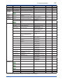
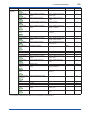
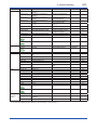
Parameter Summary................................................................................. 5-1
IM 01C25R02-01E
iii
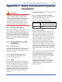
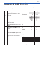
Appendix 1. Safety Instrumented Systems Installation.............................A1-1
A1.1
Scope and Purpose........................................................................................ A1-1
A1.2
Using the EJX for an SIS Application........................................................... A1-1
A1.2.1
Safety Accuracy................................................................................A1-1
A1.2.2
Diagnostic Response Time...............................................................A1-1
A1.2.3
Setup.................................................................................................A1-1
A1.2.4
Required Parameter Settings...........................................................A1-1
A1.2.5
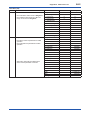
Proof Testing.....................................................................................A1-1
A1.2.6
Repair and Replacement..................................................................A1-2
A1.2.7
Startup Time......................................................................................A1-2
A1.2.8
Firmware Update..............................................................................A1-2
A1.2.9
Reliability Data..................................................................................A1-2
A1.2.10 Lifetime Limits...................................................................................A1-2
A1.2.11 Environmental Limits........................................................................A1-2
A1.2.12 Application Limits..............................................................................A1-2
A1.3
Definitions and Abbreviations....................................................................... A1-3
A1.3.1
Definitions.........................................................................................A1-3
A1.3.2
Abbreviations....................................................................................A1-3
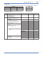
Appendix 2. ILBD Check List.........................................................................A2-1
Revision Information
IM 01C25R02-01E
1.
1-1
<1. Introduction>
Introduction
Thank you for purchasing the DPharp EJX
multivariable transmitter.
EJX multivariable transmitters are precisely
calibrated at the factory before shipment.
To ensure both safety and efficiency, please
read this manual carefully before operating the
instrument.
This manual describes the HART protocol
communication functions of the EJX multivariable
transmitter and explains how to set the parameters
for EJX multivariable transmitters using the HART
configuration tool.
For information on the installation, wiring, and
maintenance of EJX multivariable transmitters,
please refer to the user’s manual.
For information on the flow setup of EJX
multivariable transmitters, please refer to the user’s
manual and FSA120 FieldMate FlowNavigator online manual.
EJX910A / EJX930A
IM 01C25R01-01E
FSA110 / 111 FieldMate Versatile IM 01R01A01-01E
Device Management Wizard
FSA120 FieldMate FlowNavigator IM 01C25R51-01E
• If any question arises or errors are found, or if
any information is missing from this manual,
please inform the nearest Yokogawa sales
office.
• The specifications covered by this manual are
limited to those for the standard type under the
specified model number break-down and do not
cover custom-made instruments.
• Please note that changes in the specifications,
construction, or component parts of the
instrument may not immediately be reflected
in this manual at the time of change, provided
that postponement of revisions will not cause
difficulty to the user from a functional or
performance standpoint.
• The following safety symbols are used in this
manual:
WARNING
Indicates a potentially hazardous situation which,
if not avoided, could result in death or serious
injury.
WARNING
When using the EJX in a Safety Instrumented
Systems (SIS) application, refer to Appendix 1
in this manual. The instructions and procedures
in the appendix must be strictly followed in order
to maintain the designed safety integrity of the
transmitter.
Regarding This Manual
• This manual should be provided to the end
user.
• The contents of this manual are subject to
change without prior notice.
• All rights reserved. No part of this manual may
be reproduced in any form without Yokogawa’s
written permission.
• Yokogawa makes no warranty of any kind with
regard to this manual, including, but not limited
to, implied warranty of merchantability and
fitness for a particular purpose.
CAUTION
Indicates a potentially hazardous situation which,
if not avoided, may result in minor or moderate
injury. It may also be used to alert against unsafe
practices.
IMPORTANT
Indicates that operating the hardware or software
in this manner may damage it or lead to system
failure.
NOTE
Draws attention to information essential for
understanding the operation and features.
IM 01C25R02-01E
1.1 Safe Use of This Product
For the safety of the operator and to protect the
instrument and the system, please be sure to follow
this manual’s safety instructions when handling this
instrument. If these instructions are not heeded,
the protection provided by this instrument may be
impaired. In this case, Yokogawa cannot guarantee
that the instrument can be safely operated. Please
pay special attention to the following points:
(a) Installation
• This instrument may only be installed by an
engineer or technician who has an expert
knowledge of this device. Operators are not
allowed to carry out installation unless they
meet this condition.
• With high process temperatures, care must
be taken not to burn yourself by touching the
instrument or its casing.
• Never loosen the process connector nuts when the
instrument is installed in a process. This can lead
to a sudden, explosive release of process fluids.
• When draining condensate from the pressure
detector section, take appropriate precautions to
prevent the inhalation of harmful vapors and the
contact of toxic process fluids with the skin or eyes.
• When removing the instrument from a
hazardous process, avoid contact with the
process fluid and the interior of the meter.
• All installation shall comply with local installation
requirements and the local electrical code.
(b) Wiring
• The instrument must be installed by an engineer
or technician who has an expert knowledge of
this instrument. Operators are not permitted to
carry out wiring unless they meet this condition.
• Before connecting the power cables, please
confirm that there is no current flowing through
the cables and that the power supply to the
instrument is switched off.
(c) Operation
• Wait 10 min. after the power is turned off before
opening the covers.
(d) Maintenance
• Please carry out only the maintenance
procedures described in this manual. If you
require further assistance, please contact the
nearest Yokogawa office.
• Care should be taken to prevent the build up of dust
or other materials on the display glass and the name
plate. To clean these surfaces, use a soft, dry cloth.
<1. Introduction>
1-2
(e) Modification
• Yokogawa will not be liable for malfunctions or
damage resulting from any modification made
to this instrument by the customer.
1.2 Warranty
• The warranty shall cover the period noted on
the quotation presented to the purchaser at the
time of purchase. Problems occurring during
the warranty period shall basically be repaired
free of charge.
• If any problems are experienced with this
instrument, the customer should contact the
Yokogawa representative from which this
instrument was purchased or the nearest
Yokogawa office.
• If a problem arises with this instrument,
please inform us of the nature of the problem
and the circumstances under which it
developed, including the model specification
and serial number. Any diagrams, data and
other information you can include in your
communication will also be helpful.
• The party responsible for the cost of fixing the
problem shall be determined by Yokogawa
following an investigation conducted by Yokogawa.
• The purchaser shall bear the responsibility for
repair costs, even during the warranty period, if
the malfunction is due to:
- Improper and/or inadequate maintenance by
the purchaser.
- Malfunction or damage due to a failure
to handle, use, or store the instrument in
accordance with the design specifications.
- Use of the product in question in a location
not conforming to the standards specified by
Yokogawa, or due to improper maintenance
of the installation location.
- Failure or damage due to modification or
repair by any party except Yokogawa or an
approved representative of Yokogawa.
- Malfunction or damage from improper
relocation of the product in question after
delivery.
- Reason of force majeure such as fires,
earthquakes, storms/floods, thunder/
lightening, or other natural disasters, or
disturbances, riots, warfare, or radioactive
contamination.
IM 01C25R02-01E
<1. Introduction>
1-3
1.3 ATEX Documentation
This is only applicable to the countries in European Union.
GB
DK
SK
CZ
I
LT
E
LV
NL
EST
PL
SF
SLO
P
H
F
BG
D
RO
S
M
GR
IM 01C25R02-01E
2.
2-1
<2. Connection>
Connection
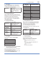
2.1 Integral Indicator Display
When Powering On
NOTE
For models with the integral indicator code “D”, the
display shows all segments in the LCD and then
changes to the displays shown below sequentially.
All segments display
Model name (3 sec.)
LCD display can be set to all segments display
only.
• Procedure to call up the display
[Root Menu] (Refer to subsection
DD (HART 5/7)
3.1.1) → Detailed setup → Display
DTM (HART 7)
condition → Chg power on info
Configuration → Local Display
DTM (HART 5)
→ Chg power on info
Show all segments display, Model
On
name, Communication Protocol, and
Device Revision when powering on.
Show all segments display when
Off
powering on.
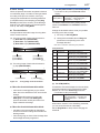
2.2 HART Protocol Revision
Communication Protocol (3 sec.)
Device Revision (3 sec.)
F0200.ai
Either “5” or “7” is displayed on the communication
protocol display as HART protocol revision followed
by device revision number on the device revision
display.
NOTE
For output signal code “E”, this function is
available for software revision 3.01 or later.
Software revision can be checked by the
following procedure.
DD(HART 5)
DTM(HART 5)
[Root Menu](Refer to subsection
3.1.1) → Review → Software rev
Configuration → Device information1
→ Software rev
NOTE
In this User’s Manual, HART protocol revision
5 and 7 are described as HART 5 and HART 7
respectively.
For the models with the output signal code “-J”,
HART protocol revision 5 or 7 is selectable. The
protocol revision is set as specified in the order.
The typical function which is available by HART
protocol revision 7 is listed as follows. Refer to
HART 7 description in this document or HART 7 mark
for detail.
• Long Tag Supporting Up to 32 Characters
Long tag secures a better asset management
with abundant digits in its software.
• Enhanced Burst Mode and Event Notification
Advanced burst mode includes the variety
of transmission setting by specifying burst
variables, update period, and message trigger
mode, and event notification function gives
you alert signal based on the status change in
preset values and self-diagnosis.
• Squawk
Identifying the transmitter by displaying the
particular pattern on LCD
• Multidrop Communication
Up to 63 transmitters can be connected. An
analog signal output available for one device in
a loop.
How to confirm protocol revision is shown below.
There are three ways to confirm the protocol
revision set to the transmitter.
IM 01C25R02-01E
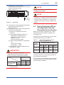
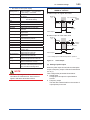
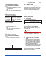
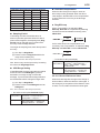
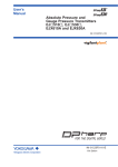
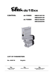
(1) Confirmation by the name plate
The HART protocol revision is shown by the last
number of the serial number.
Refer to Figure 2.1.
STYLE
MODEL
SUFFIX
SUPPLY
OUTPUT
MWP
2-2
<2. Connection>
mA DC
V DC
CAL
RNG
HART 7 communication is supported by
FieldMate R2.02 or later.
NOTE
NO.
Made in Japan
TOKYO 180-8750 JAPAN
: Refer to USER'S MANUAL.
XXX - - - XX
5 : HART 5
7 : HART 7
F0201.ai
Figure 2.1 NOTE
Name Plate
(2) Confirmation by using integral indicator (When
the integral indicator code is “D”)
Refer to section 2.1.
(3) Confirmation by using HART configuration tool
Follow the procedure below.
1) Connect the configuration tool to the
transmitter.
2)-1 When using DD(HART 5/HART 7) or
DTM(HART 7) configuration tool.
Select the “Root Menu” (Refer to
subsection 3.1.1)
Call up the “Review” display.
2)-2 When using DTM(HART 5) configuration
tool.
Call up “HART” display.
Configuration → HART
3) HART protocol revision is displayed on the
“Universal rev” column.
IMPORTANT
Protocol revision supported by HART
configuration tool must be the same or higher
than that of the EJX multivariable transmitter.
Protcol revision
supported by HART
configuration tool
Protocol revision of
EJX multivariable
transmitter
5
7
5
7
×
When the output signal code of EJX multivariable
transmitter is “-J”, HART protocol revision can be
changed. Refer to subsection 3.3.17 about the
procedure of the revision change of HART 5 and
HART 7.
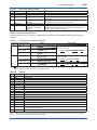
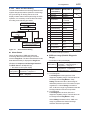
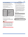
2.3 Device Description (DD) on
a Configuration Tool and
Transmitter Device Revision
Before using a HART configuration tool, confirm
that the DD for the transmitter is installed in the
configuration tool.
About the DD, use the device type, device revision
and DD Revision shown in the Table 2.1.
Table 2.1 HART
Protocol
Revision (*1)
HART Protocol Revision, Device
Revision and DD Revision
EJX Multivariable Transmitter
Model
Name
Device
Type
Device
DD
Revision Revision
5
EJX910A EJX-MV
EJX930A (0x54)
2
2
or later
7
EJX910A EJX-MV
EJX930A (0x3754)
10
1
or later
*1: When the output signal code is “–E”, only “5” is available.
The device revision of the transmitter and DD can
be confirmed as shown below.
If the correct DD is not installed in the configuration
tool, download it from the official web site of HART
Communication Foundation.
: Communication OK
×: Communication NG
IM 01C25R02-01E
(1) Confirming the device revision of the transmitter
● Confirmation by using integral indicator
(When the integral indicator code is “D”)
Refer to the section 2.1
● Confirmation by using HART configuration
tool
Follow the procedure below.
1) Connect the configuration tool to the
transmitter.
2) Select the “Root Menu” (Refer to
subsection 3.1.1)
Call up the “Review” display.
3) The device revision is displayed on the
“Fld dev rev” column.
(2) Confirming the device revision of the
configuration tool
Confirm the device revision from the installed
DD file name according to the procedure
provided for the configuration tool.
The first two digits indicate the device revision
and the next two digits indicate the DD revision.
0 a 0 1. X X X
DD revision
Device revision
NOTE
Device revision of DD file is given in hexadecimal
2.4 Set the parameters using
DTM
HART
Protocol
Revision
5
7
NOTE
The DTM revision can be confirmed by “DTM
setup”.
Device Files is a Media included in FieldMate.
The user registration site provides Device Files
with the latest update programs.
(URL: https://voc.yokogawa.co.jp/PMK/)
In case update, following operation by “DTM
setup” is required.
• Update DTM catalog
• Assign corresponding DTM to the device
(refer to Table 2.2)
Refer to FieldMate Instruction Manual for detail.
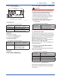
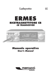
2.5 Interconnection Between
DPharp and the HART
Configuration Tool
The HART configuration tool can interface with the
transmitter from the control room, the transmitter
site, or any other wiring termination point in the
loop, provided there is a minimum of 250 Ω
between the connection and the power supply. To
communicate, it must be connected in parallel with
the transmitter; the connections are non-polarized.
Figure 2.2 illustrates the wiring connections for
direct interface at the transmitter site for the
DPharp. The HART configuration tool can be used
for remote access from any terminal strip as well.
Control room
When configure the parameters using FieldMate,
use the DTM (Device Type Manager) shown in the
Table 2.2.
Table 2.2
2-3
<2. Connection>
DPharp
HART Protocol Revision and DTM
DTM
Name
Revision
EJX910
V2.1
1.4.160.27*1 EJX910A
or later
EJX930A
EJX910
HART 7
DTM
3.3.0.112*2
or later
EJX910A
EJX930A
Device
Type
Device
Revision
EJX910
(0x54)
2
EJX910_
EXP
(0x3754)
10
Terminal
board Distributor
USB
FieldMate
Modem
EJX multivariable transmitters
Model
Name
Relaying
terminals
USB
PC/FieldMate
HART configuration tool
Figure 2.2
F0202.ai
Connecting the HART Configuration
Tool
*1: The DTM corresponding to this revision is included in
Yokogawa DTM Library HART 2011-3/Device Files R3.03.00
*2: The DTM corresponding to this revision is included in
Yokogawa Device DTM Library 2.0/Device Files R3.03.00
IM 01C25R02-01E
<2. Connection>
2-4
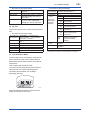
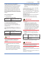
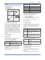
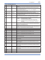
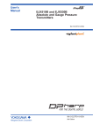
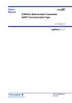
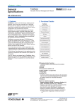
2.6 Power Supply Voltage and
Load Resistance
When configuring the loop, make sure that the
external load resistance is within the range in the
figure below.
(Note)With an intrinsically safe transmitter, external load
resistance includes safety barrier resistance.
600
External
load
resistance
R (Ω)
R=
E–10.5
0.0244
Communication
applicable range
250
0
10.5
16.6
25.2
Power supply voltage E (V DC)
Figure 2.3
42
F0203.ai
Relationship between Power Supply
Voltage and External Load Resistance
IM 01C25R02-01E
3.
<3. Parameter Setting>
3-1
Parameter Setting
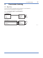
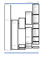
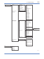
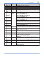
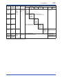
3.1 Menu Tree
The menu tree is different in DD(HART 5/HART 7)/DTM(HART 7) and DTM(HART 5).
See the menu tree corresponding to the configuration tool.
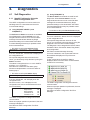
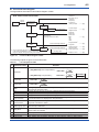
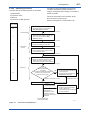
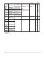
3.1.1 For DD (HART 5/HART 7) and DTM (HART 7)
■ DD (HART 5/HART 7)
Root Menu
• Device setup
• PV
• PV AO
• PV LRV
• PV URV
• Process variables
• Diag/Service
• Basic setup
• Detailed setup
• Review
A
B
C
D, E
• Basic setup
• Detailed setup
• Review
• Diag/Service
• Process variables
C
D, E
■ DTM (HART 7)
Root Menu
• Device Configuration - Configure/Setup
• Diagnostic
• Process Variable
B
A
F0301-01.ai
IM 01C25R02-01E
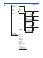
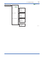
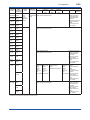
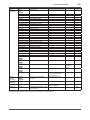
A
• Process variables
3-2
<3. Parameter Setting>
HART 5
HART 7
• PV
• PV % (DD)
% Range (DTM)
• PV AO (DD)
Loop Current (DTM)
• Engr Disp
• Engr exp
• Engr Unit
• View fld dev vars
• Flow
• Pres
• SP
• ET
• Total Flow
• Cap temp
• Amp temp
• Output vars
• Device Variables
and Status HART 7
: HART 5 only
: HART 7 only
• PV
• PV is
• Change PV Assgn
• PV
• PV Unit
• PV Data Quality HART 7
• PV Limit Status HART 7
• Flow
• Pres
• SP
• ET
• SV
• SV is
• Change SV Assgn
• SV
• SV Unit
• SV Data Quality HART 7
• SV Limit Status HART 7
• Flow
• Pres
• SP
• ET
• Total Flow
• TV
• TV is
• Change TV Assgn
• TV
• TV Unit
• TV Data Quality HART 7
• TV Limit Status HART 7
• Flow
• Pres
• SP
• ET
• Total Flow
• 4V
• QV
• 4V(QV) is
• Change 4V(QV)
Assgn
• 4V(QV)
• 4V(QV) Unit
• QV Data Quality
• QV Limit Status
• Flow
• Pres
• SP
• ET
• Total Flow
HART 5
HART 7
HART 7
HART 7
• Flow
• Flow Data Quality
• Flow Limit Status
• Pres
• Pres Data Quality
• Pres Limit Status
• SP
• SP Data Quality
• SP Limit Status
• ET
• ET Data Quality
• ET Limit Status
• Total Flow
• Total Flow Data Quality
• Total Flow Limit Status
• % Range
• % Range Data Quality
• % Range Limit Status
• Loop Current
• Loop Current Data Quality
• Loop Current Limit Status
F0301-02.ai
IM 01C25R02-01E
<3. Parameter Setting>
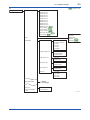
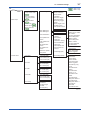
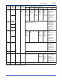
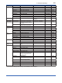
B
• Diag/Service
HART 7
• Status
• Status group 1
• Status group 2
• Status group 3
• Status group 4
• Status group 5
• Status group 6
• Status group 7
• Status group 8
• Status group 9
• Status group 10
• Status group 11 HART 7
• Device status HART 7
• Ext dev status HART 7
• Cfg chng count HART 7
• Reset Cfg chng flag HART 7
• Time Stamp HART 7
• Test
• Calibration
• Diag Parameters
• Error log
• Test Auto Release
Time
• Keypad input
• PV is
• Change PV Assgn
• PV Unit
• PV LRV
• PV URV
• PV Damp
• Analog output trim
• D/A trim
• Scaled D/A trim
• Clear D/A trim
• Pres sensor trim
• Pres trim
• Clear P trim
• SP sensor trim
• SP trim
• Clear SP trim
• ET sensor trim
• ET trim
• Clear ET trim
• Trim info.
• Trim Who
• Trim Date
• Trim Loc
• Trim Desc
3-3
: HART 7 only
• Loop test
• Self test
• Master test
• Squawk HART 7
• Simulate HART 7
See B1
(next page)
• Error log view
• Error log Clear
F0301-03.ai
IM 01C25R02-01E
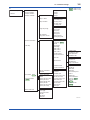
• Diag Mode
• Diag Applicable
• Diag Variables
• Diag Description
• Ref fDP Status
• Ref fDP
• Ref fSPl Status
• Ref fSPl
• Ref fSPh Status
• Ref fSPh
• Ref BlkF Status
• Ref BlkF
• Ref DP Avg Status
• Ref DP Avg
• Fluct Variables
• fDP Status
• fDP
• fSPl Status
• fSPl
• fSPh Status
• fSPh
B1
• Diag Error
• Diag Option
• ILBD Parameters
• Configuration
• Diag Output
• Set Diag Mode
• Diag Period
• Diag Lim
• Lim fDPmax
• Lim fDPmin
• Lim fSPlmax
• Lim fSPlmin
• Lim fSPhmax
• Lim fSPhmin
• Lim BlkFmax
• Lim BlkFmin
• Lim DPAvgmax
• Lim DPAvgmin
• Diag Reference
• Diag Supp Count
• Diag Description
• Ref fDP
• Ref fSPl
• Ref fSPh
• Ref BlkF
• Ref DP Avg
• Diag Ref Lim
• Diag DPComp
• Ref Lim fDPmin
• Ref Lim fSPmin
• Ref Lim BlkFmax
• Status
• Cap temp
• Amp temp
• Flg temp
• Configuration
• Flg temp Coef
• Flg temp Lim
• HT Parameters
• Ratio fDP Status
• Ratio fDP
• Ratio fSPl Status
• Ratio fSPl
• Ratio fSPh Status
• Ratio fSPh
• BlkF Status
• BlkF
• DP Avg Status
• DP Avg
• CRatio fDP Status
• CRatio fDP
• NRatio fDP Status
• NRatio fDP
• Diag Reference
• Status
• Diag Parameters
3-4
<3. Parameter Setting>
• Flg temp Hi Alert Val
• Flg temp Lo Alert Val
• Diag Out Option
• Diag Fixed Out Val
F0301-04.ai
IM 01C25R02-01E
<3. Parameter Setting>
C
• Basic setup
HART 7
3-5
: HART 7 only
• Tag
• Long tag
HART 7
• Units
• Pres Unit
• SP Unit
• ET Unit
• Flow Unit
• Total Flow Unit
• Keypad input
• PV is
• Change PV Assgn
• PV Unit
• PV LRV
• PV URV
• PV Damp
• Device infomation
• Date
• Descriptor
• Message
• Write Protect
• Model
• Others
• Low cut
• Low cut mode
• H/L Swap
F0301-05.ai
IM 01C25R02-01E
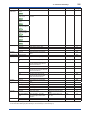
D
• Detailed setup
3-6
<3. Parameter Setting>
HART 5
• Sensors
• Review
• Signal condition
• Pres
• SP
• Cap temp
• Amp temp
• ET
• Flow Setup
HART 7
• Flow LRV
• Flow URV
• Flow Unit
• Flow Damp
• DP Setup (DD)
Pres Setup (DTM)
• SP Setup
• ET Setup
• Total Flow
• Others (DD)
• Output condition
• ET LRV
• ET URV
• ET Unit
• ET LSL
• ET USL
• ET Min span
• ET Damp
• Fixed ET
• Total Flow
• Total Flow Unit
• Pulse rate
• Freq at 100%
• Total Flow Mode
• Config User Unit
• Low cut
• Low cut mode
• H/L Swap
• Process variables
• Analog output
• Loop test
• Loop current mode
HART 7
See D1
(next page)
• Display condition
• Device information
• Test Key
• Simulation HART 5
• Flow Simulation
See E
• D/A trim
• Scaled D/A trim
• Clear D/A trim
• AO alm typ
• Channel flags HART 7
• Auto recover
• AO lower limit
• AO upper limit
: HART 5 only
: HART 7 only
• Pres LRV
• Pres URV
• Pres Unit
• Pres LSL
• Pres USL
• Pres Min span
• Pres Damp
• Low Cut (DTM)
• Low Cut mode(DTM)
• H/L Swap (DTM)
• SP LRV
• SP URV
• SP Unit
• SP LSL
• SP USL
• SP Min span
• SP Damp
• A/G Select
• SP H/L Select
• Atm. Pres Value
• Auto Atm. Pres
• ET Fixed
• Fixed ET Val
• Cvt Val
• Set Base Unit
• Modify Unit
• PV
• PV % (DD)
% Range (DTM)
• PV AO (DD)
Loop Current (DTM)
• Engr Disp
• Engr exp
• Engr Unit
• Digital Output
HART 7
• Basic Flow Calc
F0301-06.ai
IM 01C25R02-01E
<3. Parameter Setting>
D1
HART 5
HART 7
• Poll addr
• Loop current mode
• Burst Message 1
HART 7
• Num req preams
• num resp preams
• HART output
HART 7
• Burst Condition
HART 7
• Burst mode HART 5
• Burst option HART 5
• Burst Xmtr Vals
• Burst Mode
• Burst Command
• Burst Device
Variables
• Set Burst Trigger
• Set Burst Period
• Burst Msg Trigger
Mode
• Burst Trigger Level
• Update Period
• Max Update Period
3-7
: HART 5 only
: HART 7 only
• Burst Variable Code
HART 5
• Burst Message 2
• Burst Message 3
Same as above
Same as above
• Event Notification
• Event Notification
Control
• Event Mask
• Set Event
Notification Timing
• Event Notification
Retry Time
• Max Update Time
• Event Debounce
Interval
• Flow Update time
period
• Pres Update time
period
• SP Update time
period
• ET Update time
period
• Total Flow Update
time period
• Process Alerts
• Pres Alert
• Pres Alert Mode
• Pres Hi Alert (Val)
• Pres Lo Alert (Val)
• SP Alert
• SP Alert Mode
• SP Hi Alert (Val)
• SP Lo Alert (Val)
• ET Alert
• ET Alert Mode
• ET Hi Alert (Val)
• ET Lo Alert (Val)
• Flow Alert
• Flow Alert Mode
• Flow Hi Alert (Val)
• Flow Lo Alert (Val)
• DO Config
• Digital Output
• DO Select
• DO Signal type
• DO Test
• DO Frequency
• Knowledge (DD)
Knowledge (DTM)
• Device Status Mask
• Status group 1 Mask
to 11 Mask
• Ext dev status Mask
• Device Diagnostic
Status 0 Mask
• Device Diagnostic
Status 1 Mask
• AO saturated Mask
• AO fixed Mask
• Event Status
• Time First Unack
Event Triggered
• Acknowledge Event
Notificatoin
• Event Status
• Event Number
• Time First Unack
Event Triggered
• Latched Cfg chng
count
• Latched Device
Status
• Latched Status
group 1 to 11
• Latched Ext dev
status
• Latched Device
Diagnostic Status 0
• Latched Device
Diagnostic Status 1
• Latched AO
saturated
• Latched AO fixed
F0301-07.ai
IM 01C25R02-01E
HART 5
E
• Detailed setup
• Review
3-8
<3. Parameter Setting>
• Sensors
• Signal condition
• Output condition
• Display condition
• Disp select
• Disp % Reso
• Disp condition
• Engr disp range
• Bar Indicator
• Chg power on info
• Device information
• Field device info
• Test Key
• Disp1
• Disp2
• Disp3
• Disp4
• Engr LRV
• Engr URV
• Engr exp
• Engr Unit
• Engr point
• Set Engr Unit
• Modify Engr Unit
• Tag
• Long tag HART 7
• Date
• Descriptor
• Message
• MS Code 1
• MS Code 2
• MS Code 3
• Write Protect
• Wrt protect menu
• Revision #’s
• Additional Info
• Option Password
• Simulation
HART 5
• Flow Simulation
HART 7
• Basic Flow Calc
• (Flow) Simulation
Mode
• (Flow) Sim Pres Unit
• (Flow) Sim Pres
• (Flow) Sim SP Unit
• (Flow) Sim SP
• (Flow) Sim Temp Unit
• (Flow) Sim Temp
• Flow Calc mode
• Fluid Type
• Flow Calc Fixed
• Ref SP
• Ref Temp
• Temp K1
: HART 5 only
: HART 7 only
• Flow disp point
• Pres disp point
• SP disp point
• ET disp point
• TF disp point
• Ext SW
• Sensor infomation
• Self test
HART 7
• Isoltr matl
• Fill fluid
• Gasket matl
• Process Conn matl
• Drain vent matl
• Process Conn type
• RS Isoltr matl
• Process Conn size
• Num of RS
• RS fill fluid
• RS type
• Write protect
• Enable wrt 10min
• New password
• Software seal
• Universal rev
• Fld dev rev
• Software rev
• Chg universal rev
• Style No.
• Serial No.
• Mftr Date
• Extra No.
• Final asmbly num
• Dev id
• Distributor
• PT100 Serial No.
• Country HART 7
• Max dev vars
HART 7
• Device Profile
HART 7
F0301-08.ai
IM 01C25R02-01E
<3. Parameter Setting>
3-9
3.1.2 For DTM (HART 5)
Root Menu
• Process Variables
• Device Status
• Diag and Service
• Easy Setup
• Configuration
• Calibration
• Write Protect
P
Q
R
S
T
U
V
P
• Process Variables
• PV %
• PV AO
• PV URV
• PV LRV
• PV Damp
• Pres
• SP
• A/G Select
• ET
• Flow
• Total Flow
• Engr Disp
• Engr exp
• Engr Unit
Q
• Device Status
• Process Variable
• PV %
• PV is
• Pres
• SP
• ET
• Flow
• Diagnostic List
• Device Status
• Hardware Failure
• Transducer Status
• Diag Status
• Configuration
F0301-09.ai
IM 01C25R02-01E
<3. Parameter Setting>
3-10
R
• Diag and Service
• Service
• Loop test
• Master Test
• DO Test
• Error log view
• Error log Clear
• Test Key
• Test Auto Release
Time
• BlkF
• fDP
• fSPh
• fSPl
• DPAvg
• Diag Description
• Ref BlkF
• Ref fDP
• Ref fSPh
• Ref fSPl
• Ref DPAvg
• CRatio fDP
• NRatio fDP
• Ratio fDP
• Ratio fSPh
• Ratio fSPl
• Cap Temp
• Amp Temp
• Flg Temp
• Impulse Line
Blockage Detection
• Diag Mode
• Diag Period
• Diag DPComp
• Diag Description
• Ref BlkF
• Ref fDP
• Ref fSPh
• Ref fSPl
• Ref DPAvg
• Alarm Notification
(Diag Option)
• Threshold
• Advanced Diag
Variables
• Advanced Diag
Configurations
• Advanced Diag
Alerts
S
• Easy Setup
• Heat Trace
• Alarm Notification
(Diag Option)
• Threshold
• Flg Temp
Coefficient
• Tuning
• Flg Temp
• Diag Output
• Diag Out Option
• Diag Fixed Out Val
• Diag Error
• Related to high side
alarm
• Related to both side
alarm
• Related to low side
alarm
• Related to Flg temp
alarm
• Diag Suppress Count
• Sensitivity
• Tag
• PV Unit
• PV URV
• PV LRV
• PV Damp
F0301-10.ai
IM 01C25R02-01E
3-11
<3. Parameter Setting>
T
• Configuration
• Pressure Sensor
• Static Pressure
Sensor
• External
Temperature Sensor
• ET USL
• ET LSL
• ET Min Span
• ET Unit
• ET URV
• ET LRV
• ET Damp
• ET Fixed
• Fixed ET Val
• SP USL
• SP LSL
• SP Min span
• SP Unit
• SP URV
• SP LRV
• SP Damp
• SP H/L Select
• A/G Select
• Atm. Pres Value
• Auto Atm. Pres
• Flow
• Total Flow
• Physical Information
• Process Conn type
• Process Conn matl
• Process Conn size
• Gasket matl
• Isoltr matl
• Drain vent matl
• Fill fluid
• RS type
• RS isoltr matl
• RS fill fluid
• Num of RS
• Total Flow Unit
• Total Flow Mode
• Conf User Unit Cvt
Val
• Conf User Unit Set
Base Unit
• Conf User Unit
Modify Unit
• DO Frequency
• DO Signal type
• Pulse rate
• Freq at 100%
• Process Input
• Analog Output
• Output Variables
• PV is
• Change PV Assgn
• PV
• SV is
• Change SV Assgn
• SV
• TV is
• Change TV Assgn
• TV
• 4V is
• Change 4V Assgn
• 4V
• PV is
• PV %
• PV AO
• PV Unit
• PV URV
• PV LRV
• PV Damp
• Low cut
• Low cut mode
• AO alm typ
• AO upper limit
• AO lower limit
• Pres USL
• Pres LSL
• Pres Min span
• Pres Unit
• Pres URV
• Pres LRV
• Pres Damp
• Low cut
• Low cut mode
• H/L Swap
• Flow Unit
• Flow URV
• Flow LRV
• Flow Damp
• Pres
• Pres Unit
• SP
• SP Unit
• A/G Select
• ET
• ET Unit
• Flow
• Flow Unit
• Cap temp
• Amp temp
F0301-11.ai
See T1
(next page)
IM 01C25R02-01E
<3. Parameter Setting>
3-12
T1
• Configuration
• Local Display
• Process Alerts
• Device Information1
• Model
• Manufacturer
• Hardware rev
• Software rev
• Date
• Descriptor
• Message
• Final asmbly num
• Auto recover
• Ext SW
• Pres Alert mode
• Pres Hi Alert Val
• Pres Lo Alert Val
• SP Alert Mode
• SP Hi Alert Val
• SP Lo Alert Val
• ET Alert Mode
• ET Hi Alert Val
• ET Lo Alert Val
• Flow Alert Mode
• Flow Hi Alert Val
• Flow Lo Alert Val
• Digital Output
• DO Select
• DO Signal type
• Device Information2
• HART
• Simulation
• Simulation Mode
• Sim Pres Unit
• Sim Pres
• Sim SP Unit
• Sim SP
• Sim Temp Unit
• Sim Temp
• Basic Flow Calc
• Tag
• Poll addr
• Dev id
• Universal rev
• Fld dev rev
• Chg universal rev
• Num req preams
• Physical signal code
• Burst mode
• Burst option
• Burst Xmtr Vals
• Disp Out1
• Disp Out2
• Disp Out3
• Disp Out4
• Disp % Reso
• Pres disp point
• SP disp point
• ET disp point
• Flow disp point
• TF disp point
• Engr URV
• Engr LRV
• Engr Unit
• Engr exp
• Engr point
• Bar Indicator
• Chg power on info
• Model 1
• Model 2
• Model 3
• Style No.
• Serial No.
• Mftr Date
• Extra No.
• PT100 Serial No.
• Option Password
• Flow Calc Mode
• Fluid Type
• Flow Calc Fixed
• Ref SP
• Ref Temp
• Temp K1
U
• Calibration
• Trim Who
• Trim Date
• Trim Loc
• Trim Desc
• Pressure trim
• Clear Pressure Sensor trim
• Static Pressure trim
• Clear Static Pressure Sensor trim
• External Temp trim
• Clear External Temp Sensor trim
• D/A trim
• Scaled D/A trim
• Clear D/A trim
V
• Write Protect
• Write Protect
• Enter new password
F0301-12.ai
IM 01C25R02-01E
3.2 Basic Setup
*1: The characters bounded by the thick line in the following table
can be used.
*2: All characters in the following table can be used.
IMPORTANT
After setting and sending data with the HART
configuration tool, wait 30 seconds before
turning off the transmitter. If it is turned off
too soon, the settings will not be stored in the
transmitter.
3.2.1 Tag and Device Information
If there are specified when ordering, the desired Tag
No. and device information are set and shipped.
Tag No. and device information can be checked as
follows.
• Procedure to call up the display using DD
(HART 5/HART 7) and DTM (HART 7)
Item
Tag
Long Tag
(HART 7 only)
Descriptor
Message
Date
Procedure
[Root Menu] → Basic setup → Tag
[Root Menu] → Basic setup → Long
Tag
[Root Menu] → Basic setup → Device
information → Descriptor
[Root Menu] → Basic setup → Device
information → Message
[Root Menu] → Basic setup → Device
information → Date
• Procedure to call up the display using DTM
(HART 5)
Tag
Item
Descriptor
Message
Date
Procedure
Easy Setup → Tag
or Configuration → HART → Tag
Configuration → Device information 1
→ Descriptor
Configuration → Device information 1
→ Message
Configuration → Device information 1
→ Date
When the Tag No. and device information are
changed, input them based on the following
limitations.
Item
Tag
3-13
<3. Parameter Setting>
SP
!
"
#
$
%
&
'
(
)
*
+
,
-
.
/
0
1
2
3
4
5
6
7
8
9
:
;
<
=
>
?
O
@
A
B
C
D
E
F
G
H
I
J
K
L
M
N
P
Q
R
S
T
U
V
W
X
Y
Z
[
\
]
^
_
`
a
b
c
d
e
f
g
h
i
j
k
l
m
n
o
p
q
r
s
t
u
v
w
x
y
z
{
|
}
~
*: SP shows one-byte space
3.2.2 Process Variable Setup
The multivariable transmitter can handle five kinds
of Device Variables; differential pressure (DP),
static pressure (SP), external temperature (ET), and
also flow rate and total flow which are calculated by
using these values.
Four data selected from these five data can be
assigned to Dynamic Variables; PV (Primary
Variable), SV (Secondary Variable), TV (Tertiary
Variable) and 4V* (Fourth Variable) or QV*
(Quaternary Variable).
Data assigned for PV become the 4 to 20mA
current output.
Total flow can not be assigned to PV.
These data are set as follows when the instrument
is shipped.
In case of measurement function code is “A” (Multi
sensing):
PV: Differential pressure
SV: Static pressure
TV: External temperature
4V/QV*: Flow rate
In case of measurement function code is “B” (Mass
flow measurement):
PV: Flow rate
SV: Differential pressure
TV: Static pressure
4V/QV*: External temperature
*: 4V is for HART 5, QV is for HART 7
Limitations
Up to 8 characters or numbers*1
Long tag
Up to 32 characters or numbers*2
(HART 7 only)
Descriptor
Up to 16 characters or numbers*1
Message
Up to 32 characters or numbers*1
Date
mm/dd/yyyy
- mm: month (2 digits)
- dd: days (2 digits)
- yyyy: years (4 digits)
IM 01C25R02-01E
<3. Parameter Setting>
• Procedure to call up the display using DD
(HART 5/HART 7) and DTM (HART 7)
PV related
parameter
→ PV is
→ Change PV
Assgn
SV related
parameter
→ SV is
→ Change SV
Assgn
TV related
parameter
→ TV is
→ Change TV
Assgn
4V/QV related
parameter
→ 4V is / QV is
→ Change
4V Assgn
/Change QV
Assgn
[Root Menu] → Process variables →
Output vars → PV →
Current PV value
Select the variable assigned to PV
(Flow, Pres, SP, ET)
[Root Menu] → Process variables →
Output vars → SV →
Current SV value
Select the variable assigned to SV
(Flow, Pres, SP, ET, Total Flow)
[Root Menu] → Process variables →
Output vars → TV →
Current TV value
Select the variable assigned to TV
(Flow, Pres, SP, ET, Total Flow)
[Root Menu] → Process variables →
Output vars → 4V/QV →
Current 4V/QV value
Select the variable assigned to 4V/QV
(Flow, Pres, SP, ET, Total Flow)
• Procedure to call up the display using DTM
(HART 5)
PV related item Configuration → Output Variables →
→ PV is
Current PV value
→ Change PV Select the variable assigned to PV
Assgn
(Flow, Pres, SP, ET)
It is similar about SV, TV and 4V.
The process variables that can be assigned are Flow,
Pres, SP, ET, and Total Flow.
3.2.3 Measuring Range
This section shows how to confirm and change
the parameters for measuring range of flow rate,
differential pressure, static pressure, external
temperature, and total flow, and also unit and
damping time constant.
These parameters are set at the factory before
shipment if specified at the time of order.
Follow the procedure below to change them.
About the differential pressure, static pressure and
external temperature, settable range are shown
on the parameters of LSL (Lower settable limit),
USL (Upper settable limit) and Min span (Minimum
span). Set the data within the range.
3-14
• Procedure to call up the display
Call up and setting of flow related parameters
DD (HART 5/7) [Root Menu] → Detailed setup →
DTM (HART 7) Signal condition → Flow Setup →
DTM (HART 5) Configuration → Flow →
→ Flow LRV
Lower range value for flow
→ Flow URV
Upper range value for flow
→ Flow Unit
Unit for flow
→ Flow Damp Damping time constant for flow
Call up and setting of differential pressure related
parameters
DD (HART 5/7) [Root Menu] → Detailed setup →
DTM (HART 7) Signal condition → DP Setup (or Pres
Setup) →
DTM (HART 5) Configuration → Pressure Sensor →
→ Pres LRV
Lower range value for differential
pressure
→ Pres URV
Upper range value for differential
pressure
→ Pres Unit
Unit for differential pressure
→ Pres Damp Damping time constant for differential
pressure
Call up and setting of static pressure related
parameters
DD (HART 5/7) [Root Menu] → Detailed setup →
DTM (HART 7) Signal condition → SP Setup →
DTM (HART 5) Configuration → Static Pressure
Sensor →
→ SP LRV
Lower range value for static pressure
→ SP URV
Upper range value for static pressure
→ SP Unit
Unit for static pressure
→ SP Damp
Damping time constant for static
pressure
Call up and setting of external temperature related
parameters
DD (HART 5/7) [Root Menu] → Detailed setup →
DTM (HART 7) Signal condition → ET Setup →
DTM (HART 5) Configuration → External
Temperature Sensor →
→ ET LRV
Lower range value for external
temperature
→ ET URV
Upper range value for external
temperature
→ ET Unit
Unit for external temperature
→ ET Damp
Damping time constant for external
temperature
Call up and setting of total flow related parameters
DD (HART 5/7) [Root Menu] → Detailed setup →
DTM (HART 7) Signal condition → Total Flow →
DTM (HART 5) Configuration → Total Flow →
→ Total Flow
Unit for total flow
Unit
IM 01C25R02-01E
NOTE
(4) Unit list of flow
Mass Flow
The calibration range can be set as PV LRV >
PV URV under the following conditions,
reversing the 4 to 20 mA output signal.
PV LSL -10% of USL ≤ PV LRV ≤ PV USL
+10% of USL
PV LSL -10% of USL ≤ PV URV ≤ PV USL
+10% of USL
|PV URV - PV LRV| ≥ PV Min. Span
If PV is flow, PV LRV and PV URV must be the
following conditions.
0 ≤ PV LRV
0 ≤ PV URV
PV LRV < PV URV
3-15
<3. Parameter Setting>
Normal/
Standard
Volume
Flow
Volume
Flow
g/s, g/min, g/h, kg/s, kg/min, kg/h,
kg/d, t/min, t/h, t/d, lb/s, lb/min, lb/h,
lb/d, STon/min, STon/h, STon/d,
LTon/h, LTon/d
Nm3/h, NL/h, SL/h, SL/min, SL/s,
Nm3/d, SCFD, SCFH, SCFM, SCFS,
Sm3/d, Sm3/h, MSCFD, MMSCFD
CFM, GPM, L/min, Impgal/min, m3/h,
gal/s, Mgal/d, L/s, ML/d, CFS, ft3/d,
m3/s, m3/d, Impgal/h, Impgal/d, CFH,
m3/min, bbl/s, bbl/min, bbl/h, bbl/d,
gal/h, Impgal/s, L/h, gal/d
(5) Unit list of total flow
g, kg, t, lb, Ston, Lton, oz, gal, L, Impgal, m3,
bbl, yd3, ft3, in3, Nm3, NL, SCF, Spcl*
The flow range is set to LRV=0 and URV=100
when the Flow calc mode is changed to Basic
mode or Full Auto mode.
If PV is ET, PV LRV and PV URV must be the
following conditions.
-210°C ≤ PV LRV ≤ 860°C
(-346°F ≤ PV LRV ≤ 1580°F)
-210°C ≤ PV URV ≤ 860°C
(-346°F ≤ PV URV ≤ 1580°F)
|PV URV - PV LRV| ≥ PV Min. Span
Any number from 0.00 to 100.00 can be set for
the amplifier damping time constant of process
variables.
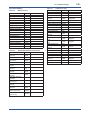
3.2.4 Units
Refer to the subsection 3.2.3 to call up the display.
Select the unit from displayed list as shown below.
(1) Unit list of differential pressure
mmH2O, mmH2O@68degF, mmHg, Torr, MPa,
kPa , Pa, mbar , bar , gf/cm2, kgf/cm2, inH2O,
inH2O@68degF, inHg, ftH2O, ftH2O@68degF, psi,
atm, hPa
Note that the Yokogawa default setting for the
standard temperature is 4°C (39.2°F). For the units
of mmH2O, inH2O, and ftH2O, the pressure varies
according to the standard temperature definition.
Select the appropriate unit with @68degF when a
standard temperature of 20°C (68°F) is required.
(2) Unit list of static pressure
mmH2O, mmH2O@68degF, mmHg, Torr, MPa,
kPa , Pa, mbar , bar , gf/cm2, kgf/cm2, inH2O,
inH2O@68degF, inHg, ftH2O, ftH2O@68degF, psi,
atm, hPa
(3) Unit list of temperature
degC , degF, Kelvin*
* The user unit is displayed on LCD.
To configure the user unit, refer to subsection 3.3.5.
3.2.5 Damping Time Constant Setup
Refer to subsection 3.2.3 to call up the display.
Damping time constant is set as shown in the
following table at the factory when the instrument
is shipped, but in case of the option code /CA is
specified, the damping time constant is set as
specified in the order.
Process variables
Factory default value
Differential pressure
2sec
Static pressure
1sec
External temperature
2sec
Flow rate
0sec
NOTE
• When the HART communication is used
under the condition of quick output change,
set the damping time constant more than 0.5
sec.
• The damping time constant for the amplifier
assembly can be set here. The damping time
constant for the entire transmitter is the sum
of the values for the amplifier assembly and
the capsule assembly.
About the value for the capsule assembly,
refer to the User’s Manual for EJX910/
EJX930 (IM 01C25R01-01E) or General
Specifications (GS 01C25R01-01EN, GS
01C25R04-01EN).
*: In the case of using DTM(HART 7), it is displayed as “K“.
IM 01C25R02-01E
<3. Parameter Setting>
3-16
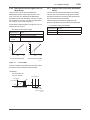
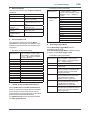
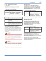
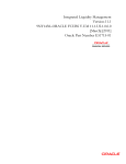
3.2.6 Differential Pressure Signal Low Cut
Mode Setup
3.2.7 Impulse Line Connection Orientation
Setup
Low cut mode can be used to stabilize the
differential pressure output signal near the zero
point. The Low cut is applied to the differential
pressure used to flow calculation. The low cut point
can be set from 0 to 20% of output. (Hysteresis for
the cut point: ±10% of the cut point )
This function reverses the impulse line orientation.
This function is used when the high pressure side
impulse line and the low pressure side impulse line
are connected reverse by mistake.
Follow the procedure below to change the Low cut
mode and Low cut point.
• Procedure to call up the display
DD (HART 5/7)
DTM (HART 7)
DTM (HART 5)
→ Low cut
→ Low cut
mode
[Root Menu] → Basic setup →
Others →
Configuration → Analog Output →
Set from 0 to 20% of output
Select “On” or “Off”
• Procedure to call up the display
DD (HART 5/7)
DTM (HART 7)
DTM (HART 5)
→ H/L Swap
[Root Menu] → Basic setup →
Others →
Configuration → Pressure Sensor →
Select “Normal” or “Reverse”
(%)
50
DP Output
DP Output
(%)
50
Follow the procedure below to assign the high
pressure impulse line to the L side of the transmitter.
20
0
Input
50
(%)
For low cut in Off mode
20
0
Input
50
(%)
For low cut in On mode
F0302.ai
Figure 3.1
Low Cut Mode
The low cut point has hysteresis so that the output
around the point is behaved as below figure.
<Example>
Low cut mode: On
Low cut: 20.00%
Low cut point
DP Output
7.2mA(20%)
4mA
Setting range: 0 to 20%
Input
2%
2%
Hysteresis
fixed at 10%
of the cut point
F0303.ai
IM 01C25R02-01E
3.3
3-17
<3. Parameter Setting>
Detailed Setup
• Procedure to call up the display
3.3.1 Analog Output Signal Adjustable
Range
Output signal adjustable range at normal operating
condition are set as shown below at the factory
when the instrument is shipped, and output signal
are limited by these value.
Standard
Option code /C1
Option code /C2 and /C3
Lower limit
Upper limit
3.8 mA
21.6 mA
3.8 mA
20.5 mA
Output signal range can be changed between
3.8mA and 21.6mA to match it to the equipment on
the receiving side.
Lower value is set at AO lower limit and upper
value is set at AO upper limit respectively.
Follow the procedure below to change the upper
and lower values.
• Procedure to call up the display
DD (HART 5/7)
DTM (HART 7)
DTM (HART 5)
→ AO lower
limit
→ AO upper
limit
[Root Menu] → Detailed setup →
Output condition → Analog output →
Configuration → Analog output →
Set the lower value (mA)
Set the upper value (mA)
Set the values as below.
Lower value < Upper value
3.3.2 Static Pressure Setup
(1) Selection of Gauge pressure and Absolute
pressure
Either the gauge pressure or absolute pressure can
be selected to display on the LCD display.
Absolute pressure is selected when the instrument
is shipped.
DD (HART 5/7) [Root Menu] → Detailed setup →
DTM (HART 7) Signal condition → SP Setup →
DTM (HART 5) Configuration → Static Pressure
Sensor →
→ SP H/L
Select “High” or “Low”
Select
3.3.3 External Temperature Fixation Mode
The external temperature can be fixed with this
mode. The parameter setting to enter the Fixation
Mode when the RTD sensor is disconnected is also
possible.
• Procedure to call up the display
DD (HART 5/7) [Root Menu] → Detailed setup →
DTM (HART 7) Signal condition → ET Setup → Fixed
ET →
DTM (HART 5) Configuration → External
Temperature Sensor →
→ ET Fixed
Select “No”, “Yes” or “FALL BACK”
No: Shows process temperature
value
Yes: Fix the temperature value
FALL BACK: Fix the temperature
value when the RTD
sensor is disconnected.
→ Fixed ET
Set the fixed temperature value
Val
3.3.4 Integral Indicator Scale Setup
The following seven displays are available for
integral indicator. A cycle of up to four displays can
be shown by assigning variables to the parameters
at Disp select.
•
•
•
•
•
•
•
% of PV range
Flow rate
Input differential pressure
Input static pressure
Input external temperature
User set scaled PV
Total flow
• Procedure to call up the display
DD (HART 5/7) [Root Menu] → Detailed setup →
DTM (HART 7) Signal condition → SP Setup →
DTM (HART 5) Configuration → Static Pressure
Sensor →
→ A / G Select Select “Gauge” or “Absolute”
(2) Selection of pressure side
Either the high or low pressure side of capsule can
be selected to monitor the static pressure.
High pressure side is selected when the instrument
is shipped.
IM 01C25R02-01E
<3. Parameter Setting>
Available displays Description and related parameters
% of PV range
(PV %)
F
Flow rate
(Flow)
F
Indicates input value depending on
the set PV range (PV LRV and PV
URV).
PV %
Indicates values of calculated flow
with the indication limits –99999 to
99999.
Flow
Input differential
pressure
(Pres)
P
SP
26.0 kg/h
Indicates values of input differential
pressure with the indication limits
–99999 to 99999.
PRES
Input static pressure
(SP)
92.4 %
45.6 kPa
User set scaled PV
(Engr Disp)*2
Total flow
(Total Flow)*3
F
Set Disp 2, Disp 3 and Disp 4 in the same way if
necessary.
In addition to the above item, "Not used" is also
displayed as a selection item.
b. Cyclic Display
Up to four displays can be displayed cyclically in the
order of the parameter number.
• Procedure to call up the Disp % reso display
6.178 MPa
22.95 degC
Indicates values depending on the
engineering range (Engr LRV and
Engr URV) with the unit (Engr Unit).
Engr
Engr
Engr
Engr
Engr
DD (HART 5/7) [Root Menu] → Detailed setup →
DTM (HART 7) Display condition → Disp select →
Disp 1
DTM (HART 5) Configuration → Local Display →
Disp Out 1
→ Disp 1 /
Select desired display from seven
Disp Out 1
kinds of displays shown above.
User can change the position of decimal point
which is shown on the integral indicator.
Input ext. temperature Indicates values of input external
(ET)*1
temperature with the indication limits
–99999 to 99999.
T
ET
• Procedure to call up the display
c. Display Resolution
Indicates values of input static
pressure with the indication limits
–99999 to 99999.
SP
3-18
LRV 0.0
URV 45.0
exp x100
Unit m3/min
point 1
Indicates values of calculated total
flow with the indication limits as
follows.
0 to 9.99E29 (Normal mode)
0 to 999999 (Cyclic mode)
Total Flow 123.45 kg
F0304.ai
DD (HART 5/7)
DTM (HART 7)
DTM (HART 5)
→ Disp %
Reso
[Root Menu] → Detailed setup →
Display condition →
Configuration → Local Display →
Select the decimal point position of
PV%
Normal: Display one digit below the
decimal point
High Resolution: Display two digits
below the decimal point
• Procedure to call up the Flow Disp point , Pres
disp point , SP disp point , ET disp point , TF
disp point display
DD (HART 5/7) [Root Menu] → Detailed setup →
DTM (HART 7) Display condition → Disp Condition
→
DTM (HART 5) Configuration → Local Display →
→ Flow Disp
Select the decimal point position of
point
flow rate (0, 1, 2, 3 or 4)
→ Pres disp
Select the decimal point position of
point
differential pressure (0, 1, 2, 3 or 4)
→ SP disp
Select the decimal point position of
point
static pressure (0, 1, 2, 3 or 4)
→ET disp point Select the decimal point position of
external temperature (0, 1, 2, 3 or 4)
→TF disp point Select the decimal point position of
total flow (0, 1, 2, 3 or 4)
*1 : “EXT. TEMP” for DD and DTM (HART 5)
*2 : “ENGR. PV” for DD and DTM (HART 5)
*3 : “TOTAL FLOW” for DD and DTM (HART 5)
d. User Setting of Engineering Unit and Scale
See (a) through (d) for the setting procedures.
a. Display Selection
At Disp select, select the variable that the
parameter Disp 1 will display on the integral
indicator.
[For DD (HART 5/7) and DTM (HART 7)]
Engr disp range parameters allow the engineering
unit and scale to be displayed. At Set Engr Unit,
the following engineering units can be selected from
a list.
IM 01C25R02-01E
• Procedure to call up the display
DD (HART 5/7)
DTM (HART 7)
→ Set Engr
Unit
→ Engr LRV
→ Engr URV
→ Engr exp
→ Engr point
[Root Menu] → Detailed setup →
Display condition → Engr disp range
Select the engineering unit
Lower range value
Upper range value
Exponents for user scale display
Decimal point position for user scale
display
Select the engineering unit from the list. Available
units are shown below
kPa
MPa
mbar
bar
psi
psia
mmH2O
mmHg
mmHgA
mmAq
mmWG
Torr
inH2O
inHg
inHgA
ftH2O
gf/cm2
kgf/cm2
kg/cm2G
kg/cm2A
atm
kg/h
t/h
m3/h
m3/min
l/h
l/min
kl/h
kl/min
Nl/h
Nl/min
Nm3/h
Nm3/min
ACFH
ACFM
CFH
SCFM
GPH
GPM
m
mm
in
ft
kg/m3
g/cm3
At Modify Engr Unit parameter, user can set your
own unit also.
Up to eight alphanumeric characters, spaces or one
slashe (/) can be input at Modify Engr Unit; only
the first six are displayed on the integral indicator.
• Procedure to call up the display
DD (HART 5/7) [Root Menu] → Detailed setup →
DTM (HART 7) Display condition → Engr disp range
→
→ Modify Engr Set your own unit
Unit
Note that following symbols are not available:
# % & < > . * : + - , ’ ( )
The integral indicator shows “-- -- -- -- -- --” when
these symbols or more than two slashes are
entered.
[For DTM (HART 5)]
User can input the desired unit at Engr Unit.
• Procedure to call up the display
DTM (HART 5)
→ Engr Unit
→ Engr LRV
→ Engr URV
→ Engr exp
→ Engr point
3-19
<3. Parameter Setting>
Configuration →Local Display →
Set the engineering unit
Lower range value
Upper range value
Exponents for user scale display
Decimal point position for user scale
display
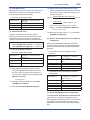
3.3.5 Total Flow Setup
(1) Mode setting
Set the parameters to start, stop, and reset the total
flow.
To start the total flow measurement by normal
mode, call up the Total Flow Mode display and set
the mode.
• Procedure to call up the display
DD (HART 5/7) [Root Menu] → Detailed setup →
DTM (HART 7) Signal condition → Total Flow → Total
Flow Mode →
DTM (HART 5) Configuration → Total Flow → Total
Flow Mode →
Reset
Reset the total flow value
Start
Start the total flow measurement.
Total value is limited at 9.99E29.
Stop
Stop the total flow measurement
Start Cyclic
Start the total flow measurement.
When the total flow value reaches
999999, the count restarts at 0.
(2) User unit configuration
You can set your own unit for total flow.
Select the Base Unit as an base unit, then set the
Cvt Val for the conversion coefficient with the user
unit.
• Procedure to call up the display for DD
(HART 5/HART 7) and DTM (HART 7)
DD (HART 5/7) [Root Menu] → Detailed setup →
DTM (HART 7) Signal condition → Total Flow →
Config User Unit →
→ Set Base
Select the Base Unit from the list
Unit
→ Modify Unit Set the special total flow unit
→ Cvt Val
Enter the conversion value
• Procedure to call up the display for DTM
(HART 5)
DTM (HART 5)
→ Conf User Unit Set
Base Unit
→ Conf User Unit
Modify Unit
→ Conf User Unit Cvt
Val
Configuration → Total Flow →
Select the Base Unit from
the list
Set the special total flow unit
Enter the conversion value
Base Unit
g
kg
t
lb
STon
LTon
oz
gal
L
Impgal
m3
bbl
yd3
ft3
in3
Nm3
NL
SCF
Available characters and symbols for Engr Unit are
the same as for Modify Engr Unit shown above.
IM 01C25R02-01E
<3. Parameter Setting>
Typical Unit Conversion Factor
3.3.6 Sensor Trim
Use “kg” in case of mass flow
Use “m3” in case of volume flow
Use “Nm3” in case of normal or standard volume flow
Set Base Unit
kg
m3
Nm3
User Unit
g
kg
t
lb
STon
LTon
oz
gal
L
Impgal
m3
bbl
bushel
yd3
ft3
in3
bbl
hl
Nm3
NL
SCF
3-20
Convert val
1.0000E+03
1.0000E+00
1.0000E-03
2.2046E+00
1.1023E-03
9.8421E-04
3.5274E+01
2.6417E+02
1.0000E+03
2.1997E+02
1.0000E+00
6.2898E+00
2.8378E+01
1.3080E+00
3.5315E+01
6.1024E+04
6.2898E+00
1.0000E+01
1.0000E+00
1.0000E+03
3.5315E+01
<Example>
Set the special total flow unit as g (=0.001kg) based
kg.
(1kg=1.0000E+03g)
1) Select “kg” for Set base unit (or Conf User Unit Set
Base Unit).
2) Set “g” for Modify Unit (or Conf User Unit Modify
Unit).
3) Enter 1.0000E+03 for Cvt Val (or Conf User Unit Cvt
Val).
NOTE
Up to eight alphanumeric characters, spaces or
slash(/) can be input for Modify Unit (or Conf
User Unit Modify Unit).
EJX multivariable transmitter is factory
characterized. Factory characterization is the
process of comparing a known pressure input with
the output of each transmitter sensor module over
the entire pressure and temperature operating
range. During the characterization process, this
comparison information is stored in the transmitter
EEPROM. In operation, the transmitter uses this
factory-stored curve to produce a process variable
output (PV), in engineering units, dependent on the
pressure input.
The sensor trim procedure allows you to adjust
for local conditions, changing how the transmitter
calculates process variables. There are two ways
to trim the sensor: a zero trim and a full sensor trim.
A zero trim is a one-point adjustment typically used
to compensate for mounting position effects or
zero shifts caused by static pressure. A full sensor
trim is a two-point process, in which two accurate
end-point pressures are applied (equal to or greater
than the range values), and all output is linearized
between them.
Full Sensor Trim—Auto Trim and Manual Trim Full sensor trim is carried out by performing Auto,
Lower Pt followed by Auto, Upper Pt.
Also, you can manually perform the trimming
procedure with Manual, Lower Pt and Manual,
Upper Pt.
The full sensor trim is a two-point adjustment,
and the lower point adjustment should always be
performed before the upper point adjustment in
order to maintain the pitch between the zero and
100% points within the calibration range.
In the manual method, the reference pressure
should also be applied to the transmitter at both
the lower and upper points. Without the reference
pressure, Manual, Lower Pt and Manual, Upper
Pt may not represent the correct value for each
adjustment point.
IM 01C25R02-01E
(1) Auto Sensor Trim
Applying reference pressure of 0% and 100% of the
measurement range to the transmitter, adjust the
lower and upper points automatically.
• Procedure to call up the display
DD (HART 5/7)
DTM (HART 7)
DTM (HART 5)
→ Auto, Lower Pt
→ Auto, Upper Pt
[Root Menu] → Diag/Service →
Calibration → Pres sensor trim →
Pres trim →
Calibration → Pressure trim →
Auto trim for 0% point
Auto trim for 100% point
<5> Suppose that a standard pressure of 3000
mmH2O is applied and the value of the Pres for
trim is 3015.0. Firstly, obtain the slope error for
the span as follows;
Slope Error =
=
(2) Manual Sensor Trim
Using the example below, follow the steps to
perform the full sensor trim by manually. The Pres
LTD (Manual, Lower Pt) and Pres UTD (Manual,
Upper Pt) represent the previously adjusted values.
Example: For the range of 1000 to 3000 mmH2O
Pres LTD (Manual, Lower Pt) = −4.0 mmH2O
Pres UTD (Manual, Upper Pt) = −3.0 mmH2O
<1> Call up the Manual, Lower Pt.
• Procedure to call up the display
DD (HART 5/7)
DTM (HART 7)
DTM (HART 5)
→ Manual, Lower
Pt
→ Manual, Upper
Pt
[Root Menu] → Diag/Service →
Calibration → Pres sensor trim →
Pres trim →
Calibration → Pressure trim →
Manual trim for 0% point
Manual trim for 100% point
<2> Suppose that a standard pressure of 1000
mmH2O is applied and the value of the “Pres
for trim” is 994.0. Correct for this output error
of 6 mmH2O by adding 6 mmH2O to Pres LTD
(Manual, Lower Pt).
3-21
<3. Parameter Setting>
−4.0+6.0=+2.0
<3> Enter the correction value of “2” to the Pres
LTD (Manual, Lower Pt).
<4> Call up the Pres UTD (Manual, Upper Pt).
Applied Pressure Value−Value of Pres for Trim
Applied Pressure Value
× (URV−LRV)
3000−3015
× (3000−1000) = −10
3000
Then correct for this slope error of −10 by
adding −10 to Pres UTD (Manual, Upper Pt).
−3.0+(−10.0)=−13.0
<6> Enter the correction value of “−13” to the Pres
UTD (Manual, Upper Pt).
(3) Sensor Trim for Static Pressure or External
Temperature
For the EJX multivariable transmitter, full sensor
trim of the static pressure or external temperature is
performed in the same way as with the differential
pressure.
• Procedure to call up the display for static
pressure
DD (HART 5/7)
DTM (HART 7)
DTM (HART 5)
→ Auto, Lower Pt
→ Auto, Upper Pt
→ Manual, Lower Pt
→ Manual, Upper Pt
[Root Menu] → Diag/Service
→ Calibration → SP sensor
trim → SP trim →
Calibration → Static Pressure
trim →
Auto trim for 0% point
Auto trim for 100% point
Manual trim for 0% point
Manual trim for 100% point
• Procedure to call up the display for external
temperature
DD (HART 5/7)
DTM (HART 7)
DTM (HART 5)
→ Auto, Lower Pt
→ Auto, Upper Pt
→ Manual, Lower Pt
→ Manual, Upper Pt
[Root Menu] → Diag/Service
→ Calibration → ET Sensor
trim → ET trim →
Calibration → External Temp
trim →
Auto trim for 0% point
Auto trim for 100% point
Manual trim for 0% point
Manual trim for 100% point
(4) Reset Trim Adjistment to Factory Setting
The Clear P trim, Clear SP trim and Clear ET trim
commands can reset the trim adjustment to the
initial calibrated values that were set. The amount of
the adjustment performed with the external zeroadjustment screw is returned to the initial setting as
well.
IM 01C25R02-01E
• Procedure to call up the display for differential
pressure
DD (HART 5/7)
DTM (HART 7)
DTM (HART 5)
[Root Menu] → Diag/Service →
Calibration → Pres Sensor trim →
Clear P trim → Execute
Calibration → Clear Pressure Sensor
trim → Execute
• Procedure to call up the display for static
pressure
DD (HART 5/7)
DTM (HART 7)
DTM (HART 5)
[Root Menu] → Diag/Service →
Calibration → SP Sensor trim →
Clear SP trim → Execute
Calibration → Clear Static Pressure
Sensor trim → Execute
• Procedure to call up the display for external
temperature
DD (HART 5/7)
DTM (HART 7)
DTM (HART 5)
3-22
<3. Parameter Setting>
[Root Menu] → Diag/Service →
Calibration → ET Sensor trim →
Clear ET trim → Execute
Calibration → Clear External Temp
Sensor trim → Execute
<Example>
Adjustment using a volt meter. (4mA → 1V, 20mA
→ 5V)
1) Select “Change”.
2) Enter the value read on the voltmeter when the output signal is 4mA.
In this case, enter the value of the voltage across a
250Ω resistor (1V).
3) Enter the value read on the meter when the output
signal is 20mA (5V).
4) Select “Proceed”.
5) Connect the voltmeter.
6) Output the 0% output signal and read the output
value.
7) Enter the reading of the voltmeter to the configuration
tool. (The output of the transmitter changes).
8) Confirm the voltmeter reading is 1.000.
9) If the reading on the voltmeter is 1.000, select “Yes”.
3.3.7 Trim Analog Output
Fine current output adjustment is carried out with
D/A trim or Scaled D/A trim.
10) Output the 100% output signal and read the output
(1) D/A Trim
11) Enter the reading of the voltmeter.
D/A trim is to be carried out if the calibration digital
ammeter does not exactly read 4.000 mA and
20.000 mA with an output signal of 0% and 100%.
• Procedure to call up the D/A trim display
DD (HART 5/7)
DTM (HART 7)
DTM (HART 5)
[Root Menu] → Diag/Service →
Calibration
→ Analog output trim → D/A trim
Calibration → D/A trim
(2) Scaled D/A Trim
Scaled D/A trim is to be carried out if the output is
adjusted using a voltmeter or a meter whose scale
is 0 to 100%.
• Procedure to call up the Scaled D/A trim
display
DD (HART 5/7)
DTM (HART 7)
DTM (HART 5)
[Root Menu] → Diag/Service →
Calibration
→ Analog output trim →Scaled D/A
trim
Calibration → Scaled D/A trim
If the reading is not 1.000, select “No” and repeat
steps 6 and 7 until the voltmeter reads 1.000V.
value.
12) Confirm the voltmeter reading is 5.000.
13) If the reading of the voltmeter is 5.000, select “Yes”.
If the reading on the voltmeter is not 5.000, select
“No” and repeat steps 10 and 11 until the voltmeter
reads 5.000V.
3.3.8 External Switch Mode
Follow the procedure below to enable or inhibit zero
point adjustment by means of the zero-adjustment
screw on the transmitter.
This is set to “Disabled” when the instrument is
shipped.
To change the mode, follow the procedure below.
• Procedure to call up the display
DD (HART 5/7) [Root Menu] → Detailed setup →
DTM (HART 7) Device information → Field device info
→ Ext SW
DTM (HART 5) Configuration → Device information1
→ Ext SW
Enabled
Enable the external zero point
adjustment
Disabled
Disable the external zero point
adjustment
IM 01C25R02-01E
3-23
<3. Parameter Setting>
3.3.9 CPU Failure Burnout Direction and
Hardware Write Protect
There are two slide switches on the CPU assembly
board. One sets the burnout direction at CPU
failure, and the other sets a write protection function
which disables parameter changes through
the use of a handheld terminal or some other
communication method.
CPU assembly
Burnout direction switch
BO H
L
WR E
D
Slide switch
Write protection switch
Burnout direction switch (BO)
Burnout Direction
Switch Position
H
Burnout Direction
L
H
HIGH
L
Write Protection
When write protection is set to ”Yes,” the transmitter
does not accept parameter changes. When the
same eight alphanumeric string entered in the New
password field is also entered in the Enable wrt
10min field and transferred to the transmitter, it
will be possible to change transmitter parameters
during a 10 minute period.
To change the transmitter from the write protection
”Yes” status back to write protection ”No” status,
use Enable wrt 10min to first release the write
protection function and then enter eight spaces in
the New password field.
[Root Menu] → Detailed setup →
Device information → Field device
info → Wrt protect menu →
→ Write Protect
Display current protect mode
(Yes: protected, No: not protected)
→ Enable wrt 10 Release the protect function for 10
min
min.
→ New password Set the new password or change
the password
DD (HART 5/7)
DTM (HART 7)
H
L
H
L
E
D
E
D
NO
(Write enabled)
EJX multivariable transmitter configured data is
saved by using a write protection function. The
write protection status is set to “Yes” when 8
alphanumeric characters are entered in the New
password field and transferred to the transmitter.
• Procedure to call up the display using DD
(HART 5/HART 7) and DTM (HART 7)
LOW
Hardware write protection switch (WR)
Write Protection
Switch Position
3.3.10 Software Write Protection
YES
(Write disabled)
F0305.ai
The parameter of AO alm typ parameter displays
the status of 4-20 mA DC output if a CPU failure
occurs. In case of a failure, communication is
disabled.
Standard specifications or with option code /C3
The burnout direction switch is set to “HIGH”. If a
failure occurs, the transmitter outputs a 110% or
higher signal.
With option code /C1 or /C2
The burnout direction switch is set to “LOW”.
If a failure occurs, a –2.5% or lower output is
generated.
To confirm the burnout direction at the CPU failure,
follow the procedure below.
• Procedure to call up the display
DD (HART 5/7) [Root Menu] → Detailed setup →
DTM (HART 7) Output condition → Analog output →
AO alm typ
DTM (HART 5) Configuration → Analog output → AO
alm typ
High
Burnout direction is set to High
Low
Burnout direction is set to Low
• Procedure to call up the display using DTM
(HART 5)
DTM (HART 5) Write Protect →
→ Write Protect Display current protect mode
(Yes: protected, No: not protected)
→ Enter new
Enter the password here to enable
password
the protect function.
Enter eight spaces to disable the
protect function.
→ Enable write Enter the password here to release
the protect function for 10 min.
3.3.11 Alarm
The function is used to display the alarm codes
when the input differential pressure exceeds the
specified value within the calibration range. The
same is available for the input static pressure,
external temperature, and flow rate. Refer to table
4.5 Alarm Message Summary for the specific alarm
code to be generated.
IM 01C25R02-01E
<3. Parameter Setting>
3-24
(1) Alarm Setting
• Procedure to call up the display
Select the process variable at Process Alert which
the alarm is set, then set the alert mode for that
value.
DD (HART 5/7) [Root Menu] → Detailed setup →
DTM (HART 7) Output condition → Process Alerts →
DO config → DO Signal type
DTM (HART 5) Configuration → Process Alerts → DO
Signal type
Status Output On When Al. Output is “ON” when
Detect
alert is detected
Off When Al. Output is “OFF” when
Detect
alert is detected
Pulse Output
Scaled Pulse Scaled pulse output
Frequency
Frequency output
• Procedure to call up the display
DD (HART 5/7)
DTM (HART 7)
DTM (HART 5)
Selection of
the process
variable for
alarm
Selection of
alert mode
[Root Menu] → Detailed setup →
Output condition → Process Alerts →
Configuration → Process Alerts →
→ Pres Alert Mode: Differential
pressure
→ SP Alert Mode: Static pressure
→ ET Alert Mode: External
temperature
→ Flow Alert Mode: Flow rate
Off: Disable the alert function
Hi Al Detect: High side alert detection
Lo Al Detect: Low side alert detection
Hi/Lo Al Detect: High and Low side
alert detection
(2) Threshold Level Setting
Set the threshold of high and low alert value for
alarm generation.
• Procedure to call up the display
DD (HART 5/7)
DTM (HART 7)
DTM (HART 5)
Parameter
→ Pres Hi Alert
Val
→ Pres Lo Alert
Val
→ SP Hi Alert
Val
→ SP Lo Alert
Val
→ ET Hi Alert
Val
→ ET Lo Alert
Val
→ Flow Hi Alert
Val
→ Flow Lo Alert
Val
[Root Menu] → Detailed setup →
Output condition → Process Alerts →
Configuration → Process Alerts →
Detail
Set the threshold value of upper side
for differential pressure
Set the threshold value of lower side
for differential pressure
Set the threshold value of upper side
for static pressure
Set the threshold value of lower side
for static pressure
Set the threshold value of upper side
for external temperature
Set the threshold value of lower side
for external temperature
Set the threshold value of upper side
for flow rate
Set the threshold value of lower side
for flow rate
3.3.12 Status Output and Pulse Output
<Example>
Set the status output to output an off signal when
the input pressure exceeds 75 kPa with the alert
mode of Hi. Al Detect.
1) Select “Off When Al. Detect”
2) Select “Pres Alert Mode: Differential pressure” (Refer
to subsection 3.3.11(1) Alarm Setting)
3) Select “Hi Al Detect: High side alert detection” (Refer
to subsection 3.3.11(1) Alarm Setting)
4) Enter “75kPa” to Pres Hi Alert Val (Refer to subsection 3.3.11(2) Threshold Level Setting)
CAUTION
Whenever turning on the transmitter or detecting
the short interruption, check if contact output
correctly reflects the alarm status and test
the ON/OFF action of contact output by the
parameter DO test to confirm that the contact
output operates correctly.
(2) Setting of status output
This feature is used for a transistor output (open
collector) of an on/off signal according to the
status of high and low alarm limits, which are
user-configurable values as shown in subsection
3.3.11 Alarm. The status output can be assigned
as any combination of the high or low limits of
the input pressure, input static pressure, external
temperature, or flow.
EJX multivariable transmitter has a contact output.
Select the type of output, status output or pulse
output, and set the unit, value etc.
(1) Selecting of output signal
Status output or pulse output can be selected for
the contact output.
IM 01C25R02-01E
• Procedure to call up the display
[Root Menu] → Detailed setup →
Output condition → Process Alerts
→ DO config → DO Select
DTM (HART 5) Configuration → Process Alerts →
DO Select
Display Item
Contents (Select a output variable
from the list below)
Off
–
Pres
Differential pressure
SP
Static pressure
Temp
External temperature
Pres/SP
Differential pressure and static
pressure
Pres/Temp
Differential pressure and external
temperature
SP/Temp
Static pressure and external
temperature
Pres/SP/Temp
Differential pressure, static pressure
and external temperature
Flow
Flow rate
Pres/Flow
Differential pressure and flow rate
SP/Flow
Static pressure and flow rate
Temp/Flow
External temperature and flow rate
Pres/SP/Flow
Differential pressure, static pressure
and flow rate
Pres/Temp/Flow Differential pressure, external
temperature and flow rate
SP/Temp/Flow
Static pressure, external
temperature and flow rate
Pres/SP/Temp/ Differential pressure, static pressure,
Flow
external temperature and flow rate
Diag Alarm
Alarm for advanced diagnostics
(Refer to subsection 4.2.2.5)
All
Alarm for differential pressure, static
pressure, external temperature, flow
rate, and advanced diagnostics
DD (HART 5/7)
DTM (HART 7)
NOTE
No status output signal has been defined for a
CPU failure or hardware error. Use a 4-20 mA
signal to indicate a transmitter’s failure.
3-25
<3. Parameter Setting>
Example: Status output operation of ON
WHEN AL. DETECT
Status output for higher alert value
Output
(%)
5%* of hysteresis
Setting
value
On
Status output
On
Time (t)
Off
Status output for lower alert value
Output
(%)
Setting
value
5%* of hysteresis
On
Status output
On
Time (t)
Off
*: 5% of setting span for differential pressure / pressure
F0306.ai
Figure 3.2 Status Output
(3) Setting of pulse output
When the pulse output is used, either scaled pulse
output or frequency output is selected in subsection
3.3.12 (1).
Then configure the parameter shown below.
a. Scaled pulse
A single pulse is output for a specified flow
amount.
b. Frequency output
The flow rate is determined from the number of
output pulses per second.
IM 01C25R02-01E
<3. Parameter Setting>
3.3.13 Test Output, Simulation, and Squawk
Example of Pulse Output
The number of pulses (PPS)
NOTE
T = 1sec
(*1) Example of scaled pulse
Pulse Rate =10kg
(*2) Example of freqency output
Configuration: Freq at 100% =10000Hz
Flow Rate: URL =100% 10000(PPS)
F0307.ai
Scaled pulse
• Procedure to call up the display
DD (HART 5/7)
DTM (HART 7)
DTM (HART 5)
→ Total Flow Unit
→ Pulse rate
[Root Menu] → Detailed setup →
Signal condition → Total Flow →
Configuration → Total Flow →
Select the unit of total flow
Set the volumetric flow rate or
mass flow rate per one pulse.
<Example>
Scaled pulse 10 kg Set
1) Enter “kg” to Total Flow Unit
2) Enter “10” to Pulse rate
Frequency output
• Procedure to call up the display
DD (HART 5/7)
DTM (HART 7)
DTM (HART 5)
→ Freq at 100%
[Root Menu] → Detailed setup →
Signal condition → Total Flow →
Configuration → Total Flow →
Set the number of output pulse per
second at 100% flow rate.
Max. frequency: 10kHz
Duty cycle: Approx 50%
<Example>
Freq at 100% is 10000 Hz Set
1) Enter “10000” to Freq at 100%
3-26
Fixed current output, DO Test, Flow Simulation
Mode, and Device Variable Simulation Function
continue for a given holding time, then is
released automatically. Even if the HART
configuration tool power supply is turned off or
the communication cable is disconnected, the
test output will continue for that time.
The holding time can be selected from 10 min*,
30 min, 60 min, 3 hour, 6 hour or 12 hour.
*: Default value.
• Procedure to call up the display
DD (HART 5/7)
DTM (HART 7)
DTM (HART 5)
[Root Menu] → Diag/Service
→ Test Auto Release Time
Diag and Service → Service
→ Test Auto Release Time
(1) Fixed current output
This feature can be used to output a fixed current
for loop checks. The available range for test output
depend on the settings for the AO lower limit and
AO upper limit parameters, whose limit is from
3.8mA (-1.25%) to 21.6mA (110%).
Refer to the subsection 3.3.1 about the setting of
AO lower limit and AO upper limit.
While this function works, “TEST” is displayed on
the integral indicator.
In the case of using DD (HART 5/HART 7)
and DTM (HART 7)
Call up the test output parameter (Loop test) and
select the output signal.
• Procedure to call up the display
DD (HART 5/7)
DTM (HART 7)
Display Item
4mA
20mA
Other
End
[Root Menu] → Diag/Service →
Test → Loop test →
Contents
Output a 4mA DC signal
Output a 20mA DC signal
Set a desired output signal value
Exit
In the case of using DTM (HART 5)
Call up the test output parameter (Loop test) and
select either manual test or auto test, and set the
current value.
IM 01C25R02-01E
<3. Parameter Setting>
3-27
• Procedure to call up the display
• Procedure to call up the display
DTM (HART 5)
[Root Menu] → Detailed setup →
Simulation/Flow Simulation* →
Configuration → Simulation →
Off:
–
ON: DP Differential pressure only
ON: SP Static pressure only
(Select the
ON: DP Differential pressure and
combination
SP static pressure
of pseudo
ON:
ET
External temperature only
variables)
ON: DP Differential pressure and
ET external temperature
ON: SP Static pressure and external
ET temperature
ON: DP Differential pressure, static
SP pressure and external
ET temperature
Check
Differential pressure, static
Flow
pressure, and external
Calc
temperature without
damping
Select the unit for the differential
→ Sim Pres
Unit
pressure
→ Sim Pres
Set the differential pressure value for
simulation
It is similar about SP and ET.
Display Item
Manual Test
Auto Test
Diag and Service → Service →
Loop test →
Contents
Set the current value or % value at
Test output value, then click the
Start button.
Set the interval and rate of change
of current output at Auto Test
Setting, then click the Start button.
(2) DO Test
This function performs the contact and pulse output
test.
• Procedure to call up the display
DD (HART 5/7) [Root Menu] → Detailed setup →
DTM (HART 7) Output condition → Process Alerts →
DO config → DO Test →
DTM (HART 5) Diag and Service → Service → DO
test →
Display Item
Contents
Status High
Contact output: OFF
Status Low
Contact output: ON
Frequency
Frequency range 0 to 10,000Hz
Exit
Output test is canceled
DD (HART 5/7)
DTM (HART 7)
DTM (HART 5)
→ Simulation
Mode
*: “Simulation” is for HART 5, “Flow Simulation” is for HART 7
(3) Flow Simulation Mode
The flow value can be calculated by using pseudo
values instead of using actual measurements of
differential pressure, static pressure, and external
temperature.
This is called “flow simulation mode.”
The output current value becomes the simulation
value and the LCD continuously displays the
simulation value and alarm (AL.90 SIM) in
alternating sequence.
F0308.ai
Select the desired simulation mode from the list
below, and set the unit and value.
IM 01C25R02-01E
• Procedure of device variable simulation
NOTE
The output process value while simulation
can be monitored by LCD and through
communication as follows.
Process value
DP
SP
ET
Flow Rate
Total Flow
Output value
Simulation value according to
simulation mode
Simulation value according to
simulation mode
Simulation value according to
simulation mode
Flow calculation value using the
DP, SP, ET simulation value
Flow Rate accumulation value
Following function is reflected to flow calculation
while simulation.
Simulation
value
DP/SP/ET
DP
3-28
<3. Parameter Setting>
Step 1 Call up the
parameter
2
Selection of
Device Variable
Select one parameter from
the list below
Off
Flow
Pres
SP
ET
Total Flow
PV
SV
TV
QV
% Range
Loop Current
3
Setting of Value
Input the simulate value
4
Setting of Data
quality
Select one parameter from
the list below
Bad
Poor accuracy
Manual / Fixed
Good
5
Setting of Limit
status
Select one parameter from
the list below
Not limited
Low limited
High limited
Constant
Function
Measuring Range (LRV/URV)
Alarm
Status Output
Damping Time*
Low Cut Mode
*: When “Check Flow Calc” is selected, damping is ignored.
If one of the following alarm occurs while
simulation, all of the output data are held to the
value before alarm occurs.
AL.01 (CAP. ERR)
AL.02 (AMP. ERR)
AL.03 (ET. ERR)
(4) Device Variable Simulation Function
(Effective only when setting to HART 7)
Using the simulation function, the output signal can
be confirmed by setting any value and status to the
selected device variable.
Call up the parameter and follow the message
shown.
After completing the step 5, the simulation starts.
Integral indicator shows output and alarm (AL.91)
alternately.
[Root Menu] → Diag/
Service → Test → Simulate
NOTE
• The flow rate is calculated from differential
pressure, static pressure, and external
temperature, and the total flow is
accumulated from the flow rate. Therefore,
the simulation results for the flow rate and
total flow depend on the simulation settings
of differential pressure, static pressure, and
external temperature. The total flow depends
on the flow rate as well.
• The total flow simulation is only applied for
LCD display and communication output and
does not affect the total flow value.
• All the simulations for differential pressure,
static pressure, external temperature,
flow rate are reflected to the output.
Accordingly, the loop current, LCD display,
and communication output are directly
corresponded to the simulate value.
The alarm output is also available according
to the simulate value.
• Damping is applicable for differential
pressure, static pressure, and external
temperature simulation.
IM 01C25R02-01E
(5) Squawk (Effective only when setting to
HART 7)
This feature can be used to identify the
communicating transmitter by remotely causing
LCD to display the particular pattern as shown in
the Figure 3.3.
“SQUAWK” continues for approximately 15
seconds, then is released automatically.
Enter the larger number to “Change number of
squawks to make” in order to prolong the duration
of squawk indication.
• Procedure to call up the Squawk display
[Root Menu] → Diag/Service → Test → Squawk
P
SP
T
3.3.14 Basic Flow Calculation (Basic mode)
In the case of Basic mode, flow operation and
density compensation are performed conventionally
with the flow factors manually input.
The flow rate is calculated using the constant flow
factor.
Density is compensated as follows according to the
selection of gas or liquid.
Gas: Compensation as ideal gas by
temperature and pressure.
Liquid: Compensation by temperature.
There are an automatic compensation mode and
basic mode in the flow calculation, and either is
selected in the Flow Calc Mode parameter.
• Procedure to call up the display
F
DD (HART 5/7)
DTM (HART 7)
DTM (HART 5)
F0309.ai
Figure 3.3
3-29
<3. Parameter Setting>
LCD display for Squawk
Display Item
Basic Mode
Auto Comp.
Mode
[Root Menu] → Detailed setup →
Basic Flow Calc → Flow Calc Mode
→
Configuration → Basic Flow Calc →
Flow Calc Mode →
Contents
Basic calculation mode
Automatic compensation mode
(Use FSA120 for this mode)
Select “Basic Mode” here, and set the parameters
according to the procedure of Table 3.2.
FSA120 (FieldMate FlowNavigator) can configure
both automatic compensation mode and basic
mode. For detail, refer to the User’s Manual of
FSA120 FieldMate FlowNavigator (IM 01C25R5101E).
IM 01C25R02-01E
3-30
<3. Parameter Setting>
Table 3.2
Basic Flow Calc Set-up Steps
Step
Parameter
Contents
1
Flow Calc Mode Select Basic Mode
2
Fluid Type
Select liquid or gas
3
Flow Calc Fixed Input Kfactor
4
Ref SP
5
6
Ref Temp
Temp K1
Remarks
Kfactor calculated by Table 3.3 Flow Equation and Kfactor
Calculation
This factor is used for gas.
When fluid type is liquid, set 0 to Ref SP(Spb).
Input reference static
pressure
Input reference temperature
Input the density rate of
This factor is used for mass flow and normal standard volume flow
change per temperature
of liquid. When fluid type is gas or volume flow of liquid, set 0 to
1degC.
TempK1. Refer to Table 3.4 Symbol
Equation for Basic flow calculation
The flow equation shown in Table 3.3 is applied to the transmitter by combination of fluid type and flow unit
category.
Table 3.3
Flow Equation and Kfactor Calculation
Fluid Type Flow unit category
liquid
Gas
*1
*2
Kfactor
Flow Equation
*2
Mass Flow
Kfactor = /4 × Nc × C /
× 2 × ρb
Normal-Standard
Volume Flow
Kfactor = /4 × Nc × C / 1- β4 × ε × d2
× 2 × ρb / ρ norm
Volume Flow
Kfactor = /4 × Nc × C /
× 2 / ρb
Mass Flow
Kfactor = /4 × Nc × C / 1- β4 × ε × d2
× 2 × ρb × 1/K
Normal-Standard
Volume Flow
Kfactor = /4 × Nc × C / 1- β4 × ε × d2
× 2 × ρb × 1/K / ρ norm
Volume Flow
Kfactor = /4 × Nc × C / 1- β4 × ε × d2
× 2 / (ρb × 1/K)
2
Qm, Qv or Qv_norm
= Kfactor ×
∆ρ × (1+ Temp K1 × (T-Tb))
1- β4 × ε × d2
mark indicate user input.
Kfactor must be calculated according to the specified flow unit.
Table 3.4
*1
1- β × ε × d
4
*1
Qm or Qv_norm
= Kfactor ×
Qv = Kfactor ×
∆ρ × Tb/T × SP/SPb
*1
∆ρ × T/Tb × SPb/SP
T0310.ai
Symbol
No
1
2
3
4
5
6
7
8
9
10
11
12
13
14
15
16
17
Symbol
Qm
Qv
Qv_norm
Nc
Kfactor
C
ε
β
d
∆p
ρb
ρ norm
Tb
T
SPb
SP
Temp K1
18
K
Description
Mass Flow
Volume Flow
Normal-Standard Volume Flow
Unit convert factor
Basic flow Calcuration factor
Discharge Coefficient
Expansion Factor
Diameter Ratio
Diameter of orifice
Differential Pressure (Transmitter setting unit)
Base Density on Tb, SPb condition
Density on Normal, Standard condition
Reference temperature (unit: K)
Temperature (unit: K)
Reference static pressure (unit: kPa abs)
Static Pressure (unit: kPa abs)
The density rate of change per temperature 1degC of a density base value (value which set 100%
to 1). For volume flow: set 0.
Compressibility factor
Note 1. The flow unit is not automatically converted. Refer to IM 01C25R01-01E for Nc calculation.
Note 2. Kfactor, SPb, and Tb are calculated using the equipment setting unit (differential pressure, static pressure, and temperature).
Note 3. Total flow is calculated using the transmitter setting unit.
IM 01C25R02-01E
Flow unit category
Table 3.5
Table 3.7
Mass Flow Unit
Unit
grams per second
grams per minute
grams per hour
Kilograms per second
kilograms per minute
kilograms per hour
kilograms per day
metric tons per minute
metric tons per hour
metric tons per day
pounds per second
pounds per minute
pounds per hour
pounds per day
short tons per minute
short tons per hour
short tons per day
long tons per hour
long tons per day
Table 3.6
3-31
<3. Parameter Setting>
LCD
g/s
g/m
g/h
kg/s
kg/m
kg/h
kg/d
t/m
t/h
t/d
lb/s
lb/m
lb/h
lb/d
STon/m
STon/h
STon/d
LTon/h
LTon/d
Communication
←
g/min
←
←
kg/min
←
←
t/min
←
←
←
lb/min
←
←
STon/min
←
←
←
←
Normal/Standard Volume Flow Unit
Unit
normal cubic meter
per hour
normal liter per hour
standard cubic feet
per minute
standard liter per hour
standard liter per
minute
standard liter per
second
normal cubic meter
per day
standard cubic feet
per day
standard cubic feet
per hour
standard cubic feet
per second
standard cubic meter
per day
standard cubic meter
per hour
thousand standard
cubic feet per day
million standard cubic
feet per day
LCD
Communication
Nm3/h
←
NL/h
←
SCFM
←
SL/h
←
SL/m
SL/min
SL/s
←
Nm3/d
←
SCFD
←
SCFH
←
SCFS
←
Sm3/d
←
Sm3/h
←
MSCFD
←
MMSCFD
←
Volume Flow Unit
Unit
cubic feet per minute
gallons per minute
liters per minute
imperial gallons per
minute
cubic meter per hour
gallons per second
million gallons per day
liters per second
million liters per day
cubic feet per second
cubic feet per day
cubic meters per
second
cubic meters per day
imperial gallons per
hour
imperial gallons per
day
cubic feet per hour
cubic meters per
minute
barrels per second
barrels per minute
barrels per hour
barrels per day
gallons per hour
imperial gallons per
second
liters per hour
gallons per day
LCD
CFM
GPM
L/m
Communication
←
←
L/min
IGal/m
lmpgal/min
m3/h
gal/s
Mgal/d
L/s
ML/d
CFS
ft3/d
←
←
←
←
←
←
←
m3/s
←
m3/d
←
IGal/h
lmpgal/h
IGal/d
lmpgal/d
CFH
←
m3/m
m3/min
bbl/s
bbl/m
bbl/h
bbl/d
gal/h
←
bbl/min
←
←
←
IGal/s
lmpgal/s
L/h
gal/d
←
←
IM 01C25R02-01E
3.3.15 Burst Mode
3.3.15.1In the case of using HART 5
When the Burst mode is enabled, the transmitter
continuously sends the stored data. The data is
sent approximately three times per second as a
digital signal when the transmitter is set in burst
mode. When data is being sent in burst mode,
other operations can be performed with the HART
configuration tool.
(1) Selection of the transmission data.
Call up the Burst option parameter and select the
data which is transferred.
• Procedure to call up the display
DD (HART 5)
DTM (HART 5)
Display Item
PV
%range/current
Process vars/
crnt
Xmtr Variables
3-32
<3. Parameter Setting>
[Root Menu] → Detailed setup →
Output condition
→ HART output → Burst option →
Configuration → HART → Burst
option →
Contents
Process variable assigned to PV
(Either of differential pressure, static
pressure, external temperature, and
flow rate)
Output in % and mA
Output in mA and process variables
assigned to PV, SV, TV, and 4V.
(Output in mA and four variables
from differential pressure, static
pressure, external temperature, flow
rate, and total flow.)
Selectable up to four variables from
differential pressure, static pressure,
external temperature, flow rate, and
total flow.
According to the procedure indicated
in Burst Xmtr Vars, set the selected
variables to four Slot.
(For the Slot that is not used, set the
same value as others.)
• Procedure to call up the display
DD (HART 5)
DTM (HART 5)
Display Item
Off
On
[Root Menu] → Detailed setup →
Output condition → HART output →
Burst mode
Configuration → HART → Burst
mode
Contents
Stop the burst mode
Start the burst mode
3.3.15.2In the case of using HART 7
When the Burst mode is enabled, the transmitter
continuously sends up to three data listed in Table
3.8.
Refer to the subsection 3.3.15.2.1 Burst Message
for details.
When the Burst mode is set to “Wired HART
Enabled”, transmitter continuously sends alarm
signal also.
Refer to subsection 3.3.15.2.2 Event Notification for
detail.
When changing the setting of Burst mode, set “Off”
to the Burst mode.
Default setting is “Off”.
3.3.15.2.1 Burst Message and Burst Mode
(1) Burst message
EJX multivariable transmitter can transmit three
burst messages at the maximum.
The parameters for Burst Message are as follows.
• Burst Command
• Update Period and Max Update Period
• Burst Msg Trigger Mode
(2) Shift to the Burst mode.
To enable the Burst mode, select “On” at the Burst
mode parameter.
To release the Burst mode, call up the Burst
mode display and set it to “Off”.
This parameter is set to “Off” when the instrument is
shipped.
IM 01C25R02-01E
Table 3.8
<3. Parameter Setting>
3-33
Burst parameters
Burst Msg Trigger
Mode
PV
Cmd1:PV
Continuous
(Either of differential
Window
pressure, static pressure,
Rising
external temperature, flow
Falling
rate)
On-change
% range/current
Cmd2:% range/current
Continuous
(Percent of range, Loop
Window
current)
Rising
Falling
On-change
Process vars/current
Cmd3:Dyn vars/current
Continuous
(Loop current, PV, SV, TV,
Window
QV)
Rising
Falling
On-change
Process vars/% range/
Cmd9:Device vars w/Status Continuous
current with status*1
Window
(Select up to eight variables
Rising
from differential pressure,
Falling
static pressure, external
On-change
temperature, flow rate, total
flow, percent of range, loop
current, PV, SV, TV and
QV)*2
Process vars/% range/
Cmd33:Device Variables
Continuous
current
Window
(Select up to four variables
Rising
from differential pressure,
Falling
static pressure, external
On-change
temperature, flow rate, total
flow, percent of range, loop
current, PV, SV, TV, and
QV)*2
Self diagnosis information Cmd48:Read
Continuous
Additional Device Status
On-change
Command parameter
Burst Command
Burst Trigger
Source
--PV
Burst Trigger Units
--Depend on the
assigned variable to
PV
--% range
--%
--PV
--Depend on the
assigned variable to
PV
----Top of Burst
Depends on mapping
Device Variables
Top of Burst
Depend on the
Device Variables assigned variable to
Burst Device Variables
--All status
-----
*1 : Output the data with time and status.
*2 : Select at Burst Device Variables
IM 01C25R02-01E
3-34
<3. Parameter Setting>
(2) Burst mode setting procedure
• Procedure to call up the display
DD (HART 7)
DTM (HART 7)
[Root Menu] → Detailed setup →
Output condition →HART output →
Burst Condition → Burst Message
1,2 or 3 → Burst Command
a. Burst Command
Burst Command
Send to EJX
Cmd9, Cmd33
Burst
Command?
Cmd1, Cmd2,
Cmd3, Cmd48
Burst Variable Code
b. Burst Variable Code
Send to EJX
Update Period
Max Update Period
c. Update period and
Max Update Period
by “Set Burst Period”
Send to EJX
d. Burst Msg Trigger Mode
by “Set Burst Trigger”
Burst Msg Trigger Mode
Window
Rising
Falling
On-change
Burst Msg
Trigger Mode?
Continuous
Burst Trigger Level
Send to EJX
e. Burst Mode
Burst mode
Send to EJX
F0311.ai
IM 01C25R02-01E
<3. Parameter Setting>
a. Burst Command
• Procedure to call up the display
Select the transmission data at Burst Command
parameter.
DD (HART 7)
DTM (HART 7)
Burst Command
Cmd1: PV
Cmd2: % range/current
Command parameter
Variable assigned to PV
% range/current (Percent of
range, Loop current)
Cmd3: Dyn vars/current Process vars/current
(Loop current, PV, SV, TV,
QV)
Cmd9: Device vars
Process vars/% range/current
w/Status
Mapping by user
Cmd33: Device
Process vars/% range/current
Variables
Mapping by user
Cmd48: Read
Self diagnosis information
Additional Device
Status
b. Burst Variable Code
This parameter need to be set when Burst
Command is Cmd9:Device vars w/Status (up to
eight items) and Cmd33: Device Variables (up to
four items).
• Procedure to call up the display
DD (HART 7)
DTM (HART 7)
Display Item
Flow
Pres
SP
ET
Total Flow
PV
SV
TV
QV
% rnge
Loop current
Not Used
[Root Menu] → Detailed setup →
Output condition →HART output →
Burst condition → Burst Message
1,2 or 3 → Burst Device Variables →
Burst Variable Code →
Contents
Select the flow rate
Select the differential pressure
Select the static pressure
Select the external temperature
Select the total flow
Select the PV value
Select the SV value
Select the TV value
Select the QV value
Select the % output
Select the output current
–
c. Update period and Max Update Period
Set to Update Period and Max Update Period.
When the period that is earlier than the operation
period of each process value was set, it is set
automatically to become bigger than an operation
period of EJX multivariable transmitter.
For Update Period, set the value that is smaller
than Max Update Period.
→ Update Period
/ Max Update
Period
3-35
[Root Menu] → Detailed setup
→Output condition →HART
output → Burst condition → Burst
Message 1,2 or 3 → Set Burst
Period
0.5 s
1s
2s
4s
8s
16 s
32 s
1 min
5 min
10 min
15 min
30 min
45 min
60 min
d. Burst Msg Trigger Mode
Set the Burst Msg Trigger Mode from the
parameters shown below.
When Burst Msg Trigger Mode is Window, Rising
or Falling, set the Burst Trigger Level.
• Procedure to call up the display
DD (HART 7)
[Root Menu] → Detailed setup →
DTM (HART 7) Output condition →HART output →
Burst condition → Burst Message 1,2
or 3 → Set Burst Trigger →
Display Item
Contents
Continuous
Burst Message is transmitted
continuously.
Window
In “Window” mode, the Trigger Value
must be a positive number and is the
symmetric window around the last
communicated value.
Rising
In “Rising” mode, the Burst Message
must be published when the source
value exceeds the threshold
established by the trigger value.
Falling
In “Falling” mode, the Burst Message
must be published when the source
value fall below the threshold
established by the trigger value.
On-change
In “On-change” mode, the Burst
Message must be published when the
source value on change established
by the trigger value.
IM 01C25R02-01E
<3. Parameter Setting>
e. Burst Mode
When the Burst mode is set to “Wired HART
Enabled”, the transmitter starts to send the data.
• Procedure to call up the display
DD (HART 7)
DTM (HART 7)
[Root Menu] → Detailed setup →
Output condition
→HART output → Burst condition
→ Burst Message 1,2 or 3 →
Burst mode → Wired HART
Enabled
3.3.15.2.2 Event Notification
When a setting change and a change of the Selfdiagnostics occur, device detect it as an event and
can transmit an alarm signal continuously.
Up to four events that occurred can be stored.
When using this function, set to Burst mode as
“Wired HART Enabled”.
(1) Set Event Notification
• Procedure to call up the display
DD (HART 7)
DTM (HART 7)
→ Event Mask
→ Event
Notification
Retry Time
→ Max Update
Time
→ Event Debounce
Interval
→ Event
Notification
Control
[Root Menu] → Detailed setup
→Output condition →HART
output → Burst condition →
Event Notification →
Set the status to detect
Set the retry time when the event
occur.
Set the retry time when the event
does not occur.
The setting of the minimum event
duration
Stop the event monitor: Off
Shift to the monitor state: Enable
event notification on tokenpassing data link layer
Event Notification
Retry Time
/Max Update Time
--0.5 s
1s
2s
4s
8s
16 s
32 s
1 min
5 min
10 min
15 min
30 min
45 min
60 min
Event Debounce Interval
Off
0.5 s
1s
2s
4s
8s
16 s
32 s
1 min
5 min
10 min
15 min
30 min
45 min
60 min
c) Event Notification Control
Select “Enable event notification on token-passing
data link layer” in the Event Notification Control
parameter to shift to the monitor state:
(2) Acknowledge Event Notification
The transmission of the event message stops when
event is approved.
• Procedure to call up the display
DD (HART 7)
DTM (HART 7)
→ Acknowledge
Event Notification
[Root Menu] → Detailed
setup →Output condition →
HART output → Burst condition
→ Event Notification →
Knowledge →
Acquisition of the event number
and approval.
a) Event Mask
a) Get Event Number
Set the status to detect in the Event Mask
parameter.
Confirm the latest event number.
Device Status Mask
Status group 1 Mask to 11 Mask
Ext dev status Mask
Device Diagnostic Status 0 Mask
Device Diagnostic Status 1 Mask
AO saturated Mask
AO fixed Mask
3-36
Execute Acknowledge Event Notification
method.
1)Enter Event Number is set to “0”.
2)OK.
3)Set “Trans 0: Read Event Notificaiton” to
Select Transaction.
4)OK.
5)Confirm Event Number.
b) Event Notification Retry Time/ Max Update
Time/ Event Debounce Interval
Set to Event Notification Retry Time, Max Update
Time and Event Debounce Interval.
For Event Notification Retry Time, set the value
that is smaller than Max Update Time.
IM 01C25R02-01E
b) Acknowledge Event Notification
Execute Acknowledge Event Notification
method.
1)Set to Enter Event Number is in confirmed
Event Number a)5.
2)OK.
3)Set “Trans 1: Send Acknowledge” to Select
Transaction.
4)OK.
5)Confirm Event Status is 0x00.
(3) Event Notification Record
• Procedure to call up the display
DD (HART 7)
DTM (HART 7)
→ Acknowledge
Event Notification
[Root Menu] → Detailed setup →
Output condition →HART output
→ Burst condition → Event
Notification → Knowledge →
Acquisition of the event number
and approval.
a) Get Event Number
Confirm the latest event number.
Execute Acknowledge Event Notification
method.
1)Enter Event Number is set to “0”.
2)OK.
3)Set “Trans 0: Read Event Notificaiton” to
Select Transaction.
4)OK.
5)Confirm Event Number.
b) Confirmation record of Event Notification
Confirm four events checked in a).
Execute Acknowledge Event Notification
method.
1)Enter the event number to Enter Event
Number which is confirmed in a)5.
2)OK.
3)Set “Trans 0: Read Event Notificaiton” to
Select Transaction.
4)OK.
5)Knowledge menu displays events record.
Ex.) When the confirmed event number is 123.
123
122
121
120
Event Number
3-37
<3. Parameter Setting>
Explanation
The latest event
An event before the once.
An event before the twice.
An event before three times.
3.3.16 Multidrop Mode
3.3.16.1In the case of using HART 5
“Multidropping” transmitters refer to the connection
of several transmitters to a single communication
transmission line. Up to 15 transmitters can be
connected when set in the multidrop mode. To
activate multidrop communication, the transmitter
address must be changed to a number from 1 to
15. This change deactivates the 4 to 20 mA analog
output, sending it to 4 mA. The alarm current is also
disabled.
Setting of Multidrop Mode
(1) Polling address
• Procedure to call up the display
DD (HART 5)
DTM (HART 5)
→ Poll addr
[Root Menu] → Detailed setup →
Output condition → HART output →
Configuration → HART →
Enter the number from 1 to 15
(2) Enabling the Multidrop Mode
About the procedure to call up the Polling
display, please refer to the User’s Manual of each
configuration tool.
NOTE
When the same polling address is set for
two or more transmitters in multidrop mode,
communication with these transmitters is
disabled.
(3) Communication when set in multidrop
mode.
• The HART configuration tool searches for a
transmitter that is set in multidrop mode when
it is turned on. When the HART configuration
tool is connected to the transmitter, the polling
address and the tag will be displayed.
• Select the desired transmitter. After that, normal
communication to the selected transmitter is
possible. However, the communication speed
will be slow.
To release multidrop mode, call up the Poll addr
display and set the address to “0”.
IM 01C25R02-01E
3.3.16.2In the case of using HART 7
“Multidropping” transmitters refer to the connection
of several transmitters to a single communication
transmission line. Up to 63 transmitters can be
connected when set in the multidrop mode. To
activate multidrop communication, the transmitter
address must be changed to a number from 1 to
63. This change deactivates the 4 to 20 mA analog
output, sending it to 4 mA. The alarm current is also
disabled.
Setting of Multidrop Mode
(1) Polling address
• Procedure to call up the display
[Root Menu] → Detailed setup
→Output condition →HART
output →
Enter the number from 1 to 63
DD (HART 7)
DTM (HART 7)
→ Poll addr
(2) Enabling the Multidrop Mode
About the procedure to call up the Polling
display, please refer to the User’s Manual of each
configuration tool.
When Loop current mode is set to “Enabled”, an
analog signal output is available for one device in a
loop.
• Procedure to call up the display
DD (HART 7)
DTM (HART 7)
Enabled
Disabled
3-38
<3. Parameter Setting>
[Root Menu] → Detailed setup →
Output condition →Analog output →
Loop current mode →
Loop current mode is enabled.
Loop current mode is disabled.
NOTE
When the same polling address is set for
two or more transmitters in multidrop mode,
communication with these transmitters is
disabled.
(3) Communication when set in multidrop
mode.
• The HART configuration tool searches for a
transmitter that is set in multidrop mode when
it is turned on. When the HART configuration
tool is connected to the transmitter, the polling
address and the tag will be displayed.
• Select the desired transmitter. After that, normal
communication to the selected transmitter is
possible. However, the communication speed
will be slow.
To release multidrop mode, call up the Poll addr
display and set the address to “0”.
3.3.17 Switching HART Protocol Revision
When the output signal code is “-J”, HART protocol
revision of EJX multivariable transmitter can be
selectable from 5 or 7.
The HART protocol revision is set and shipped as
specified in the order.
To change the HART protocol revision after
shipment, follow the procedure shown below.
IMPORTANT
When changing the protocol revision, confirm the
items below.
• Protocol revision supported by HART
configuration tool must be the same or
higher than new protocol revision of the EJX
multivariable transmitter. (Refer to Table 2.1)
• Confirm that the DD or DTM which is suitable
to new protocol revision of EJX multivariable
transmitter is installed in the configuration
tool. (Refer to Section 2.3 or 2.4)
1) Call up the parameter for protocol revision
change
• Procedure to call up the Chg universal rev
display.
DD (HART 5/7)
DTM (HART 7)
DTM (HART 5)
[Root Menu] → Detailed setup →
Device information → Field device
info → Revision #’s → Chg universal
rev
Configuration → HART → Chg
universal rev
2) Activate the “Chg universal rev” method
IMPORTANT
The message is displayed to separate the
transmitter from the automatic control loop.
Confirm that the transmitter is separated.
3) Input the new revision number
An input column for new protocol revision number is
displayed.
Input the new HART protocol revision number of “5”
for HART 5 or “7” for HART 7.
IM 01C25R02-01E
<3. Parameter Setting>
3-39
4) Applying the new protocol revision
a. Close the configuration tool
After completion of Chg universal rev
method, close the HART configuration tool.
NOTE
When using a FieldMate, close the main display
of FieldMate.
b.Restart the transmitter
Turn off the power to the transmitter, and turn
it on.
IMPORTANT
New protocol revision is applied only after having
performed restart of the transmitter.
NOTE
A new HART revision number is displayed on
the integral indicator for three (3) seconds after
restart the transmitter. (Refer to section 2.1)
5) Confirming the new protocol revision
a.Restart the HART configuration tool
NOTE
When execute the other parameter confirmation
or setting change, execute after restart the
configuration tool.
b.Confirm the new HART protocol revision
number
Call up the Universal rev parameter, and confirm
that the new HART revision number is displayed.
• Procedure to call up the Universal rev.
parameter.
DD (HART 5/7)
DTM (HART 7)
DTM (HART 5)
5
7
[Root Menu] → Detailed setup
→ Device information → Field
device info → Revision #’s →
Universal rev →
Configuration → HART →
Universal rev. →
HART protocol revision: 5
HART protocol revision: 7
IM 01C25R02-01E
4.
<4. Diagnostics>
4-1
Diagnostics
4.1 Self-Diagnostics
(2) Using DTM(HART 5)
4.1.1 Identify Problems by Using the
HART Configuration Tool
The HART configuration tool can be used to run
self-diagnostics on a transmitter and check for
incorrect data settings.
(1) Using DD(HART 5/HART 7) and
DTM(HART 7)
The Device Status commands are used for selfdiagnostics. When Device Status is run, the
integral indicator shows an error code and alarm
message if the transmitter detects any illegal
parameter settings or functional faults. See Table
4.5 Alarm Message Summary for probable cause
and countermeasures.
• Procedure to call up the Device Status display
The Self test and Status commands are available
for self-diagnostics. When Self test is run, the
integral indicator shows an error code and alarm
message if the transmitter detects any illegal
parameter settings or functional faults. See Table
4.5 Alarm Message Summary for probable cause
and countermeasures.
• Procedure to call up the Self test display
[Root Menu] → Diag/Service → Test → Self test
If no error is detected, “Self test OK” is displayed on
the configuration tool.
If the specific diagnostic item is known for the
check, you can directly call up the item by using the
Status command.
The status is categorized from 1 to 10 for HART 5,
and from 1 to 11 for HART 7.
See Table 4.5 to determine the status group.
Show an example below to confirm the status of
Status group 1.
Device Status
If no error is detected, “Status: Normal” is displayed
on the configuration tool.
If the specific diagnostic item is known for the
check, you can directly call up the item by using the
Diagnostic List in the Device Status display.
The Diagnostic List is categorized to Device Status,
Hardware Failure, Transducer Status, Diag Status,
and Configuration.
See Table 4.5 Alarm Message Summary.
If no error is detected, color symbol which shows
Normal State is displayed on top of the error
message.
If color symbol which shows Error State is
displayed, there is an error and a countermeasure
for that error is necessary.
• Procedure to call up the Status display
[Root Menu] → Diag/Service → Status → Status group 1
If no error is detected, “Off” is displayed on the
configuration tool.
If there is an error, “On” is displayed on the
configuration tool, and a countermeasure for that
error is necessary.
Example of display:
Illegal P LRV
Illegal P URV
Illegal P SPAN
P SPAN trim err
P ZERO trim err
On
Off
Off
Off
Off
The HART configuration tool diagnoses at each
communication.
When an improper operation is performed, the error
message is displayed.
See Table 4.6 HART Configuration Tool Error
Message.
The HART configuration tool diagnoses at each
communication.
When an improper operation is performed, the error
message is displayed.
See Table 4.6 HART Configuration Tool Error
Message.
IM 01C25R02-01E
4.1.2 Checking with Integral Indicator
NOTE
If an error is detected by running self-diagnostics,
an error number is displayed on the integral
indicator. If there is more than one error, the error
number changes at three-second intervals.
See table 4.3.1 regarding the alarm codes.
F0401.ai
Figure 4.1
4-2
<4. Diagnostics>
Integral Indicator
4.1.3 Status information available for
HART 7
Status added to HART 7 is explained below.
(1) Device Status
Device Status indicates the current operating
status of the device. (Refer to Table 4.7)
Table 4.10 indicates the relationship between
alarm and Device Status.
• Procedure to call up the display using DD
(HART 7) and DTM (HART 7)
DD (HART 7)
[Root Menu] → Diag/Service →
DTM (HART 7) Status → Device Status
(2) Extended Device Status
Ext dev status contains commonly used
device information. (Refer to Table 4.8)
Table 4.10 indicates the relationship between
alarm and Extended Device Status.
• Procedure to call up the display using DD
(HART 7) and DTM (HART 7)
DD (HART 7)
[Root Menu] → Diag/Service →
DTM (HART 7) Status → Ext dev status
(3) Data quality and Limit status
EJX multivariable transmitter can handle
Dynamic Variables (PV, SV, TV, QV) and Device
Variables (DP(Pres), SP, ET, Flow, Total Flow,
% range, Loop current). Each variable contains
data quality and limit status for providing useful
status about the data value. The data quality
is normally “Good”. However, in the case of a
sensor failure or out of measurement range,
it turns to “Bad” or “Poor Accuracy”. The limit
status indicates whether the data value is
limited (i.e., not responding to the process).
When the limit status is “Constant”, the value
will not be changed. For detail, refer to Table 4.9
and 4.10.
• Procedure to call up the display using DD
(HART 7) and DTM (HART 7)
[Dynamic Variables]
DD (HART 7)
[Root Menu] → Process variables
DTM (HART 7)
→ Output vars → PV →
→ PV Data
Good, Poor Accuracy, Manual/
Quality
Fixed, or Bad is displayed.
→ PV Limit
Constant, Low Limit, High Limit, or
Status
Not Limited is displayed.
It is the same about the SV, TV, and QV.
[Device Variables]
DD (HART 7)
[Root Menu] → Process variables
DTM (HART 7)
→ Device variables and Status →
→ Flow Data
Good, Poor Accuracy, Manual/
Quality
Fixed, or Bad is displayed.
→ Flow Limit
Constant, Low Limit, High Limit, or
Status
Not Limited is displayed.
It is the same about the Pres, SP, ET, Total Flow, %
Range, and Loop Current. .
(4) Time Stamp
Time Stamp displays the date and the time
information which EJX multivariable transmitter
maintains from the time of the power on.
It is used as the additional information of the
process value and the event.
• Procedure to call up the display using DD
(HART 7) and DTM (HART 7)
DD (HART 7)
DTM (HART 7)
→ Current Date
→ Current Time
[Root Menu] → Diag/Service →
Status → Time Stamp
It shows the number of operating
days.
It shows the running time.
IM 01C25R02-01E
4.2 Advanced Diagnostics
NOTE
Time Stamp is reset when powering on.
(5) Configuration Change Counter
The Configuration Change Counter is
incremented once for every user action
that changes the device’s configuration or
calibration. This value is never reset or written
and maintained even if power is removed from
the device.
• Procedure to call up the display using DD
(HART 7) and DTM (HART 7)
DD (HART 7)
DTM (HART 7)
→ Cfg chng
count
4-3
<4. Diagnostics>
[Root Menu] → Diag/Service →
Status →
The configuration change times
are counted. The counted value
cannot be reset.
(6) Reset Configuration Changed Flag
Configuration Changed Flag can be reset by
this method.
NOTE
Refer to Configuration Changed (0x40) in the
Table 4.7.
• Procedure to call up the display using DD
(HART 7) and DTM (HART 7)
DD (HART 7)
[Root Menu] → Diag/Service →
DTM (HART 7) Status → Reset Cfg Chng flag
4.2.1 Multi-sensing Process Monitoring
Multi-sensing process monitoring function (option
code: /DG6) provides the advanced diagnostics
to detect the abnormal conditions in process
environment such as an impulse line etc. by using
the EJX multisensing technology and its unique
algorithm. There are following two functions.
Impulse Line Blockage Detection (ILBD)
The fluctuation change of differential pressure and
static pressure is monitored by a silicone resonant
sensor and detects a potential blockage condition.
The differential pressure transmitter gives also a
result of which pressure-side was plugged.
Heat Trace Monitoring
The two temperature sensors built in the EJX
multivariable transmitter calculate the flange
temperature, the change of which enables to
detect the heat trace breakage or the abnormal
temperature due to the failure.
4.2.2 Impulse Line Blockage Detection
(ILBD)
ILBD is carried out by using statistical analysis
based on the measured values of process
fluctuations that exist in a fluid. An alarm on the EJX
multivariable transmitter LCD display or an analog
alert is generated if blockage reaches a certain
level. EJX multivariable transmitter provides the
following results as blockage detection.
(1) A Blocking and B Blocking
These are blockage detections based on
the fluctuation value change of differential
pressure/pressure. With a differential pressure
transmitter, each result indicates that both or
single side is plugged.
(2) L Side Blocking
It is a low-pressure side blockage detection
based on the change of BlkF or low-pressureside fluctuation value.
(3) H Side Blocking
It is a high-pressure side blockage detection
based on the change of BlkF or high-pressureside fluctuation value.
*: BlkF indicates blockage degree characterized
by a comparison of the high- and low-pressureside fluctuation values. For the details, refer to
Figure 4.2.2.
IM 01C25R02-01E
<4. Diagnostics>
4-4
IMPORTANT
• The pressure fluctuation amplitude in fluids
must be sufficiently large for blockages to be
detected.
• If the pressure fluctuation amplitude is too
low for a reference value to be obtained,
blockages detection operation cannot be
performed with an alarm that the reference
value is invalid.
• The pressure fluctuation amplitude may
decrease due to other causes unrelated with
a blockage according to process condition. In
above case, a false alarm of an impulse line
blockage may be generated. Before taking
action in response to a blockage alarm,
consider the plant operating conditions.
Notes for Pressure or Level
Measurement
With pressure or level measurement, the pressure
fluctuation amplitude may reduce especially for the
following cases.
Pressure Measurement
• Operational pressure is near outside of
diagnostic range.
• Even though pressure is constant, the flow
decreases than that under normal condition.
• A source of pressure fluctuation (pump,
compressor, blower, etc.) is shut down. As
a result, the pressure fluctuation amplitude
decreases.
Level Measurement
• A transmitter is used to measure tank level and
the flow of fluid into or out of the tank comes to
a stop.
• The agitator in the tank is shut down.
• A source of pressure variation (a compressor,
etc.) that controls the internal pressure of a
sealed (closed) tank is shut down.
Before taking action in response to a blockage
alarm, consider the plant operating conditions.
IM 01C25R02-01E
4-5
<4. Diagnostics>
Functional block diagram
The figure below shows the functional block diagram of ILBD.
Pres, SP, ET, Flow,
Total Flow,
Engr Disp, PV %,
Cap temp,
Amp temp
EJX multivariable transmitter
Sensor
Sensor
signals
Process Value
calculation
Blockage alarm
Diag Output
Option
DO Config
Blockage alarm
Blockage degree
Add result of
blockage detection to status
Result of blockage detection
Execution of
ILBD
*1: Only for DD(HART 5/HART 7) and DTM(HART 7)
In the case of DTM(HART 5), color of icon in the
Diag Error display changes according to the status.
Alarm
Masking
Result of blockage detection
Blockage alarm
4-20mA DC
(Analog Output)
-------(6)
Contact Output
(Digital Output)
-------(7)
Ratio fDP
Ratio fSPl
Ratio fSPh
BlkF
fDP
fSPl
fSPh
Diag Applicable*1
-------(1)
Diag Error
-------(4)
Response Code
(Device Status)
Status group 9,10
-------(2)
-------(3)
Display on LCD
-------(5)
F0402.ai
Figure 4.2
Functional Block Diagram of ILBD
The following outputs are given for the ILBD results.
Table 4.1
#
List of Outputs for ILBD
OUTPUT
Parameter name
Ratio fDP
Remarks
Parameters based on the fluctuation value and blockage degree.
: Non-Compensation ]
[ Diag DPComp:
fDP
Ratio fDP =
Ref fDP
[ Diag DPComp:
: Compensation ]
Ratio fSPl
(1)
Ratio fSPh
BlkF
fDP
fSPI
fSPh
Diag Applicable*1
(2)
Response Code
Device Status
(3) Status group 9,10
Ratio fSPl =
Ratio fDP =
fDP
Ref fDP
×
Ref DPAvg
DPAvg
fSPl
Ref fSPl
fSPh
Ref fSPh
Blockage degree characterized in comparison of high-pressure side and low-pressure
side pressure fluctuation value.
Average value of the sum of squares of differential pressure fluctuations.
Average value of the sum of squares of low-pressure side static pressure fluctuation.
Average value of the sum of squares of high-pressure side static pressure fluctuation.
After the reference value is obtained, the applicable blockage defection and the status of
abnormal fluctuation are displayed on this parameter.
Ratio fSPh =
When an impulse line blockage is detected, “More Status Avairable” is generated in
Response Code Device Status.
When an impulse line blockage is detected, the result of the blockage detection
(alarm status) is indicated.
(4) Diag Error
When an impulse line blockage is detected, the results of the blockage detection
(alarm status) is indicated.
(5) Display on LCD
(6) Analog Output
(7) Digital Output
When impulse line blockage is detected, an alarm status is displayed on LCD.
When impulse line blockage is detected, an alarm status is output on 4 to 20mA.
When impulse line blockage is detected, an alarm status is output on Status output.
F0403.ai
IM 01C25R02-01E
4.2.2.1 Blockage Detection
Limit parameter
When the parameter based on pressure fluctuation
exceeds the preset value, EJX diagnoses an
impulse line as blockage and gives an alarm. The
threshold values are set to Limit parameter shown
in below table.
• Procedure to call up the display
DD (HART 5/7) [Root Menu] → Diag/Service → Diag
DTM (HART 7) Parameters → ILBD Parameters →
Configuration → Diag Lim →
DTM (HART 5) Diag and Service → Advanced Diag
Configurations → Impulse Line
Blockage Detection → Threshold
→ Sensitivity →
Table 4.2
Limit Parameter
#
Parameter
Threshold value
[1] Lim fDPmax
Threshold to detect “A
Blocking” by using Ratio fDP
[2] Lim fDPmin
Threshold to detect “B
Blocking” by using Ratio fDP
[3] Lim fSPlmax
Threshold to detect “Large
Fluct L” by using Ratio fSPl
[4] Lim fSPlmin
Threshold to detect “L Side
Blocking” by using Ratio fSPl
[5] Lim fSPhmax
Threshold to detect “Large
Fluct H” by using Ratio fSPh
[6] Lim fSPhmin
Threshold to detect “H Side
Blocking” by using Ratio fSPh
[7] Lim BlkFmax
Threshold to detect “H Side
Blocking” by using BlkF
[8] Lim BlkFmin
Threshold to detect “L Side
Blocking” by using BlkF
[9] Lim DPAvgmax Threshold to detect “ILDB over
range” by using DPAvg and to
detect “Invalid Ref xx” by using
Ref DPAvg
[10] Lim DPAvgmin
Threshold to detect “ILDB over
range” by using DPAvg and to
detect “Invalid Ref xx” by using
Ref DPAvg
Table 4.3 shows the default values at the factory
setting.
NOTE
• When ILBD is performed for the first time,
use the default value. If the pressure
fluctuation amplitude is low or a false alarm
is often generated after ILBD is performed,
change the values of Limit parameters
according to the procedure described in
subsection 4.2.2.10. Tuning
4-6
<4. Diagnostics>
Table 4.3
Default Values of Limit Parameter
Multivariable Transmitter
#
Parameter
[1]
Lim fDPmax
3
[2]
Lim fDPmin
0.3
[3]
Lim fSPlmax
5
[4]
Lim fSPlmin
0.5
[5]
Lim fSPhmax
5
[6]
Lim fSPhmin
0.5
[7]
Lim BlkFmax
0.6
[8]
Lim BlkFmin
-0.6
[9]
Lim DPAvgmax
Note 1
1
[10]
Lim DPAvgmin
0.05
Note 1
EJX910A, EJX930A
Note 1: It indicates the threshold value for “ILBD over range”
(refer to subsection 4.2.2.5).
A/B Blocking Detection
“A Blocking” and “B Blocking” indicates the result
estimated from blockage degree based on the
difference of the high- and low-pressure-side
fluctuation values. Ratio fDP, SQRT (fDP / Ref
fDP) is used to detect A/B blocking. Ref fDP is the
average value of the sum of squares of differential
pressure fluctuations under normal condition.
As the value of Ratio fDP exceeds the value of
Lim fDPmax, EJX gives basically an alarm of “A
Blocking”. On the other hand, if this value is below
the value of Lim fDPmin, EJX gives an alarm of “B
Blocking.
As a high- or low-pressure-side blockage
progresses, fDP increases. Therefore, “A Blocking”
with a differential pressure transmitter indicates
that a single-side impulse line is plugged for a
differential pressure transmitter. As the both-side
blockages progress simultaneously, fDP decreases.
Therefore, “B Blocking” with a differential pressure
transmitter indicates that both-side impulse lines
are plugged.
NOTE
A single-side impulse line blockage may
generate “B blocking” under the condition where
the fluctuation amplitude is much different
between high- and low-pressure sides.
IM 01C25R02-01E
H/L Blocking Detection
EJX differential pressure transmitter enables
to detect both-, a high-, or low-pressure-side
blockage. The blockage degree characterized
by a comparison of high-pressure side and lowpressure-side fluctuation values, BlkF, is used to
detect it. The value changes within a range of –1
to +1. As BlkF approaches +1, the high-pressureside blockage progresses. On the other hand, if it
approaches –1, the low-pressure-side blockage
progresses.
1
1
Blockage Progress
-1
BlkF
BlkF
Threshold
0
4-7
<4. Diagnostics>
0
-1
Blockage detection for
high-pressure side
Blockage Progress
Threshold
On the other hand, if this value exceeds the value of
Lim fSPhmax, EJX gives an alarm of “Large Fluct
H”.
Large Fluctuation Detection
When a pump or compressor starts, the large
fluctuation is generated as process condition
changes rapidly. This phenomenon affects process
fluctuation measurement; so correct blockage
detection is not performed.
If “Large Fluct L” or “Large Fluct H” is detected,
consider whether a blockage result is correct.
The threshold values to detect large fluctuation are
set to Lim fSPlmax and Lim fSPhmax.
Since these values are enough to detect large
fluctuation, it is not almost necessary to change
them.
Blockage detection for
low-pressure side
F0404.ai
Figure 4.3
Relation between Blockage Progress
and BlkF
The each threshold value to detect the high- or lowpressure-side blockage is set to Lim BlkFmax or
Lim BlkFmin.
L Side Blocking Detection
BlkF is preferentially used to "L Side Blocking"
detection. If BlkF cannot be used, Ratio fSPl,
SQRT (fSPl / Ref fSPl) is used to "L Side Blocking"
detection. Ref fSPl is the average value of the sum
of squares of low-pressure-side static pressure
fluctuations under normal condition.
As the value of Ratio fSPl is below the value of Lim
fSPlmin, EJX gives an alarm of "L Side Blocking".
On the other hand, if this value exceeds the value of
Lim fSPlmax, EJX gives an alarm of “Large Fluct
L”.
H Side Blocking Detection
BlkF is preferentially used to "H Side Blocking"
detection. If BlkF cannot be used, Ratio fSPh,
SQRT (fSPh / Ref fSPh) is used to "H Side
Blocking" detection. Ref fSPh is the average value
of the sum of squares of high-pressure-side static
pressure fluctuations under normal condition.
As the value of Ratio fSPh is below the value
of Lim fSPhmin, EJX gives an alarm of "H Side
Blocking".
IM 01C25R02-01E
4-8
<4. Diagnostics>
4.2.2.2 Combination of Reference Result
and Blockage Detection
Diag Applicable
An EJX multivariable transmitter can detect four
modes of impulse line blockage: both-sides, highpressure side, low-pressure side, and/or single-side
and abnormal fluctuation when all the reference
values are properly measured. However, the
detectable alarm mode combination is limited when
some of the reference values are invalid. Available
Blockage Detection are shown in the below figure.
NOTE
• Ref fDP must be larger than the specified
level shown in Table 4.4 (refer to subsection
4.2.2.6). No blockage can be detected when
Ref fDP is not large enough.
• The plausibility of blockage detection needs
to be confirmed by blockage simulation test.
The simulation test can be performed by
the appropriate manifold operation (refer to
subsection 4.2.2.8).
[Differential pressure measurement]
Fluctuation Parameters
Ref fDP:
OK
Ref fSPI:
OK
Ref fSPh:
OK
Ref BlkF:
OK
Ref fDP:
OK
Ref fSPI:
OK
Ref fSPh:
OK
Ref BlkF:
NG
Ref fDP:
OK
Ref fSPI:
NG
Ref fSPh:
OK
Ref BlkF:
NG
Ref fDP:
OK
Ref fSPI:
NG
Ref fSPh:
NG
Ref BlkF:
NG
Simulation Test
• Test for low-pressure side
• Test for high-pressure side
• Test for both-pressure sides
• Test for low-pressure side
• Test for high-pressure side
• Test for both-pressure sides
• Test for high-pressure side
Available Blockage Detection
• B Blocking detection
(by using Ratio fDP)
• L Side Blocking detection
(by using Ratio fSPI)
• H Side Blocking detection
(by using Ratio fSPh)
• H/L Side Blocking detection
(by using BlkF)
• A/B Blocking detection
(by using Ratio fDP)
• L Side Blocking detection
(by using Ratio fSPl)
• H Side Blocking detection
(by using Ratio fSPh)
• A Blocking detection
(by using Ratio fDP)
• H Side Blocking detection
(by using Ratio fSPh)
• B Blocking detection
(by using Ratio fDP)
• Test for both-pressure sides
[Gauge/absolute pressure and level measurement]
Fluctuation Parameters
Ref fDP:
OK
Simulation Test
• Test for high-pressure side
Available Blockage Detection
• B Blocking detection
(by using Ratio fDP)
F0405.ai
IM 01C25R02-01E
4.2.2.3 Operation Parameters
Diag Mode
Diag Mode gives the directive for the ILBD
operation. There are following three modes.
• Procedure to call up the display
DD (HART 5/7) [Root Menu] → Diag/Service → Diag
DTM (HART 7) Parameters → ILBD Parameters →
Configuration → Set Diag Mode →
DTM (HART 5) Diag and Service → Advanced Diag
Configurations → Impulse Line
Blockage Detection → Diag Mode →
Diag Mode
Mode
Stop
Function
The blockage detection operation is
stopped.
Calculation The blockage detection operation is
performed.
Alarms are generated along with the
result.
Reference Reference values for the blockage
detection are obtained and updated to the
latest. After sampling reference values,
this mode changes to "Calculation".
When the blockage detection operation is
performed, set “Calculation” to Diag Mode. “Stop”
must be set when you change a threshold value or
set an alarm. “Reference” is set in order to obtain
the reference fluctuation values under the normal
configuration.
NOTE
When setting ILBD parameters in the transmitter
via “Online Parameter” of the DTM (HART 5)
menu, Diag Mode automatically changes to 0
(Stop). After the setting, Diag Mode automatically
returns to the original value.
<4. Diagnostics>
4-9
Diag Period
The values such as Ratio fDP and BlkF are
averaged based on several hundreds of pressure
fluctuation values in constant time. Diag Period
defines the sampling time is. The default value at
the shipment is set to 180 sec.
• Procedure to call up the display
DD (HART 5/7) [Root Menu] → Diag/Service → Diag
DTM (HART 7) Parameters → ILBD Parameters →
Configuration → Diag Period →
DTM (HART 5) Diag and Service → Advanced Diag
Configurations → Impulse Line
Blockage Detection → Diag Period →
For the information on how to change the sampling
period, refer to subsection 4.2.2.10.
Diag Supp Count
When the value as Ratio fDP or BlkF exceeds
the threshold value for several times in a row,
it is estimated that the impulse line is plugged.
Diag Supp Count defines the number of times to
estimate blockage detection.
• Procedure to call up the display
DD (HART 5/7) [Root Menu] → Diag/Service → Diag
DTM (HART 7) Parameters → ILBD Parameters →
Configuration → Diag Supp Count →
DTM (HART 5) Diag and Service → Advanced Diag
Configurations → Impulse Line
Blockage Detection → Threshold →
Diag Suppress Count →
If Diag Supp Count is set to three times, an
alarm is not generated at part ‘A’ in Figure 4.4.
Because the first and second values only exceeded
consecutively the threshold.
When the value exceeds consecutively the
threshold value three times, an alarm is generated
(see part ‘B’ in Figure 4.4).
NOTE
When setting ILBD parameters in the transmitter
via “Download to device” of the DTM (HART 5)
menu, Diag Mode automatically changes to 0
(Stop).
IM 01C25R02-01E
<4. Diagnostics>
4-10
Diag Supp Count (Number of times: 3)
An alarm is generated.
A
B
B
B
Upper Threshold
(Ex.Lim fDPmax)
Diag Period
Time
Diag Period
A
Lower Threshold
(Ex.Lim fDPmin)
A
A
B
An alarm is generated.
Diag Supp Count (Number of times: 3)
Time
F0406.ai
Figure 4.4
Relationship of Diag Supp Count and
Alarm
The number of detection to give an alarm is set for
each blockage detection function. The default value
at the shipment is set to three times.
If fluctuating around the threshold value, an alarm
may be often generated. In this case, change the
threshold value (Limit parameter) or the sampling
time (Diag Period) to enhance the accuracy of the
blockage detection. Refer to subsection 4.2.2.10.
IM 01C25R02-01E
4-11
<4. Diagnostics>
4.2.2.4 Operating Procedure
If an alarm is often generated or the process
condition changed in the ILBD operation, do
tuning to change the alarm setting, or to reset the
reference values.
The basic flow of the ILBD operation is as follows.
1)Initial setting
2)Condition check
3)Start up
4)Perform the ILBD algorithm.
Fill out the information to the checklist, at the
process shown in below figure.
(Refer to the Appendix 1. ILBD Check List)
Items on
Check sheet
1-1) Alert Setting
• Enable an alert to be generated by
Diag Out Option parameter.
1, 2
Refer to subsection 4.2.2.5
1) Initial Setting
1-2) Alarm Masking
• Select the alarm status to display on
LCD or to give an alert by Diag
Option parameter.
7
Refer to subsection 4.2.2.5
2-1) Check Stability of pressure
• Check the stability of Pres value.
3
2) Condition
Check
4
Refer to subsection 4.2.2.6
2-2) Check Fluctuation Values
• Check whether the fluctuation values
are available for ILBD.
Refer to subsection 4.2.2.6
3-1) Obtain Reference Values
• Obtain a reference fluctuation value of
differential pressure/pressure and
static pressure under normal condition.
5, 6
Refer to subsection 4.2.2.7
3) Start up
10
3-2)
Check Detection
Capability
• Simulate the blockage detection
operation with a three-valve
manifold or stop valve.
NG
Tuning
• Change the threshold value by
Limit parameter.
• Change the sampling time by
Diag Period parameter.
Refer to subsection 4.2.2.8
Refer to
subsection 4.2.2.10
OK
4) Perform ILBD algorithm
Spurious alarm detection.
Refer to
subsection 4.2.2.9
Reset Reference Values
• Reset a reference fluctuation
value of differential
Process condition is
pressure/pressure according to
changed by a
process condition.
comparison of the
condition when the
reference values were
obtained.
Blockage Detection
Alarm is generated.
Figure 4.5
Refer to subsection 4.2.2.11
F0407.ai
Flow Chart of ILBD Operation
IM 01C25R02-01E
<4. Diagnostics>
4.2.2.5 Alarm and Alert Setting
The abnormal results as the blockage detection and
high/low flange temperature (heat trace monitoring)
are given through an analog alert or the LCD
display of alarm status. Before performing the ILBD
operation, it is necessary to set the alarm and alert
according to the following procedure.
Storage of Abnormal results
(Diag Error)
Alarm Masking
(Diag Option)
Outside Diagnosis Range/
Invalid Ref xx
Masking
Alarm on
Analog Output
Alarm on
Status Output
Alarm Display
on LCD
Device Status
Field Device More Status Available
Additional Device Status
(Status group 9 and 10)
F0408.ai
Figure 4.6
Alarm and Alert Setting
Alarm Status
When the algorithm of ILBD and Heat trace
monitoring detect the abnormality, the result is
stored in Diag Error. The alarm status based on the
detected abnormality is displayed to Diag Error.
(Displayed to Impulse Line Blockage Detection
and Heat Trace for DTM(HART 5))
• Procedure to call up the display
DD (HART 5/7) [Root Menu] → Diag/Service → Diag
DTM (HART 7) Parameters → Diag Error →
DTM (HART 5) Diag and Service → Advanced Diag
Alerts → Diag Error
DD
Bit (HART 5/HART 7) DTM (HART 5)
DTM (HART 7)
Not used
0 Not used
Not used
1 Not used
A Blocking
2 A Blocking
Large Fluctuation
3 Large Fluct L
of Low Side
Large Fluctuation
4 Large Fluct H
of High Side
Low Side Blocking
5 L Side Blocking
High
Side
6 H Side Blocking
Blocking
B Blocking
7 B Blocking
Invalid Ref BlkF
8 Invalid Ref F
Invalid Ref fSPh
9 Invalid Ref SPH
Invalid Ref fSPl
10 Invalid Ref SPL
Invalid
Ref
DP
Invalid
Ref fDP
11
Outside Diagnosis
12 ILBD over range
Range
Flg Temp Low
13 FT low alarm
Alarm
Flg
Temp High
14 FT high alarm
Alarm
15 Not used
Not used
4-12
Category
ILBD
Heat trace
monitoring
Note: FT indicates the flange temperature.
ILBD over range (Outside Diagnosis
Range)
• Procedure to call up the display
DD (HART 5/7) [Root Menu] → Diag/Service → Diag
DTM (HART 7) Parameters → ILBD Parameters →
Configuration → Diag Lim →
DTM (HART 5) Diag and Service → Advanced Diag
Configurations → Impulse Line
Blockage Detection → Threshold →
1) Lim DPAvgmax
Lim DPAvgmax is the upper limit of the
diagnostic capability range. The limit value can
be changed when Diag Mode is “Stop”.
DPAvg indicates the ratio of the average of
differential pressure to the EJX maximum span
regarded as 1. When DPAvg exceeds this
limit, “ILBD over range” is generated so that the
blockage detection becomes impossible.
2) Lim DPAvgmin
Lim DPAvgmin is the lower limit of the
diagnostic capability range. The limit value can
be changed when Diag Mode is “Stop”.
When DPAvg is below this limit, “ILBD over
range” is generated so that the blockage
detection becomes impossible.
IM 01C25R02-01E
<Example>
When the level range that can be measured by the
transmitter with 100 kPa span is –80 to 80 kPa, the
limits are set as follows.
• Lim DPAvgmax: 0.80
• Lim DPAvgmax: –0.80
1.000
ILBD over range
0.80
Detectable
DD
(HART 5/HART 7)
DTM (HART 7)
A Blocking
Large Fluct L
Large Fluct H
L Side Blocking
H Side Blocking
B Blocking
Invalid Ref DP
DTM (HART 5)
A Blocking
Large Fluctuation of Low Side
Large Fluctuation of High Side
Low Side Blocking
High Side Blocking
B Blocking
Invalid Ref fDP
To Link the alarm to an analog alert and LCD
display, follow the procedure below.
range
0.000
DPAvg
-0.80
-1.000
4-13
<4. Diagnostics>
1) Set “Stop” to Diag Mode.
2) Check each checkbox of the alarm, which is
selectable from bit 2 to 14.
Note: Set to “Calculation” after setting the parameter.
ILBD over range
F0409.ai
Alert Setting
Invalid Ref F, SPH, SPL, or DP
Diag Out Option
This alarm indicates that the reference value under
normal condition is invalid. If Ref F is invalid, the
blockage detection excluding BlkF is carried out.
If blockage detection function based on BlkF is
required, obtain the reference value again.
When an alert regarding the impulse line blockage
or high/low flange temperature is generated, the
output value of 4-20 mA analog signal can be
changed.
Also when Ref DPAvg is below Lim DPAvgmin
or exceeds Lim DPAvgmax, all reference value
becomes invalid so that “Invalid Ref DP”, “Invalid
Ref SPL”, “Invalid Ref SPH”, and “Invalid Ref F” are
generated.
Alarm Masking
Diag Option
The alarms linked to an analog alert and LCD
display are selected by Diag Option.
• Procedure to call up the display
DD (HART 5/7) [Root Menu] → Diag/Service → Diag
DTM (HART 7) Parameters → Diag Option →
DTM (HART 5) Diag and Service → Advanced Diag
Configurations → Impulse Line
Blockage Detection → Diag Option →
The bit of Diag Option is corresponding to that
of Diag Error. The following alarms are set at
the factory setting, which is corresponding to
hexadecimal 0x08FC.
Mode
Function
Keeping PV measurement. The alert is not
Off
reflected to 4-20 mA analog signal.
The analog signal is shifted to the value of
AO upper limit or AO lower limit when an
Burnout alert is generated.
The shifted direction follows Burnout switch
setting.
The analog signal is hold to the specific
Fall back value, Diag Fixed Out Val, when an alert is
generated.
• Procedure to call up the display
DD (HART 5/7) [Root Menu] → Diag/Service → Diag
DTM (HART 7) Parameters → Diag Output → Diag
Out Option →
DTM (HART 5) Diag and Service → Advanced Diag
Configurations → Diag Output → Diag
Out Option →
Diag Fixed Out Val
This parameter is used when “Fall back” is selected
to Diag Output Option.
When an alert is generated, the 4-20 mA analog
signal is held on the value specified by this
parameter.
The value can be entered within 3.8 to 21.6 mA.
IM 01C25R02-01E
• Procedure to call up the display
DD (HART 5/7) [Root Menu] → Diag/Service → Diag
DTM (HART 7) Parameters → Diag Output → Diag
Fixed Out Val →
DTM (HART 5) Diag and Service → Advanced Diag
Configurations → Diag Output → Diag
Out Option →
Status Output for Advanced diagnostic
The output of the abnormal results are applicable
for a transistor output (open collector) of an on/off
signal according to the status of high and low alarm
limits, which are values set to Limit parameters as
shown in subsection 4.2.2.1. About the Flg temp Hi
Alert Val, or Flg temp Lo Alert Val for Heat trace
monitoring, refer to subsection 4.2.3.2.
DO Select
If the advanced diagnostic function is installed, the
following modes can be also assigned to the status
output in addition to Pres, SP, Temp and Flow.
Mode
Function
The status regarding advanced diagnostic
Diag Alarm
masked by Diag Option is output.
All
status of Press, SP, Temp, Flow and
All
advanced diagnostic are output.
Alarm Display on LCD
If the ILBD algorithm detects the abnormality, the
content of the detected result is displayed with
“AL.88” or “AL.89” on the LCD. “AL.88” indicates
that condition is not applicable for the abnormality
detection and “AL.89” indicates the abnormality is
detected.
F0410.ai
Figure 4.7
4-14
<4. Diagnostics>
Display Example of H Side Blocking
The alarm display on LCD regarding the advanced
diagnostic is described in Table 4.5.
NOTE
The alarms of “Invalid Ref xx” and “ILBD over
range” do not link to the 4-20 mA analog signal
and Status output.
4.2.2.6 Condition Check
After the EJX multivariable transmitter was
installed, it is necessary to confirm if Pres is
stable under the normal operating condition or if
fluctuation amplitude under the normal operating
condition is large enough to detect the blockage.
Stability of Pressure Value
1) Observe the value change of Pres under the
normal operating condition for 10 minutes.
2) Confirm the value change is less than 10%.
• Procedure to call up the display
DD (HART 5/7) [Root Menu] → Detailed setup →
DTM (HART 7) Sensors → Pres
DTM (HART 5) Configuration → Process Input → Pres
If the value change is more than 10%, the error
influences pressure fluctuation value so that the
blockage detection becomes impossible. Consider
the plant operating conditions.
Fluctuation Value
NOTE
The blockage detection may not be carried
out correctly when pressure fluctuation
amplitude especially with the pressure and level
measurement, is small.
Confirm that each value of fDP, fSPl, fSPh, and
BlkF is more than the value specified in the below
table.
• Procedure to call up the fDP, fSPl, fSPh display
DD (HART 5/7) [Root Menu] → Diag/Service → Diag
DTM (HART 7) Parameters → ILBD parameters →
Status → Fluct Variables → fDP/fSPl/
fSPh
DTM (HART 5) Diag and Service → Advanced Diag
Variables → fDP/fSPl/fSPh
• Procedure to call up the BlkF display
DD (HART 5/7) [Root Menu] → Diag/Service → Diag
DTM (HART 7) Parameters → ILBD parameters →
Status → Diag Variables → BlkF
DTM (HART 5) Diag and Service → Advanced Diag
Variables → BlkF
Table 4.4
fDP
fSPI
fSPh
BlkF
Requirements to apply ILBD
Condition
7×10⁻¹⁰ or more
1×10⁻¹⁰ or more
1×10⁻¹⁰ or more
-0.5 to 0.5
IM 01C25R02-01E
fDP is not enough.
No blockage can be detected if fDP is not larger
than the specified value.
Only fDP is enough.
“A Blocking” or “B Blocking” can be detected
if fSPl and fSPh are not larger than specified
values.
fDP and fSPl are enough.
“H Side Blocking” and “Large Fluct H” can not
be detected if fSPh is not larger than specified
value.
fDP and fSPh are enough.
“L Side Blocking” and “Large Fluct L” can not
be detected if fSPl is not larger than specified
value.
fDP, fSPl and fSPh are enough.
All alarm modes can be detected even if BlkF is
not within the specified values.
4.2.2.7 Obtain Reference Values
The pressure fluctuation values are reduced
when the impulse line is plugged. Therefore, the
reference value is required to determine the degree
of reduction.
IMPORTANT
• If the impulse line is about to be plugged at
the time when a reference value is obtained,
blockages cannot be detected accurately.
The impulse lines on both the high-pressure
and low-pressure sides need to be cleaned
before a reference value is obtained.
• All air bubbles need to be adequately purged
before a reference value is obtained.
• Reference values must be obtained under
operating condition.
<4. Diagnostics>
4-15
Start of Sampling
The sampling of reference value is carried out for
180 sec, which is the default value set to Diag
Period.
1) Confirm that the sampling period (Diag Period)
is set to 180 sec.
2) Set “Reference” to Diag Mode.
The sampling starts soon after the setting.
IMPORTANT
• For the each parameter, the one value is
given. If Reference is set to Diag Mode
again, the value is updated and overwritten.
• If the power supply is shut down during the
sampling, Diag Mode becomes “Stop”. Set
“Reference” to Diag Mode in order to carry
out the sampling again.
End of Sampling
After about 180 sec, the sampling automatically
finishes. The “Reference” setting of Diag Mode
moves automatically to “Calculation”.
Confirm that the setting of Diag Mode moves to
“Calculation”.
Reference Values
Confirm the latest values are obtained into the
following parameters.
• Ref fDP
• Ref fSPl
• Ref fSPh
• Ref BlkF
• Ref DPAvg
• Procedure to call up the display
DD (HART 5/7) [Root Menu] → Diag/Service → Diag
DTM (HART 7) Parameters → ILBD parameters →
Status → Diag Reference → Ref fDP/
Ref fSPl/Ref fSPh/Ref BlkF/Ref DPAvg
DTM (HART 5) Diag and Service → Advanced
Diag Configuration → Impulse Line
Blockage Detection → Ref fDP/Ref
fSPl/Ref fSPh/Ref BlkF/Ref DPAvg
IM 01C25R02-01E
Invalid Ref F, SPH, SPL, or DP
When the enough reference fluctuation value is
not obtained, an alarm of invalid reference value
for each parameter is generated and also the ILBD
operation is not carried out.
Confirm the alarm of Invalid Ref F, SPH, SPL, or
DP is not displayed in Diag Error.
If an alarm of Invalid Ref F, SPH, SPL, or DP is
generated, consider the process condition or obtain
the reference fluctuation values again.
NOTE
Even if an alarm of Invalid Ref F, SPH, SPL, or
DP is generated, “Calculation” in Diag Mode is
kept.
4.2.2.8 Capability Test of Blockage
Detection Operation
Before performing the ILBD operation, check the
capability of the blockage detection operation.
The simulation test is performed by closing motion
of a three-valve manifold or stop valve. When
simulated blockage occurs, confirm that an alarm is
generated.
NOTE
The fluctuation amplitude of atmospheric
pressure is nearly zero with pressure or level
measurement. In such case, simulate the
blockage detection by closing the valve where
the fluctuation existed.
Simulation of High-pressure Side
Blockage
1)Close the high-pressure-side valve.
2)Confirm the value of Pres is stable. If not,
open the valve a little.
3)Set “Calculation” to Diag Mode so as to start
blockage detection operation.
4)Check that an alarm of “H Side Blocking” is
generated after the time that consists of Diag
Period and Diag Supp Count passed.
5)Check also the operation of the analog alert if
an analog alert is set.
6)Open the valve completely and check that
there are no alarms.
4-16
<4. Diagnostics>
Simulation of Low-pressure Side
Blockage
1)Close the low-pressure-side valve.
2)Confirm the value of Pres is stable. If not,
open the valve a little.
3)Set “Calculation” to Diag Mode so as to start
blockage detection operation.
4)Check that an alarm of “L Side Blocking” is
generated after the time that consists of Diag
Period and Diag Supp Count passed.
5)Check also the operation of the analog alert if
an analog alert is set.
6)Open the valve completely and check that
there are no alarms.
Simulation of Both-pressure Side
Blockage
1)Close the both-pressure-side valves.
2)Confirm the value of Pres is stable. If not,
open the valve a little.
3)Set “Calculation” to Diag Mode so as to start
blockage detection operation.
4)Check that an alarm of “B Blocking” is
generated in the Diag Error after the time
that consists of Diag Period and Diag Supp
Count passed.
5)Check also the operation of the analog alert if
an analog alert is set.
6)Open the valve completely and check that
there are no alarms.
4.2.2.9 Start ILBD Operation
If process condition and capability to detect a
blockage are confirmed, you can start the ILBD
operation according to the following procedure.
1)Check the value of sampling period (Diag
Period).
2)Check the number of times that detect the
blockage consecutively in order to give an
alarm (Diag Supp Count). The default value
at the shipment is set to 3 times.
3)Set “Calculation” to Diag Mode.
If the reference value has not yet been
obtained, set “Reference” to Diag Mode.
After obtained the reference values, the
ILBD starts automatically. At the same time,
Diag Mode changes automatically from
“Reference” to “Calculation”.
IM 01C25R02-01E
4.2.2.10Tuning
(1) For DD (HART 5/HART 7) and DTM (HART 7)
When the pressure fluctuation amplitude in fluids is
not sufficiently large or an alarm is often generated
according to the process condition, tune up by
changing the threshold for the blockage detection
(Limit parameters) or the sampling period (Diag
Period) to enhance the accuracy of the blockage
detection The ILBD operation must be stopped to
tune up. Set “Stop” to Diag Mode.
Threshold Value
The figure below shows the image of tuning effect
with a monochrome bar.
(a) The tuning image of the threshold values for
(1) Ratio fDP: Sqrt (fDP/Ref fDP),
(2) Ratio fSPl: Sqrt (fSPl/Ref fSPl),
(3) Ratio fSPh: Sqrt (fSPh/Ref fSPh)
0
1
DD (HART 5/7) [Root Menu] → Diag/Service → Diag
DTM (HART 7) Parameters → ILBD parameters →
Configuration → Diag Lim →
The default values at the factory setting are the
values of Lim fDPmax to Lim BlkFmin shown in
Table 4.3.
Change the threshold value to solve your problem
according to the above image.
1) Set “Stop” to Set Diag Mode.
Note: Set to “Calculation” after setting the parameter.
Threshold (upper side)
(1) Lim fDPmin
(2) Lim fSPlmin
(3) Lim fSPhmin
• Procedure to call up the threshold related
display
2) Change the unsuitable value of Diag Lim
parameters corresponding to the each
blockage detection.
3
Threshold (lower side)
(1) Lim fDPmax
(2) Lim fSPlmax
(3) Lim fSPhmax
Limit parameter
#
Parameter
[1] Lim fDPmax
[2]
Lim fDPmin
[3]
Lim fSPlmax
[4]
Lim fSPlmin
[5]
Lim fSPhmax
[6]
Lim fSPhmin
[7]
Lim BlkFmax
[8]
Lim BlkFmin
F0411-1.ai
(b) The tuning image of the threshold values for
(4) Sqrt (BlkF/Ref BlkF)
-1
0
Threshold (lower side)
(4) Lim BlkFmin
1
Threshold (upper side)
(4) Lim BlkFmax
F0411-2.ai
Figure 4.8
4-17
<4. Diagnostics>
Tuning Image of Threshold Value
Move the threshold toward the white.
• It becomes increasingly likely to give a false
alarm due to the disturbance from environment
change.
• If flow/differential pressure is below Lim
DPAvgmin or exceeds Lim DPAvgmax,
pressure fluctuation is likely too small or too
large to detect the blockage.
Move the threshold toward the black.
• It enables to be insusceptible to disturbance
such as environment change and to detect the
blockage easier.
• It becomes giving an alarm of the blockage after
the blockage has been progressed.
Threshold value
Threshold to detect “A
Blocking” by using Ratio fDP
Threshold to detect “B
Blocking” by using Ratio fDP
Threshold to detect “Large
Fluct L” by using Ratio fSPl
Threshold to detect “L Side
Blocking” by using Ratio fSPl
Threshold to detect “Large
Fluct H” by using Ratio fSPh
Threshold to detect “H Side
Blocking” by using Ratio fSPh
Threshold to detect “H Side
Blocking” by using BlkF
Threshold to detect “L Side
Blocking” by using BlkF
(2) For DTM (HART 5)
Combination of threshold depend on the sensitivity
of blockage detection can be selected from High,
Medium, or Low in the Sensitivity parameter.
• Procedure to call up the display
DTM (HART 5) Diag and Service → Advanced
Diag Configuration → Impulse Line
Blockage Detection → Threshold →
sensitivity
When select “Custom” in the Sensitivity parameter,
you can set each threshold individually.
Set the Diag Mode to “Stop” before changing the
threshold.
IM 01C25R02-01E
Combination of threshold for sensitivity parameter
High
Medium
Low
Lim fDPmax
1.50
3.00
3.00
Lim fDPmin
0.40
0.30
0.20
Lim fSPlmax
5.00
5.00
5.00
Lim fSPlmin
0.50
0.50
0.30
Lim fSPhmax
5.00
5.00
5.00
Lim fSPhmin
0.50
0.50
0.30
Lim BlkFmax
0.60
0.60
0.80
Lim BlkFmin
-0.60
-0.60
-0.80
Sampling Period
If fluctuating around the threshold value, an
alarm maybe often generated. When the above
phenomenon happens, the sampling time (Diag
Period) can be changed so as to enhance the
accuracy of the blockage detection.
The longer the sampling time, better the expected
accuracy.
(1) Set “Stop” to Diag Mode.
(2) Enter the value to Diag Period within the
range of 20 to 65535 (sec).
Note: Set to “Calculation” after setting the parameter.
Also, the accuracy can be improved by increasing
the number of Diag Supp Count.
ILBD Range Setting
If flow/differential pressure is less than the default
threshold value of Lim DPAvgmin, pressure
fluctuation is not large enough to detect the
blockage. To prevent the fault blockage detection,
the threshold should be changed to larger value.
(1) Set “Stop” to Diag Mode.
(2) Enter the value to Lim DPAvgmin or Lim
DPAvgmax.
4-18
<4. Diagnostics>
Ratio fDP Compensation
When the flow change is too large or small, an
alarm maybe often generated. When the above
case happens, the Ratio fDP can be compensated
so as to enhance the accuracy of the blockage
detection.
Diag DPComp
When “Compensation” is selected in Diag
DPComp, Ratio fDP is compensated by following
formula and used as treatable monitoring value,
CRatio fDP.
CRatio fDP
=
fDP
Ref fDP
Ref DPAvg
DPAvg
On the other hand, if the compensation is not
necessary, “Non-compensation” is selected in Diag
DPComp and Ratio fDP is used as NRatio fDP.
NRatio fDP
=
fDP
Ref fDP
• Procedure to call up the display
DD (HART 5/7) [Root Menu] → Diag/Service → Diag
DTM (HART 7) Parameters → ILBD parameters →
Status → Diag Vriables → CRatio
fDP/NRatio fDP
DTM (HART 5) Diag and Service → Advanced
Diag Configuration → Impulse Line
Blockage Detection → Threshold →
4.2.2.11 Reset of Reference Value
When there are large flow change or the change of
fluid conditions, obtain the reference value again. If
flow change by a comparison of the reference value
is ±25% or more, obtain the reference value again.
Note Set to “Calculation” after setting the parameter.
• Procedure to call up the threshold display
DD (HART 5/7) [Root Menu] → Diag/Service → Diag
DTM (HART 7) Parameters → ILBD parameters →
Configuration → Diag Lim →
DTM (HART 5) Diag and Service → Advanced
Diag Configuration → Impulse Line
Blockage Detection → Threshold →
IM 01C25R02-01E
<4. Diagnostics>
4-19
4.2.2.12ILBD Parameter List
# Parameter name Default value
Explanation
1 Diag Error
0x0000
The results detected by ILBD or Heat trace monitoring are stored into this
parameter.
Also the condition abnormality in the diagnostic process is stored as an error.
2 Diag Option
0x08FC
The masking in this parameter enable to display each error message and the
status to the output signal or LCD.
The error assigned to each bit is corresponding to that of Diag Error.
Writable only when Diag Mode is "Stop".
3 Diag Out Option Off
Output mode of 4-20mA when an advanced diagnostic alarm is generated.
There are following three output modes; Off, Burnout, or Fall back.
4 Diag Fixed Out
21.6 mA
Parameter for "Fall back" function in the Diag Out option. The output value of
Val
4-20 mA analog signal is specified when an alarm is generated. The value can be
entered within 3.8 to 21.6 mA.
5 DO Select
Off
The variables for status output are specified to this parameter. When the
advanced diagnostic function (option code /DG6) is installed, the parameters
monitoring in diagnostic process can be also assigned to the status output.
6 Diag Mode
Stop
The operation mode of ILBD is set.
Stop:
The blockage detection is stopped.
Calculate: The blockage detection is carried out.
The alarms are generated along with the detected result.
Reference:The reference values are obtained and the update values are
overwritten.
After setting, this mode moves automatically to "Calculation".
7 Diag Period
180 (sec)
The data acquisition period for ILBD is set within 20 to 65535 (sec). If the process
fluctuation values are unsteady, this value is changed to the longer to enhance
the accuracy of the blockage detection.
Writable only when Diag Mode is "Stop".
8 Diag Supp Count 3
Detection count to generate an alarm. When the statistical value as Ratio fDP
and BlkF exceeds consecutively the threshold by number of times preset to this
parameter, it is estimated that the impulse line is plugged.
9 Diag Description
Memo field. 32 alphanumerics
10 fDP
11 fDP Status
12 fSPl
13 fSPl Status
14 fSPh
15 fSPh Status
16 BlkF
17 BlkF Status
18 DPAvg
19 DPAvg Status
20 Ratio fDP
21 Ratio fDP Status
22 Ratio fSPl
23 Ratio fSPl Status
24 Ratio fSPh
25 Ratio fSPh
Status
26 Ref fDP
27 Ref fDP Status
Average value of the sum of squares of differential pressure fluctuation.
Status of fDP
Average value of the sum of squares of low-pressure-side static pressure
fluctuation. For gauge/absolute pressure transmitter, 0 is set.
Status of fSPl
Average value of the sum of squares of high-pressure-side static pressure
fluctuation. For gauge/absolute pressure transmitter, 0 is set.
Status of fSPh
Blockage degree characterized in comparison of high- and low-pressure side
pressure fluctuation value.
Status of BlkF
Ratio of the average of differential pressure/pressure to the maximum span of an
EJX transmitter.
Status of DPAvg
CRatio fDP or NRatio fDP is used by Diag Comp setting.
fDP decreases and this parameter is used to determine whether one or both
sides are plugged.
Status of Ratio fDP
SQRT (fSPl/Ref fSPl).
fSPl decreases and this parameter is used to determine whether low-pressureside is plugged.
Status of Ratio fSPl
SQRT (fSPh/Ref fSPh).
fSPh decreases and this parameter is used to determine whether high-pressureside is plugged.
Status of Ratio fSPh
Value of fDP obtained under normal condition.
Status of fDP obtained under normal condition.
IM 01C25R02-01E
#
28
29
30
31
32
33
34
35
Parameter name Default value
Ref fSPl
Ref fSPl Status
Ref fSPh
Ref fSPh Status
Ref BlkF
Ref BlkF Status
Ref DPAvg
Ref DPAvg
Status
36 Lim fDPmax
Refer to
Table 4.3
37 Lim fDPmin
38 Lim fSPlmax
39 Lim fSPlmin
40 Lim fSPhmax
41 Lim fSPhmin
42 Lim BlkFmax
43 Lim BlkFmin
44 Lim DPAvgmax
45 Lim DPAvgmin
46 Ref Lim fDPmin
7.0E-10
47 Ref Lim fSPmin
1.0E-10
48 Ref Lim BlkFmax 0.5
49 Status group 9
50 Status group 10
51 CRatio fDP
52 CRatio fDP
Status
53 NRatio fDP
54 NRatio fDP
Status
55 Diag DPComp
56 Diag Applicable
4-20
<4. Diagnostics>
Explanation
Value of fSPl obtained under normal condition.
Status of fSPl obtained under normal condition.
Value of fSPh obtained under normal condition.
Status of fSPh obtained under normal condition.
Value of BlkF obtained under normal condition.
Status of BlkF obtained under normal condition.
Value of DPAvg obtained under normal condition.
Status of DPAvg obtained under normal condition.
Upper limit for Ratio fDP to detect the blockage.
Writable only when Diag Mode is "Stop".
Lower limit for Ratio fDP to detect the blockage.
Writable only when Diag Mode is "Stop".
Upper limit for Ratio fSPl to detect the blockage.
Writable only when Diag Mode is "Stop".
Lower limit for Ratio fSPl to detect the blockage.
Writable only when Diag Mode is "Stop".
Upper limit for Ratio fSPh to detect the blockage.
Writable only when Diag Mode is "Stop".
Lower limit for Ratio fSPh to detect the blockage.
Writable only when Diag Mode is "Stop".
Upper limit for BlkF to detect the blockage.
Writable only when Diag Mode is "Stop".
Lower limit for BlkF to detect the blockage.
Writable only when Diag Mode is "Stop".
Upper limit for DPAvg. Writable only when Diag Mode is "Stop".
Lower limit for DPAvg. Writable only when Diag Mode is "Stop".
Lower limit to judge whether Ref fDP is available for ILBD operation.
Writable only when Diag Mode is "Stop".
Lower limit to judge whether Ref fSPl and Ref fSPh are available for ILBD
operation.
Writable only when Diag Mode is "Stop".
Upper limit to judge whether Ref BlkF is available for ILBD operation.
Writable only when Diag Mode is "Stop".
Refer to Table 4.5.
Refer to Table 4.5.
Ratio fDP is compensated by following formula and used as treatable monitoring
value when the flow change is too large or small.
Sqrt (fDP / Ref fDP) X | Ref DPAvg / DPAvg |
When compensation is selected in Diag DP Comp, CRatio fDP is used as
monitoring value.
Status of CRatio fDP
When Non-compensation is selected in Diag DP Comp, NRatio fDP is used as
monitoring value. NRatio fDP = Sqrt (fDP / Ref fDP)
Status of NRatio fDP
0:
Whether fDP is referred by CRatio fDP or NRatio fDP is selected.
Compensation
After the reference value is obtained, the applicable blockage detection is
displayed on this parameter.
IM 01C25R02-01E
4-21
<4. Diagnostics>
4.2.3 Heat Trace Monitoring
4.2.3.1 Flg Temp Coef Setting
The EJX multivariable transmitter with Heat
trace monitoring function calculates the flange
temperature by using the two temperature sensors
built in the EJX multivariable transmitter.
The value calculated according to the following
procedure is set to Flg temp Coef.
An analog alert is generated if the temperature
reached to the preset level.
The flange temperature is based on the following
parameters and calculation formula.
[Parameters]
Parameter name
Cap temp (CT)
Explanation
Measured capsule temperature
value
Amp temp (AT)
Measured amplifier temperature
value
Flg temp (FT)
Flange temperature value
(Calculated value)
Flg temp Coef (Cf)
Coefficient to calculate flange
temperature
Flg temp Hi Alert Val Threshold to generate FT high
alarm
Flg temp Lo Alert Val Threshold to generate FT low
alarm
[Calculation formula]
Flg temp (FT) = CT + Cf X (CT-AT)
If the flange temperature exceeds the value preset
to Flg temp Hi Alert Val or Flg temp Lo Alert Val,
an alert is generated.
• To enhance the calculation accuracy of the
flange temperature, measure the actual flange
temperature by using the temperature sensor
etc.
• Calculate the ratio of the capsule temperature
to the capsule temperature minus the amplifier
temperature from the two temperature values
measured by EJX multivariable transmitter.
• Derive the Flg temp Coef from the measured
flange temperature and the ratio of the capsule
temperature to the amplifier temperature in
accordance with the following calculation
formula.
Flg temp Coef (Cf) =
(Actual measured value of Flange temperature) - CT
CT - AT
For DTM (HART 5), Flg Temp Coef parameter can
be set by using Tuning function.
By setting the measured value of flange
temperature, Flg Temp Coef is calculated by using
capsule temperature and amplifier temperature.
• Procedure to call up the Tuning display.
Diag and Service → Advanced Diag Configuration →
Heat Trace → Tuning
NOTE
The flange temperature is calculated by the
calculation formula assumed that the capsule
part of EJX multivariable transmitter is heated up
or kept warm by an electrical heater or steam. In
the case of an atmosphere temperature or less,
the difference of temperature of approximately
3 to 4 °C, may occur because the amplifier
temperature becomes higher than the capsule
temperature.
IM 01C25R02-01E
4-22
<4. Diagnostics>
Sensor signals
Sensor
Amplifier
Temperature
Process Value
calculation
4-20mA DC
(Analog Output)
Amp temp
Capsule
Temperature
Amp temp
Cap temp
Cap temp
HTM alarm
Calculation of
Flg temp
Flg temp Coef
Diag Output
Option
DO Config
HTM alarm
Contact Output
(Digital Output)
CT+(CT-AT) x Cf
Flg temp
Flg temp
Result of HTM detection
Execution HTM
Alarm Masking
Diag Error
Response Code
(Device Status)
Status group 9
Display on LCD
Result of HTM detection
HTM alarm
Figure 4.9
F0412.ai
Functional Block Diagram of Heat Trace Monitoring (HTM)
4.2.3.2 Out of Temperature Measurement
Range
When the flange temperature is out of
measurement range, the alarm or alert is
generated. For the detail of alarm and alert setting,
refer to subsection 4.2.2.5.
An alarm is generated.
Flg temp Hi Alert
Flg temp Lo Alert
The measurement range is set to Flg temp Hi Alert
Val and Flg temp Lo Alert Val, which values can
be specified within -50 to 130 deg C.
Flg
temp
Flgtemp
An alarm is generated.
Time
F0413.ai
4.2.3.3 Parameter Lists for Heat Trace Monitoring
#
Parameter name
1 Diag Error
2 Diag Option
3 Diag Out Option
4 Diag Fixed Out Val
5
6
7
8
Cap temp
Amp temp
Flg temp
Flg temp Coef
9
10
11
12
Flg temp Hi Alarm Val
Flg temp Lo Alarm Val
DO Select
DO Signal type
13 Digital Output
Default value
Explanation
0x0000
The results detected by ILBD or Heat trace monitoring are stored into this
parameter. Also the condition abnormality in the diagnostic process is
stored as an error.
0x08FC
The masking in this parameter enable to display each error message and
the status to the output signal or LCD.
The error assigned to each bit is corresponding to that of Diag Error.
Writable only when Diag Mode is "Stop".
Off
The error status can be output by 4-20 mA analog signal.
There are following three output modes; Off, Burnout, or Fall back.
21.6mA
Parameter for "Fall back" function in the Diag Out option.
The output value in 4-20 mA analog signal is specified when an alarm is
generated.
The value must be entered within 3.8 to 21.6 mA.
Measured capsule temperature value
Measured Amplifier temperature value
(Note)
Calculated flange temperature value
0
Coefficient to calculate flange temperature (Cf: Rt1/Rt2)
Rt1: Thermal resistance between the flange and capsule.
Rt2 : Thermal resistance between the cupsule and amplifier.
120 deg C
Upper limit of Flg temp
-40 deg C
Lower limit of Flg temp
Off
See subsection 3.3.12 Status Output
ON WHEN
See subsection 3.3.12 Status Output
AL DETECT
Off
See subsection 3.3.12 Status Output
Note: The Flg temp Coef is 0 at the shipment so that the Flg temp outputs the same value as that of Cap temp.
IM 01C25R02-01E
4-23
<4. Diagnostics>
4.3 Alarms and Countermeasures
AL. 01
CAP.ERR
HART configuration
tool display
Cause
P sensor error *1
Pressure Sensor
Error *2
Sensor problem.
CT sensor error *1
Capsule Temperature
Sensor Error *2
Cap EEPROM error *1
Capsule EEPROM
Error *2
AT sensor error *1
Amp Temp Sensor
Error *2
Amp EEPROM error *1
Amp EEPROM Error
*2
CPU board error *1
CPU Board Error *2
AD Converter Error *1
A/D Converter Error *2
ET sensor error *1
External Temp Sensor
Error *2
No device ID *1
No Device ID *2
P outside limit *1
Pressure Outside
Limit *2
Capsule temperature
sensor problem.
AL. 11
ST. PRSS
SP outside limit *1
Static Pressure
Outside Limit *2
Static pressure exceeds
limit.
AL. 12
CAP.TMP
CT outside limit *1
Cap Temp Outside
Limit *2
AT outside limit *1
Amp Temp Outside
Limit *2
ET outside limit *1
External Temp
Outside limit *2
OHM outside limit *1
OHM Outside limit *2
Capsule temperature is
outside range (–50 to
130°C).
Amplifier temperature
is outside range (–50 to
95°C).
External temperature is
outside range.
AL. 02
AMP.ERR
AL. 03
ET.ERR
—
AL. 10
PRESS
AL. 13
AMP.TMP
AL. 14
EXT. TMP
AL. 15
EXT. TMP
AL. 16 PLS PLS outside limit *1
PLS RNG Outside
Limit *2
4-20mA Output
operation during error
Outputs the signal (High
or Low) set with burnout
direction switch.
[status output: undefined]
(About the output signal,
refer to subsection 3.3.9)
Countermeasure
Status Diagnostic
group
List
*1
group *2
Replace capsule if
the error recurs after
the transmitter is
restarted.
Replace capsule.
Capsule EEPROM
problem.
1
Amplifier temperature
sensor problem.
Hardware Failure
Integral
indicator
Alarm Message Summary
Replace amplifier.
Amplifier EEPROM
problem.
Amplifier problem.
2
A/D Converter problem.
External temperature
sensor disconnection.
No device ID is found.
Differential pressure is
outside measurement
range limit of capsule.
External temperature
sensor resistance is out
specification.
Pulse output is out
specification.
Check external
temperature sensor.
Continues to operate and
output.
When PV is Pres
Output AO upper limit or
AO Lower limit. (Refer to
subsection 3.3.1)
When PV is SP
Output AO upper limit or
AO Lower limit. (Refer to
subsection 3.3.1)
Continues to operate and
output.
Replace amplifier.
2
Check input or
replace capsule
when necessary.
Use heat insulation
or make lagging to
keep temperature
within range.
When PV is ET
Output AO upper limit or
AO Lower limit. (Refer to
subsection 3.3.1)
Continues to operate and
output.
4
3
Transducer Status
Table 4.5
Check settings and
change them.
*1: DD (HART 5/HART 7), DTM (HART 7)
*2: DTM (HART 5)
*3: Available only for HART 7
IM 01C25R02-01E
HART configuration
tool display
AL. 30
PRS.RNG
P over range *1
Pressure Over Range
*2
AL. 31
SP. RNG
SP over range *1
Static Pressure Over
Range *2
AL. 32
F. RNG
F over range *1
Flow Over Range *2
AL. 33
ET. RNG
ET over range *1
External Temp Over
Range *2
P high alarm *1
Pressure High Alarm *2
AL. 36 P.LO P low alarm *1
Pressure Low Alarm *2
AL. 37
SP high alarm *1
SP.HI
Static Pressure High
Alarm *2
AL. 38
SP low alarm *1
Static Pressure Low
SP.LO
Alarm *2
AL. 41 F.HI F high alarm *1
Flow High Alarm *2
AL. 42 F.LO F low alarm *1
Flow Low Alarm *2
AL. 43
ET high alarm *1
ET.HI
External Temp High
Alarm *2
AL. 44
ET low alarm *1
External Temp Low
ET.LO
Alarm *2
AL. 50
Illegal P LRV *1
P. LRV
Illegal Pressure LRV
*2
AL. 51
Illegal P URV *1
P. URV
Illegal Pressure URV
*2
AL. 52
Illegal P SPAN *1
P. SPN
Illegal Pressure SPAN
*2
AL. 53
P SPAN trim err *1
P. ADJ
Pressure SPAN Trim
Error *2
P ZERO trim err *1
Pressure ZERO Trim
Error *2
AL. 54
Illegal SP LRV *1
SP. RNG
Illegal Static Pressure
LRV *2
Illegal SP URV *1
Illegal Static Pressure
URV *2
Illegal SP SPAN *1
Illegal Static Pressure
SPAN *2
Cause
4-20mA Output
operation during error
Differential pressure
When PV is Pres.
exceeds specified range. Output AO upper limit or
lower limit.
(Refer to subsection 3.3.1)
Static pressure exceeds When PV is SP
specified range.
Output AO upper limit or
lower limit.
(Refer to subsection 3.3.1)
Flow exceeds specified
When PV is Flow
range.
Output AO upper limit or
lower limit.
(Refer to subsection 3.3.1)
External temperature
When PV is ET
exceeds specified range. Output AO upper limit or
lower limit.
(Refer to subsection 3.3.1)
Input pressure exceeds
Continues to operate and
specified threshold.
output.
Countermeasure
Status Diagnostic
group
List
*1
group *2
Check input and
range setting, and
change them as
needed.
4
Check input.
Input static pressure
exceeds specified
threshold.
5
Input flow exceeds
specified threshold.
Input external
temperature exceeds
specified threshold.
8
Specified value is outside Holds at the output value
of setting range.
that existed immediately
before the error occurred.
Check settings and
change them as
needed.
Continues to operate and
output.
Adjust settings and
change them as
needed.
Holds at the output value
that existed immediately
before the error occurred.
6
Configuration
Integral
indicator
AL. 35 P.HI
4-24
<4. Diagnostics>
Transducer Status
Check settings and
change them as
needed.
*1: DD (HART 5/HART 7), DTM (HART 7)
*2: DTM (HART 5)
*3: Available only for HART 7
IM 01C25R02-01E
Cause
4-20mA Output
operation during error
SP SPAN trim err *1
Static Pressure SPAN
Trim Error *2
SP ZERO trim err *1
Static Pressure ZERO
Trim Error *2
Illegal ET LRV *1
Illegal External Temp
LRV *2
Illegal ET URV *1
Illegal External Temp
URV *2
Illegal ET SPAN *1
Illegal External Temp
SPAN *2
ET SPAN trim err *1
External Temp SPAN
Trim Error *2
ET ZERO trim err *1
External Temp ZERO
Trim Error *2
F set outside Range *1
Flow set Outside
Range *2
Specified value is outside Continues to operate and
of setting range.
output.
PLS set err *1, *2
Specified value is outside Normal calculation.
of setting pulse output.
ET Fixed Mode *1, *2
Under Temperature Fix
Mode. PV is ET
AL. 79
OV. DISP
—
Displayed value exceeds Continues to operate and
limit.
output.
AL.87
FLG. HI
FT high alarm *1
Flg Temp High Alarm
*2
FT low alarm *1
Flg Temp Low Alarm
*2
Flange temperature
exceeds a preset upper
limit.
Flange temperature is
below a preset lower
limit.
AL. 56
ET. RNG
AL. 57
ET. ADJ
AL. 58
FL. ADJ
AL. 59
PLS.ADJ
—
AL.87
FLG. LO
AL.88
INVR.DP
Invalid Ref DP *1
Invalid Ref fDP *2
AL.88
INVR.SL
Invalid Ref SPL *1
Invalid Ref fSPl *2
AL.88
INVR.SH
Invalid Ref SPH *1
Invalid Ref fSPh *2
AL.88
INVR.F
Invalid Ref F *1
Invalid Ref BlkF *2
AL.89
ILBD.OV
ILBD over range *1
Outside Diagnosis
Range *2
Holds at the output value
that existed immediately
before the error occurred.
Countermeasure
Adjust settings and
change them as
needed.
Status Diagnostic
group
List
*1
group *2
7
Check settings and
change them as
needed.
8
Continues to operate and
output.
Specified value is outside Holds at the output value
of setting range.
that existed immediately
before the error occurred.
Temp. Output Fix at 4mA.
It depends on the Diag Out
Option setting.
Off: Continue to operate and
output.
Burnout:Outputs AO upper
limit or AO lower limit.
Fall back:Outputs Diag Out
Fixed Val.
Differential pressure/
Continue to operate and
pressure fluctuation does output.
not reach the reference
level required to blockage
detection so that no
blockage detection is
carried out.
Low-pressure-side
fluctuation does not
reach the reference
fluctuation level required
to blockage detection.
High-pressure-side
fluctuation does not reach
the reference fluctuation
level required to blockage
detection.
BlkF can not be used for
blockage detection for
some reasons.
Appointed the diagnosis
range outside.
Adjust settings and
change them as
needed.
Check settings and
change them as
needed.
Configuration
AL. 55
SP. ADJ
HART configuration
tool display
7
8
7
Leave from
Temperature Fix
Mode.
Check settings and
change them as
needed.
Check the heater
failure.
7
—
Check the capsule
temp. and Amplifier
temp.
Adjust Flg Temp
Coef.
Check process
condition.
9
Diag Status
Integral
indicator
4-25
<4. Diagnostics>
*1: DD (HART 5/HART 7), DTM (HART 7)
*2: DTM (HART 5)
*3: Available only for HART 7
IM 01C25R02-01E
Cause
4-20mA Output
operation during error
AL.89
B BLK
B Blocking *1, *2
B Blocking (both-side
blockage) is detected.
AL.89
H BLK
H Side Blocking *1
High Side Blocking *2
High-pressure-side
blockage is detected.
AL.89
L BLK
L Side Blocking *1
Low Side Blocking *2
Low-pressure-side
blockage is detected.
AL.89
H LRG
Large Fluct H *1
Large Fluctuation of
High Side *2
Large Fluct L *1
Large Fluctuation of
Low Side *2
A Blocking *1, *2
Pressure fluctuation
amplitude of highpressure side is large.
Pressure fluctuation
amplitude of lowpressure side is large.
A Blocking (single-side
blockage) is detected.
AL. 90
SIM
Flow Simulation
mode *3
Simulation mode *4
Under Simulation Mode
for flow.
Simulate input output.
AL. 91 *3
F. SIM
F Simulate Mode
Under Simulation Mode
for device variables.
Output the setting value of
Simulate-Value
AL. 91 *3
P. SIM
P Simulate Mode
AL.91 *3
SP. SIM
SP Simulate Mode
AL. 91 *3
ET. SIM
ET Simulate Mode
AL. 91 *3
TF. SIM
TF Simulate Mode
AL. 91 *3
PCT. SIM
% Simulate Mode
AL. 91 *3
AO. SIM
AO Simulate Mode
AL.89
L LRG
AL.89
A BLK
It depends on the Diag Out
Option setting.
Countermeasure
Status Diagnostic
group
List
*1
group *2
Check process
condition.
Off: Continue to operate and
output.
Burnout: Outputs AO upper
limit or AO lower limit.
Fall back: Outputs Diag Out
Fixed Val.
Check Simulation
Mode.
10
Diag Status
HART configuration
tool display
5
Transducer
Status
Integral
indicator
4-26
<4. Diagnostics>
11
—
Check Simulation
Mode
*1: DD (HART 5/HART 7), DTM (HART 7)
*2: DTM (HART 5)
*3: Available only for HART 7
*4: HART 5
IM 01C25R02-01E
Table 4.6
4-27
<4. Diagnostics>
HART Configuration Tool Error Messages
Error message
Invalid selection
Passed Parameter Too Large
Passed Parameter Too Small
Too Few Data Bytes Received
In Write Protect Mode
Lower Range Value too High
Lower Range Value too Low
Upper Range Value too High
Upper Range Value too Low
Span too Small
Applied Process too High
Applied Process too Low
New Lower Range Value Pushed
Upper Range Value Over Sensor Limit
Excess Correction Attempted
Small Char. did not convert successfully
Not in fixed current mode
In Multidrop Mode
Not write Protect
Probable cause
—
Set value is too high.
Set value is too low.
—
Operation is set in the Write Protect mode.
LRV set point is too high.
LRV set point is too low.
URV set point is too high.
URV set point is too low.
Set span is too small.
Applied pressure is too high.
Applied pressure is too low.
The shift of URV according to the new LRV
setting exceeds USL.
Amount of correction is too much.
Characters are not convertible. e.g. %
The fixed current mode is desired but not
set in that mode.
Operation is set in the multi-drop mode.
Operation is set without a password.
Description
Field Device Malfunction
(0x80)
Field device has
malfunctioned due to a
hardware error or failure.
Configuration Changed
(0x40)*
A modification has been
made to the configuration
of the field device.
Cold Start
(0x20)
A reset of the field device
has occurred, or power
has been removed and
reapplied.
More Status Available
(0x10)
Field device has more
status available.
PV Analog Output Fixed
(0x08)
Analog output 1 and its
digital representation
are in fixed mode, and
not responsive to input
changes.
PV Analog Output
saturated
(0x04)
Change the setting.
—
—
Change the range.
Adjust the applied pressure.
Change the URV setting within the
range of USL.
Adjust the amount.
Correct the setting.
Set in the fixed current mode.
—
—
Table 4.8 Extended Device Status
Table 4.7 Device Status
Item
Countermeasure
Analog output 1 and its
digital representation are
outside the operating
range limits, and not
responding to input.
Non-PV out of Limits
(0x02)
Process applied to the
non-primary variable is
outside the operating
limits of the field device.
PV out of Limits
(0x01)
Process applied to the
primary variable is outside
the operating limits of the
field device.
Item
Description
Maintenance Required
(0x01)
Device requires
maintenance.
Device Variable Alert
(0x02)
Configuration is invalid or
device is under simulation
mode.
Table 4.9 Data Quality and Limit Status
Data Quality
Description
Good
The value may be used in
control.
Poor Accuracy
The quality of the value is
less than normal, but the
value may still be useful.
Manual / Fixed
The value is manually
fixed.
Bad
The value is not useful.
Limit Status
Description
Constant
The value cannot be
changed, no matter what
the process does.
Low Limited
The value is out of the
high or low limit.
High Limited
Not Limited
The value is free to
change.
*: This flag can be reset. Refer to subsection 4.1.3 (6) Reset
Configuration Changed Flag
IM 01C25R02-01E
Table 4.10
Relationship between Alarm and Status available for HART 7
HART
Integral
configuration
Indicator
tool display
Device
Status
Extended
Device Status
Value and Status (Data Quality and Limit Status)
Flow
Differential
Pressure
(DP)
Static
Pressure
(SP)
External
Temperature Total Flow
(ET)
AL.01
P sensor
Device
Maintenance Value: Hold value
CAP.ERR error
Malfunction Required
Status: Bad and Constant
(0x01)
CT sensor (0x80)
Value: Hold value
error
Status: Bad and Constant
Cap
Value: Hold value
EEPROM
Status: Bad and Constant
error
AL.02
AT sensor
Value: Hold value
AMP.ERR error
Status: Bad and Constant
Amp
Value: Hold value
EEPROM
Status: Bad and Constant
error
CPU board
Value: Hold value
error
Status: Bad and Constant
AD
Value: Hold value
Converter
Status: Bad and Constant
error
AL.03
ET sensor
Value: Hold value
ET. ERR error
Status: Bad and Constant
--AL.10
PRESS
4-28
<4. Diagnostics>
No device
ID
P outside
limit
AL.11
SP outside
ST.PRSS limit
AL.12
CT outside
CAP.TMP limit
AL.13
AT outside
AMP.TMP limit
AL.14
ET outside
EXT.TMP limit
---
Value: Measured value
Status: Good and Not Limited
In the case Device
Value:
Value:
of PV:
Variable Alert Measured Measured value
Primary
(0x02)
value
Status:
Variable
Status:
Poor Accuracy and Not
Out of
Poor
Limited
Limits
Accuracy
(0x01)
and
Not Limited
In the case
except PV:
NonPrimary
Variable
Out of
Limits
(0x02)
NonPrimary
Variable
Out of
Limits
(0x02)
In the case
of PV:
Primary
Variable
Out of
Limits
(0x01)
In the case
AL.15
OHM
except PV:
EXT.TMP outside limit NonPrimary
Variable
Out of
Limits
(0x02)
% range
Loop
current
Value:Hold value
Status:Bad and Low
Limited/High Limited*1
Value: Hold value
Status: Bad and Low
Limited/High Limited*1
Value: Hold value
Status: Bad and Low
Limited/High Limited*1
---
Value:
Measured
value
Status:
Good and
Not Limited
Value:
Same as Value and
Measured Status of PV
value
Status:
Poor
Accuracy
and
Not Limited
Value:
Measured
value
Status: Poor
Accuracy
and Not
Limited
Value:
Same as Value and
Measured Status of PV
value
Status:
Poor
Accuracy
and
Not Limited
Value: Measured value
Status: Good and Not Limited
Value:
Value: Measured value
Measured Status: Good and Not
value
Limited
Status:
Poor
Accuracy
and
Not Limited
AL.16
PLS outside --Value: Measured value
PLS
limit
Status: Good and Not Limited
*1: Depend on the setting of hardware switch
*2: Depend on the direction of range over (high or low)
IM 01C25R02-01E
HART
Integral
configuration
Indicator
tool display
AL.30
P over
PRS.RNG range
Device
Status
Value and Status (Data Quality and Limit Status)
Extended
Device Status
Flow
Differential
Pressure
(DP)
Static
Pressure
(SP)
External
Temperature Total Flow
(ET)
In the case Device
Value: Measured value
of PV:
Variable Alert Status: Good and Not Limited
Loop
(0x02)
Current
Saturated
(0x04)
AL.31
SP. RNG
SP over
range
AL.32
F. RNG
F over
range
AL.33
ET. RNG
ET over
range
AL.35
P. HI
AL.36
P. LO
AL.37
SP. HI
AL.38
SP. LO
AL.41
F. HI
AL.42
F. LO
AL.43
ET. HI
AL.44
ET. LO
AL.50
P. LRV
P high
--alarm
P low alarm
AL.51
P. URV
Illegal P
URV
AL.52
P. SPN
Illegal P
SPAN
AL.53
P. ADJ
P SPAN
trim err
% range
Loop
current
In the case of PV
Value: Hold value
Status: Bad and
Low Limited/High
Limited*2
In the case except PV
Value: Measured
value
Status: Good and
Not Limited
Value: Measured value
Status: Good and Not Limited
SP high
alarm
SP low
alarm
F high
alarm
F low alarm
ET high
alarm
ET low
alarm
Illegal P
LRV
P ZERO
trim err
AL.54
SP. RNG
4-29
<4. Diagnostics>
Illegal SP
LRV
Value: Measured value
Status: Good and Not Limited
Value:
Measured
value
Status:
Poor
Accuracy
and
Not Limited
Value:
Measured
value
Status:
Poor
Accuracy
and
Not Limited
Value:
Measured value
Status:
Good and Not Limited
Value: Measured value
Status: Good and Not Limited
Illegal SP
URV
Illegal SP
SPAN
In the case PV is DP
Value: Hold value
Status: Bad and
Constant
In the case except
shown above
Value: Measured
value
Status: Good and
Not Limited
Value:
Measured
value
Status:
Poor
Accuracy
and
Not Limited
In the case PV is DP
or Flow
Value: Measured
value
Status: Poor
Accuracy and Not
Limited
In the case except
shown above
Value: Measured
value
Status: Good and
Not Limited
In the case PV is SP
Value: Hold value
Status: Bad and
Constant
In the case except
shown above
Value: Measured
value
Status: Good and
Not Limited
*1: Depend on the setting of hardware switch
*2: Depend on the direction of range over (high or low)
IM 01C25R02-01E
HART
Integral
configuration
Indicator
tool display
AL.55
SP. ADJ
SP SPAN
trim err
Device
Status
---
SP ZERO
trim err
AL.56
ET. RNG
Extended
Device Status
Value and Status (Data Quality and Limit Status)
Flow
Device
Value:
Variable Alert Measured
(0x02)
value
Status:
Poor
Accuracy
and
Not Limited
Illegal ET
LRV
Differential
Pressure
(DP)
Value:
Measured
value
Status:
Good and
Not
Limited
Static
Pressure
(SP)
Value:
Measured
value
Status:
Poor
Accuracy
and
Not Limited
External
Temperature Total Flow
(ET)
Value:
Measured
value
Status:
Poor
Accuracy
and Not
Limited
Value:
In the case PV is ET
Measured or Flow
value
Value: Measured
Status:
value
Poor
Status: Poor
Accuracy
Accuracy and Not
and Not
Limited
Limited
In the case except
shown above
Value: Measured
value
Status: Good and
Not Limited
In the case PV is Flow
Value: Hold value
Status: Bad and
Constant
In the case except
shown above
Value: Measured
value
Status: Good and
Not Limited
Value:
Hold value
Status:
Good and
Constant
Value:
In the case PV is ET
Measured Value: Hold value
value
Status: Good and
Status:
Constant
Good and In the case except
Not
shown above
Limited
Value: Measured
value
Status: Good and
Not Limited
Illegal ET
SPAN
Value:
Value: Measured value
Measured Status: Good and Not
value
Limited
Status:
Poor
Accuracy
and Not
Limited
ET ZERO
trim err
AL.58
FL. ADJ
F set
outside
Range
AL.59
PLS set err
PLS.ADJ
--ET Fixed
--Mode
Value: Measured value
Status: Good and Not Limited
---
Value: Measured value
Status: Good and Not Limited
Value: Measured value
Status: Good and Not Limited
Loop
current
Value:
Measured
value
Status:
Poor
Accuracy
and
Not Limited
Value: Measured value
Status: Good and Not Limited
ET SPAN
trim err
% range
Value:
Measured
value
Status:
Good and
Not
Limited
Illegal ET
URV
AL.57
ET. ADJ
4-30
<4. Diagnostics>
In the case PV is SP
or Flow
Value: Measured
value
Status: Poor
Accuracy and Not
Limited
In the case except
shown above
Value: Measured
value
Status: Good and
Not Limited
In the case PV is ET
Value: Hold value
Status: Bad and
Constant
In the case except
shown above
Value: Measured
value
Status: Good and
Not Limited
AL.79
(None)
----Value: Measured value
OV.DISP
Status: Good and Not Limited
*1: Depend on the setting of hardware switch
*2: Depend on the direction of range over (high or low)
IM 01C25R02-01E
4-31
<4. Diagnostics>
HART
Integral
configuration
Indicator
tool display
AL.87
FLG. HI
FT high
alarm
AL.87
FLG. LO
FT low
alarm
AL.88
INVR.DP
AL.88
INVR.SL
AL.88
INVR.SH
AL.88
INVR.F
AL.89
ILBD.OV
AL.89
B BLK
Invalid Ref
DP
Invalid Ref
SPL
Invalid Ref
SPH
Invalid
Ref F
ILBD over
range
B Blocking
AL.89
H BLK
H Side
Blocking
AL.89
L BLK
L Side
Blocking
AL.89
H LRG
Large Fluct
H
AL.89
L LRG
Large Fluct
L
AL.89
A BLK
A Blocking
AL.90
SIM
Flow
Simulation
mode
Device
Status
---
Extended
Device Status
Value and Status (Data Quality and Limit Status)
Flow
Differential
Pressure
(DP)
Static
Pressure
(SP)
External
Temperature Total Flow
(ET)
Maintenance Value: Measured value
Required
Status: Good and Not Limited
(0x01)
% range
Loop
current
In the case “Off” is set
to Diag Out Option
Value: Measured
value
Status: Good and
Not Limited
In the case “Burnout”
is set to Diag Out
Option
Value: Low Limited/
High Limited
Status: Bad and
Low Limited/High
Limited*1
In the case “Fall back”
is set to Diag Out
Option
Value: Fixed value
Status: Bad and
Constant
Value: Measured value
Status: Good and Not Limited
Value: Measured value
Status: Good and Not Limited
Value: Measured value
Status: Good and Not Limited
---
Device
Value:
Variable Alert Measured
(0x02)
value
Status:
Good and
Not Limited
*1: Depend on the setting of hardware switch
*2: Depend on the direction of range over (high or low)
Value: Measured value
Status: Good and Not Limited
or
Value: Simulation value
Status: Manual/Fixed and Constant
In the case “Off” is set
to Diag Out Option
Value: Measured
value
Status: Good and
Not Limited
In the case “Burnout”
is set to Diag Out
Option
Value: Low Limited/
High Limited
Status: Bad and
Low Limited/High
Limited*1
In the case “Fall back”
is set to Diag Out
Option
Value: Fixed value
Status: Bad and
Constant
Value:
Same as Value and
Measured Status of PV
value
Status:
Good and
Not Limited
IM 01C25R02-01E
HART
Integral
configuration
Indicator
tool display
AL.91
F. SIM
F Simulate
Mode
AL.91
P. SIM
P Simulate
Mode
AL.91
SP.SIM
SP Simulate
Mode
AL.91
ET.SIM
ET Simulate
Mode
AL.91
TF.SIM
TF Simulate
Mode
AL.91
PCT. SIM
AL.91
AO.SIM
4-32
<4. Diagnostics>
Device
Status
Extended
Device Status
Value and Status (Data Quality and Limit Status)
Flow
Differential
Pressure
(DP)
Static
Pressure
(SP)
External
Temperature Total Flow
(ET)
In the case Device
Value and
of PV:
Variable Alert Status:
Loop
(0x02)
Flow
Current
simulation
Fixed
value
(0x08)
Value and Value: Measured value
Status:
Status: Good and Not Limited
Pressure
simulation
value
Value and
Status:
Static
Pressure
simulation
value
Value: Measured value
Value and
Status: Good and Not Limited
Status:
Temperature
simulation
value
--Value and
Status:
Total Flow
simulation
value
Loop
Device
Value: Measured value
Current
Variable Alert Status: Good and Not Limited
Fixed
(0x02)
(0x08)
% Simulate
Mode
AO
Simulate
Mode
*1: Depend on the setting of hardware switch
*2: Depend on the direction of range over (high or low)
% range
Loop
current
Same as Value and
Status of PV
Value: Measured
value
Status: Good and Not
Limited
Value and Status:
Simulation value (%)
Value and Status:
Simulation value (mA)
IM 01C25R02-01E
5.
Function
Analog output
Analog output
trim
Burst mode
<5. Parameter Summary>
5-1
Parameter Summary
Label
AO alm typ
AO lower limit
AO upper limit
Auto recover
Clear D/A trim
D/A trim
Scaled D/A trim
Channel flags
Burst mode
Item
Analog output alarm type
Lower limit of analog output
Upper limit of analog output
Auto-recover from hardware error
Reset analog output trim
Analog output trim with ammeter
Analog output trim with voltmeter
Analog channel flags
Burst mode *2
Contents
High or Low
3.8000 to 21.6000 mA
3.8000 to 21.6000 mA
Off or On
Off or On HART 5
Off or Wired HART Enabled
Default value Handling *1
R
3.8000 mA
W
21.6000 mA
W
On
W
M
M
M
0x00
R
Off
W
HART 7
Burst option
Burst option
HART 5
Burst Xmtr Vals
Xmtr Variables, PV, % range/
current, Process vars/crnt
W
Burst transmitter values
M
HART 5
Burst Command
Burst Command *2
HART 7
Burst Variable
Code
Device Variable for the Burst
Message *2
Cmd 1: PV
Cmd 2: % range/current
Cmd 3: Dyn vars/current
Cmd 9: Device vars w/status
Cmd33: Device Variables
Cmd 48: Read Additional
Device Status.
Max 8 slots.
Cmd 1: PV
W
Flow
W
HART 7
Burst Msg Trigger
Mode
Burst Trigger Mode Selection Code (Continuous, Window, Rising, Continuous
*2
Falling, On-change)
R
Configure burst trigger
Configure Burst Msg Trigger
Mode and Burst Trigger Level
M
Configure burst period
Configure Update Period and
Max Update Period
M
HART 7
Set Burst Trigger
HART 7
Set Burst Period
HART 7
Burst Trigger Level
Burst Trigger Level *2
0.0
R
Burst Message
1: 0.5sec
2: 60sec
3: 60sec
60 min
R
HART 7
Update Period
Update Period for Burst mode *2
HART 7
Date
Descriptor
Update period for burst
message
Max Update Period Max Update Period for Burst mode
*2
HART 7
Maximum update period for
burst message
Date
Descriptor
**/**/**
16 alphanumerics
Date
Descriptor
R
W
W
*1: Handling: R-Read only, W-Read & Write, M-Method, G-Applicable for option code DG6
*2: Max three Burst Messages (Burst Message 1, Burst Message 2, Burst Message 3)
IM 01C25R02-01E
Function
Device
information
<5. Parameter Summary>
Label
Country
Item
Country code
Contents
US, JP, DE, FR, ES, RU, CN
5-2
Default value Handling *1
JP
W
HART 7
Dev id
Distributor
Drain vent matl
Extra No.
Ext SW
Fill fluid
Final asmbly num
Fld dev rev
Gasket matl
Isoltr matl
Mftr Date
Model 1/MS Code 1
Model 2/MS Code 2
Model 3/MS Code 3
Num of RS
Process Conn matl
Process Conn size
Process Conn type
PT100 Serial No.
RS fill fluid
RS Isoltr matl
RS type
Serial No.
Sofftware rev
Style No.
Universal rev
Cfg chng count
Device ID
Yokogawa
Drain and vent plug material
Customizaion number
External zeroing permission
Fill fluid
Final assembly number
Field device revision
Gasket material
Capsule material
Manufactured date
Memo field for MS code 1
Memo field for MS code 2
Memo field for MS code 3
Number of remote seal
Process connection material
Process connection size
Process connection type
Serial number of PT100
Fill fluid of remote seal
Remote seal material
Remote seal type
Serial number
Software revision
Style number
Universal revision
Configuration change counter
Disabled or Enabled
Disabled
32 alphanumerics
32 alphanumerics
32 alphanumerics
Style number of product
16 alphanumerics
0
R
R
W
R
W
W
W
R
W
W
R
W
W
W
W
W
W
W
W
W
W
W
R
R
R
R
R
HART 7
Reset Cfg chng flag Reset Configuration change flag
M
HART 7
Device Profile
Device Profile
Process
automation
device
3
HART 7
Max dev vars
Max device variables
R
R
HART 7
Model
Device
Simulate
Variable
HART 7
Simulation
Diag
Diag Applicable
Applicable
Diag DPComp Diag DPComp
Diag Error
Diag Error
Model
Execution of device variable
simulation
Model name + Measurement
span in the Suffix Codes
Ex) “EJX910 M”
Execute the simulation
Appicable blockage detection
Disabled or Enabled
fDP compensation selection
Compensation or
Non-compensation
Results detected by ILBD or Heat
trace monitoring
R
M
RG
Compensation
WG
RG
*1: Handling: R-Read only, W-Read & Write, M-Method, G-Applicable for option code DG6
*2: Max three Burst Messages (Burst Message 1, Burst Message 2, Burst Message 3)
IM 01C25R02-01E
Function
Diag Lim
<5. Parameter Summary>
Diag Mode
Label
Lim fDPmax
Lim fDPmin
Lim fSPlmax
Lim fSPlmin
Lim fSPhmax
Lim fSPhmin
Lim BlkFmax
Lim BlkFmin
Lim DPAvgmax
Lim DPAvgmin
Diag Mode
Item
Upper limit for Ratio fDP
Lower limit for Ratio fDP
Upper limit for Ratio fSPl
Lower limit for Ratio fSPl
Upper limit for Ratio fSPh
Lower limit for Ratio fSPh
Upper limit for BlkF
Lower limit for BlkF
Upper limit for DPAvg
Lower limit for DPAvg
ILBD operation mode
Diag Option
Diag Output
Diag Option
Diag Out Option
Alarm masking
Output mode of 4-20mA when
Off, Burnout, or Fall back
an advanced diagnostic alarm is
generated
4-20 mA output when an advanced 3.8000 to 21.6000 mA
diagnostic alarm is generated
Sampling period per one Diag count
Memo field
32 alphanumerics
Reference value of fDP
Status of Reference fDP
Reference value of fSPl
Status of Reference fSPl
Reference value of fSPh
Status of Reference fSPh
Reference value of BlkF
Status of Reference BlkF
Reference value of DPAvg
Status of Reference DPAvg
Lower limit of fDP
Lower limit of fSPl and fSPh
Upper limit of BlkF
Detection count to generate an
alarm
SQRT (fDP/Ref fDP).
Status of Ratio fDP
SQRT (fSPl/Ref fSPl).
Status of Ratio fSPl
SQRT (fSPh/Ref fSPh).
Status of Ratio fSPh
Blockage degree characterized in
comparison of high-pressure side
and low-pressure side pressure
fluctuation values
Status of BlkF
Ratio of the average of differential
pressure/pressure to the maximum
span of an EJX transmitter.
Status of DPAvg
Compensated fDP
Status of CRatio fDP
Non-compensated fDP
Status of NRatio fDP
Diag Fixed Out Val
Diag Period
Diag
Reference
Diag
Reference
Diag Ref Lim
Diag Period
Diag Description
Ref fDP
Ref fDP Status
Ref fSPl
Ref fSPl Status
Ref fSPh
Ref fSPh Status
Ref BlkF
Ref BlkF Status
Ref DPAvg
Ref DPAvg Status
Ref Lim fDPmin
Ref Lim fSPmin
Ref Lim BlkFmax
Diag Supp Count
Diag Supp
Count
Diag Variables Ratio fDP
Ratio fDP Status
Ratio fSPl
Ratio fSPl Status
Ratio fSPh
Ratio fSPh Status
BlkF
BlkF Status
DPAvg
DPAvg Status
CRatio fDP
CRatio fDP Status
NRatio fDP
NRatio fDP Status
Contents
Stop, Calculation, or
Reference
5-3
Default value Handling *1
Refer to Table 4.2.3
WG
Refer to Table 4.2.3
WG
Refer to Table 4.2.3
WG
Refer to Table 4.2.3
WG
Refer to Table 4.2.3
WG
Refer to Table 4.2.3
WG
Refer to Table 4.2.3
WG
Refer to Table 4.2.3
WG
Refer to Table 4.2.3
WG
Refer to Table 4.2.3
WG
WG
Off
WG
WG
21.6 mA
WG
180 sec
WG
WG
WG
RG
WG
RG
WG
RG
WG
RG
WG
RG
WG
WG
WG
WG
7.0E-10
1.0E-10
0.5
RG
RG
RG
RG
RG
RG
RG
RG
RG
RG
RG
RG
RG
RG
*1: Handling: R-Read only, W-Read & Write, M-Method, G-Applicable for option code DG6
*2: Max three Burst Messages (Burst Message 1, Burst Message 2, Burst Message 3)
IM 01C25R02-01E
Function
Display setup
<5. Parameter Summary>
Label
Bar Indicator
Disp Out 1/Disp1
Bar indicator
LCD output 1
Disp Out 2/Disp2
LCD output 2
Disp Out 3/Disp3
Disp Out 4/Disp4
Disp % Reso
Engr exp
LCD output 3
LCD output 4
% display resolution
User set exponent
Engr LRV
Engr point
Engr URV
ET disp point
User set lower range value
Decimal place for user set
User set upper range value
Decimal place for external
temperature
Decimal place for flow
User set engineering unit
Decimal place for differential
pressure
Engineering unit select
Decimal place for static pressure
Decimal place for total flow
Squawk
Flow disp point
Modify Engr Unit
Pres disp point
Set Engr Unit
SP disp point
TF disp point
Squawk
Item
HART 7
DP setup
Pres Damp
Pres Min Span
Pres LRV
Pres LSL
Pres URV
Pres USL
Error log
ET setup
Error log Clear
Error log view
ET Damp
ET Fixed
ET Min Span
ET LRV
ET LSL
ET URV
ET USL
Fixed ET Val
Damping time constant for DP
Minimum span for differential
pressure
Lower range value for differential
pressure
Lower sensor limit for differential
pressure
Upper range value for differential
pressure
Upper sensor limit for differential
pressure
Clear error records
Error records
Damping time constant for ET
External temperature fix mode
Minimum span for external
temperature
Lower range value for ET
Lower sensor limit for ET
Upper range value for ET
Upper sensor limit for ET
Temperature value at ET fix mode
Contents
Off or On
PV %, Flow, Pres, SP, EXT.
TEMP, ENGR.PV, or TOTAL
FLOW
PV %, Flow, Pres, SP, EXT.
TEMP, ENGR.PV, TOTAL
FLOW, or Not used
(Ditto)
(Ditto)
Normal or High resolution
---, x10, x100, x1000
5-4
Default value Handling *1
On
W
PV %
W
Not used
W
Not used
Not used
Normal
--- or as
specified
Unit specified in Set Engr Unit As specified
0 to 4
2
Unit specified in Set Engr Unit As specified
0 to 4
2
W
W
W
W
0 to 4
2
0 to 4
2
W
M
W
0 to 4
2
0 to 4
2
Specify the device under the
communication (turn the LCD
on).
0.00 to 100.00 sec
W
W
W
W
M
W
W
M
W
R
W
R
W
0 to 4
R
Log1 (latest) to log4
0.00 to 100.00 sec
No,Yes, or FALL BACK
M
M
W
W
R
20 °C (deg C)
No
W
R
W
R
W
*1: Handling: R-Read only, W-Read & Write, M-Method, G-Applicable for option code DG6
*2: Max three Burst Messages (Burst Message 1, Burst Message 2, Burst Message 3)
IM 01C25R02-01E
Function
Event
Notification
<5. Parameter Summary>
Label
Event Notification
Control
Item
Event Notification
HART 7
Device Status
Mask
Contents
(Enable event notification on
token-passing data link layer,
Off)
5-5
Default value Handling *1
Off
W
Event Masking
W
Configure Event Notification Timing Configure Event Notification
Retry Time, Event Max
Update Time and Event
Debounce Interval
M
Event Notification Retry Time
R
Max Update Time for Event
Notification
R
HART 7
Status group 1 to
11 Mask
HART 7
Ext dev status
Mask
HART 7
Device Diagnostic
Status 0 Mask
HART 7
Device Diagnostic
Status 1 Mask
HART 7
AO saturated Mask
HART 7
AO fixed Mask
HART 7
Set Event
Notification Timing
HART 7
Event Notification
Retry Time
HART 7
Max Update Time
HART 7
Event Debounce
Interval
Event Debounce Interval
Debounce Interval to detect
an event.
R
HART 7
Acknowledge Event Acknowledge Event Notification
Notification
W
HART 7
Event Status
Event Status
HART 7
Event Number
0x00 Approved event or no
event
0x10 Configuration changed
event pending
0x20 Device status event
pending
0x40 More status available
event pending
R
Event Number
W
Time First Unack Event Triggered
W
Latched Cfg chng count
W
HART 7
Time First Unack
Event Triggered
HART 7
Latched Cfg chng
count
HART 7
*1: Handling: R-Read only, W-Read & Write, M-Method, G-Applicable for option code DG6
*2: Max three Burst Messages (Burst Message 1, Burst Message 2, Burst Message 3)
IM 01C25R02-01E
Function
Event
Notification
<5. Parameter Summary>
Label
Latched Device
Status
Item
Device status when event occurred
Contents
5-6
Default value Handling *1
W
HART 7
Latched Status
group 1 to 11
Field device status when event
occured
W
HART 7
Latched Ext dev
status
HART 7
Latched Device
Diagnostic Status 0
HART 7
Latched Device
Diagnostic Status 1
HART 7
Latched AO
saturated
HART 7
Latched AO fixed
HART 7
Flow setup
Flg temp
Flow Damp
Flow LRV
Flow URV
Vol Flow Base Dens
Flg temp
Flg temp Coef
Flg temp Lim
Flg temp Coef
Flg temp Hi Alarm
Val
Flg temp Lo Alarm
Val
Fluct Variables fDP
fDP Status
fSPl
fSPl Status
fSPh
Flg temp
Keypad Input
Loop test
fSPh Status
Flg temp
Change PV Assgn
PV Damp
PV is
PV LRV
PV URV
Loop test
Test Auto Release
Time
Low cut
Low cut
Low cut mode
Damping time constant for flow
Lower range value for flow
Upper range value for flow
Volume Flow Base Density Value
Calculated flange temperature
value
0.00 to 100.00 sec
W
W
W
W
RG
Upper limit of Flange temperature
0
120 °C (deg C)
WG
WG
Lower limit of Flange temperature
-40 °C (deg C)
WG
Average value of the sum of
squares of differential pressure/
pressure fluctuations
Status of fDP
Average value of the sum of
squares of low-pressure-sidestatic
pressure fluctuations
Status of fSPl
Average value of the sum of
squares of high-pressure-side
static pressure fluctuations
Status of fSPh
Calculated flange temperature
value
Change the allocation to PV
Damping time constant for PV
Current PV
Lower range value for PV
Upper range value for PV
Test output setting
“Flow simulation”, “DO Test”
and “Test output” duration time
selection.
Low cut
Low cut mode
RG
RG
RG
RG
RG
RG
RG
Within AO lower and upper
limits
10min, 30min, 60min, 3h,
6h, 12h
0.00 to 20.00%
Off or On
M
W
R
W
W
M
10min
W
10.00%
Off
W
W
*1: Handling: R-Read only, W-Read & Write, M-Method, G-Applicable for option code DG6
*2: Max three Burst Messages (Burst Message 1, Burst Message 2, Burst Message 3)
IM 01C25R02-01E
Function
Master test
Message
Model
Number of
requested
preambles
<5. Parameter Summary>
Label
Master test
Message
Model
Num req preams
Item
Software reset and self test
Message
Model
Number of requested preambles
Num resp preams
Number of response preambles
Contents
32 alphanumerics
5-7
Default value Handling *1
M
As specified
W
W
R
5
W
HART 7
Optional
function
Piping
orientation
Poll address
H/L Swap
Optional function activation
password
Impulse piping accessing direction
Poll addr
Poll address for multidrop use
Loop current mode
Loop current mode in Multi Drop
mode
Option Password
HART 7
Process Alerts Digital Output
DO Frequency
DO Select
DO Signal type
Signal type select
DO Test
Test output contact
Test Auto Release
Time
“Flow simulation”, “DO Test”,
“Device Variable Simulation”
and “Test output” duration time
selection.
Alert Mode for differential pressure
Pres Alert Mode
Pres Hi Alert Val
Pres Lo Alert Val
SP Alert Mode
SP Hi Alert Val
SP Lo Alert Val
ET Alert Mode
ET Hi Alert Val
ET Lo Alert Val
Flow Alert Mode
Flow Hi Alert Val
Flow Lo Alert Val
Process
variables
Display of contact output
Frequency of Digtal Output
Contact output select
Change 4V Assgn
W
Normal or Reverse
Normal
R
0 to 15(HART 5), 0 to
63(HART 7)
(Disabled, Enabled)
0
W
Disabled
W
Off or On
Off
W
W
W
Combination of Pres, SP,
Temp, and Flow
On When Al. Detect, Off
When Al. Detect, Scaled
Pulse, or Frequency
Status High, Status Low,
Freguency, Exit
10min, 30min, 60min, 3h,
6h, 12h
Off, Hi Al Detect,Lo Al Detect,
Hi/Lo Al Detect
High alert value for differential
Set the threshold value for
pressure
high side alarm
Low alert value for differential
Set the threshold value for
pressure
low side alarm
Alert Mode for static pressure
Off, Hi Al Detect,Lo Al Detect,
Hi/Lo Al Detect
High alert value for static pressure Set the threshold value for
high side alarm
Low alert value for static pressure
Set the threshold value for
low side alarm
Alert Mode for external temperature Off, Hi Al Detect,Lo Al Detect,
Hi/Lo Al Detect
High alert value for external
Set the threshold value for
temperature
high side alarm
Low alert value for external
Set the threshold value for
temperature
low side alarm
Alert Mode for flow
Off, Hi Al Detect,Lo Al Detect,
Hi/Lo Al Detect
High alert value for flow
Set the threshold value for
high side alarm
Low alert value for flow
Set the threshold value for
low side alarm
Change the allocation to 4V
W
M
10min
W
Off
W
W
W
Off
W
W
W
Off
W
W
W
Off
W
W
W
M
HART 5
4V
4V value
Unit specified in 4V Unit
R
HART 5
4V is
Current 4V
R
Amplifier temperature
Capsule temperature
User scaled value
R
R
R
HART 5
Amp temp
Cap temp
Engr Disp
Unit specified in Set Engr Unit
*1: Handling: R-Read only, W-Read & Write, M-Method, G-Applicable for option code DG6
*2: Max three Burst Messages (Burst Message 1, Burst Message 2, Burst Message 3)
IM 01C25R02-01E
Function
Process
variables
<5. Parameter Summary>
Label
Engr exp
Engr Unit
ET
ET Data Quality*3
HART 7
ET Limit Status
Item
Exponents
User set engineering unit
External temperature value
Device variable process data
quality
Device variable limit status
HART 7
ET Update time
period
5-8
Contents
x1, x10, x100, or x1000
Default value Handling *1
As specified
W
or Unit specified in Set Engr Unit
R
R
Device variable process
R
data quality of external
temperature
Device variable limit status of
R
external temperature
ET Update time period
400ms
R
HART 7
Flow
Flow value
Flow Data Quality*3 Device variable process data
quality
HART 7
Flow Limit Status
Device variable limit status
HART 7
Flow Update time
period
R
R
Device variable process data
quality of flow rate
Device variable limit status of
flow rate
Flow Update time period
R
100ms
R
HART 7
Loop Current
HART 7
Loop Current Data
Quality*3
Loop current value
(Analog Output Current)
3.8 to 21.6 mA
R
Device variable process data
quality
Device variable process data
quality of Loop Current (mA)
R
Device variable limit status
Device variable limit status of
Loop Current (mA)
R
HART 7
Loop Current Limit
Status
HART 7
Pres
Differential pressure value
Pres Data Quality*3 Device variable process data
quality
HART 7
Pres Limit Status
Device variable limit status
HART 7
Pres Update time
period
R
R
Device variable process data
quality of differential pressure
Device variable limit status of
differential pressure
Pres Update time period
R
100ms
R
HART 7
Change PV Assign
PV
PV is
PV %
Change the allocation to PV
PV value
Current PV
PV value in %
-2.50 to 110.00%
M
R
R
R
Analog output current
3.8000 to 21.6000 mA
R
Device variable process data
quality
Device variable process data
quality of PV
R
Device variable limit status
Device variable limit status
of PV
R
Unit specified in PV Unit
HART 5
PV AO
HART 5
PV Data Quality*3
HART 7
PV Limit Status
HART 7
Change QV Assgn
Change the allocation to QV
M
HART 7
QV
QV value
Unit specified in QV Unit
R
HART 7
*1: Handling: R-Read only, W-Read & Write, M-Method, G-Applicable for option code DG6
*2: Max three Burst Messages (Burst Message 1, Burst Message 2, Burst Message 3)
IM 01C25R02-01E
Function
Process
variables
<5. Parameter Summary>
Label
QV is
Item
Contents
Current QV
5-9
Default value Handling *1
R
HART 7
QV Data Quality*3
HART 7
QV Limit Status
Device variable process data
quality
Device variable process data
quality of QV
R
Device variable limit status
Device variable limit status
of QV
R
% of range value (PV value in %)
-2.50 to 110.00%
R
Device variable process data
quality
Device variable process data
quality of % Range
R
Device variable limit status
Device variable limit status of
% Range
R
HART 7
% Range
HART 7
% Range Data
Quality*3
HART 7
% Range Limit
Status
HART 7
SP
SP Data Quality*3
HART 7
SP Limit Status
Static pressure value
Device variable process data
quality
Device variable limit status
HART 7
SP Update time
period
R
R
Device variable process data
quality of static pressure
Device variable limit status of
static pressure
SP Update time period
R
100ms
R
HART 7
Change SV Assgn
SV
SV is
SV Data Quality*3
HART 7
SV Limit Status
Change the allocation to SV
SV value
Current SV
Device variable process data
quality
Device variable limit status
HART 7
Total Flow
Total Flow Data
Quality*3
Total flow value
Device variable process data
quality
M
R
R
R
Unit specified in SV Unit
Device variable process data
quality of SV
Device variable limit status
of SV
R
R
R
Device variable process data
quality of total flow
HART 7
Total Flow Limit
Status
Device variable limit status
Device variable limit status of
total flow
R
HART 7
Total Flow Update
time period
Total Flow Update time period
1s
R
HART 7
Change TV Assgn
TV
TV is
TV Data Quality*3
HART 7
TV Limit Status
HART 7
Change the allocation to TV
TV value
Current TV
Device variable process data
quality
Device variable limit status
Device variable process data
quality of TV
Device variable limit status
of TV
M
R
R
R
R
*1: Handling: R-Read only, W-Read & Write, M-Method, G-Applicable for option code DG6
*2: Max three Burst Messages (Burst Message 1, Burst Message 2, Burst Message 3)
IM 01C25R02-01E
Function
Self test
Sensor trim
Label
Self test
Clear ET trim
Clear P snsr trim
Simulation/
Flow
Simulation
Clear SP snsr trim
ET trim
Pres trim
SP trim
Trim Date
Trim Desc
Trim Loc
Trim Who
(Flow) Simulation
Mode
(Flow) Sim Pres
Basic Flow
Calc
(Flow) Sim Pres
Unit
(Flow) Sim SP
(Flow) Sim SP Unit
(Flow) Sim Temp
(Flow) Sim Temp
Unit
Flow Calc Fixed
Flow Calc mode
Fluid Type
Ref SP
Ref Temp
Temp K1
SP setup
5-10
<5. Parameter Summary>
A/G Select
Atm. Pres Value
SP Damp
SP H/L Select
SP Min Span
SP LRV
SP LSL
SP URV
SP USL
Item
Self-diagnostics
Reset ET trim to factory setting
Reset pressure trim to factory
setting
Reset SP trim to factory setting
External temperature trim
Pressure trim
Static pressure trim
Trim date
Trim description
Trim location
Trim person
Simulate Flow Mode
Contents
Default value Handling *1
M
M
M
M
M
M
M
W
W
W
W
W
**/**/**
16 alphanumerics
8 alphanumerics
8 alphanumerics
Differential pressure value for
simulation
Differential pressure unit for
simulation
Static pressure value for simulation
Static pressure unit for simulation
Temperature value for simulation
Temperature unit for simulation
Calculation fixation value of flow
Flow cauculation mode
W
W
W
W
W
W
W
W
Auto Comp. Mode or Basic
Mode
Fluid type
Referrence static pressure
Referrence temperature
The first in temperature correction
coefficient for liquid
Damping time constant for SP
Minimum span for static pressure
Lower range value for static
pressure
Lower sensor limit for static
pressure
Upper range value for static
pressure
Upper sensor limit for static
pressure
W
W
W
W
As specified or -
W
W
W
W
R
W
R
W
R
*1: Handling: R-Read only, W-Read & Write, M-Method, G-Applicable for option code DG6
*2: Max three Burst Messages (Burst Message 1, Burst Message 2, Burst Message 3)
IM 01C25R02-01E
Function
Status
<5. Parameter Summary>
Label
Status group 1
Status group 6
Status group 7
Status group 8
Item
Device status information for
hardware
Device status information for
hardware
Device status information for
process
Device status information for
process
Device status information for
process
Device status information for data
Device status information for data
Device status information for data
Status group 9
Status group 10
Status group 11
Device status information for data
Device status information for data
Device status information for data
Status group 2
Status group 3
Status group 4
Status group 5
Contents
Display the hardware error
5-11
Default value Handling *1
R
Display the hardware error
R
Display the process error
(Out of specification)
Display the process error
(Out of setting range)
Display the process error
(Alarm)
Display the setting error
Display the setting error
Display the setting error and
process error (Alarm)
Display the diagnostic alarm
Display the diagnostic alarm
Display the simulation mode
R
R
R
R
R
R
R
R
R
HART 7
Ext dev status
Extended Device Status
R
HART 7
Tag
Tag
Long tag
Test key
Total Flow
Test key
Cvt Val
Tag number
Long tag
16 alphanumerics
Max 32 alphanumerics
As specified
As specified
W
W
HART 7
Units
Freq at 100%
Pulse rate
Modify Unit
Set Base Unit
Total Flow Mode
Special maintenance parameter
Convert value for total flow base
unit
Digtal otput fequency at 100%
Pulse rate
Modify flow base unit
Set total flow base unit
Total flow mode
M
W
Total Flow Unit
Density Unit
ET Unit
Flow Unit
Pres Unit
PV Unit
SP Unit
SV Unit
Total Flow Unit
TV Unit
4V Unit
Current total flow unit
Density unit
External temperature unit
Flow unit
Differential pressure unit
PV unit
Static pressure unit
SV unit
Total flow unit
TV unit
4V unit
W
W
W
W
W
W
W
W
W
W
W
QV unit
W
W
W
M
M
W
Reset, Start, Start Cyclic or
Stop
HART 5
QV Unit
HART 7
Write
protection
menu
Enable wrt 10min
New password
Write protect
Write protection release
User set password for write
protection
Write protection indicator
8 alphanumerics
8 alphanumerics
Yes or No
M
M
No
R
*1: Handling: R-Read only, W-Read & Write, M-Method, G-Applicable for option code DG6
*2: Max three Burst Messages (Burst Message 1, Burst Message 2, Burst Message 3)
IM 01C25R02-01E
A1-1
<Appendix1. Safety Instrumented Systems Installation>
Appendix 1. Safety Instrumented Systems
Installation
WARNING
The contents of this appendix are cited from
exida.com safety manual on the EJX series
pressure transmitters specifically observed for
the safety transmitter purpose. When using the
EJX for Safety Instrumented Systems (SIS)
application, the instructions and procedures in
this section must be strictly followed in order to
preserve the transmitter for that safety level.
A1.1 Scope and Purpose
This section provides an overview of the user
responsibilities for installation and operation of the
EJX in order to maintain the designed safety level
for Safety Instrumented Systems (SIS) applications.
Items that will be addressed are proof testing, repair
and replacement of the transmitter, reliability data,
lifetime, environmental and application limits, and
parameter settings.
A1.2 Using the EJX for an SIS
Application
A1.2.1 Safety Accuracy
The EJX has a specified safety accuracy of 2%.
This means that the internal component failures are
listed in the device failure rate if they will cause an
error of 2% or greater.
A1.2.2 Diagnostic Response Time
The EJX will report an internal failure within 5
seconds of the fault occurrence.
A1.2.3 Setup
During installation the transmitter must be setup
with engineering units parameters. This is typically
done with a handheld terminal. These parameters
must be verified during the installation to insure
that the correct parameters are in the transmitter.
Engineering range parameters can be verified by
reading these parameters from the optional local
display or by checking actual calibration of the
transmitter.
The calibration of the transmitter must be performed
after parameters are set.
A1.2.4 Required Parameter Settings
The following parameters need to be set in order to
maintain the designed safety integrity.
Table A1.1
Required Parameter Settings
Item
Description
Burnout direction To specify if the output should go
switch
21.6 mA or higher or 3.6 mA or lower
upon detection of an internal failure.
Write protection The write function should be
switch
disabled.
A1.2.5 Proof Testing
The objective of proof testing is to detect failures
within the transmitter that are not detected by the
diagnostics of the transmitter. Of main concern
are undetected failures that prevent the safety
instrumented function from performing its intended
function. See table A1.2 for proof testing method.
The frequency of the proof tests (or the proof
test interval) is to be determined in the reliability
calculations for the safety instrumented functions
for which the EJX is applied. The actual proof tests
must be performed more frequently or as frequently
as specified in the calculation in order to maintain
required safety integrity of the safety instrumented
function.
The following tests need to be specifically executed
when a proof test is performed. The results of
the proof test need to be documented and this
documentation should be part of a plant safety
management system. Failures that are detected
should be reported to Yokogawa.
The personnel performing the proof test of the
transmitter should be trained in SIS operations
including bypass procedures, EJX transmitter
maintenance, and company management of
change procedures.
IM 01C25R02-01E
Table A1.2
<Appendix1. Safety Instrumented Systems Installation>
A1-2
Proof Testing
Testing method
Functional test:
1. Follow all Management of Change
procedures to bypass logic solvers if
necessary.
Tools required
• Handheld terminal
Expected outcome
Remarks
Proof Test Coverage The output needs to be
=52%
monitored to assure that the
transmitter communicates
the correct signal.
• Handheld terminal
• Calibrated pressure
source
Proof Test Coverage
=99%
2. Execute HART/BRAIN command to
send value to high alarm (21.5 mA) and
verify that current has reached this level.
3. Execute HART/BRAIN command to
send value to low alarm (3.6 mA) and
verify that current has reached this level.
4. Restore logic solvers operation and
verify.
Perform three point calibration along with
the functional test listed above.
A1.2.6 Repair and Replacement
If repair is to be performed with the process online
the EJX will need to be bypassed during the
repair. The user should setup appropriate bypass
procedures.
The development process of the EJX is certified up
to SIL3, allowing redundant use of the transmitter
up to this Safety Integrity Level, depending
the PFDavg calculation of the entire Safety
Instrumented Function.
When replacing the EJX, the procedure in the
installation manual should be followed.
When using the transmitter in a redundant
configuration, the use of a common cause factor
(β-factor) of 2% is suggested. (However, if the
redundant transmitters share an impulse line or if
clogging of the separate impulse lines is likely, a
common cause factor of 10% is suggested.)
The personnel performing the repair or replacement
of the EJX should have a sufficient skill level.
Note that the failure rates of the impulse lines need
to be accounted for in the PFDavg calculation.
A1.2.7 Startup Time
A1.2.10 Lifetime Limits
The EJX generates a valid signal within 1 second of
power-on startup.
In case firmware updates are required, they
will be performed at factory. The replacement
responsibilities are then in place. The user will not
be required to perform any firmware updates.
The expected lifetime of the EJX is 50 years. The
reliability data listed the FMEDA report is only valid
for this period. The failure rates of the EJX may
increase sometime after this period. Reliability
calculations based on the data listed in the FMEDA
report for EJX lifetimes beyond 50 years may yield
results that are too optimistic, i.e. the calculated
Safety Integrity Level will not be achieved.
A1.2.9 Reliability Data
A1.2.11 Environmental Limits
A detailed Failure Mode, Effects, and Diagnostics
Analysis (FMEDA) report is available from
Yokogawa with all failure rates and failure modes.
The environmental limits of the EJX are specified in
the user’s manual IM 01C25.
In the unlikely event that the EJX has a failure, the
failures that are detected should be reported to
Yokogawa.
A1.2.8 Firmware Update
The EJX is certified up to SIL2 for use in a simplex
(1oo1) configuration, depending on the PFDavg
calculation of the entire Safety Instrumented
Function.
A1.2.12 Application Limits
The application limits of the EJX are specified in the
user’s manual IM 01C25. If the transmitter is used
outside of the application limits, the reliability data
listed in A1.2.9 becomes invalid.
IM 01C25R02-01E
A1-3
<Appendix1. Safety Instrumented Systems Installation>
A1.3 Definitions and
Abbreviations
A1.3.1 Definitions
Safety
Freedom from unacceptable
risk of harm
Functional Safety
The ability of a system to carry
out the actions necessary
to achieve or to maintain a
defined safe state for the
equipment/machinery/plant/
apparatus under control of the
system
Basic Safety
The equipment must be
designed and manufactured
such that it protects against
risk of damage to persons
by electrical shock and other
hazards and against resulting
fire and explosion. The
protection must be effective
under all conditions of the
nominal operation and under
single fault condition
Verification
The demonstration for each
phase of the life-cycle that the
(output) deliverables of the
phase meet the objectives
and requirements specified by
the inputs to the phase. The
verification is usually executed
by analysis and/or testing
Validation
The demonstration that the
safety-related system(s) or
the combination of safetyrelated system(s) and external
risk reduction facilities meet,
in all respects, the Safety
Requirements Specification.
The validation is usually
executed by testing
A1.3.2 Abbreviations
FMEDA
Failure Mode, Effects and Diagnostic
Analysis
SIF
Safety Instrumented Function
SIL
Safety Integrity Level
SIS
Safety Instrumented System
SLC
Safety Lifecycle
Safety Assessment The investigation to arrive at a
judgment -based on evidenceof the safety achieved by
safety-related systems
Further definitions of terms used for safety
techniques and measures and the description of
safety related systems are given in IEC 61508-4.
IM 01C25R02-01E
A2-1
<Appendix2. ILBD Check List>
Appendix 2. ILBD Check List
Fill out the below checklist according to the operation flow of the ILBD in order to keep the important
information for the blockage detection.
Checklist (1/5)
No.
1
Items
4-20 mA Analog Signal Setting
• Select the output mode when an alarm is
generaed.
2
Parameters
Diag Out Option
Diag Fixed Out Val
Status Output
DO Select
3
Stability of Pres
(differential pressure/pressure)
under normal condition
4
• Check that the status of Pres is “GOOD”.
• Check the maximum and minimum values of
Pres.
fDP under normal condition
5
• Check that the value of fDP is more than
7x10⁻¹⁰.
Start to obtain Reference values
6
• Set "Reference" to Diag Mode.
End of Reference Value Sampling
7
• Check that Diag Mode is “Calculation” after
the time set to "Diag Period" passed.
Alarm setting
• Record the status of Checkbox in Diag
Option.
Result
Off:
Burnout:
Fall back:
mA
Pres:
SP:
Temp:
Flow:
Diag:
All:
Status
Pres
Example
21.6 mA
Good
Max.:
Max.:12.3 kPa
Min.:
Min.:12.1 kPa
fDP
Diag Mode
Diag Mode
Diag Option
A Blocking
Large Fluct L
Large Fluct H
L Side Blocking
H Side Blocking
B Blocking
Invalid Ref F
Invalid Ref SPH
Invalid Ref SPL
Invalid Ref DP
ILBD over range
IM 01C25R02-01E
A2-2
<Appendix2. ILBD Check List>
Checklist (2/5)
No.
8
Items
Alarm status
• Check the alarm status shown in Diag Error.
• Check that the alarm status of “ILBD over
range” is not shown in Diag Error.
9
ILBD parameters
• Record the values of parameters for ILBD
operation.
• Check the status of parameters for ILBD
operation.
*: Record the value after checked that the
status of each parameter is “GOOD”.
Parameters
Diag Error
Result
Example
A Blocking
Large Fluct L
Large Fluct H
L Side Blocking
H Side Blocking
B Blocking
Invalid Ref F
Invalid Ref SPH
Invalid Ref SPL
Invalid Ref DP
ILBD over range
Diag Period
Lim fDPmax
Lim fDPmin
Lim fSPlmax
Lim fSPlmin
Lim fSPhmax
Lim fSPhmin
Lim BlkFmax
Lim BlkFmin
Lim DPAvgmax
Lim DPAvgmin
Diag Supp Count
Ref fDP*
Ref fSPl*
Ref fSPh*
Ref DPAvg*
fDP*
fSPl*
fSPh*
BlkF*
DPAvg*
180
3.000000
0.300000
5.000000
0.500000
5.000000
0.500000
0.600000
-0.600000
1.000000
0.050000
3
7.43245E-09
7.25765E-09
7.18374E-09
5.36425E+00
7.48562E-09
7.23277E-09
7.14085E-09
-0.287259
0.055957
IM 01C25R02-01E
A2-3
<Appendix2. ILBD Check List>
Checklist (3/5)
Go to the following step according to the result of "Invalid Ref xx" shown in the Diag Error of 8th check item.
Invalid Ref SPH
Diag Error
Invalid Ref SPL
Invalid Ref DP
→
→
Check
item
10-a
10-b
: The alarm is generated.
: The alarm is not generated.
No.
10-a
Items
Simulation of Blockage detection operation
• H Side Blocking: 10-a-1
• L Side Blocking: 10-a-2
• Both Side Blocking: 10-a-3
10-a-1 H Side Blocking
• Close the high-pressure side valve
completely.
• Record the values of fDP, fSPl, fSPh, BlkF,
and DPAvg after the certain time,
(Diag Period X Diag Supp Count), passed.
*: Record the value after checked that the
status is “GOOD”.
• Record the status of Checkbox in Diag
Option.
• Check that the alarms status of “A Blocking”
and “H Side Blocking” are set.
Note: If the alarm of “ILBD over range” is generated,
the valve may be closed too much tightly. Open
valve a little and record the updated status of the
parameters.
• Check that the alarm of “H Side Blocking” is
generated.
• Check that the alarm of “L Side Blocking” is
not generated.
Parameters
Result
Example
fDP*
7.48562E-09
fSPI*
7.23277E-09
fSPh*
7.14085E-09
BlkF
-0.287259
Diag Option
A Blocking
Large Fluct L
Large Fluct H
L Side Blocking
H Side Blocking
B Blocking
Invalid Ref F
Invalid Ref SPH
Invalid Ref SPL
Invalid Ref DP
ILBD over range
L Side Blocking
H Side Blocking
Diag Error
IM 01C25R02-01E
A2-4
<Appendix2. ILBD Check List>
Checklist (4/5)
No.
Items
10-a-2 L Side Blocking
• Close the low-pressure side valve completely.
• Record the values of fDP, fSPl, fSPh, BlkF,
and DPAvg after the certain time,
(Diag Period X Diag Supp Count), passed.
*: Record the value after checked that the
status is “GOOD”.
• Record the status of Checkbox in Diag
Option.
• Check that the alarms status of “A Blocking”
and “L Side Blocking” are set.
Note: If the alarm of “ILBD over range” is generated,
the valve may be closed too much tightly. Open
valve a little and record the updated status of the
parameters.
• Check that the alarm of “L Side Blocking” is
generated.
• Check that the alarm of “H Side Blocking” is
not generated.
10-a-3 Both Side Blocking
• Close the both-pressure side valves
completely.
• Record the values of fDP, fSPl, fSPh, BlkF,
and DPAvg after the certain time,
(Diag Period X Diag Supp Count), passed.
*: Record the value after checked that the
status is “GOOD”.
• Record the status of Checkbox in Diag
Option.
• Check that the alarms status of “H Side
Blocking”, “L Side Blocking”, and “B Blocking”
are set.
Note: If the alarm of “ILBD over range” is generated,
the valve may be closed too much tightly. Open
valve a little and record the updated status of the
parameters.
• Check that the alarm of “B Blocking” is
generated.
Parameters
Result
Example
fDP*
7.48562E-09
fSPI*
7.23277E-09
fSPh*
7.14085E-09
BIkF
-0.287259
Diag Option
A Blocking
Large Fluct L
Large Fluct H
L Side Blocking
H Side Blocking
B Blocking
Invalid Ref F
Invalid Ref SPH
Invalid Ref SPL
Invalid Ref DP
ILBD over range
L Side Blocking
H Side Blocking
Diag Error
fDP*
7.48562E-09
fSPI*
7.23277E-09
fSPh*
7.14085E-09
BIkF
-0.287259
Diag Option
A Blocking
Large Fluct L
Large Fluct H
L Side Blocking
H Side Blocking
B Blocking
Invalid Ref F
Invalid Ref SPH
Invalid Ref SPL
Invalid Ref DP
ILBD over range
Diag Error
B Blocking
IM 01C25R02-01E
A2-5
<Appendix2. ILBD Check List>
Checklist (5/5)
No.
10-b
Items
Simulation of Blockage detection operation
• Close completely the valve for the side where
the alarm of Invalid Reference Value is not
generated.
For the case that the high-pressure side value is
closed;
Parameters
Result
Example
fDP*
7.48562E-09
fSPh*
7.14085E-09
fDP*
7.48562E-09
fSPI*
7.23277E-09
• Record the values of fDP, fSPl, fSPh, BlkF,
and DPAvg after the certain time,
(Diag Period X Diag Supp Count), passed.
*: Record the value after checked that the
status is “GOOD”.
For the case that the low-pressure side value is
closed;
• Record the values of fDP, fSPl, fSPh, BlkF,
and DPAvg after the certain time,
(Diag Period X Diag Supp Count), passed.
*: Record the value after checked that the
status is “GOOD”.
• Record the status of Checkbox in Diag
Diag Option
Option.
A Blocking
• Check that the alarms status of “B Blocking” is
Large Fluct L
set.
Large Fluct H
Note: If the alarm of “ILBD over range” is generated,
the valve may be closed too much tightly. Open
valve a little and record the updated status of the
parameters.
• Check that the alarm of “B Blocking” is not
generated.
L Side Blocking
H Side Blocking
B Blocking
Invalid Ref F
Invalid Ref SPH
Invalid Ref SPL
Invalid Ref DP
ILBD over range
Diag Error
B Blocking
IM 01C25R02-01E
i
Revision Information
Title
: EJX910A and EJX930A
Multivariable Transmitter HART Communication Type
Manual No. : IM 01C25R02-01E
Edition
Date
Page
1st
Mar. 2005
—
New publication
Revised Item
2nd
Mar. 2009
—
Add model EJX930A.
3rd
Aug. 2009
3-25 and 3-26
3-30
4th
Apr. 2010
3.5.10
3.5.13
Revise the description.
Add the detail of the status output hysteresis.
A-1
Revise the description for device revision 2.
1.4
Revise explanation of device revision.
1.5
Add explanation of DTM.
3.3Add Advanced diagnostic and device revision 2 upgrade function
menu.
3.4, 3.5, 3.6
Add device revision 2 upgrade function operation.
Add Advanced diagnostic operation (for option code /DG6).
4.2
4.3
Add alarms regarding Advanced diagnostic.
5Add Advanced diagnostic and device revision 2 upgrade function
parameters.
Appendix 1 Add check list for ILBD.
2.4
3.1.1
3.2.1
1-4
1-4
3-6
3-12 to 3-40
4-2 to 4-18
4-19
5-1
5th
July 2011
6th
Mar. 2012
2-3
3-6
3-13
Add HART 7
7th
June 2014
3-22, 5-2
Revise revision in formation in Table 2.2.
Add parameters in the Pres Setup (DTM) menu.
Change the limitation of 'Date' in the table.
Revise default value of External Switch Mode.
IM 01C25R02-01E