1
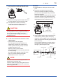
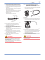
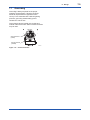
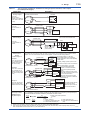
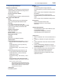
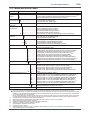
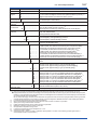
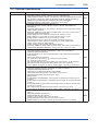
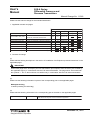
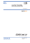
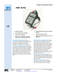
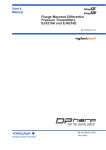
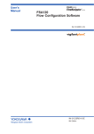
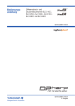
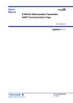
User’s Manual EJX910A and EJX930A Multivariable Transmitters Manual Change No. 11-017 Please use the attached sheets for the page listed below in the following manual. IM 01C25R01-01E (8th) Page and Item Contents of Correction Page 7-5, 7-6 7.6.1 Connecting Shielded Cable with Cable Gland 7.6.3 Removing Shielded Cable with Cable Gland Page 10-5 10.1 Standard Specification Page 10-6, 10-7 10.2 Model and Suffix Codes Page 10-9, 10-10 10.3 Optional Specifications Add the procedure for electrical connection code F (G1/2 female). Change the Specification of “Degree of Protection” and “Name plate and tag”. Add the electrical connection code F, 5 and A. Delete the mounting bracket code G. Update the description. Add the Explosion Protected Optional Specification for EJX930A (FS15, KS2, CF1, SF2). Dec. 9, 2011 Blank Page 7-5 <7. Wiring> PULS E PULS E • Magnified view of the RTD connector in the transmitter's terminal box. SUP PLY SUP PLY K CHEC M ALAR Protection Cap K CHEC M ALAR Connecting Port Procedure (1) Disassemble the cable gland: loosen the running coupler to separate the backnut from the entry. (2) Remove the protection cap over the transmitter electrical connection and install the entry on the electrical connection. Note that a non-hardening sealant should be applied to the threads for a 1/2 NPT connection and a gasket should be used for an M20 connection. F0714.ai PULS E The RTD cable connecting port is covered with a cap to keep out dust. The cap should not be removed until you are ready to install the cable. SUP PLY K CHEC M ALAR CAUTION Input/output signal is non-isolated. Do not turn on power supply until you complete all the wiring work. F0716.ai (3) Pass the RTD cable through the running coupler and backnut assembly. In the case of electrical connection code 2 (1/2NPT female) or 4 (M20 female). • Components for the cable gland The cable gland assembly consists of an entry, seal, running coupler, and backnut. Confirm that the seal is attached inside the entry and that the thread size of the cable gland is the same as that for the RTD electrical connection. F0717.ai (4) Insert the RTD cable and firmly plug its connector into the connecting port in the transmitter's terminal box. 1/2NPT Type Backnut SUPP LY CHECKM ALAR F0718.ai M20 Type Gasket PULS E Running Coupler Entry with Seal Running Coupler Backnut (5) Align the running coupler on the entry. PULS E Entry with Seal SUPP LY CHECKM ALAR F0715.ai F0719.ai IM 01C25R01-01E PULS E (6) Turn the running coupler until the seal in the entry comes into contact with the RTD cable. SUPP LY CHECKM ALAR F0720.ai Procedure (1) Disassemble the cable gland: loosen the all parts (2) Remove the protection cap on the RTD electrical connection and RTD connecting port, and screw the adapter body to the RTD electrical connection. Screw the adapter body into the RTD electrical connection until the O-ring touches the RTD electrical connection (at least 6 full turns), and firmly tighten the lock nut by the wrench. Be sure to apply a non-hardening sealant to the threads for waterproofing. Wrench PULSE (7) Rotate the running coupler another half turn to securely tighten the seal on the RTD cable. (8) Use a protection conduit, if necessary. In this case, insert the cable through the conduit and attach it to the Backnut. CAUTION After the cable is secured as explained above, do not tighten the running coupler any further; to do so could damage the RTD connection. Do not pull the cable or subject it to excessive mechanical shock. 7-6 <7. Wiring> In the case of electrical connection code F (G1/2 female). • Components for the cable gland The cable gland assembly consists of an adapter body, packing box, rubber packing, washer, gland, clamp ring, clamp nut, union coupling, and union cover. Refer to (2) and (3) shown below. RTD cable gland is accompanied by two kinds of rubber packing. Since the outside diameter of the RTD cable is 8.5 mm, use the rubber packing with identification mark “16 8-10” on it. NOTE O-Ring SUPP LY CHECK ALARM Lock nut Adapter body RTD electrical connection F0726.ai (3) Insert the RTD cable in order of a packing box, rubber packing, washer, gland, clamp ring, clamp nut, union coupling, union cover from the cable end of the wire rods side (opposite side of RTD connector). Since the internal diameter of rubber packing has restriction, RTD connector can not pass through it, please keep this order. Lock nut Rubber packing Gland Insertion direction RTD connector Clamp ring Washer Packing box Wrench Clamp nut Union cover Union coupling F0727.ai The RTD cable can not let through the cable gland from the connector side. Insert the cable through the cable gland from the wire rods side (opposite side of RTD connector) before laying the cable. IM 01C25R01-01E 7-7 <7. Wiring> (4) Secure the RTD cable to the packing box by screwing the gland into the packing box at the position where the distance from the connector tip of the RTD cable to the packing box will be 56.5±1mm. Tighten approximately 1 more turn surely after the cable can not move. The quantity of this tightening is very important. It leads to wiring disconnection fault when tighten too much. After that, tighten the clamp nut. 7.6.2 Connecting Shielded Cable for Conduit Use (External temperature input code: -B, -C, and -D) • RTD connection components: EJX multivariable transmitter and RTD cable Rubber packing F0721.ai Gland Procedure (1) Remove the protection cap protecting the RTD electrical connection and insert the RTD cable. Washer Packing box F0728.ai (5) Insert the RTD cable and firmly plug its connector into the connecting port in the transmitter’s terminal box. (6) Screw the union cover to the adaptor body which has fixed to the RTD electrical connection at procedure (2). Screw the union cover at least 6 full turns, and tighten the rock nut. (7) If the conduit piping is necessary, screw the conduit to the union coupling after passing the RTD cable through the conduit. (8) Finally, confirm whether the connector is plugged surely. CAUTION After the cable is plugged as explained above, do not pull the cable or subject it to excessive mechanical shock. Finally, please remember to confirm whether the connector is plugged surely. PULSE 56.5±1 mm SUPP LY CHECK ALARM F0722.ai (2) Remove the cap protecting the connecting port. Then insert the RTD cable and firmly plug the connector into the connecting port in the transmitter's terminal box. (3) Insert the cable through the conduit and attach it to the RTD electrical connection. CAUTION Do not pull the cable or subject it to excessive mechanical shock. IM 01C25R01-01E 7.6.3 Removing Shielded Cable with Cable Gland (External temperature input code: -1, -2, -3, and -4) (1) By pulling out the string attached to the connector, carefully unplug the connector from the transmitter’s connecting port. (2) In the case of using 1/2NPT Type or M20 Type cable gland, remove the running coupler and backnut assembly by turning the running coupler. In the case of using G1/2 Type cable gland, loosen the lock nut screwed into the union cover and remove the union cover. RTD cable can be pulled out together with the packing box. Loosen the clamp nut and the gland if necessary. (3) Pull the RTD cable out carefully. (4) In the case of 1/2NPT Type or M20 Type cable gland, remove the entry from the RTD electrical connection by turning the entry. In the case of G1/2 Type cable gland, loosen the lock nut screwed into the adapter body and remove the adapter body. 7-8 <7. Wiring> NOTE Please note that a temperature error will occur when you use a 2-wire RTD because of wiring resistance. Please do not ground the shield on the RTD side of the cable. CAUTION Please use only the cables provided with this instrument. When wiring, be sure not to damage the cable's insulation or its core. All the cable cores must have sufficient insulation around them. Do not let the signal line contact the shield line. Do not allow the shield line or the signal line to come the earth potential voltage. 2-Wire 3-Wire 4-Wire NOTE In the case of G1/2 Type cable gland, remove the rubber packing, washer, gland, clamp ring, clamp nut, union coupling and union cover from the opposite side of RTD connector in order to take out the cable gland from the RTD cable. A (1) By pulling out the string attached to the connector, slowly unplug the connector from the transmitter's connecting port. (2) Remove the conduit from the RTD electrical connection. (3) Pull the RTD cable out through the RTD electrical connection. 7.6.5 Cable Connection RTD Terminal Box Side EJX multivariable transmitter RTD I/F is for 3-wire Type RTD, Pt100. Heed the following when wiring an RTD of the 2- or 4-wire type. B b F0723.ai Figure 7.11 The Method of Wiring for the RTD Side Table 7.2 7.6.4 Removing Shielded Cable for Conduit Use (External temperature input code: -B, -C, -D) B b Aa B A RTD Terminal 2-Wire 3-Wire 4-Wire The Method of Wiring for the RTD Side RTD Terminal A a B b White White White – – open Blue1 and Blue2 Blue1 Blue1 – Blue2 Blue2 NOTE The color display in the table shows the white line of the cable. The cable color could change depending on the cable type. Blue1 and blue2 allow changing places. For 2-wire Type, connect either which is blue1 or blue2, and give other side as OPEN. IM 01C25R01-01E <7. Wiring> 7-9 7.7 Grounding Grounding is always required for the proper operation of transmitters. Follow the domestic electrical requirements as regulated in each country. For a transmitter with a built-in lightning protector, grounding should satisfy ground resistance of 10Ω or less. PULS E Ground terminals are located on the inside and outside of the terminal box. Either of these terminals may be used. SUPP LY Ground terminal (inside) CHECK ALARM Ground terminal (outside) F0724.ai Figure 7.12 Ground Terminals IM 01C25R01-01E Table 7.1 7-10 <7. Wiring> The connection example for simultaneous analog and pulse and alarm, status output. (For HART protocol type) Output Type Analog Output In this case, Communication is possible (up to a distance of 2km when a CEV cable is used.) Pulse Output In this case, No communication is possible. Description Transmitter Electrical Terminal SUPPLY + PULSE + In this case, No communication is possible. – 24V DC 250Ω – Transmitter Electrical Terminal Shielded Cable SUPPLY Use the Three-wire shielded cable. + + PULSE Status Output Distributor + E – *1 *2 R Electric counter Transmitter Electrical Terminal Use the Three-wire shielded cable. Shielded Cable SUPPLY + PULSE + E Relay – Mognetic valve External Power supply 30V DC, 120mA max (Contact Rating) AC power supply Simultaneous Analog -Pulse Output *3 Example 1 In this case, Communica -tion is possible(up to a distance of 2km when a CEV cable is used). When analog and pulse output are used, the length of communication line is subjected to wiring conditions. Refer to example 1 to 3. If the communication carries out from amplifier, no need to consider wiring conditions. Distributor (or communication medium : ex. EP card) SUPPLY PULSE + + Shielded Cable – 24V DC *2 R Common Transmitter Electrical Terminal Example 2 In this case, Communica -tion is possible (up to a distance of 200m when a CEV cable is used) and R = 1kΩ). Shielded Cable SUPPLY PULSE + + – Transmitter Electrical Terminal SUPPLY PULSE Electric counter *1 (or communication medium : ex. EP card) For the shielded cables in this Recorder or example of flowmeter installation, other instrument use two-wire separately shielded cables. E(16.4 to 30V DC) This supply voltage requires a power *2 R sourse with a maximum output current Counting input of no less than E/R+25mA. Common The supply voltage requires output impedance no more than 1/1000 of R Electric counter *1 (load resistance). 250Ω + – + R*2 E(16.4 to 30V DC) Counting input Common Transmitter Electrical Terminal The range of load resistance R for the pulse output. 250Ω This supply voltage requires a power sourse with a maximum output current of no less than E/R. Recorder or other instrument Example 3 In this case, No communi -cation is possible (when shielded cable is not used). 250Ω E(10.5 to 30V DC) Counting input For the shielded cables in this example of flowmeter installation, use two-wire separately shielded cables. This supply voltage requires a power sourse with a maximum output current of no less than E/R+25mA. Electric counter *1 The load resistance of pulse output should be used to 1kΩ, 2W. If no translation of the pulse output possible by the cable length or the frequency of the pluse output, the load resistance should be selected by calculation as shown below. E (V) 0.1 Example of CEV cable capacitance ≤ R (kΩ) ≤ 0.1µF/km 120 C ( µF ) × f ( kHz ) P (mW) = 2 E (V) R (kΩ) Where E = Supply voltage (V) f = Frequency of pulse output (kHz) R = Value of load resistance (kΩ) C = Cable capacitance (µF) P = Power ratio of the load resistance (mW) *1: To avoid the influence of external noise, use an electric counter which fits to the pulse frequency. *2: Resistor is not necessary in case of an electric counter which can receive contact pulse signal directly. *3: When using analog and pulse output simultaneously, the HART communication may be influenced by noise comparing analog output only. Take countermeasure for noise shown above, e.g. use shield cable etc. F0725.ai IM 01C25R01-01E Normal Operating Condition: (Selected features may affect limits.) Ambient Temperature Limits –40 to 85°C (–40 to 185°F) –30 to 80°C (–22 to 176°F) with LCD display Process Temperature Limits –40 to 120°C (–40 to 248°F) Ambient Humidity Limits 0 to 100% RH EJX930A M and H Capsule 32 MPa (4500 psi) Atmospheric pressure 100(14.5) Applicable range 2.7(0.38) 40 (104) R= E-10.5 0.0244 Digital Communication range 250 R (Ω) 10.5 16.6 25.2 42 F1003.ai Working pressure kPa abs (psi abs) 0 (32) External load resistance Power supply voltage E (V DC) Minimum Pressure Limit See graph below 1(0.14) -40 (-40) Supply & Load Requirements “◊” (Optional features or safety approvals may affect electrical requirements.) With 24 V DC supply, up to a 570 V load can be used. See graph below. 600 Working Pressure Limits (Silicone oil) Maximum Pressure Limits EJX910A L Capsule 16 MPa (2300 psi) M and H Capsule 25 MPa (3600 psi) 10(1.4) 10-4 <10. General Specifications> 80 (176) 120 (248) Process temperature °C (°F) F1002.ai Figure 10.2 Working Pressure and Process Temperature Figure 10.3 Relationship Between Power Supply Voltage and External Load Resistance Supply Voltage 10.5 to 42 V DC for general use and flameproof type. 10.5 to 32 V DC for lightning protector (Option code /A). 10.5 to 30 V DC for intrinsically safe, type n or nonincendive. Minimum voltage limited at 16.4 V DC for HART communication. Load (Output signal code E) 0 to 1335Ω for operation 250 to 600Ω for digital communication EMC Conformity Standards, , EN61326-1 Class A, Table2 (For use in industrial locations) EN61326-2-3 IM 01C25R01-01E Physical Specifications Wetted Parts Materials Diaphragm, Cover Flange, Process Connector, Capsule Gasket, and Vent/Drain Plug Refer to “Model and Suffix Code.” Process Connector Gasket PTFE Teflon Fluorinated rubber for Option code /N2 and /N3 Non-wetted Parts Materials Bolts ASTM-B7 carbon steel, 316L SST stainless steel, or ASTM grade 660 stainless steel Housing Low copper cast aluminum alloy with polyurethane, mint-green paint (Munsell 5.6BG 3.3/2.9 or its equivalent) or ASTM CF-8M stainless steel Degrees of Protection IP66, IP67, NEMA4X Cover O-rings Buna-N, fluoro-rubber (option) Name plate and tag 316 SST Fill Fluid Silicone oil, Fluorinated oil (option) Cable for RTD External Temperature Input Code -1, -2, -3, -4 Oil-proof and a heat-resistant cable with a shield Outside diameter: 8.5 mm (0.335 inch), Voltage rating: 300V Temperature rating: –40 to 105°C (–40 to 221°F) External Temperature Input Code -B,-C,-D A heat-resistant FEP cable with a shield Outside diameter: 4.3mm (0.168 inch) Voltage rating: 300V Temperature rating: –80 to 200°C (–112 to 392°F) Flame resistance: NEC Article 800-CMP Adaptation standard: NEC Article 725-PLTC 10-5 <10. General Specifications> Weight [EJX910A] 2.8 kg (6.2 lb) without integral indicator, mounting bracket, process connector and RTD cable. Add 1.5 kg (3.3 lb) for Amplifier housing code 2. [EJX930A] 6.8 kg (14.3 lb) without integral indicator, mounting bracket, process connector and RTD cable. Add 1.5 kg (3.3 lb) for Amplifier housing code 2. Connections Refer to “Model and Suffix Code.” Process Connection of Cover Flange: IEC61518 < Related Instruments> Power Distributor: Refer to GS 01B04T01-02E or GS 01B04T02-00E FSA120 Flow Configuration Software (FlowNavigator) GS 01C25R51-01E < Reference > 1. Teflon; Trademark of E.I. DuPont de Nemours & Co. 2. Hastelloy; Trademark of Haynes International Inc. 3. HART; Trademark of the HART Communication Foundation. 4. AIChE, DIPPR (Design Institute for Physical Properties); Trademarks of American Institute of Chemical Engineers. 5. AGA; Trademark of American Gas Association. Other company/organization names and product names used in this material are registered trademarks or trademarks of their respective owners. Note for using an extension cable: When extending a temperature cable with using an extension cable and a junction box, total cable length including the original external temperature cable must be less than 25 m. Use PE or XLPE insulated cable for extension. Cable gland Nickel plating brass IM 01C25R01-01E <10. General Specifications> 10-6 10.2 Model and Suffix Codes Model EJX910A Output signal Suffix Codes ...................... -E . . . . . . . . . . . . . . . . . . . . . -J . . . . . . . . . . . . . . . . . . . . . -F . . . . . . . . . . . . . . . . . . . . . Measurement L . . . . . . . . . . . . . . . . . . . span (capsule) M . . . . . . . . . . . . . . . . . . . H . . . . . . . . . . . . . . . . . . . Wetted parts S . . . . . . . . . . . . . . . . . material *1 Process 0 . . . . . . . . . . . . . . . connections 1 . . . . . . . . . . . . . . . 2 . . . . . . . . . . . . . . . 3 . . . . . . . . . . . . . . . 4 . . . . . . . . . . . . . . . ► 5 . . . . . . . . . . . . . . . Bolts and nuts J . . . . . . . . . . . . . material G . . . . . . . . . . . . . C . . . . . . . . . . . . . -7 . . . . . . . . . . . . Installation -8 . . . . . . . . . . . . ► -9 . . . . . . . . . . . . -B . . . . . . . . . . . . 1 . . . . . . . . . . 2 . . . . . . . . . . Electrical connection F . . . . . . . . 2 . . . . . . . . 4 . . . . . . . . 5 . . . . . . . . 7 . . . . . . . . 9 . . . . . . . . A . . . . . . . . C . . . . . . . . D . . . . . . . . Integral indicator D . . . . . . ► N . . . . . . Mounting bracket B . . . . . D . . . . . J . . . . . K . . . . . M . . . . . ► N . . . . . External temperature input *3 -0 . . . . -1 . . . . -2 . . . . -3 . . . . -4 . . . . -B . . . . -C . . . . -D . . . . Measurement function A . . . ► B . . . Optional codes Amplifier housing Description Multivariable transmitter 4 to 20 mA DC with digital communication (HART protocol)*8 4 to 20 mA DC with digital communication (HART 5/HART 7 protocol)*9 Digital communication (FOUNDATION Fieldbus protocol) 0.1 to 10 kPa (0.4 to 40 inH2O) 0.5 to 100 kPa (2 to 400 inH2O) 2.5 to 500 kPa (10 to 2000 inH2O) Refer to Table 10.3 without process connector (Rc1/4 female on the cover flanges) with Rc1/4 female process connector with Rc1/2 female process connector with 1/4 NPT female process connector with 1/2 NPT female process connector without process connector (1/4 NPT female on the cover flanges) ASTM-B7M carbon steel 316L SST (ISO A4-70) stainless steel ASTM grade 660 stainless steel Vertical piping, left side high pressure, and process connection downside Horizontal piping and right side high pressure Horizontal piping and left side high pressure Bottom Process Connection, left side high pressure Cast alluminum alloy ASTM CF-8M Stainless steel G 1/2 female, two electrical connections (One connection for RTD) 1/2NPT female, two electrical connections (One connection for RTD) M20 female, two electrical connections (One connection for RTD) G 1/2 female, two electrical connections and a blind plug *2*6*7 1/2NPT female, two electrical connections and a blind plug *2*6*7 M20 female, two electrical connections and a blind plug *2*6*7 G 1/2 female, two electrical connections and a 316 SST blind plug *2 1/2 NPT female, two electrical connections and a 316 SST blind plug *2 M20 female, two electrical connections and a 316 SST blind plug *2 Digital indicator None 304 SST 2-inch pipe mounting, flat type (for horizontal piping) 304 SST 2-inch pipe mounting, L type (for vertical piping) 316 SST 2-inch pipe mounting, flat type (for horizontal piping) 316 SST 2-inch pipe mounting, L type (for vertical piping) 316 SST 2-inch pipe mounting (for bottom process connection type) None Fixed temperature (without cable) *5 RTD input with 0.5 m (1.64 ft) of shielded cable and two cable glands *7 RTD input with 4 m (13.1 ft) of shielded cable and two cable glands *7 RTD input with 7.5 m (24.6 ft) of shielded cable and two cable glands *7 RTD input with 25 m (81 ft) of shielded cable and two cable glands *7 RTD input with 4 m (13.1 ft) of shielded cable without cable gland *4 RTD input with 7.5 m (24.6 ft) of shielded cable without cable gland *4 RTD input with 25 m (81 ft) of shielded cable without cable gland *4 Multi Sensing (DP, P and T) Mass Flow Measurement (Flow, DP, P and T) / Optional specification The “►” marks indicate the most typical selection for each specification. *1: Users must consider the characteristics of selected wetted parts material and the influence of process fluids. The use of inappropriate materials can result in the leakage of corrosive process fluids and cause injury to personnel and/or damage to plant facilities. It is also possible that the diaphragm itself can be damaged and that material from the broken diaphragm and the fill fluid can contaminate the user’s process fluids. Be very careful with highly corrosive process fluids such as hydrochloric acid, sulfuric acid, hydrogen sulfide, sodium hypochlorite, and high-temperature steam (150°C [302°F] or above). Contact Yokogawa for detailed information of the wetted parts material. *2: For External Temperature Input code 0 (Fixed temperature) . *3: Recommended External Temperature Input Cable is as shown in Table 10.2. RTD is not provided. *4: Specify when using conduit for RTD connection. *5: Preset external temperature value is used for density compensation. *6: Material of a blind plug is aluminum alloy or 304 SST. *7: Not applicable for Amplifier housing code 2. *8: Output signal code E: HART 5. *9:Output signal code J: HART 5 or HART 7 selectable. Specify HART 5 or HART 7 when ordering. (Output signal code J is recommended for HART communication.) IM 01C25R01-01E Model EJX930A Suffix Codes ...................... -E . . . . . . . . . . . . . . . . . . . . . Output -J . . . . . . . . . . . . . . . . . . . . . signal -F . . . . . . . . . . . . . . . . . . . . . Measurement M . . . . . . . . . . . . . . . . . . . span (capsule) H . . . . . . . . . . . . . . . . . . . S . . . . . . . . . . . . . . . . . Wetted parts material *1 3 . . . . . . . . . . . . . . . Process 4 . . . . . . . . . . . . . . . connections ► 5 . . . . . . . . . . . . . . . J . . . . . . . . . . . . . Bolts and nuts G . . . . . . . . . . . . . material C . . . . . . . . . . . . . -7 . . . . . . . . . . . . Installation -8 . . . . . . . . . . . . ► -9 . . . . . . . . . . . . 1 . . . . . . . . . . Amplifier housing 2 . . . . . . . . . . <10. General Specifications> 10-7 Description Multivariable transmitter 4 to 20 mA DC with digital communication (HART protocol) *9 4 to 20 mA DC with digital communication (HART 5/HART 7 protocol) *10 Digital communication (FOUNDATION Fieldbus protocol) 1 to 100 kPa (4 to 400 inH2O) 5 to 500 kPa (20 to 2000 inH2O) Refer to Table 10.3 with 1/4 NPT female process connector *8 with 1/2 NPT female process connector *8 without process connector (1/4 NPT female on the cover flanges) ASTM-B7 carbon steel 316L SST stainless steel ASTM grade 660 stainless steel Vertical piping, left side high pressure, and process connection downside Horizontal piping and right side high pressure Horizontal piping and left side high pressure Cast alluminum alloy ASTM CF-8M Stainless steel G 1/2 female, two electrical connections (One connection for RTD) 1/2NPT female, two electrical connections (One connection for RTD) M20 female, two electrical connections (One connection for RTD) G 1/2 female, two electrical connections and a blind plug *2*6*7 1/2NPT female, two electrical connections and a blind plug *2*6*7 M20 female, two electrical connections and a blind plug *2*6*7 G 1/2 female, two electrical connections and a 316 SST blind plug *2 1/2 NPT female, two electrical connections and a 316 SST blind plug *2 M20 female, two electrical connections and a 316 SST blind plug *2 F . . . . . . . . 2 . . . . . . . . 4 . . . . . . . . 5 . . . . . . . . 7 . . . . . . . . 9 . . . . . . . . A . . . . . . . . C . . . . . . . . D . . . . . . . . D . . . . . . Integral indicator ► N . . . . . . B . . . . . Mounting bracket D . . . . . J . . . . . K . . . . . ► N . . . . . -0 . . . . External temperature input *3 -1 . . . . -2 . . . . -3 . . . . -4 . . . . -B . . . . -C . . . . -D . . . . A . . . Measurement function ► B . . . Digital indicator None 304 SST 2-inch pipe mounting, flat type (for horizontal piping) 304 SST 2-inch pipe mounting, L type (for vertical piping) 316 SST 2-inch pipe mounting, flat type (for horizontal piping) 316 SST 2-inch pipe mounting, L type (for vertical piping) None Fixed temperature (without cable) *5 RTD input with 0.5 m (1.64 ft) of shielded cable and two cable glands *7 RTD input with 4 m (13.1 ft) of shielded cable and two cable glands *7 RTD input with 7.5 m (24.6 ft) of shielded cable and two cable glands *7 RTD input with 25 m (81 ft) of shielded cable and two cable glands RTD input with 4 m (13.1 ft) of shielded cable without cable gland *4 RTD input with 7.5 m (24.6 ft) of shielded cable without cable gland *4 RTD input with 25 m (81 ft) of shielded cable without cable gland *4 Multi Sensing (DP, P and T) Mass Flow Measurement (Flow, DP, P and T) Optional codes / Electrical connection Optional specification The “►” marks indicate the most typical selection for each specification. *1: Users must consider the characteristics of selected wetted parts material and the influence of process fluids. The use of inappropriate materials can result in the leakage of corrosive process fluids and cause injury to personnel and/or damage to plant facilities. It is also possible that the diaphragm itself can be damaged and that material from the broken diaphragm and the fill fluid can contaminate the user’s process fluids. Be very careful with highly corrosive process fluids such as hydrochloric acid, sulfuric acid, hydrogen sulfide, sodium hypochlorite, and high-temperature steam (150°C [302°F] or above). Contact Yokogawa for detailed information of the wetted parts material. *2: For External Temperature Input code 0 (Fixed temperature) . *3: Recommended External Temperature Input Cable is as shown in Table 10.2 RTD is not provided. *4: Specify when using conduit for RTD connection. *5: Preset external temperature value is used for density compensation. *6: Material of a blind plug is aluminum alloy or 304 SST. *7: Not applicable for Amplifier housing code 2. *8: Lower limit of ambient and process temperature is –15°C. *9: Output signal code E: HART 5. *10: Output signal code J: HART 5 or HART 7 selectable. Specify HART 5 or HART 7 when ordering. (Output signal code J is recommended for HART communication.) IM 01C25R01-01E Table 10.2 Recommended External Temperature Cable External Temperature Input Code General Application Factory Mutual (FM) Nonincendive Explosionproof Approval Intrinsically safe Approval CENELEC ATEX Type N Flameproof Approval Intrinsically safe Approval Canadian Standards Association (CSA) Explosionproof Approval IECEx Scheme Explosionproof Approval Table. 10.3 10-8 <10. General Specifications> -1, -2, -3, -4 -B, -C, -D Wetted Parts Materials [EJX910A] Wetted parts material code Cover flange and process connector S# ASTM CF-8M*1 Capsule Capsule gasket Drain/Vent plug Hastelloy C-276 *2 (Diaphragm) F316L SST (Others) Teflon-coated 316L SST 316 SST Capsule gasket Drain/Vent plug [EJX930A] Wetted parts material code Cover flange Process connector S# F316 SST ASTM CF-8M *1 Capsule Hastelloy C-276 *2 (Diaphragm) Teflon-coated 316L SST F316L SST (Others) 316 SST *1: Cast version of 316 SST. Equivalent to SCS14A. *2: Hastelloy C-276 or N10276. The ‘#’marks indicate the construction materials conform to NACE material recommendations per MR01-75. For the use of 316 SST material, there may be certain limitations for pressure and temperature. Please refer to NACE standards for details. IM 01C25R01-01E 10-9 <10. General Specifications> 10.3 Optional Specifications Item Factory Mutual (FM) CENELEC ATEX Description FM Explosionproof Approval *4 Applicable Standard: FM3600, FM3615, FM3810, ANSI/NEMA 250 Explosionproof for Class I, Division 1, Groups B, C and D, Dust-ignitionproof for Class II/III, Division 1, Groups E, F and G, in Hazardous locations, indoors and outdoors (NEMA 4X) “FACTORY SEALED, CONDUIT SEAL NOT REQUIRED.” Temperature class: T6, Amb. Temp.: –40 to 60°C (–40 to 140°F)*2 FM Intrinsically Safe and Nonincendive Approval *3 *4 Applicable Standard: FM3600, FM3610, FM3611, FM3810, ANSI/NEMA 250, IEC60079-27 Intrinsically Safe for Class I,II, & III, Division 1, Groups A,B,C,D,F & G, Entity, FISCO. Class I, Zone 0, AEx ia IIC, Enclosure: "NEMA 4X", Temp. Class: T4, Amb. Temp.: –40 to 60°C (–40 to 140°F). *2 Intrinsically Apparatus Parameters: [FISCO (IIC)] Ui=17.5 V, Ii=380 mA, Pi=5.32 W, Ci=3.52 nF, Li=0 μH [FISCO (IIB)] Ui=17.5 V, Ii=460 mA, Pi=5.32 W, Ci=3.52 nF, Li=0 μH [Entity] Ui=24 V, Ii=250 mA, Pi=1.2 W, Ci=3.52 nF, Li=0 μH Sensor Circuit: Uo=6.51 V, Io=4 mA, Po=6 mW, Co=34 μF, Lo=500 mH Nonincendive for Class I, Division 2, Groups A, B, C and D, NIFW, FNICO Class I, Zone 2, Group IIC, NIFW, FNICO Class II, Division 2, Groups F&G, and Class III, Division 1 Enclosure: "NEMA 4X", Temp. Class: T4, Amb. Temp.: –40 to 60°C (–40 to 140°F) *2 Nonincendive Apparatus Parameters : Vmax.= 32 V, Ci = 1.76 nF, Li = 0 μH CENELEC ATEX (KEMA) Flameproof Approval *4 Applicable Standard: EN 60079-0, EN 60079-1, EN 61241-0, EN 61241-1 Certificate: KEMA 07ATEX0109 II 2G, 2D Exd IIC T4, T5, T6 Ex tD A21 IP6X T85, T100, T120 Degree of protection: IP66 and IP67 Amb. Temp. (Tamb) for gas-proof: T4; –50 to 75°C (–58 to 167°F), T5; –50 to 80°C (–58 to 176°F), T6; –50 to 75°C (–58 to 167°F) *2 Max. process Temp.(Tp): T4; 120°C (248°F), T5; 100°C (212°F), T6; 85°C (185°F) Max. surface Temp. for dust-proof: T85°C (Tamb: –40 to 40°C, Tp:85°C), T100°C (Tamb: –40 to 60°C, Tp:100°C), T120°C (Tamb: –40 to 80°C, Tp:120°C) *2 CENELEC ATEX (KEMA) Intrinsically safe Approval *1 *4 Applicable Standard: EN 50014, EN 50020, EN 50284, EN 50281-1-1 Certificate: KEMA 06ATEX0037X II 1G, 1D EEx ia IIC T4 Degree of protection: IP66 and IP67 Amb. Temp. (Tamb) for gas-proof: –50 to 60°C (–58 to 140°F) *2 Maximum Process Temp.(Tp) for gas-proof: 120°C Electrical data: [Supply/Output circuit (terminals + and –)] Ui=30 V, Ii=200 mA, Pi=0.9 W, Ci=10 nF, Li=0 mH [Pulse Output circuit (terminals – and pulse)] Ui=30 V, Ii=200 mA, Pi=0.9 W, Ci=10 nF, Li=0 mH [External Temperature Input circuit (connector)] Uo=30 V, Io=95.4 mA, Po=468 mW, Co=11 nF, Lo=3.9 mH Max. surface Temp. for dust-proof: T85°C (Tamb: –40 to 60°C, Tp: 80°C), T100°C (Tamb: –40 to 60°C, Tp: 100°C), T120°C (Tamb: –40 to 60°C, Tp: 120°C) *2 Combined KF21, KS2 and Type n *1 *4 *5 Type n Applicable Standard: EN 60079-15 Referential Standard: IEC 60079-0 II 3G Ex nL IIC T4, Amb. Temp.: –50 to 60 deg C *2 [Supply and Pulse circuit] Ui=30 V DC, Ci=10 nF, Li=0 mH [Sensor circuit] Uo=7.4 V DC, lo=25 mA, Po=46.3 mW, Co=11 nF, Lo=3.9 mH Code FF1 FS15 KF21 KS2 KU21 IM 01C25R01-01E Item CENELEC ATEX 10-10 <10. General Specifications> Description CENELEC ATEX (KEMA) Intrinsically safe Approval *3 *4 *5 Applicable standards: EN 60079-0:2006, EN 50020:2002, EN 60079-27:2006, EN 50284:1999, EN 50281-1-1:1998+A1 Certificate: KEMA 06ATEX0278X II 1GD Ex ia IIB/IIC T4 Degree of protection: IP66 and IP67 Amb. Temp.: –40 to 60°C (–40 to 140°F) *2 Max. Process Temp. (Tp): 120°C (248°F) Electrical data: Supply/Output circuit (terminals + and –) [FISCO (IIC)] Ui=17.5 V, Ii=380 mA, Pi=5.32 W, Ci=1.76 nF, Li=0 μH [FISCO (IIB)] Ui=17.5 V, Ii=460 mA, Pi=5.32 W, Ci=1.76 nF, Li=0 μH [Entity] Ui=24 V, Ii=250 mA, Pi=1.2 W, Ci=1.76 nF, Li=0 μH External Temperature Input circuit (connector) Uo=7.63 V, Io=3.85 mA, Po=8 mW, Co=4.8 μF, Lo=100 mH Max. Surface Temp. for dust-proof: T85°C (Tp:80°C), T100°C (Tp:100°C), T120°C (Tp:120°C) Canadian Standards CSA Explosionproof Approval *4 Association (CSA) Certificate: 2014354 Applicable Standard: C22.2 No.0, C22.2 No.0.4, C22.2 No.0.5, C22.2 No.25, C22.2 No.30, C22.2 No.94, C22.2 No.60079-0, C22.2 No.60079-1, C22.2 No.61010-1-04 Explosion-proof for Class I, Groups B, C and D. Dustignition-proof for Class II/III, Groups E, F and G. When installed in Division 2, “SEAL NOT REQUIRED” Enclosure: TYPE 4X, Temp. Code: T6...T4 Ex d IIC T6...T4 Enclosure: IP66 and IP67 Max.Process Temp.: T4;120°C (248°F), T5; 100°C (212°F), T6; 85°C (185°F) Amb.Temp.: –50 to 75°C (–58 to 167°F) for T4, –50 to 80°C (–58 to 176°F) for T5, –50 to 75°C (–58 to 167°F) for T6 *2 Process Sealing Certification Dual Seal Certified by CSA to the requirement of ANSI/ISA 12.27.01 No additional sealing required Primary seal failure annuniciation: at the zero adjustment screw CSA Intrinsically safe Approval *1 *6 IECEx Scheme IECEx Flameproof Approval *4 Applicable Standard: IEC 60079-0:2004, IEC60079-1:2003 Certificate: IECEx CSA 07.0008 Flameproof for Zone 1, Ex d IIC T6...T4 Enclosure: IP66 and IP67 Max.Process Temp.: T4;120°C (248°F), T5;100°C (212°F), T6; 85°C (185°F) Amb.Temp.: –50 to 75°C (–58 to 167°F) for T4, –50 to 80°C (–58 to 176°F) for T5, –50 to 75°C (–58 to 167°F) for T6 *2 Code KS25 CF1 — SF2 Contact Yokogawa representative for the codes indicated as ‘—’ *1: Not Applicable for output signal code -F. *2: Lower limit of ambient temperature is –15°C(5°F) when /HE is specified. *3: Not Applicable for output signal code -E and J. *4: Applicable for electrical connection code 2, 4, 7, 9, C and D. *5: Not Applicable for EJX930A. *6: Pending IM 01C25R01-01E <10. General Specifications> Item Description Painting Color change Coating change 316 SST exterior parts Fluoro-rubber O-ring Lightning protector Oil-prohibited use *2 Oil-prohibited use with dehydrating treatment *2 Capsule fill fluid Calibration units *3 Gold-plated diaphragm Long vent *4 Output limits and failure operation *5 Body option*6 Terminal Side L H 10-11 F1004.ai Stainless steel tag plate Data configuration at factory *7 PID function *15 Advanced diagnostics Software downloading function *15 European Pressure Equipement Directive *16 Material certificate *8 Pressure test Leak test certificate *11 Code Amplifier cover only P PR Amplifier cover and terminal cover, Munsell 7.5 R4/14 Anti-corrosion coating*1 X2 316 SST name plate, tag plate and zero-adjustment screw*17 All O-rings of amplifier housing. Lower limit of ambient temperature: –15°C(5°F) Transmitter power supply voltage: 10.5 to 32 V DC Allowable current: Max. 6000 A (1×40 µs), Repeating 1000 A (1×40 µs) 100 times Applicable Standards: IEC 61000-4-4, IEC 61000-4-5 Degrease cleansing treatment Degrease cleansing treatment with fluorinated oilfilled capsule. Operating temperature –20 to 80°C( –4 to 176°F) Degrease cleansing and dehydrating treatment Degrease cleansing and dehydrating treatment with fluorinated oilfilled capsule. Operating temperature –20 to 80°C( –4 to 176°F) Fluorinated oil filled in capsule Operating temperature –20 to 80°C( –4 to 176°F) P calibration (psi unit) (See Table for Span and Range bar calibration (bar unit) Limits.) 2 M calibration (kgf/cm unit) Surface of isolating diaphragm is gold plated, effective for hydrogen permeation. Total length: 119 mm (standard: 34 mm); Total length when combining with option code K1, K2, K5, and K6: 130 mm. Material: 316 SST Failure alarm down-scale: Output status at CPU failure and hardware error is –2.5%, 3.6 mA DC or less. NAMUR NE43 Compliant Failure alarm down-scale: Output status at CPU failure Output signal limits: and hardware error is –2.5%, 3.6 mA DC or less. 3.8 mA to 20.5 mA Failure alarm up-scale: Output status at CPU failure and hardware error is 110%, 21.6 mA or more. Right side high pressure, without drain and vent plugs N1 and Process connection, based on IEC61518 with female thread on both sides of cover flange, with blind kidney flanges on back. N2, and Material certificate for cover flange, diaphragm, capsule body, and blind kidney flange HC HE 304 SST tag plate wired onto transmitter (316 SST when/HC is specified) Software damping, Data configuration for HART communication type Descriptor, Message Data configuration for Fieldbus communication type Software damping PID control function Multi-sensing process monitoring HART communication type • Impulse line blockage detection *19 Fieldbus communication type *18 • Heat trace monitoring Based on FOUNDATION Fieldbus Specification (FF-883) Download class: Class1 N4 A K1 K2 K5 K6 K3 D1 D3 D4 A1 U1 C1 C2 C3 N1 N2 N3 CA CC LC1 DG6 DG1 EE PED 97/23/EC Category III, Module H, type of equipment: Pressure accessory-vessel, PE3 Tupe of fluid: Liquid and Gas, Group of fluid: 1 and 2 Lower limit of Process and Ambient temperature for EJX910A: –29°C M01 Cover flange *9 M11 Cover flange, Process connector *10 *14 T12 Test Pressure: 16 MPa (2300 psi) *12 Nitrogen (N2) Gas *13 Retention time: one minute T13 Test Pressure: 25 MPa (3600 psi) Test Pressure: 32 MPa (4500 psi) *21 Nitrogen (N2) Gas or Water *20 T09 Retention time: one minute IM 01C25R01-01E EJX-A Series Differential Pressure and Pressure Transmitters User’s Manual Manual Change No. 11-018 Please use this manual change for the manuals listed below. 1. Applicable manuals and pages Applicable item in 2 (1) (2) (3) (4) (5) Page Page Page Page Page 2-3 9-4 9-5 to 9-10 EJX210A 2-3 9-4 9-5 EJX510A, EJX530A, EJX610A, EJX630A 2-3 9-4 9-5 and 9-6 EJX118A and EJX438A EJX115A 2-3 8-4 8-5 and 8-6 IM 01C25K01-01E (3rd) 2-3 9-3 9-4 IM 01C25R01-01E (8th) EJX910A and EJX930A 3-3 10-4 IM 01C25R03-01E (7th) EJX910A Fieldbus Communication Type 2-1 A-39 IM 01C25T02-01E (10th) EJX series Fieldbus Communication Type 2-1 A4-4 IM No. and Edition Products IM 01C25B01-01E (10th) EJX110A, EJX120A, EJX130A, EJX310A, EJX430A and EJX440A IM 01C25C01-01E (7th) IM 01C25F01-01E (7th) IM 01C25H01-01E (6th) 10-5 and 10-6 2. Contents of Change (1) Please add the follwing descriptions in the section of "Installation of an Explosion-protected Instrument" in the applicable pages. IMPORTANT All the blind plugs which accompany the EJX transmitters upon shipment from the factory are certified by the applicable agency in combination with the EJX series transmitters. The plugs which are marked with the symbols "䉫 Ex" on their surfaces are certified only in combination with the EJX series transmitters. (2) Please use the following information in place of the corresponding part on the applicable pages. Nameplate and tag 316SST (including /N4 wired tag) (3) Please add the following information in the corresponding part of the table on the applicable pages. Amplifier Housing 3 ...................... Cast aluminum alloy with corrosion resistance properties December 12, 2011 Yokogawa Electric Corporation (4) Please add the following information in the corresponding part of the table on the applicable pages. Electrical connection F ...................... 5 ...................... A ...................... G1/2 female, two electrical connections (One connection for RTD) G1/2 female, two electrical connections and a blind plug*2*6*7 G1/2 female, two electrical connections and a 316SST blind plug*2 (5) Please use the following information in place of the description of "10) Polynominal computation" on the applicable pages. 10) Polynominal computation func = PV + GAIN_IN_1 PV2 + GAIN_IN_2 PV3 + GAIN_IN_3 PV4