1
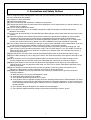
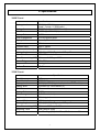
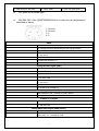
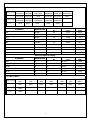
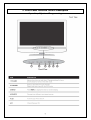
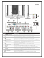
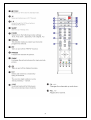
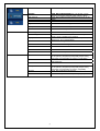
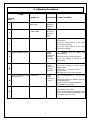
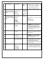
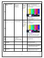
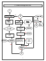
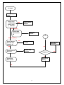
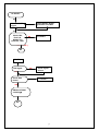
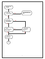
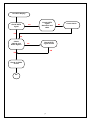
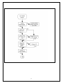
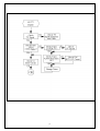
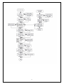
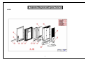
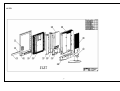
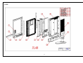
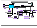
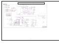
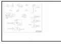
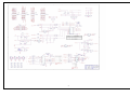
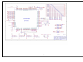
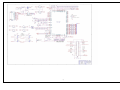
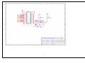
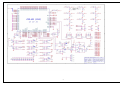
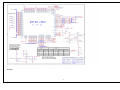
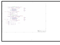
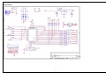
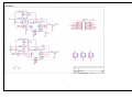
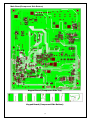
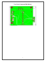
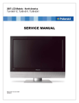
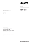
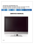
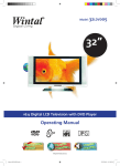
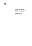
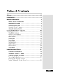
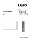
□ 系 統 文 件
SUBJECT:
(主旨)
JL328/378/408-XP
Service Manual
▓ 第一類支援文件
MODEL NO: JL328/378/408-XP
(機種)
REVISION: A1
(文件版本)
DOC.NO:
(文件編碼)
PAGE 1 OF 56
EFFECTIVE DATE:
(生效日期)
發行一日後生效
(變更記錄)
變更次數
COPY TO
收文單位
變
更
內
容
All CONTENTS
(全 文)
APPROVED BY/核准 CONCURRED BY/會簽
RD(电子部)
REVIEWED BY/審核
PREPARED BY/擬稿
□ 第二類支援文件
RD(机构课)
技术支援课
REVISION STATUS
(內文版本)
PAGE
1
2
3
4
5
6
7
8
9
10
11
12
13
14
15
16
17
18
19
20
21
…
55
56
REV.
A1
A1
A1
A1
A1
A1
A1
A1
A1
A1
A1
A1
A1
A1
A1
A1
A1
A1
A1
A1
A1
A1
A1
A1
JL328/378/408-XP
Service Manual
2
TABLE OF CONTENTS
1.
Precautions and Safety Notices ································· 4
2.
Specification ················································· 5
3.
Front Panel Function Control Description ························· 12
4.
Adjusting Procedure ········································· 18
5.
Trouble Shooting Flow Chart ·································· 22
6.
Exploded Diagram and Spare Parts List ·························· 32
7. Block Diagrams ·········································································37
8. Schematic Diagrams
·····························································38
9. PCB Layout Diagrams ·········································55
3
1. Precautions and Safety Notices
Prior to using this service manual,please ensure that you have carefully followed all the procedures outlined in
the user's manual for this product.
(1) Read all of these instructions.
(2) Save these instructions.
(3) Follow all warnings and instructions a marked on the product.
(4) Unplug this product from the wall outlet before cleaning.Do not use liquid cleaners or aerosol cleaners, use
a damp cloth for cleaning.
(5) Do not use this product near water.
(6) Do not place this product on an unstable cart,stand or tablle.The product may fall,causing serious
damage to the product.
(7) Do not tear up the EMI label, if the label has been destroyed,that must to past same size label on the same
position.
(8) Slots and openings in the cabinet and the back or bottom are provided for ventilation,to ensure reliable
operation of the product and to protect it from overheating,those openings must not be blocked or
covered.The openings should never be blocked by placing the product on a bed,sofa, rug, or other similar
surface.This product should not be placed in a built-in installation less proper ventilation is provided.
(9) This products should be operated from the type of power source indicated on the marketin label. If you are
not sure of the type of power available, consult your dealer or local power company
(10) This product is equipped with a 3-wire grounding type plug,a plug having a third (grounding) pin. This
plug will only fit into a grounding-type power outlet. This is a safety feature, if you are unable to insert the
plug into the outlet, contact your electrician to replace your obsolete outlet. Do not defeat the purpose of
the grounding-type plug.
(11) Pay attention to the code which connects with apheliotropism board of inside panel.and don’t hook it.
(12) Do not allow anything to rest on the power cord.Do not locate this product where persons will walk on the
cord.
(13) If an extension cord is used with this product,make sure that the total of the ampere ratings on the
product plugged into the extension cord to the waplugged into outlet does not exceed 15 ampere.
(14) Never push objects of any kind into this product through cabinet slots as they may touch dangerous
voltage points or short out parts that could result in a risk of fire or electric shock.Never spill liquid of any
kind on the product.
(15) Do not attempt to service this product yourself,as opening or removing covers may expose you to
dangerous voltage points or other risks.Refer all servicing to service personnel.
(16) Unplug this product from the wall outlet and refer servicing to qualified service personnel under the
following conditions :
a. When the power cord or plug is damaged or frayed.
b. If liquid has been spilled into the product.
c. If the product has been exposed to rain or water.
d. If the product does not operate normally,when the operating instructions are followed.Adjust only those
controls that are covered by the operating instructions since improper adjustment of other controls may
result in damage and will often require extension work by a qualified technician to restore the product to
normal operation.
e. If the product has been dropped or the cabinet has been damaged.
f. If the product exhibits a distinct change in performance,indicating a need for service.
4
2. Specification
328XP Panel
Item
Display pixels
Display Area
Specifications
1366 (H) x 768 (V)
pixels ( 1 pixel = 1 RGB cells )
708.954mm(H) x 398.592mm (V)
Pixel Pitch
0.1730 (H) x 0.5190 (V)mm
Display Colors
16.7M
Pixel Arrangement
R+G+B vertical stripe
Display Mode
Normally Black Mode
Brightness
550nits
Contrast Ratio
1000:1 typical
Brightness Uniformity
75% min.
Viewing Angle
±88° (H), ±88°(V) Typical at CR ≧ 20
Color Saturation
NTSC 75%
Color Chromaticity (CIE) White: x =0. 285 , y= 0.293
Frame Rate
50Hz/60Hz
Response Time
8ms typical
Surface Treatment
AG,3H
378XP Panel:
Item
Panel Name
Panel Model No.
Display pixels
Specifications
AUO
T370XW01
1366 (H) x 768 (V) pixels ( 1 pixel = 1 RGB cells )
Display Area
819.6mm (H) x 460.89mm (V)
Pixel Pitch
0.6mm
Display Colors
16.7M
Pixel Arrangement
R+G+B vertical stripe
Brightness
500nits typical
Contrast Ratio
1000:1 typical
±88° (H), ±88°(V) Typical at CR ≧ 10
Color Chromaticity (CIE) White: x= 0.280 , y =0. 290
Viewing Angle
Response Time
8ms (Gray to Gray)
Surface Treatment
Hard-Coating (3H), Anti-Glare, Reflectance < 2%
5
408XP Panel:
Item
Panel Name
Display pixels
Specifications
SAMSUNG
1366 (H) x 768 (V) pixels ( 1 pixel = 1 RGB cells )
Display Area
885.168mm (H) x 497.664mm (V)
Display Colors
16.7M
Pixel Arrangement
R+G+B vertical stripe
Brightness
500nits typical
Contrast Ratio
1200:1 typical
±89° (H), ±89°(V) Typical at CR ≧ 10
Color Chromaticity (CIE) White: x= 0.280 , y =0. 290
Viewing Angle
Response Time
8ms (Gray to Gray)
Surface Treatment
Haze 40%, Hard-Coating (3H)
6
INPUT Source :
Inputs & Outputs Signals
Video Format
Connector types
Video
PH Type
Sound
Main-TV
PAL/ SECAM
None
RGB+Y/C+
CVBS(input/output)+
RGB+Y/C+
CVBS(input/output)+
L/R(input/output)
L/R(input/output)
RGB+Y/C+
CVBS(input/output)+
L/R(input/output)
RGB+Y/C+CVBS(input
/output)+L/R(input/outp
ut)
Video1 + L/R Audio
CVBS
RCA x 1
RCA x 2(Red, White)
Video2 + L/R Audio
CVBS
RCA x 1
RCA x 2(Red, White)
S-VIDEO+ L/R Audio
Y/C
Mini Din 4 Pin
RCA x 2(Red, White)
Component1(Y,Pb/Cb,,
Pr/Cr) + L/R Audio
480i.576i.480p,576p.7 RCA x 3
20p, 1080i
RCA x 2(Red, White)
Component2(Y,Pb/Cb2,,
Pr/Cr2) + L/R Audio
480i.576i.480p,576p.7 RCA x 3
20p, 1080i
RCA x 2(Red, White)
VGA+ L/R Audio
Analog RGB
RCA x 2(White, Red)
HDMI
Digital signal
SCART 21pin
SCART 21pin
VGA15 Pin
HDMI 19Pin
Note:
A. SCART connector
7
B. HMDI connector is a type A receptacle for video/audio mode.
1. TMDS
2. TMDS
3. TMDS
4. TMDS
5. TMDS
6. TMDS
7. TMDS
8. TMDS
Data 2+
Data 2 shield
Data 2Data 1+
Data 1 shield
Data 1Data 0+
Data 0 shield
9. TMDS Data 010. Clock +
11. Clock shield
12. Clock 13. CEC
14. NC
15. DDC CLK
16. DDC DATA
17. CEC/GND
18. +5V Power
19. Hot Plug Detect
C. D-Sub Connector IN. (This function also can provides to HDTV.)
D-Sub type Connector pin assignment
1.
2.
3.
4.
Red Video
Green Video
Blue Video
GND
6.
7.
8.
9.
Red Ground
Green Ground
Blue Ground
+5V from PC
8
11.
12.
13.
14.
GND
SDA For DDC1/2B
H-sync.
V-sync.
5. Vdd from PC for DDC
a)
b)
10. Sync. GND
15. SCL For DDC1/2B
RCA jacks are all female type.
Mini DIN CNC 4 Pins (SCN570S3NS00000) for S-video, the pin assignment is
described as below:
1: Ground
2: Ground
3: Y
4: C
HDMI
Format
DVI 1.0
Level/Impedance
0.5~3.0Vp-p/100 Ohm (Differential),50 Ohm (Single ending)
TMDS Mode
Single Link
Frequency
Fh = 31~80 kHz
Fv = 50~75 Hz
Maximum Pixel Clock
135 MHz
DDC 1/2B
Compliant with Revision 1.0
Connector
HDMI x 1
Analog HD15 PC Signal (RGB)
Format
R, G, B Analog
Level/Impedance
0.7Vp-p / 75Ω
DDC 1/2B
Compliant with Revision 1.0
Sync
H/V separate
3V TTL level / 1kΩ
Fh = 31~80 kHz
Fv = 50~75 Hz
Frequency
Maximum Pixel Clock
135 Mhz
Connector
Mini D-Sub 15 pin (female) x 1
Video (Composite) CVBS Signal
Format
NTSC, NTSC4.43, PAL_M, PAL(B,G,H,D,N), SECAM
Level / Impedance
1.0Vp-p / 75Ω
S-Video (Y/C) Signal
Format
Y, C
Level / Impedance
Y: 1.0Vp-p / 75Ω
C: ± 286 mV/ 75Ω
Analog HD15 Video Signal (YPbPr/YCbCr)
Format
Y, Pb, Pr or Y, Cb, Cr
Level / Impedance
Y: 1.0Vp-p / 75Ω
Pb/Cb, Pr/Cr: 0.7 ± 0.035Vp-p / 75Ω
9
HDMI Mode
HDMI
HDMI
HDMI
640X480P 720X480P
1280X720P
PRESET MODES
F. V
59.941Hz
59.941Hz
HDMI
HDMI
HDMI
1280X720P 1920X1080 1920X1080I
50Hz
HDMI
HDMI
HDMI
640X480P 720X480P
1280X720P
PRESET MODES
F. V
60Hz
60Hz
59.941Hz
59.941Hz
HDMI
720X576P
HDMI
1920X1080
60Hz
50Hz
50Hz
60Hz
RGB PC Timing
STANDARD
RESOLUTION
V FREQ
Hz
H FREQ
kHz
CLK
MHz
VGA
640x480
60
31.47
25.16
VGA
640x480
75
37.5
31.5
SVGA
800x600
60
37.88
40
SVGA
800x600
75
46.9
49.5
XGA
1024x768
60
48.36
65.0
XGA
1024x768
75
60.02
78.75
SXGA
1280x1024
60
64
108
SXGA
1280x1024
75
80
135
MAC
640x480
67
35
30.24
H FREQ
kHz
CLK
MHz
Video & S-Video AV Timing
STANDARD
V FREQ
Hz
RESOLUTION
NTSC
525
60
15.734
12.65
PAL(B,G,H,D,I)
625
50
15.625
14.50
SECAM
625
50
15.625
14.50
NTSC4.43
525
60
15.734
12.65
PAL-M
525
60
15.734
12.65
PAL-N
625
50
15.625
14.50
HDTV (SDTV) Mode
PRESET MODES
F. V
PRESET MODES
F. V
SDTV
480I
SDTV
576I
SDTV
480P
SDTV
576P
HDTV
720P
HDTV
720P
HDTV
1080I
60Hz
50Hz
60Hz
50Hz
50Hz
60Hz
50Hz
HDTV
1080I
60Hz
10
Power Source
AC100 – 240 V, 60/50 Hz
Sound Output
10W X2, 4 Ohm.
Signal Connector Pin Assignment
Pin
1.
2.
3.
4.
5.
Assignment
Red
Green
Blue
Ground
Self Test
Pin
6.
7.
8.
9.
10.
Assignment
Red Ground
Green Gro und
Blue Ground
Not Connected
Sync. Ground
11
Pin
11.
12.
13.
14.
15.
Assignment
Ground
SDA
Horizontal Sync.
Vertical Sync.
SCL
3. Front Panel Function Control Description
Operation, Adjust and Programming
12
13
14
15
The operation of each OSD controls is described as following table:
Main Menu
Sub Menu
Auto
Programme
Manual
Search
Option
Audio System
Adjustment
1
Press e/f to select the audio system to be I,DK,L or BG
Auto Search
Press e/f to search program automatically
Program No
Press e/f to display the current program No.
Audio System
Press e/f to select the audio system to be I,DK,L or BG
Channel Type
Press e/f to select the Channel type to be V,UHF or
Cable.
Channel No.
Press e/f to display the prior storage information on the
Tune
Manual Search
Press e/f to search channel manually
Fine Tune
Press e/f to fine tune the current programme No.
Name
To edit the channel name
Color System
Press e/f to select the color system to be
Auto,PAL,SECAM,PAL60,NTSC or N443
Programme Edit
Press e/f to edit the progamme
Favourite Programme
Set the favorite program
Picture Mode
Press e/f to select the Video mode to be Dynamic,
Standard, Mild, Game and User.
Black Extend
Press e/f to select the Black Extend to be On or Off
Color Temp.
Press e/f to adjust the Color Temperature to be Cool,
Normal, Warm, User. Red, Green, Blue
Color Adjust
Press e/f to adjust the Fleshone,Greentone and Bluetone
value
Contrast
Press e/f to adjust the Contrast from 0 to 100
Brightness
Press e/f to adjust the Brightness from 0 to 100
Saturation
Press e/f to adjust the Saturation from 0 to100
Sharpness
Press e/f to adjust the Sharpness from 0 to 100
Hue
Press e/f to adjust the Hue from 0 to 100(Only for NTSC)
VOLUME
Press e/f to adjust the Volume from 0 to 100
Sound Mode
Press e/f to select the Sound mode to be Flat, Music,
Movie, Speech or User
Surround
Press e/f to select the Surround to be On or OFF
Balance
Press e/f to adjust the balance from 0 to 100
100Hz
Press e/f to adjust the 100Hz from 0 to100
500Hz
Press e/f to adjust 500Hz from 0 to 100
1.5KHz
Press e/f to adjust 1.5KHz from 0 to 100
5KHz
Press e/f to adjust 5KHz from 0 to 100
10KHz
Press e/f to adjust 10KHz from 0 to 100
Clock
Press e/f to adjust the current time
Turn Off
Press e/f to set the off time
16
Clock
Press e/f to adjust the current time
Turn Off
Language
Turn Screen
On
Blue
Press e/f to select
set thethe
off language
time
to be English, French,
German, Portuguese, Spanish, Polish, Italian or Dutch
Press e/f to select the OSD Timeout to be 15,20, 25, 30,
40sec.
Press e/f
e/f to
to set
set the
the Blue
on time.
Press
Screen to be On or Off
Keypad Lock
Press e/f to select the Keypad Lock to be On or Off.
Transparent
Press e/f to select the transparent to be On or Off
OSD Reset
To return to the factory default
Auto Config.
Press e/f to set the auto config.
Manual Config.
Zoom In/Out
Press e/f to enter into the option, use the to adjust the
Phase, Clock, H-Position and V-Position
Press e/f to select the display mode to be Spectacle, Full,
Original, 4:3, 16:9, 14:9 and Zoom.
Set the current image to zoom in /out
Position
Press e/f to set the image position on TV screen
Cinema
Press e/f to select the Cinema to be On or Off
Noise Reduce
Press e/f to set the 3D Noise reduce value
Reset
To recall to the factory default
Input
Press e/f to select the Source to be
TV,AV1(Scart1),AV2(Scart2),AV3(CVBS),AV4(S-Video),
AV5(YPbPr1),AV6(YPbPr2),AV7(VGA) or AV8(HDMI)
Press e/f to select the Double window to be
DW1,DW2,OFF
Press e/f to select the PIP to be On or OFF
OSD Time out
Display Mode
Double Window
PIP
Win.Size
Press e/f to select the PIP source to be
TV,AV1(Scart1),AV2(Scart2),AV3(CVBS),AV4(S-Video),
AV5(YPbPr1),AV6(YPbPr2),AV7(VGA), AV8(HDMI)
Press e/f to adjust the window size
Win. Position
Press e/f to adjust the window position (only TV)
PIP Input
17
4. Adjusting Procedure
ITEM
Program
Menu.
VIDEO adjustment
1
S-VIDEO
Equipments
RequirementProcedure and SPEC
DVD
Play DVD
Screen is clear and fluent
Video Cable
Set DVD to
interlaced
o tp t
Play DVD
Screen is clear and fluent
DVD
S-Video Cable
2
TV
Set DVD to
interlaced
output
Send TV source through 54200
Genertor“FLUKE54200”
Noise Reduce
Adjusts the Noise Reduce to be 3,and
make snow to be lighter
Adjusts the Noise Reduce to be 0,and
make snow to be bad
3
Set the
FLUKE
54200 to be
Y/C,RGB
and CVBS
Press SOURCE
SCART1/SCART2
FLUKE 54200
Set the
FLUKE
54200 to be
Y/C,RGB
and CVBS
Check if the screen is clear and fluent
Check if the Teletext is normal on the
SCART(CVBS)
Press any key to be deviate from the
originally value
Display the blue screen without signal
SCART Mode wide screen FLUKE 54200
scale Auto detect
Set the
FLUKE
54200 to be
4:3/16:9
Select the SOURCE to be TV/AV1/AV2
/AV3
Selects the Original of Display mode on
the SCREEN menu
Check it is normal that picture Mode is
differentiated automatically
SCART1/SCART2 adjust FLUKE 54200
4
SCART1/SCART2 check
5
6
Auto Sourcing of SCART
FLUKE 54200
key
to
select
the
Check if the screen is clear and fluent
Check if the Teletext is normal on the
SCART(CVBS)
Selects the TV
Inserts SCART input cable
Check if it is swatched to the SCART mode
and pull out the SCART cable,Make sure it
will to swatch to the TV mode
7
18
Teletext operation
FLUKE 54200
Sets
the
Teletext
output
8
Selects
the
Sourceto
be
TV/AV1/2(SCART CVBS)/AV3
Operats Switch Teletext key
Check if the teletext is normal
9
DVD
DVD
(Y,Pb,Pr1/ Y,Pb,Pr2)
Component Cable
Play
Screen is clear and fluent
DVD(Y,Pr,Pb)
Set the DVD
to
progressive
output
480i.576i.480p.576p.720p 720p/1080i
, 1080i
DVD Player
Samsung HD-931
10
HDTV
HDTV Receiver
Play HDTV
(Y,Pb,Pr1/ Y,Pb,Pr2)
ATSC HDTV Tuner
(Y, Pb, Pr)
480i.576i.480p.576p.720p SAMSUNG
, 1080i
SIR-T165
Screen is clear and fluent
D-VHS Digital HDTV
Recorder
JVC HM-DH30000U
Panasonic NV-DH2
BS Tuner:
Panasonic
TU-BHD300
Video
Cassette
Component Cable
VGA
PC
PC Mode
VGA Cable
2. Each Mode can display normally。If
there is a specific Mode that is not
appropriate after switching ,press
Auto Adjust can automated adjust to
appropriate screen.
DVI Cable
11
VGA
TV BOX
Utilize external-connected TV BOX,
watching the TV program; the screen is
clear and fluent.
VGA Cable
12
HDMI
13
HDCP Test
SAMSUNG
DVD-HD948
QUANTUMDATA802B
T
1. Selects Source to be AV8(HDMI)
QUANTUMDATA802B
T
1. Selects SOURCE to be AV8(HDMI)
PC
DVD
S-Video cable
Video Cable
Or TV SIGNAL
/FLUKE54200
1. Selects SOURCE to be
TV,AV1,AV2,AV4,AV5,AV6,AV7,AV8
2. Press MENU to adjust Display Mode
3. Check if each Display Mode is normal
14
Display Mode test
15
1. Selects Source to be AV7(VGA)
19
2. Each Mode can display normally。
Screen is clear and fluent
2. Check the test source with
HDMI/HDCP through the 802BT
source generator,and check if the OSD
displays “PASS”
NTSC/PAL/SECAM
switch
Play
DVD 1. Select SOURCE then choose AV3
test disc
(VIDEO) or AV4(S-VIDEO).
DVD
S-Video Cable
VIDEO ESSENTIA
Video Cable
Set DVD to
interlaced
output
FLUKE 54200
2. Sending the signal from DVD test disc
(sixth paragraph)
16 b
3. Switch DVD to output mode from
NTSC/PAL/SECAM,
See if there is the action of switch
NTSC/PAL/SECAM.
480P/480i switch
DVD
Play
DVD 1. Select SOURCE then choose
test disc
AV3(HDTV)
Component Cable
VIDEO ESSENTIA
Set the DVD
to
progressive
output (PSCAN)
2. Sending the signal from DVD test disc
(sixth paragraph)
17
4. Switch DVD output mode between PSCN ON/OFF
5. see if there is the action of switch
mode on the screen.(480i/480p).
Audio adjustment
181
Any Pattern
Pattern Generator
Sound input
External connect leftright trumpet(10W X2, 4
Ohm.)
a. Volume
1. Select SOURCE
2. Then press MENU KEY enter AUDIO
adjustment item.
1. Set the sound volume.
2. Check if the action is normal.
1. Make sure the sound is normal under
the Flat/Music/Movie/Speech/User
b.Sound mode
2. Check if the action is normal
1. Make sure the surround is normal
c.Surround
2. Check if the action is normal
20
1. Set the left/right speaker to be balance
d. Balance
2. Check if the action is normal.
1. Set the Bass volume
e.100Hz
2. Check if the action is normal
1. Set the mediant volume
f.500Hz
2. Check if the action is normal
1.Set the mediant volume
g.1.5KHz
2.Check if the action is normal
1. Set theTreble volume
h.5KHz
2. Check if the action is normal
1. Set theTreble volume
i.10KHz
2. Check if the action is normal
1. Press I-II key on the remote control to
select the DUAL1/DUAL2/DUALI+II,
j.TV NICAM
DUAL1/DUAL2
STERO, MONO
STERO,MONO
2. Check if the action and sound are
normal
PIP/DW test
19
1. Selects the SOURCE to be TV,
AV1,AV2,AV3,AV4,AV5,AV6
PC
DVD
S-Video cable
Video Cable
Or TV SIGNAL
/FLUKE54200
2. Press Menu key to select the PIP/DW
menu item and select it to be On
under the PIP mode
3. Check if the PIP/DW are normal under
each source
Language
1. Select required language.
20 adjustment
Remote control
21
2. Defalt value is set to English or set upon
clients’ requirement.
Check if all function are right on each
mode
VGA
TV Signal Generator
DVD or VCD
HDTV Player
HDMI Player
21
5. Trouble Shooting Flow Chart
STEP 1.
A
YES
LED Color Change
NO
LCD
ON
Change LCD
NO
Check theYES
Remote
Control
Display?
Change
INVETER
Check
INVETER Power
YES
OK
Check the
Key Board
Check LVDS
cbale?
Check Power?
Check the U38
MCU
NO
To Step2
Display?
Display?
YES
NO
YES
YES
To Step2
NO
Check 27”/32”
CON9 3,4Pin 12V?
Check 37”/42”
CON9 2,3Pin 5V?
NO
Display?
YES
OK
22
Change
Power
adapter
YES
YES
NO
To
Step2
No Display
NO
LED ON?
Check LED Board &
Main Board
Connect?
NO
Insert OK
YES
YES
Check 27”/32” 3,4PIN
12V?
Check 37”/42” 2,3 PIN
5V?
Change Power
adapter
YES
Check LED
YES
Push the
Power On/Off
Switch
A
23
NO
Change LED
To Step2
Change Signal
Cable
Check 27/32’’
3,4PIN 12V?
Check 37/40’’
2,3PIN 5V?
NO
Change Power
Adapter
YES (27/32’’)
Check U609
NO
U610 Outout
5V
Check 5V
Cricuit
OK
YES(37/40/42’’)
NO
Check U24 U27
U47 U50 U53
output 3.3V
Check 3.3V
Cricuit
Check Signal
Generator
YES
YES
Check U28 U30
U31 1.8V
NO
Check 1.8V
Cricuit
Display ?
OK
Check H/V
Signal
Check U38
MCU Cricuit
OK
24
NO
No SCART
YES
Check SCART Signal
generator and cable
Check SCART
signal
Yes
Check U42,
Pin37,45,
R528,3.3V?
Pin41,50, 1.8V?
NO
Y3 shake?
YES (27/32’’)
OK
NO PIP
PIP Signal
NO
Check signal
source
NO
Y3 shake?
YES
Check U42
Power
YES
RN39 and RN40
soldering?
OK
25
26
No AV/S-Video
Diaplay
Check AV/
S-Video Signal
NO
Check AV/S-Video
Signal Generator and
cable
YES
Check AV
Board J70(Video)
J61(S-Video)
NO
YES
Check
C9,C11,C13 AV/SVideo Signal
Check AV/SVideo Signal
Cricuit
NO
YES
OK
Check U1
EX52 Cricuit
OK
27
No HDTV display
Check HDTV
signal
NO
Check HDTV
signal
Generator and
cable
YES
YES
Check
C8,C10,C12
HDTV Siganl?
NO
Check HDTV
signal Cricuit
OK
YES
Check U1 EX52
Cricuit
OK
28
NO
Check U613?
29
30
31
6. Exploded Diagram and Spare Parts List
JL328
32
JL378
33
JL408
34
7. Block Diagram
SDA
SCL
MAINTV
LVDS
TV
4Mx32
DDR
SVP-EX52
PIP TV
SAA7117A
PIP DECODE
8 Bit
ROM
SCART
M16C
DAC
12S
24bit
2308
SPEAKER
MSP3410
Sil9011
4052
TS5V330C
Phone out
HDMI
VGA
S-Video
Video out
YPbPr1(HDTV1)
YPbPr2(HDTV2)
Video OUT
YPbPr1(HDTV1)
VGA
Video
L
R
L
R
L
R
S-Video
L
R
L
R
YPbPr2(HDTV2)
35
L
R
8. Schematic Diagram
Main Board
36
37
38
39
40
41
42
43
44
45
46
47
IO Board
48
49
Keypad Board
50
Tuner Board
51
9. PCB Layout Diagram
Main Board((Component Side Top)
53
Main Board(Component Side Bottom)
Keypad Board (Component Side Top)
Keypad Board (Component Side Bottom)
54
IO Board (Component Side Top)
IO Board (Component Side Bottom)
Tuner Board (Component Side Top)
55
Tuner Board (Component Side Bottom)
56