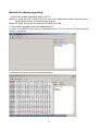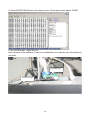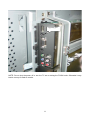
1
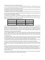
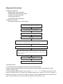
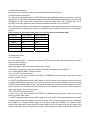
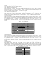
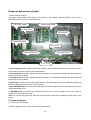
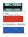
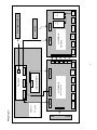
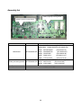
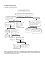
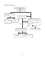
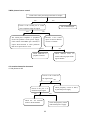
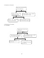
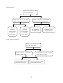
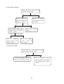
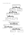
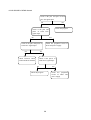
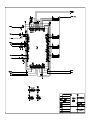
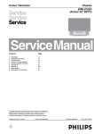
FILE NO.
SERVICE MANUAL
PDP-42XS1
PDP TV
SPECIFICATIONS
Power source: 100-240V, 60/50Hz
Power consumption: 400W
Dimension: 1,246(W) x 731(H) x 305(D)mm
Net Weight: Approx. 41.0kg
Specifications subject to change without notice
REFERENCE No. SM0915001
CONTENTS
Safety Precautions………………………………………………………………………..…1
Alignment instructions. ………………………………….…………………………….…
3
Method of software upgrading …………………………………………….……………………
9
Working principle analysis of the unit……………………..……………………….…………
12
Diagnose and service of panel……………………………………………………………..……
16
Wiring diagram……………………………………………………………………………..…19
Assembly list………..…..…..…..…..…..…..…..…..…..…..…..…..…..…..…..…..…..….20
Trouble shooting guide ………………………………………………………..……………...
21
Schematic diagram …………………………………………………………………….….. 30
Note: This maintenance manual is intended only for the reference of the maintenance people.
Please pay attention to the following points before carrying out the maintenance work.
Safety Precautions
Please read the “Points for attention for the Maintenance & Repair of PDP” and “Criterion for Identifying
the Defects on Screen” as below, before inspecting and adjusting the TV set.
1. “Points for attention for the Maintenance & Repair of PDP”
To avoid possible danger, damage or jeopardy to health and to prevent PDP screen from new damage,
the maintenance people must read the following carefully. If they ignore the following warnings, there will
be deathful risks:
1.1 Screens vary from one model to another and therefore not interchangeable. Be sure to use the same
type of screen in the replacement.
1.2 The operation voltage is approximately 350V for PDP module (including screen, driving circuit, logic
circuit and power module). If you want to conduct maintenance work on PDP module when the set is in
normal operation or just after the power is off, you must take proper measures to avoid electric shock
and never have direct contact or touch with the circuitry of the working module or metal parts. That’s
because within a short time relatively high voltage still remains on the capacitor of the driving part even
after the power is off. Make sure to begin relevant maintenance operation at least one minute after the
power is off.
1.3 Don’t apply on the module any power supply that is higher than the specification. If the power supply
used deviates from the value given in the specification, there might be a possibility of leading to fire or
damage to the module.
1.4 Never have operation or mounting work under unsuitable environment such as areas in the vicinity of
water – bathroom, laundry, water chute of kitchen – sources of fire, heat-radiation parts or direct
exposure to sunlight. Otherwise there will be kickbacks.
1.5 In case foreign substances such as water, liquid, metal slices or others fall into the module carelessly
power must be cut off immediately. Keep the module as it is and do not move anything on the module.
Otherwise it might be possible to contact the high voltage or cause shock short circuit so that it may lead
to fire or electric shock.
1.6 If there is smoke, abnormal smell or sound from the module, please cut the power off immediately.
Likewise in case the screen doesn’t work when the power is on or during the operation, please also cut
off the power at once. No more operation in this case.
1.7 Do not remove or plug its connection wire when the module is in operation or right after the power is
off. That’s because there remains a relatively high voltage on the capacitor of the driving circuit. If there
is a need to remove or plug in the connection wire, please wait at least one minute after the power is off.
1.8 Considering the module has a glass faceplate, please avoid extrusion by external force lest it should
cause glass breakage that may get people injured. Two people are needed in cooperation to move this
module lest contingency takes place.
1.9 The complete TV set is designed on the basis of full consideration of thermal dissipation by
convection, with the round hole on the top for heat emission. To avoid overheat, please do not have any
covering on the hole during normal operation and never put it in the place where the space is narrow and
in bad ventilation.
1.10 There is quite a number of circuits in PDP that are integrated ones. Please be on guard against
static electricity. During maintenance operation be sure to cover yourself with anti-static bag and before
1
operation make sure to have it sufficiently grounded.
1.11 There are a big number of connection wires distributed around the screen. Please take care not to
touch or scuff them during maintenance or removing the screen, because once they are damaged the
screen will fail to work and it’s not possible to repair it.
1.12 Connector for the circuit board of the screen part is relatively fine and delicate. Please take care in
the replacement operation lest it should get damaged.
1.13 Special care must be taken during transportation and handling because strenuous vibration could
lead to screen glass breakage or damage on the driving circuitry. Be sure to use a strong outer case to
pack it up before transportation or handling.
1.14 Please put it for storage in an environment in which the conditions are under control so as to
prevent the temperature and humidity from exceeding the scope stipulated in the specification. For
prolonged storage please cover it with anti-moisture bag and have them piled and stored in one place.
The environmental conditions are tabulated as below:
Temperature
Humidity
Scope for operation
0~50centigrade
Scope for storage
-15~60centigrade
Scope for operation
20%~80%
Scope for storage
20%~80%
1.15 If a fixed picture is displayed for a long time, difference in its brightness and color may occur
compared with movable pictures. But it doesn’t show any problem and the reason is that there is
reduced density of fluorescent powder in the former. On the other hand, even if changes take place in
the picture, it can keep its brightness for a period of time (several minutes). It’s a feature inherent with
plasma and it’s not abnormal. However please try as much as possible to avoid showing a still picture of
high brightness for a long time during operation.
1.16 As a digitalized display devise, this module is provided with error diffusion technology and the gray
scale and false enhancement of contour can be displayed by reusing of sub-field. As compared with
cathode ray tube, it can be found in the moving picture that at the brim of the face of a person there are
some wrong colors.
1.17 During the display of graph (indicating the gradual change in brightness horizontally or vertically)
resulting from gray scale test it can be found that the brightness for the two adjacent levels is uneven.
This is caused by the reuse of sub-field, the display of load rectification and the electrolysis.
1.18 The screen front plate is of glass. Please make sure that the screen has been put in place during
erection. If it is not in place before the erection begins it may lead to screen crack or breakage.
1.19 Make sure the screw used in the mounting of the screen is of the original specs lest it should cause
damage to the screen due to mismatch. Special care should be taken not to use too long or too big
screw.
1.20 Care must be taken to guard against dust during assembling or dismantling, especially to avoid dirt
from falling in between the screen and the glass lest it should harm the receiving and viewing effect.
1.21 There is piece of insulator stuck on the rear chassis corresponding to the power supply board. It is
used to isolate the cool part from the hot part. Please take care to keep it intact lest it should become a
potential safety trouble.
1.22 In addition to plasma screen, the glass is a part of high value. It has such functions as anti-radiation,
adjustment of color temperature etc. Please handle it carefully.
2
Alignment instructions
1 Alignment equipment
PM5518 (video signal generator)
54200 (SCART video signal generator)
VG-849 (VGA signal generator)
CA100 (white balancer)
VG-849 (HDMI signal generator)
2 Alignment flow-chart
The alignment flow-chart is shown as fig-1
Check DDC(N604/N702) and FLASH(N502)
To produce digital board and HF board
Check the digital board and HF board
All testing
Connect with central signal source, then check each function of TV such as
analog control etc., check the output of headphone and speaker
Input AV/S, HDMI and HD signal, then check each function of all the terminals
Input VGA signal (one format), check if the display is normal under PC
condition, check each function such as analog control etc., check horizontal
/vertical center etc.
Preset ex-factory
Check the accessories and pack them in box
Fig-1 adjustment flow-chart
3 Unit adjustments
3.1 Connect jump wire (SW501) to the power +24V for the unit panel.
3.2 After connect the digital board, button board and HF board, check if the display is normal.
3.3 Enter factory menu
The first press the MENU button, then press the “-/--“→ “9” → “1”→ “8” buttons enter factory menu.
Press the SLEEP button to selection the adjustment page menu, press CH+ and CH- buttons to
selection item, press VOL+ and VOL- buttons to set item, press the MENU button exit the factory menu
again. If the unit does not turn off, you press the SLEEP can enter factory menu.
3
3.4 EEPROM initialization
Enter page one of the factory menu, select the EEPROM INITIALIZE to ON.
3.5 White balance adjustment
The eight level gray-scale signal of FLUKE PW5148 video generator sends to AV channel, enter the
factory menu white balance adjustment page. Select the standard color temperature item, fixed the
R GAIN to be 32H, adjust the seventh color coordinate (284, 299) of B, G GIAN; fixed the R
OFFSET to be 32H, adjust the second color coordinate (284,299) of B, G OFFSET.
Note: adjust white balance of standard color temperature of the AV channel, other four channel due
to the software auto adjustment, under the 1200k(270,283), 6500K(313,329) due to the software
pre-set.
Cool and warm color temperature pre-set of the AV channel as follows table:
AV channel
R Offset
G Offset
B Offset
R Gain
G Gain
B Gain
Cool (1200K)
32H
2BH
35H
32H
4AH
3FH
Warm (6500K)
32H
2BH
32H
32H
39H
22H
4 Performance check
4.1 TV function
Enter the search menu → auto search, connect RF-TV terminal to the central signal source, check if
there is station skipping.
4.2 AV/S input terminal
Input AV/S signal, check the picture and sound is normal
4.3 SCART terminal (note: check the SCART terminal, set display mode to AUTO)
4.3.1 Check SCART INPUT special function
4.3.1.1 SCART1 terminal function
a. After turn on the unit, connect the SCART1 to PM54200 signal generator, then the unit auto
select to SCART1 mode.
b. SCART signal generator sends CVBS signal to the unit; check if the image and sound is normal.
It sends image format (16:9 and 4:3) to the unit, check if the unit auto identify is normal. Change
SCART signal to RGB signal; check if the image and sound is normal, It sends image format (16:9
and 4:3) to the unit, check the unit auto identify is normal. Select the PIP mode, connect earphone
cable, and check if the sound is normal.
4.3.1.2 SCART2 terminal function
a. After turn on the unit, connect the SCART2 to PM54200 signal generator, then the unit auto
select to SCART2 AV mode.
b. SCART signal generator sends CVBS signal to the unit, check if the image and sound is normal.
It sends image format (16:9 and 4:3) to the unit, check if the unit auto identify is normal, and display
the SCART2 AV. Change SCART signal to Y/C signal, select the SCART2 Y/C channel mode,
check if the image and sound is normal, It sends image format (16:9 and 4:3) to the unit, check if the
unit auto identify is normal. Select the PIP mode, connect earphone cable, and check if the sound is
4
normal.
4.3.2 Check SCART OUTPUT special function
4.3.2.1 SCART1 terminal function
Input signal in the TV states, connect the SCART1 terminal to the TV. Change the TV program,
check if output signal of SCART1 is TV signal, and the image and sound is normal, change the unit
channel, the CART1 output TV signal, it can not other signal.
4.3.2.2 SCART2 terminal function
Input signal in the TV/AV/S states, connect the SCART2 terminal to the TV. Change the unit
channel, check if output signal of SCART2 is current signal, and the image and sound is normal.
4.4 YPbPr terminal
Input the YUV signal (VG-848 signal generator), separate input YUV format signal of table 1, check
if the image and sound is normal. If the image is deflection of the H-field, select auto sync correction
of the SCREEN menu. If the image is slight disturb, adjust the FINE TUNE correction of the
SCREEN menu. Open the PIP mode, connect the earphone, and check if the image and sound is
normal.
Table 1 YUV format signal
Mode
TIMING parameter
VG848 NO.
480I
712X484@ 60HZ
968
480P
720X484@60HZ
978
576I
702X574@50HZ
969
576P
756X557@50HZ
979
720P @50HZ 1280X720@50HZ
5SET
720P @60HZ 1280X720@60HZ
976
1080I@50HZ 1920X1280@50HZ
1SET
1080I@60HZ 1920X1280@60HZ
972
4.5 VGA terminal
Input the VGA signal (VG-848 signal generator), separate input VGA format signal of table 1, check
if the image and sound is normal. If the image is deflection of the H-field, select auto sync correction
of the SCREEN menu. If the image is slight disturb, adjust the FINE TUNE correction of the
SCREEN menu. Open the PIP mode, connect the earphone, and check if the image and sound is
normal.
4.6 HDMI terminal
HDMI signal format receive the three high definition signal: 480P, 576P, 720P/50/60 Hz,
1080I/50/60 Hz, except for the table 2 signal. Check if the image (contain HDCP ON and OFF) and
sound is normal. If the image is deflection of the H-field, select auto sync correction of the SCREEN
menu. Open the PIP mode, connect the earphone, and check if the image and sound is normal.
TABLE2 VGA signal format
TIMING parameter
VG848 NO.
640X480@60HZ
885
640X480@72HZ
851
640X480@75HZ
852
640X480@85HZ
334(K7253)
720X400@70HZ
855
5
720X400@85HZ
960
800X600@56HZ
853
800X600@60HZ
854
800X600@72HZ
887
800X600@75HZ
945
1024X768@60HZ
856
1024X768@70HZ
857
1024X768@75HZ
858
1280X1024@60HZ
963
4.7 Ex-factory setting see to TABLE 3 - TABLE 7
TABLE 3 Factory Option Menu
ITEMS
EX-FACTORY SETTING
IIC Bus-off
EEPROM Erase
Backlight Adjustable
Back Light
Menu Timeout
Blank switch enable
Off
Off
Off
100
10
Off
ShowLogo
On
Auto Channel Lable
On
West Europe / East Europe / Cyrillic /
Turkish /Greek/Arabic/Hebrew
Dynamic Scart
Off
Note: the latter 6 items should set according to clients’ require.
TT Char Group
TABLE 4
ITEMS
Volume 1
Volume 25
Volume 50
Volume 75
Volume 100
ITEMS
Volume 1
Volume 25
Volume 50
Volume 75
Volume 100
MSP Scart1 Volume
ITEMS
Prescale Scart
Factory Audio Setting
EX-FACTORY SETTING
45H
62H
67H
6EH
76H
HP VOLUMESETTING
EX-FACTORY SETTING
64H
96H
A1H
AEH
BEH
72H
EX-FACTORY SETTING
4CH
6
Prescale FM/AM
Prescale Nicam
30H
64H
Scart TV Volume
Scart AV Volume
D/K select HDEV3
AVC
Equalizer Bands Max
Spatial Mode
Spatial Strength
20H
72H
Off
Off
60H
0
00H
ITEMS
Bright Min
Bright Middle
Bright Max
CVBS
D5H
00H
15H
TABLE 5 Factory Video limit Setting
SC-RGB
YPBPR
D-SUB
DFH
C6H
D5H
D8H
02H
01H
07H
09H
20H
18H
2BH
18H
Contrast Min
Contrast
Middle
Contrast Max
09H
20H
0CH
20H
16H
26H
10H
32H
0CH
2AH
2DH
3EH
3FH
29H
Sharpness
Min
Sharpness
Middle
Sharpness
Max
00H
00H
00H
00H
10H
10H
10H
10H
1FH
1FH
1FH
1FH
Color Min
Color Middle
Color Max
00H
3FH
50H
00H
3FH
7FH
00H
3FH
7FH
00H
3FH
7FH
00H
32H
63H
Hue Min
Hue Middle
Hue Max
CEH
00H
32H
CEH
00H
32H
CEH
00H
32H
CEH
00H
32H
CEH
00H
32H
TABLE 6
Vivid
Contrast
Brightness
Color
Hue
80
60
60
00
1FH
00H
10H
1FH
THE IMAGE ANALOG SETTING
Standard
Mild
75
50
50
50
50
40
00
00
7
HDMI
Custom
75
50
50
00
Sharpness
50
50
50
50
Note: in factory menu states, it can change the factory mode to value of the image and
sound, else select the image and sound balanced value in the other states.
120Hz
500Hz
1.5KHz
5KHz
10KHz
TABLE 7 SOUND equilibrium value setting
Live
Pop
Rock
50
50
65
50
50
55
50
60
55
80
70
55
85
70
55
Custom
50
50
50
50
50
4.8 Ex-factory setting of user menu
4.8.1 select TV channel
4.8.2 video menu, Mode: Standard, NR: Medium, APL:ON
4.8.3 sound menu, Volume: 20, Balance: 00, Equalizer: Custom, HP Volume: 20;
4.8.4 edit menu, Color System: Auto, Sound System: DK;
4.8.5 option menu, Default Zoom: Auto, Child Lock: Off, Menu Language: English, Country: UK,
WSS: OFF, Blue Screen: On.
Note: the 4.8.4 and 4.8.5 items should set according to clients require.
8
Method of software upgrading
1. Enter the software upgrading state of the TV
Method 1: press the VOL- button in the unit, turn on the main power switch, then the screen
display black screen, but the indicator to blue.
Method 2: Enter factory menu, select the IIC-BUS OFF item.
2. Connection upgrading tools with upgrading port.
3. Dual- click IAPWriter logo, enter the upgrading states (if the PC and the IIC communication
trouble, it can prompt.
4. Select the file menu load the software follow as:
9
5. Select WRITE DEVICE item of the device menu, till the right screen display “DONE”.
6. turn off the power , restart the unit.
Note: because of the software, it may be no-stabilization, the software can auto download
and write.
Upgrading tools
Connection cable
10
Upgrading port
NOTE: Do not shut the power off or turn the TV set on during the FLASH write. Otherwise it may
lead to no way for flash to rewrite.
11
1. Block diagram
Working principle analysis of the unit
12
Including:
CPU: RENESAS M16C (M30620SPGP)
Video decoder: SVP-EX62 / sub-screen TVP5147
AD conversion/line by line conversion /Teletext decodes: SVP-EX62
HDMI: SILICON IMAGE the second generation processing CMOS chip SiI9011
Audio processing: MSP3410
Sound power amplifier: D class audio MP7720 (single channel)
The CPU of the unit is M16C (N501) which mainly control the working of all CMOS chips, including
(receiving infrared telecontrol / keystoke, standby control, I/O control); the main CMOS chips is
SVP-EX62 (N201) which mainly in charge of function of the picture dispose, passage conversion,
picture display, menu display, picture effect adjust, accompany sound dispose (including volume
adjust, the control of high and low volume, stereo decode), the control of channel search,
TELETEXT decode.
2.sound parts:
The unit adopt double tuner (including tuner and IF amplifier circuit), antenna receives signals
sends the signals to the TUNER1, TUNER1 contains high frequency distributor, the RF signals
distribute one way to the TUNER2, thereinto the fourteen foot of TUNER1 supply the power (+5V)
for the high frequency distribution part. Tuner under the control of assistant CPU (N502) (SDA,
SCL) to choose the appropriate channel and then switch to the right TV system, output video
signals and audio signals after HF amplifier and IF amplifier decoding. The output signals of
TUNER1 sent to decoder SVP-EX62 as the main screen display, while TUNER2 sent to decoder
TVP5147 (N801) as the display of sub-screen.
Audio signals sent to audio processing MSP3410 (N101) directly, meanwhile double tuners will
send the SIF to N101 dispose (use to stereo decode and automatic volume control). N101 is
provided with audio channel switch, the audio input of mainboard (VGA/HDMI/YprPb signal) is sent
to N101 with TV and AV after via N707 chip switching. The audio signal: one-way via volume and
high-low sound control after, them left and right sound sent to sound power amplifier MP7720 and
then send to speaker. Other way left and right sound sent to earphone power amplifier JRC1109
(N104) after, them sent to earphone. The volume is controlled the controller signal (SDA and SCL),
other way sound of AV out the output SCART terminal of video board.
Audio processing IC
The diagram of MSP3410 shown as follows:
13
Descriptions of the pins:
2, 3: SCL, SDA, control the IC working
27, 28: Output to the right and left sound channel of sound power amplifier
33, 34: the right and left sound channel of earphone
36, 37: the right and left sound channel of AV OUT sound
47, 48: the left and right sound channel from main board
50, 51: the left and right sound channel of AV IN sound channel
53, 54: the left and right tracks of the TV sub- channel
56, 57: the left and right tracks of the TV main- channel
67, 69: the SIF input of the TV main- channel and sub- channel
The MP7720 is a sound high effect of the D class amplifier, it output 10W in the without cooling fin.
3 picture parts:
AV/SV and SCART AV/YC via switch change N708 after, them sent to SVP-EX62 decode, then two
way AV/SV and PIP TV to TVP5147 decode, but this unit only PIP TV decode.
TVP5147 chip is single chip video decoder, it include internal Y/C separate, 2D five line filter,
MICROVISION IIC communicate and HS and VS output, the supply power supply +1.8V and +3.3V
voltage to it.
3.1 The diagram of TVP5147 shown as follows:
14
Thereinto:
Pin16 is the PIP TV signal input
Pin8 foot is AV or Y (SV) input
Pin1 is C (SV) signal input
Pin7 is SCART CVBS or Y signal input
Pin80 is SCART C signal input
3.2 SVP-EX62 diagram shown as follows:
15
Diagnose and service of panel
1. Block function of panel
The power supply board, Logic board, X drive board, Y drive board, Logic BUFFER (E and F) and Y
BUFFER (upper and lower) of the PDP panel.
Y BUFFER (upper)
Power supply board
Y drive board
X drive board
Y BUFFER (lower)
Logic board
Logic BUFFER (E)
Logic BUFFER (F)
COF(7 piece)
* Power supply board: to supply power for the screen, other functional modules on the screen, our own
main board, and video frequency processing board.
* X driving board: to produce and provide driving signal for X electrode according to the time sequence
signal sent from logic board.
* Y driving board: to produce and provide driving signal for Y electrode according to the time sequence
signal sent from logic board.
*Logic board: to process the image signal sent from the main board, to produce addressing signal and
to provide driving signal for X and Y driving boards.
*Logic BUFFER board: To convert the data signal and control signal sent from the logic board into the
signals required by COF.
*Y BUFFER board: to transmit the scanning signal from the Y driving board to the screen, which is
divided into upper and lower parts.
*COF: to convert the signal sent from the logic BUFFER board into the address signal used by the
screen.
2.Trouble diagnosis:
2.1 The screen is not bright:
2.2 There appears on the screen a line or several unlit lines.
16
Check if the socket between Y driving board and Y BUFFER is plugged well. If not, plug it well. If yes
then replace Y BUFFER (upper, lower) in respect to the upper, lower part of the dark line on the screen.
2.3 There appear on the screen one or several horizontal lines that are much brighter than the remaining
horizontal lines at the edge:
Check if the socket between Y driving board and Y BUFFER is plugged well. If not, plug it well. If yes
then replace Y BUFFER (upper, lower) in respect to the upper, lower part of the dark line on the screen.
4.There appear on the screen one vertical unlit line or a vertical entirely unlit block
a. If it’s one vertical unlit line, then COF has problem.
b. If it’s a vertical entirely unlit block, then first check if the connection socket between COF and logic
BUFFER has problem. If not, check if the connection sockets between the logic BUFFER and the logic
board is normal. If yes, replace the logic BUFFER. Finally, if the problem still remains when the
replacement is over, then replace the logic board.
5.There appears on the screen a mono color signal and one or several vertical bright lines of other
colors:
a. If it’s a vertical bright line of other colors, then the problem lies with COF or the screen.
b. If it’s an entire vertical block of other colors, then first check to see if the connection socket between
17
COF and logic BUFFER has problem. If no problem, check if the connection sockets between the logic
BUFFER and the logic board is normal. If it’s normal, then replace the logic BUFFER. If the problem still
remains after the replacement, then replace the logic board. Finally if the problem is still there, then the
problem lies with COF.
6.There appear on the screen abnormal bright spots or blocks that are different from what’s described
above:
a. Check if the connection socket between COF and logic BUFFER board has been well plugged.
b. Replace the logic BUFFER board. If it’s not solved then replace logic board. If the problem still
remains, then it’s the problem with COF.
18
7
X902(7PIN)
Earphone
X711
LG screen
PDP42V7
Wiring Diagram
board
Button
9
667-PS42W6-69
Audio L/R
Data processing board
YPbPr
P1
CN804
VGA
CN802
CN01
input
Earphone
X301(31PIN)
Logic circuit board
X901(9PIN)
CN801
Power supply
31
19
HDMI
X903
X703
X712
X709
X710
4
10
12
4
6
X109
X103
X101
X102
X104
SCART
SCART
Video board
Earphone
output
667-PS42W6-40
S-VIDEO
X111
X110
VIDEO
Sub
TUNER
4
speaker
RF
Main
TUNER
Power supply switch assy
4
2
Assembly list
Analog signal processing board
Digital signal processing board
Name
Main board
Video processing board
NO.
Main IC and NO.
667-PS42W6-69
N201 SVP-EX62
(353-DPTV0-60)
N302/N302 DS90C385MTD (353-03850-20)
N401 K4D2632838F
(353-26323-10)
N501 M30620SPGP
(353-30620-20)
N502 W29C040P
(353-29040-30)
N607 SII9011CLU
(353-90110-10)
N801 TVP5147PFP
(353-51470-10)
667-PS42W6-40
N102/103 MPS7720DS (353-77200-10))
N101 MSP3410G
(353-34100-80)
N104 NJW1109M
(353-11090-20)
Remote control
301-IL27W18-02(X)
Button board
667-PS42W6-05
20
Trouble shooting guide
1.No raster, no picture, no sound
No raster, no picture, no sound.
Check if the power supply indicator light is on.
After turn on the unit, check
if the blue is normal.
Abnormal
N502 is
Abnormal
Red indicator is off
Check 5V-STBY
Normal
Check if the blue and red
indicator is normal.
There are on
Red indicator is on
There are off
Check the union
joint of the power
supply board to
LVDS line.
Abnormal
Check power
supply board
Check if the pin2 of
X902 is high level.
Abnormal
Cut off the connection
between power supply board
and digital signal processing
board, and test 5V-STBY
Normal
Check the digital signal
processing and analog
signal processing board
Normal
N502 is
Abnormal
Check
N501
Check if the pin6
of X902 is +5V.
Normal
Check if N501
and +5V-PANEL
is short circuit.
Abnormal
Check the power
supply board
NOTICE: The PDP power supply have the protection function of overcurrent, overvoltage and so
on, if certain route power supply appear overcurrent and overvoltage, the power supply should
appear the protection to arise no-output.
21
2.With sound but no picture:
With sound but no picture.
Display logo?
Yes
No
Check if all other channel
has no picture.
No
Check
N201
and periphery
circuit
Check if the X301
have the signal wave.
Yes
Turn to check 4
of program
Normal
Abnormal
Unfix X901, X902 and X301, set
SW501 of the power supply board
as AUTO, use to itself source
signal, and check if turn on the
unit is normal
Normal
Check the input signal of N301
and N302 and power supply.
Normal
Abnormal
N301 and N302
damaged.
Check N201 and the circuit
of output.
22
Abnormal
The screen damaged.
3.With picture but no sound:
Check if the video processing board X110 is output.
No
Yes
Check if the second pin of sound
power amplifier input the signal.
Yes
The sound damaged.
No
Measure if the sound
input of current channel
of N101 is normal.
The sound power amplifier or peripheral
circuit has problem. Check power supply,
if the control of ENABLE pin is normal; if
output short-circuited or other problems
that causes protection to work.
Yes
No
Check MSP3440 or
peripheral circuits.
Check different levels of
circuit following input audio
signal channel.
4. A certain channel is abnormal
4.1 No picture on AV
Check if the C228 has
the signal input.
Yes
No
Check periphery circuit of N201,
crystal and power supply
Check if the pin 2 of
N708 has input signal.
Yes
No
Check the AV terminal
socket to N708 channel
Check the periphery circuit
of N708 and power supply
23
4.2 no picture on S-terminal
Check if the C228 and C229
have the signal input.
No
Yes
Check if the pin 2 of
N708 has input signal.
Check periphery circuit of N201,
crystal and power supply
Yes
No
Check the periphery circuit
of N708 and power supply
Check
the S-terminal
socket to N708 channel
4.3 NO picture of TV channel
4.3.1 mainframe
Check if the C227 have the
signal input.
No
Yes
Check if the pin 2 of TUNER101
in TV board has input signal.
No
Check the TUNER101 to
N708 circuit.
Check periphery circuit of N201,
crystal and power supply
Yes
Check the periphery circuit
of TUNER101 and power
supply bus wire
24
4.3.2 sub frame
Check if the pin16 of N801
have the signal input.
Yes
No
Check if H and V sync clock
signal of N801 output is normal.
Yes
Check if the pin12 of TUNER102
in TV board has the signal output.
No
Check the
peripheral
circuit of N201,
crystal and
power supply.
Yes
No
Check between
the TUNER102
and N801 circuit
Check the
peripheral
circuit of N801,
crystal and
power supply.
Check the peripheral
TUNER102, power
supply and BUS
4.4 No picture of SCART2
Check if the C228 and C229
have the signal input.
No
Yes
Check if the pin 3 and pin6 of
N708 has input signal.
Yes
Check peripheral circuit of
N708 and power supply
Check periphery circuit of N201,
crystal and power supply
No
Check between the SCART2
socket and N708 circuit
25
4.5 No picture of SCART1
Check if the C223, C224, C225 and
C226 have the signal input
Yes
No
Check if between the
pin16 of SCART1 socket
and N501 is normal.
No
Yes
Switch RGB and VIDEO input
SCART1, check if the PIN87
of N501 is normal
Yes
Between the SCART1
socket and N201 channel
has problem
Check the
channel
connector
No
Check the peripheral
circuit of N201, crystal
and power supply
Check the peripheral
circuit of N501 and
power supply
4.6 no picture of HDMI
Check if the H-V syncs signal and clock
signal of N607 output is normal
Yes
No
Check the peripheral circuit of
N201, crystal and power supply
Check the peripheral circuit of
N201, crystal and power supply;
check if HDMI socket connector
is normal
26
4.7 No picture of YPBPR or YCBCR
Check if the C220, C221 and C222
have the signal input
No
Yes
Check if the pin4, pin7
and pin9 of N706 have
signal input
No
Check the peripheral
circuit of N201, crystal
and power supply
Yes
Check between N706
and N201 channel
Check if the pin2, pin5 and
pin11 of N706 have signal
input
No
Yes
Between the YPBPR
socket and N706 channel
has problem
Check the peripheral
circuit of N706 and
power supply
4.8 No of picture of D-SUB channel
Check if the YPBPR signal display is normal
NO
YES
Check if the T4 and U1 of N201 have sync
signal input
YES
Check N201
Check the program
NO
Check if the PIN1 and PIN5 of N201 have sync signal input
YES
Check the peripheral
circuit of N709 and
power supply
27
NO
Between the VGA socket
and N709 channel has
problem
4.9 NO SOUND of HDMI channel
Check if the pin1 and pin3 of N707
have the signal input
No
Yes
Check the program
Check if the pin1 and
pin12 of N707 have
signal input
No
Yes
Check the peripheral circuit of
N707 and power supply
Check if the pin7 and pin10 of
N707 have signal input
No
Yes
Check between N601
socket and N707 channel
Check if the pin1-4 of
N601 have signal input
No
Yes
Check the program
Check the peripheral
circuit of N601 and
power supply
28
4.10 Abnormal of the picture:
4.10.1 color abnormal
a. A certain differential wire pair of LVDS (RX0+/-, RX1+/-, RX2+/-, RX3+/-) of X301 is abnormal, which
may lead to lack of color (it’s not a complete loss of color).
b. Failure with resistor rows R225~R2300, which may lead to loss of corresponding color from the gray
degree corresponding to the picture of all channels.
c. Failure with resistor rows R819~R822, which may lead to loss of corresponding color from the gray
degree corresponding to the picture of VGA/YPRPB/AV/TV channels.
d. Failure with resistor rows R653~R659, which may lead to loss of corresponding color from the gray
degree corresponding to the picture of HDMI channel.
4.10.2 Abnormal picture vertically or horizontally (bar like): Abnormal in complete line extending all the
way from up downward on the screen of stand definition TV set; abnormal vertically on half screen of
high definition TV set. They may be caused by the damage of the address BUFFER module that directly
corresponds to its position, or may be caused by the damage of the connection wire that directly
corresponds to the position of the screen. The horizontal bar like abnormality is also related to the Y
driving circuit that corresponds directly to its position. To judge these phenomena, It’s possible to check it
by setting the screen to the status of self check as explained above
4.10.3 No brightness in the square block area: Normally it’s caused by the damage of the address
BUFFER module that directly corresponds to its position, or may be caused by the damage of the
connection wire that directly corresponds to the position of the screen. To judge these phenomena, It’s
possible to check it by setting the screen to the state of self check as explained above.
29
RC
DIGITAL
PROCESSING ASS'Y
SOUND
PROCESSING ASS'Y
POWER ASS'Y
TV BOARD ASS'Y
FRONT CABINET
BACK CABINET
USER MANUAL
Model NO.
PDP-42XS1
203-PS42W60-13
XIIL27W1802F
XI667PS42W669
XI667PS42W640
XI780I06R07A0
XI611I08RQAF3A
XIPS42W6S300
603-PS42W6S-00
Ver.1.0