1
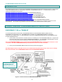
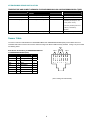
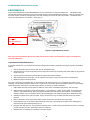
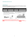
ENVIROMUX® Series
Sensor Installation Manual
ENVIROMUX-T / RH/ TRH(M)-E7
Temperature/Humidity sensors
ENVIROMUX- LDSx-y
Liquid Detection Sensor
ENVIROMUX-SRN-M
Siren
ENVIROMUX-BCN-R
Beacon
ENVIROMUX-TDS
ENVIROMUX-M-DCS
Tamper Switch
Door Contact Switch
MAN057
Rev Date 10/15/2015
NTI ENVIROMUX SENSOR INSTALLATION
TABLE OF CONTENTS
Introduction...................................................................................................................................................................... 2
Connect Sensors to ENVIROMUX-MINI-LXO................................................................................................................. 2
ENVIROMUX-T, RH, or TRH(M)-E7............................................................................................................................ 2
ENVIROMUX-LD ......................................................................................................................................................... 4
Contact Sensors .......................................................................................................................................................... 4
Connect Sensors to The ENVIROMUX-xD Models ........................................................................................................ 6
RJ45 Sensors .............................................................................................................................................................. 6
Temperature, Humidity, Noise Level and Light Sensors .......................................................................................... 6
Contact Sensors ....................................................................................................................................................... 7
Digital In Terminals................................................................................................................................................ 7
Liquid Detection Sensors.......................................................................................................................................... 9
BEACON and SIREN Connections ........................................................................................................................... 10
RJ45 Sensor Cable.................................................................................................................................................... 11
TABLE OF FIGURES
Figure 1- Connect sensors to ENVIROMUX-MINI-LXO ..................................................................................................................... 2
Figure 2- Liquid detection sensor....................................................................................................................................................... 4
Figure 3- Terminal block for dry-contact sensors............................................................................................................................... 5
Figure 4- Sensors connected by cables with RJ45 connectors.......................................................................................................... 6
Figure 5- A portion of the sensor configuration page ......................................................................................................................... 6
Figure 8- Contact sensor wired to RJ45 socket ................................................................................................................................. 7
Figure 9- “DIGITAL IN” terminal blocks on ENVIROMUX Systems ................................................................................................... 7
Figure 10- Basic DIGITAL IN Terminal Connections ......................................................................................................................... 8
Figure 11- Secure liquid detection sensor with tape .......................................................................................................................... 9
Figure 12- Portion of Water Sensor configuration page ..................................................................................................................... 9
Figure 13- Connect visual and audible external indicators............................................................................................................... 10
1
NTI ENVIROMUX SENSOR INSTALLATION
INTRODUCTION
Many different sensors can be connected to the ENVIROMUX Series Enterprise Environment Monitoring Systems. Series models
include ENVIROMUX-SEMS-16U, ENVIROMUX-16D/5D/2D, and ENVIROMUX-MINI-LXO. A complete listing of available
sensors and accessories can be found at
http://www.networktechinc.com/enviro-rems.html for the ENVIROMUX-SEMS-16U,
http://www.networktechinc.com/environment-monitor-16d.html for the ENVIROMUX-16D,
http://www.networktechinc.com/environment-monitor-5d.html for the ENVIROMUX-5D,
http://www.networktechinc.com/environment-monitor-2d.html for the ENVIROMUX-2D, and
http://www.networktechinc.com/environment-monitoring.html for the ENVIROMUX-MINI-LXO.
http://www.networktechinc.com/environment-monitor-micro.html for the ENVIROMUX-MICRO-T(RHP)
Manuals for each Environment Monitoring System covering installation and configuration for all features can also be found at
these websites. This manual is only provided to instruct how to connect the various sensors to these systems.
CONNECT SENSORS TO ENVIROMUX-MINI-LXO /-MICRO-T(RHP)
ENVIROMUX-T, RH, or TRH(M)-E7
For measuring temperature and humidity, the ENVIROMUX-MINI-LXO and ENVIROMUX-MICRO-T(RHP) uses the
ENVIROMUX-T-E7 (temperature only), ENVIROMUX-RH-E7 (humidity only), ENVIROMUX-TRH(M)-E7 (combination
temperature and humidity sensor). For high-temperature environments, ENVIROMUX-MINI-IND uses the ENVIROMUX-T-INDE7 High Temperature Sensor.
1. Connect either of the temperature / humidity sensors to an available port on the ENVIROMUX-MINI-LXO. Plug the RJ45
connector to either of the two ports marked "TEMPERATURE/HUMIDITY". The ENVIROMUX-T/RH/TRH(M)-E7 sensors
can be secured anywhere that the temperature and/or relative humidity need to be sensed.
Note: The ENVIROMUX-TRHM-E7 sensor will work with the ENVIROMUX-MINI-LXO provided firmware version 2.3 or later
is installed, and with the ENVIROMUX-MICRO provided firmware version 1.3 or later is installed.
2.
Power-cycle the ENVIROMUX-MINI-LXO after the sensor(s) have been plugged-in.
Note: Mounting the sensor in the path of a fan or on a heated surface may affect the accuracy of the sensor’s readings.
Note: For best results, use the ENVIROMUX-T-IND-E7 with model ENVIROMUX-MINI-IND.
To extend a sensor cable (up
to 500 feet long) requires
ENVIROMUX-MINI-LXO
firmware version 2.0 or later.
Figure 1- Connect sensors to ENVIROMUX-MINI-LXO
2
NTI ENVIROMUX SENSOR INSTALLATION
TEMPERATURE AND HUMIDITY SENSORS FOR ENVIROMUX-MINI-LXO AND ENVIROMUX-MICRO-T(RHP)
SENSOR MODEL
OPERATING TEMPERATURE
RANGE
HUMIDITY RANGE
ACCURACY
ENVIROMUX-T-E7
32 to 104°F (0 to 40°C)
n/a
±1.35°F (±0.75°C).
ENVIROMUX-RH-E7
n/a
20 to 80% RH.
±5% RH
ENVIROMUX-TRH(M)-E7
-4 to 185°F (-20 to 85°C)
0 to 90% RH.
• ±0.90°F (±0.50°C) for -4 to
14°F (-20 to -10°C).
• ±0.72°F (±0.40°C) for 14 to
185°F (-10 to 85°C).
±5% RH
ENVIROMUX-T-IND-E7
32 to 167°F (0 and 75°C)
n/a
±2.25°F (±1.25°C)
Sensor Cable
The CAT5 connection cable between the ENVIROMUX-MINI-LXO / ENVIROMUX-MICRO-T(RHP) and the RJ45 Sensors is
terminated with RJ45 connectors and must be wired according to the EIA/TIA 568 B industry standard. Wiring is as per the table
and drawing below.
Pair 3
RJ45 Sensor Socket Wiring for ENVIROMUX-MINI-LXO
Pair 2
Pair 1
Pair 4
and ENVIROMUX-MICRO-T(RHP):
Signal
Pin
+5 VDC
1
Wire Color
White/Orange
Pair
2
TRIG
2
Orange
2
SCL
3
White/Green
3
GND
4
Blue
1
SDA
5
White/Blue
1
GND
6
Green
3
FREQ
7
White/Brown
4
ID
8
Brown
4
T R T R T R T R
1 2 3 4 5 6 7 8
+ - + - + - + -
(View Looking into RJ45 Socket)
3
NTI ENVIROMUX SENSOR INSTALLATION
ENVIROMUX-LD
Connect the liquid detection sensor ENVIROMUX-LD to a set of terminals (1-5) marked “DIGITAL IN”. The twisted orange
sensing cable should be placed flat on the surface (usually the floor) where liquid detection is desired. If tape is required to hold
the sensor in place, be sure to only apply tape to the ends, exposing as much of the sensor as possible. At least 5/8" of the
sensor must be exposed for it to function. (See Figure 2)
Do not expose connector
to liquids.
Do not submerge.
Figure 2- Liquid detection sensor
Note: The connection between the two-wire cable and the sensor cable is not designed for exposure to liquids and
cannot be submerged.
Liquid Detection Rope Maintenance
For periodic maintenance, you can clean the rope with isopropyl alcohol without completely removing the rope from its installed
location.
1.
Remove the section that you want to clean from its self-adhesive clips.
2.
Soak the alcohol in a dye-free rag and proceed to wipe it around the rope, squeezing firmly while pulling the rag down the
length of the rope.
3.
Flip the rag every several feet and re-saturate the rag with alcohol when needed.
4.
After cleaning a section of the rope, you can replace it and continue to clean the next section in similar fashion.
5.
Replace the rag if it becomes too dirty.
If the rope is still giving you problems after you have cleaned it with isopropyl alcohol or if you think the rope needs a good
scrubbing, you can clean it with warm soapy water. You will have to remove the rope from its installed location. It may be helpful
to label the sections of the rope or note their locations before you start for an easier re-installation.
1.
Gather Dawn dish soap, a large bucket or plastic bin, warm water, soft-bristled scrub brushes, and clean rags.
2.
Add dish soap to the bucket of water, approximately 1 cup of detergent to 1 gallon of warm water. To determine if the
solution is concentrated enough, place your finger and thumb in the water and rub them together. You should feel a
slick/slimy residue. If you do not feel a residue, add more detergent to the water and gently mix to distribute the soap.
3.
Submerge a section of the rope in the water. Using a scrub brush or rag, scrub along all sides of the rope with firm
pressure.
4.
Remove the section of the rope from the soapy solution and rinse it in a bucket of clean, fresh water.
5.
Ensure that there are no oily deposits along the length of the rope. If the rope does not appear clean, submerge it in
water and scrub again, repeating steps (3) to (5).
6.
Hang the clean rope up to dry. Try to point the connectors down, so water cannot pool inside the connectors. The drying
process may take 6-8 hours, depending on the room conditions.
7.
When the rope is completely dry, reinstall it in its original location.
4
NTI ENVIROMUX SENSOR INSTALLATION
Contact Sensors
Up to five dry-contact sensors or liquid detection sensors can be connected to the terminals marked “DIGITAL IN”. Sensors with
16-26 AWG connection wires that operate on 5V at 10mA maximum current may be used. A contact resistance of 10kΩ or less
will be interpreted by the ENVIROMUX-MINI-LXO as a closed contact.
Examples of Dry-Contact Sensors for the ENVIROMUX-MINI-LXO:
NTI #
Description
NTI #
Description
ENVIROMUX-EBS
Emergency Button
ENVIROMUX-SDS-PA
Smoke Detection Sensor-Power added
ENVIROMUX-IMD-P
Infrared Motion Sensor w/power
ENVIROMUX-TDS
Tamper Switch
ENVIROMUX-M-DCS
Door Contact Sensor
To install the dry-contact sensor(s):
A. Attach the positive lead to a terminal corresponding to a "+" marking on the ENVIROMUX-MINI-LXO and the ground lead
to the next terminal to the right that will correspond to a “
“ marking on the ENVIROMUX-MINI-LXO. Tighten the set
screw above each contact. Terminal sets are numbered 1-5.
B. Mount the sensors as desired.
Figure 3- Terminal block for dry-contact sensors
Note: The terminal block is removable for easy sensor wire attachment if needed.
Shielded cable must be used to connect to the DIGITAL IN terminals in order to meet CE emission requirements.
Connect the drain wire of the shield to the ground (
) terminal of the dry contact in addition to the contact return wire.
5
NTI ENVIROMUX SENSOR INSTALLATION
CONNECT SENSORS TO THE ENVIROMUX-XD MODELS
RJ45 Sensors
Several sensors for the ENVIROMUX-16D/5D/2D and ENVIROMUX-SEMS-16(U) Enterprise Environment Monitoring Systems
have RJ45 connection ports. Some of these sensors include ENVIROMUX-STS (temperature only), ENVIROMUX-SHS (humidity
only), ENVIROMUX-STHS (temperature and humidity), ENVIROMUX-STHS-99 (wide range temperature and humidity),
ENVIROMUX-LDS (liquid detection) and ENVIROMUX-LS (light detection). In all cases, the CAT5 cable between the sensor and
the ENVIROMUX can be up to 1000 feet in length.
Temperature, Humidity, Noise Level and Light Sensors
Note: It is very important to locate the temperature
and/or humidity sensors away from ventilation sources
and fans.
Connect each sensor to one of the female connectors
labeled "RJ45 Sensors" on the ENVIROMUX. Male
connectors should snap into place. See page 7 for wiring
specification and pinout.
Note: Shielded CAT5 cable
is required between the
sensor and the ENVIROMUX
to maintain CE compliance
of the sensor.
Figure 4- Sensors connected by cables with RJ45 connectors
Application Note:
When connecting temperature and humidity sensors to the ENVIROMUX, the web interface will identify the sensor accordingly for
the type of sensor it is. The status bar and configuration page will enter the maximum and minimum range that this type of
sensor can operate at if used with the ENVIROMUX, not necessarily the operating range of the sensor itself. The various
temperature and humidity sensor models offered by NTI have varying ranges of performance capabilities, as indicated in the table
on the next page. Be sure to match the sensor installed to the operating range of the environment it will be expected to work in.
Using a sensor outside of its intended temperature range may result in damage to the sensor.
This is the range the ENVIROMUX will
display, not necessarily the range the
sensor will work within. See
specifications for the sensor being
installed for the proper operating
environment.
Figure 5- A portion of the sensor configuration page
6
NTI ENVIROMUX SENSOR INSTALLATION
Contact Sensors
Some sensors do not have RJ45 connectors on them and instead have terminal blocks. These can either be connected to the
"DIGITAL IN" connectors or they can be terminated and plugged into the remaining RJ45 connectors (see Figure 6). (The
illustration uses CAT5 patch cable to make cable connection easy.) Examples of these sensors include ENVIROMUX-IMD
(motion detector), ENVIROMUX-IMD-CM (ceiling mount
motion detector), ENVIROMUX-VSS (vibration sensor),
ENVIROMUX-SDS (smoke detection), and ENVIROMUXGBS (glass break sensor).
Note: For sensors requiring 5VDC power source,
substitute the wire connected to pin 4 (see below)
instead of pin 7.
When applying CAT5 cables to contact sensors for plug-in
to the RJ45 Sensor sockets, the following socket-tosensor wiring must be followed:
RJ45 Sensor Socket Pinout
Pin #
Pin Name
1
GND
2
SENSE
3
RS485 +
4
+5 VDC
5
TAMPER SWITCH
6
RS485 -
7
+12 VDC
8
GND
Figure 6- Contact sensor wired to RJ45 socket
Digital In Terminals
To connect contact sensors without using RJ45 connectors, terminal blocks have been provided labeled "DIGITAL IN". Two wire
switch-only type sensors can be connected to the plus (+) and minus (-) terminals (ENVIROMUX-16D) or the plus (+) and ground
( ) terminals (ENVIROMUX-2D/5D). If the sensors require a 12V power source to operate, these models include 12V and
ground terminals for a power connection. Connect each two-wire or four-wire contact sensor using 16-26 AWG wire.
Figure 7- “DIGITAL IN” terminal blocks on ENVIROMUX Systems
FYI: The terminal block is removable for easy sensor wire attachment if needed.
7
NTI ENVIROMUX SENSOR INSTALLATION
Figure 8- Basic DIGITAL IN Terminal Connections
8
NTI ENVIROMUX SENSOR INSTALLATION
Liquid Detection Sensors
Liquid Detection Sensors are available for simple connection to either the “Digital In” terminals (use model ENVIROMUX-LD or
ENVIROMUX-LD-LC) or the “RJ45 Sensor” ports (use model ENVIROMUX-LDS).
Connect the two-wire cable (up to 1000 feet long) from a liquid detection sensor (ENVIROMUX-LD shown in Figure 2-upper
image) to a set of “DIGITAL IN” contacts. For added range (up to 1000 more feet), use an ENVIROMUX-LDS (shown in Figure
2-lower image) and connect to an “RJ45 Sensor” port.
The twisted orange sensing cable should be placed flat on the surface (usually the floor) where liquid detection is desired. If tape
is required to hold the sensor in place, be sure to only apply tape to the ends, exposing as much of the sensor as possible. At
least 5/8" of the sensor must be exposed for it to function. (See Figure 2)
NOTE: When installing the
ENVIROMUX-LD-LC, it is very important
to assure the sensing cable does not
cross over itself or cross conductive
surfaces to avoid false triggers.
Figure 9- Secure liquid detection sensor with tape
To test the ENVIROMUX-LD(S);
1. Configure the sensor. (Normal Status set to “Open”, Sampling Period set to 5 seconds.)
2. Submerge at least ½ inch of the exposed twisted orange wire (not the wrapped end) for up to 30 seconds. Do NOT use
distilled water as water must be conductive.
3. Monitor the sensor to see the sensor “Value” change from “Open” (dry) to “Closed” (wet).
4. Dry the exposed area of sensor and the sensor “Value” should change back to “Open” within 30 seconds.
Figure 10- Portion of Water Sensor configuration page
9
NTI ENVIROMUX SENSOR INSTALLATION
BEACON and SIREN Connections
Terminals have been provided for connection of a beacon (ENVIROMUX-BCN-R(L)) and siren (ENVIROMUX-SRN-M,
ENVIROMUX-BEEP1, etc) to use for visual alerts and audible alerts when configured. Devices such as this can be installed
in locations best suited to get attention. All devices must be installed using 16-26 AWG wire.
Figure 11- Connect visual and audible external indicators
For a complete listing of available sensors and accessories go to the product page for ENVIROMUX Enterprise Environment
Monitoring Systems at http://www.networktechinc.com/enviro-monitor.html , and at
http://www.networktechinc.com/enviro-mini.html for the ENVIROMUX-MINI-LXO. Manuals for each product covering
installation and configuration for all features can also be found at these websites.
10
NTI ENVIROMUX SENSOR INSTALLATION
RJ45 Sensor Cable
The CAT5 connection cable between the ENVIROMUX and connected external sensors is terminated with RJ45 connectors and
must be wired according to the EIA/TIA 568 B industry standard. Wiring is as per the table and drawing below. The sensors
that connect to “RJ45 Sensor” ports (ENVIROMUX-16(u)/xD) or the “Temperature/Humidity” ports (ENVIROMUX-MINI-LXO) are
all designed to use cables wired to this standard.
Pair 3
Pair 2
Pin
Wire Color
Pair 1
Pair 4
Pair
1
White/Orange
2
2
Orange
2
3
White/Green
3
4
Blue
1
5
White/Blue
1
6
Green
3
7
White/Brown
4
8
Brown
4
T R T R T R T R
1 2 3 4 5 6 7 8
+ - + - + - + -
(View Looking into RJ45 Socket)
TRADEMARK
ENVIROMUX is a registered trademark of Network Technologies Inc in the U.S. and other countries.
COPYRIGHT
Copyright © 2008, 2015 by Network Technologies Inc. All rights reserved. No part of this publication may be reproduced, stored
in a retrieval system, or transmitted, in any form or by any means, electronic, mechanical, photocopying, recording, or otherwise,
without the prior written consent of Network Technologies Inc, 1275 Danner Drive, Aurora, Ohio 44202.
CHANGES
The material in this guide is for information only and is subject to change without notice. Network Technologies Inc reserves the
right to make changes in the product design without reservation and without notification to its users.
MAN057 REV 10/15/2015
11