1
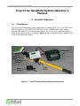
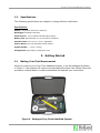
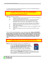
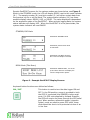
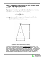
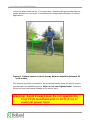
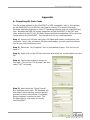
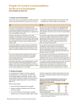
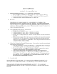
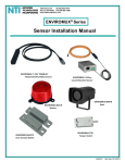
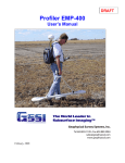
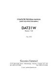
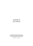
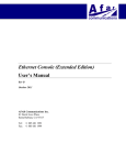
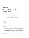
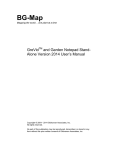
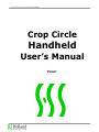
Crop Circle Handheld System Crop Circle Handheld User’s Manual From Crop Circle Handheld System Holland Scientific, Inc. 5011 South 73rd Street Lincoln, NE 68516-4236 Tel/Fax: 1 (402) 488-1226 www.hollandscientific.com [email protected] [email protected] DN: 4003. Rev 3. 7/15/11. Crop Circle Handheld System TABLE OF CONTENTS Safety and Warranty Information 1. Product Overview 1.1 Introduction 1.2 Specifications 2. Getting Started 2.1 Making Your First Measurement 2.2 GeoSCOUT User Interface 2.3 2.4 Configuring the GeoSCOUT Crop Circle Handheld Operational Overview Appendix A. Formatting SD Flash Cards B. Crop Circle Handheld Care and Maintenance C. Notes Crop Circle Handheld System SAFETY This product has been designed and tested to be a safe and “environmentally friendly” device. To ensure safe operation and to keep the product safe, the information, cautions, and warnings in this manual must be followed. Warning: Avoid Power Lines. Do not operate the Crop Circle Handheld with in 10 ft (3 m) of electrical power lines. CERTIFICATION Holland Scientific certifies that this product met its published specifications at the time of manufacture. Accuracy of the data recorded by this data acquisition system depends on the user adhering to the procedures published in this manual. WARRANTY Holland Scientific warranties this product against defects in material and workmanship for a period of one year from the date of shipment. During the warranty period, Holland Scientific will, at its option, either repair or replace products that prove to be defective. For products returned to Holland Scientific for warranty service, Buyer shall prepay shipping charges to Holland Scientific and Holland Scientific shall pay shipping charges to return the product to Buyer. However, Buyer shall pay all shipping charges, duties, and taxes for products returned to Holland Scientific from another country. LIMITATION OF WARRANTY The foregoing warranty shall not apply to defects resulting from improper or inadequate maintenance by Buyer, Buyer-supplied software or interfacing, unauthorized modification or misuse, operation outside of the environmental specifications for the product, or improper site preparation or maintenance. Information in this manual is subject to change without notice. No liability is assumed for damages resulting from the use of this information, device or software described. ----------------------- Copyright 2005-2011. Holland Scientific --------------------- Crop Circle Handheld System Crop Circle Handheld System Operator’s Manual 1. Product Overview 1.1 Introduction The Crop Circle Handheld System integrates our popular ACS-210 (or ACS430 and ACS470 sensors), GeoSCOUT GLS-400 and a 5 A-hr battery pack into a single, portable and easy-to-use scouting instrument. The Crop Circle Handheld System is ideal for plot work and crop scouting. Figure 1 below shows the main features of a Crop Circle Handheld System. Battery Pack Crop Circle Sensor GeoSCOUT GLS-400 Battery Charger Figure 1. Trigger Switch Crop Circle Handheld System components. Crop Circle Handheld System 1.2 Specifications The following specifications are subject to change without notification Specifications: Sensor: Crop Circle ACS-430 or ACS-470 Datalogger: GeoSCOUT GLS-400 Power Source: 5 A-hr Sealed Lead Acid (SLA) battery Battery Life: Approximately 8 to 10 hrs before recharging Extension Rod: 2-4 ft (0.61 -1.22 m), adjustable Sensor Mount: Two-way adjustable swivel bracket System weight: ~ 10 lbs. (4.5 kg) Storage Case: High impact, polyethylene case 2. Getting Started 2.1 Making Your First Measurement When you receive your Crop Circle Handheld system, it will be packaged as shown in Figure 2. Your system will require minimal assembly before use. Please follow the procedure outlined below in order to assemble and operate your instrument. Figure 2. Packaged Crop Circle Handheld System. Crop Circle Handheld System To begin assembling and collecting data with your Crop Circle Handheld System, please follow the steps listed below: Caution: All cables must be connected prior to powering the GeoSCOUT. Connecting a cable while the GeoSCOUT is powered may damage GeoSCOUT. Step 1) Assembly procedure: a) Connect the sensor to the swivel bracket (use the two thumbscrews threaded into the Crop Circle sensor). b) Mount the GeoSCOUT GLS-400 on to the adjustable GeoSCOUT mounting plate located next to the trigger switch (both the GeoSCOUT and its mount have Velcro applied to their mating surfaces; merely align these surfaces and lightly press together). c) Attached the sensor to the coiled cable that is connected th the trigger switch assembly. d) Last, attach the trigger switch DB-9 cable to the GeoSCOUT sensor input port. e) Connect the battery pack power plug into the GeoSCOUT power input. The Crop Circle Handheld System is now ready to operate. Note, the FieldPAK power supply may need to be recharged. Please use the AC wall-mounted battery charger provided with your Crop Circle Handheld to recharge the FieldPAK supply. To charge, connect the battery package power plug into the mating connector on the charger and then plug the charger into the wall. Warning: Avoid Power Lines. Do not operate the Crop Circle Handheld with in 10 ft (3 m) of electrical power lines. Step 2) Insert an SD flash card into the GeoSCOUT card slot. An SD flash card has the form factor shown to the right. Be sure the SD flash is formatted for the DOS FAT file system format. Flash cards supplied by Holland Scientific will be formatted with the proper file system. Note, most SD flash cards come formatted in FAT format as opposed to FAT-32. Please see Appendix A for details on formatting flash cards. When purchasing flash cards, be sure they have the SD logo on them. The GeoSCOUT is not compatible with MMC cards. Crop Circle Handheld System Step 3) Press the ON/OFF button. The GeoSCOUT start-up prompt will display followed shortly by the “Select Sys Mode” prompt. Step 4) Use the Down Arrow to select the Plot mode. Press the OK button. The GeoSCOUT will now enter the PLOT operational mode. Step 5) After the display changes, press the LOG button. The mode prompt will change from READY to PAUSE. The GeoSCOUT is now ready to begin collecting data. Simply toggle the trigger switch, and your Crop Circle Handheld System will begin collecting data. The sample number advancement is indicated on the GeoSCOUT’s display as well as the current plot number. When you are through collecting data, press the LOG button to stop the data acquisition process. This will close the data file stored on the flash card. You may now remove the flash card by pushing on the card. It will click and pop out slightly from the slot. Pull the card from slot and place it into a card reader connected to your PC in order to access your sensor data. 2.2 GeoSCOUT User Interface The front panel of the GeoSCOUT has a 2-line by 16-character LCD display and five command buttons to select operation options and to facilitate data collection. The user can navigate the GeoSCOUT’s three modes of operation using the keyboard. The 3 modes of operation are: Operational Mode Mode Description Standby This mode allows the user to enter the CONFIG Mode, LOG Mode or scroll through GPS and sensor data on the display by pressing the DISP button. This mode is entered by pressing the MENU button while the sensor is in the Standby Mode. Pressing this button while in the LOG Mode has no effect. This mode allows the user to log sensor data to a file contained on the SD flash card. Logging is initiated and terminated by pressing the LOG button. Logging can be paused and resumed by pressing the PAUSE button. Use of the DISP button allows viewing of the various sensor and GPS parameters. Configuration (CONFIG) Log Crop Circle Handheld System Sample GeoSCOUT screens for the various modes are shown below, see Figure 3. When in the STANDBY mode, the LCD will display READY next to the mode indicator (M:). The sample number (N:) and plot number (P:) will either contain data from the previous log file or will be blank. The system status indicator (M:) has three possible display values: READY, LOG, or PAUSE. The value displayed is dependent on the acquisition state of the GeoSCOUT. When actively logging data, the system status indicator will display LOG. When the GeoSCOUT is in the pause state, the system status indicator will read PAUSE. STANDBY/LOG Mode GeoSCOUT STANDBY Mode GeoSCOUT paused state while in LOG Mode GeoSCOUT LOG Mode showing Plot 1 and 35 samples recorded MENU Mode (Title Menu) GeoSCOUT CONFIG Mode, use of the up and down buttons will display the various configuration options Figure 3. Example GeoSCOUT Display Screens Keyboard button functions are defined as follows: ON / OFF This button is used to turn the data logger ON and OFF. In the ON position, power is provided to both the GPS (if connected) and SENSOR via the serial ports. For GPS units supplied by Holland Scientific, the GPS will receive its power through the GPS serial port. When auxiliary automobile power (cigarette lighter) cords are used to power GPS units, these cords should be short circuit protected via use of an in-line fuse. Crop Circle Handheld System MENU / ESC (escape) This button allows the user to enter the CONFIG mode to make changes to the GeoSCOUT’s configuration. When in the CONFIG mode, the MENU/ESC button works as the escape button to exit submenus with out making changes to settings. When changes to the GeoSCOUT configuration are complete, the menu mode can be exited by pressing MENU/ESC button to return to the STANDBY mode. DISP (Display) / UP Arrow When the GeoSCOUT is in the STANDBY and LOG modes, this button allows the user to scroll through the sensor and GPS parameters. When in the CONFIG mode, this button functions as the UP Arrow for scrolling through the various menu and submenu options. In the STANDBY and LOG modes, users can view the sensor and GPS data being collected by the GeoSCOUT. Each time the DISP button is pressed, the display screen will advance to the next data set. The first few data screens show GPS and system information while the latter screens show sensor data. PAUSE / DOWN Arrow When in the LOG mode, this button allows the user to pause the data collection process. Pressing the button again while the GeoSCOUT is paused will resume data collection. When the GeoSCOUT is in the CONFIG mode, this button functions as the DOWN Arrow to scroll backward through the various menu and submenu options. For ACS-430 and ACS-470 sensors, pressing the pause button in the READY mode will turn off power to the sensor in order to conserve battery power. The sensor will be powered down after 5 minutes of inactivity in the Ready mode. LOG / OK This button is used to commence data collection causing the GeoSCOUT to enter the LOG mode. While in the LOG mode, pressing this button will terminate data collection and close the data file written to the SD flash card. When in the CONFIG mode, this button allows the user to acknowledge Crop Circle Handheld System (i.e., “OK”) that the user wishes to change the option displayed. 2.3 Configuring the GeoSCOUT Configuration Options – When in the CONFIG mode, users can scroll through the following options using the UP and DOWN keys. Within each option, various submenu options exist and are as follows: Backlight Adjustment This feature allows the user to set four levels of backlight intensity. By using the UP and DOWN buttons, the intensity of the backlight can be changed. The intensity can be selected by pressing the OK button. Press the ESC button to return to the main menu without changing the backlight setting. Find GPS Pressing the OK button causes the GeoSCOUT to search for the proper GPS connection. Once the GeoSCOUT finds the appropriate baud rate, it will display “On-Line”. If no GPS is used, the GeoSCOUT will scan all baud rates and direct users to check the connections. GPS Logging Configuration This submenu feature allows various GPS parameters to be logged into the data file. The GPS parameters are described below: GPS Parameter Interpolate GPS (ON or OFF) Elevation (ON or OFF) Fix Type Log (ON or OFF) UTC Time Log (ON or OFF) Speed Log (ON or OFF) Course Log (ON or OFF) Description/Function This function allows spatial interpolation of data points between successive GPS location data points Antenna elevation parameter in meters *Differential fix type: 0- No Fix 1- GPS Fix 2- Differential Fix 6- Estimated Universal time stamp Vehicle speed parameter in kph Vehicle course in degrees from in a clockwise direction *Consult your GPS sensor’s user guide for accuracy specifications as they relate to fix type enumerations Annunciator Use the Up/Down Arrows to select the beeper mode. Press the OK button to except selection or press the ESC button to return to the main configuration menu. Crop Circle Handheld System Set Sensor Type Crop Circle ACS-225LR Geonics EM-38 EM-38B and EM-38DD DUALEM 1S and 2S Crop Circle ACS-470 Crop Circle ACS-430 (selecting the 430 sensor type also selects legacy ACS-210 sensors) Configure CC Sensor Set Sample Rate 2.4 Crop Circle Handheld Operational Overview 2.4.1 General Overview The Crop Circle Handheld System may be operated in one of two data acquisition modes. These modes are the MAP mode and the PLOT mode. One of these two modes is selected by the user when the GeoSCOUT is powered up. If the MAP mode is selected, a GPS is required for proper operation of the GeoSCOUT. The PLOT mode does not use the GPS signal and subsequently ignores the GPS if it is connected to the GeoSCOUT. MAP Mode: When the MAP mode is selected, the GeoSCOUT will collect both GPS and sensor data and store this data to a comma separated variable (CSV) file on the SD flash card. Data can be later retrieved and analyzed using third party map rendering software. Data collection is initiated by pressing the LOG button and data collection commences automatically. Data collection can be paused by pressing the PAUSE button. To resume data collection, press the PAUSE button again. PLOT Mode: When the PLOT mode is selected, the GeoSCOUT will collect only sensor data and save this data to a text file on the SD flash card. The file format will include a plot number (starting at 1) followed by the sample number within the plot followed finally with the sensor data. Data collection in the PLOT mode can be initiated via pressing the LOG button. The GeoSCOUT will respond by initializing the plot number and sample number on the LCD display. By pressing the PAUSE button, the GeoSCOUT will begin storing data to the SD flash card. When the PAUSE button is pressed again, data collection will stop. Pressing the pause button again will begin data collection again first by advancing the plot number and clearing the sample counter and then by saving sensor data to the SD flash file. File naming in both the MAP and PLOT modes is automatic. In the MAP, the GeoSCOUT uses the UTC Date string from the GPS as the filename with a 2 digit Crop Circle Handheld System letter index extension. This file naming convention will allow a maximum of 626 files to be created per day. For example, a MAP filename may look as follows: 101205AA.csv In the PLOT mode, the files are given the name “SITE” followed by a 4 digit numeric extension. This file naming convention will allow 10,000 plot files to be created and stored on the SD flash card. For example, a PLOT filename may look as follows: SITE0000.CSV A sample portion of a GeoSCOUT data file is shown in Figure 4. The data file contains plot data collected from a Crop Circle Handheld System. This sample fiel has data collected from three plots (1, 2 and 3). The sensor fields in this file, SF1 to SF6, represent the sensor elapsed time, sensor mode, ACS-210 internal sample number, normalized difference vegetative index (NDVI), near infrared band reflectance (NIR) and visible band reflectance (VIS), respectively. Additional vegetative indices may be calculated from the reflectance band information. Please refer to the Crop Circle Sensor User’s Manual for a list of indices and data field listing. Crop Circle Handheld System Figure 4. Sample data set collected by Crop Circle Handheld System in PLOT mode using ACS-210 sensor. 2.4.1 Sensor Usage Considerations Figure 5 diagrammatically shows an ACS-430 (or ACS-470) sensor mounted at height h above a plane target. The width of the projected beam when mounted height h above a target is defined by the following equation, θ w=2 h tan =0.82 h 2 where is the angular FOV in degrees (~40-45 degrees for the ACS-430), w is the projected beam width and h is the height of the sensor above the target. θ Figure 5. Sensor Field-of-View (FOV). The sensor should be positioned between 30 and 48 inches from the top of the plant canopy for optimal measurement performance, see Figure 6. Please note however, the sensor’s measurement range is ~10 to 120 inches. When selecting a plant-to-sensor measurement distance, take in consideration the FOV angle of the sensor. For example, the beam width at canopy level will be ~0.82 times the distance between the sensor and canopy. At a plant-to-sensor distance of 36 Crop Circle Handheld System inches the beam width will be ~20 inches wide. Selecting the appropriate plant-tosensor distance can be useful in minimizing soil background reflectance in certain applications. 30 to 48 inches Figure 6. Optimal sensor-to-plant canopy distance should be between 22 to 60 inches. The sensors should be connected to the mounting bracket using the thumb screws provided with the handheld system. Note: do not over tighten bolts! Excessive torque will strip the tapped threads in the sensor body. Warning: Avoid Power Lines. Do not operate the Crop Circle Handheld with in 10 ft (3 m) of electrical power lines. Crop Circle Handheld System Appendix A. Formatting SD Flash Cards The file system utilized by the GeoSCOUT is DOS compatible, that is, files written by the GeoSCOUT to the SD flash card can be read by PCs running Microsoft Windows operating systems or other PC operating systems that can read DOS text files. Because the DOS file system supported by the GeoSCOUT is the FAT type (also referred to as FAT-16), SD flash cards should be formatted as FAT so as to be recognized by the GeoSCOUT. The procedure to do so is outlined below. Step 1) Insert your SD flash card into a SD flash card reader connected to your computer. Note, if do not have a SD flash card reader, you will need to purchase one at your local electronics store. Step 2) Select the “My Computer” icon on the desktop screen. Click the icon to open it. Step 3) Right click on the SD flash card icon and select the format option from the list. Step 4) The format window is shown on the right. Click on the “File System” tab and select “FAT” as shown. Step 5) Next check the “Quick Format” Box and then press start. MS Windows will then begin the formatting process and will prompt you when the process is complete. When complete, remove the card. The SD flash Card is now ready for use by the GeoSCOUT. Crop Circle Handheld System B. Crop Circle Handheld Care and Maintenance Maintaining the handheld system is relatively easy and straight forward. Proper care and storage of the system will help ensure reliable and repeatable operation. Follow the recommendations below to properly care for your Crop Circle Handheld. Before use: Inspect connectors prior to use. Clean to remove any dust or soil from interfering with connectors. Use a moist, soft cotton cloth to clean surfaces and enclosure. Never use an abrasive cleaner or rough cloth. Never use a solvent-based cleaner on the enclosure. Storage: Between field surveys and after the seasonal usage, the handheld system should be stored at room temperature and in low humidity environment. Disconnect all cables and store the handheld system in its storage case. The 5 A-hr battery pack should be periodically float charged during long storage periods. Cables: Check all cables before and after use. Look for damage to pins and wire sheaths. Note: bare or frayed wires can cause an electrical hazard that may present a danger to the user/by-stander and/or damage the instrumentation. If damage is noticed, contact Holland Scientific for repair or replacement of cable. Crop Circle Handheld System C. Notes