1
Modicon STB
IP 20 distributed
inputs/outputs
®
Catalog
2010
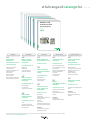
A full range of catalogs for . . . . . .
Modicon® STB
IP 20 distributed
inputs/outputs
Catalog
2010
Detection
Automation
Automation
Operator dialog
Motion and Drives
&
&
&
&
&
Global Detection
Electronic and
electromechanical sensors
Modicon® Quantum™
automation platform
Catalog 2009
Modicon® Momentum™
distributed I/O and control
Control and signalling
components
MKTED208052EN
MKTED205061EN
MKTED208031EN
Lexium® 32 Servo Drives
motion control
Catalog 2009/2010
MKTED208011EN-US
Photo-electric sensors
Proximity sensors
Capacitive proximity sensors
Ultrasonic sensors
Limit switches
Pressure switches
Rotary encoders
Radio frequency identification
Machine cabling accessories
Safety PLCs
Safety CPUs
Unity™ Concept™ and
ProWORX™ software
&
Modicon® Premium™
automation platform
Catalog 2010
MKTED208054EN-US
Unity processors
PL7 processors
Communication software
&
Modicon® M340™
automation platform
Catalog 2010
DIA6ED2081007EN-US
PLCs
Discrete, analog I/O and
application-specific solutions
Communication
DIA3ED2090202EN
Control and signalling units
Control stations & enclosures
Cam switches
Beacons and indicator banks
Pendant control stations
Controllers
Emergency stops
Foot switches
Controller base
Discrete, analog I/O
Communication
&
&
Twido® programmable
controller and TwidoSuite™
software
&
Automation functions,
relays, interfaces and
power supplies
MKTED207031EN
Smart relays
Timing relays
Measurement & control relays
Analog interfaces
Counters
Plug-in relays
Interfaces for discrete signals
Power supplies & transformers
Magelis®
Human/Machine Interfaces
Catalog 2010
MKTED206071EN-US
Operator interface terminals
Industrial PCs
HMI and SCADA PC-based
software
Software
Vijeo Designer
Operator terminal software
Software
PLCs and safety controllers
programming software
Not all products shown in this catalog are available in every country. Check individual country’s web site or Sales Office for product availability.
See our web site: www.schneider-electric.us/
DIA7ED2090405EN-US
Motion controllers
Servo drives and Servo motors
Stepper motors and drives
Integrated drives
Modicon Premium
motion control modules
&
Soft starters and variable
speed drives
MKTED206111EN
Soft starters and variable speed
drives
Software
Software for drives
Motor control programming
software
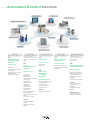
. . . . . . Automation & Control functions
Motor control
&
Motor starter solutions
Control and protection
components
MKTED205103EN
Contactors
Circuit-breakers, fuse carriers
Thermal relays
Combinations, motor controllers
Mounting solutions
Motor starter mounting kits
Machine safety
This catalog contains
Automation and Control function
products relating to machines
Safety
&
Preventa™
Machine Safety Products
Catalog 2009
MKTED208051EN-US
Safety PLCs
Safety controllers
Safety monitors
Safety solutions on AS-Interface
cabling system
Safety switches
Safety light curtains
Safety mats
Emergency stops
Control stations
Enabling switches
Foot switches
Beacons & indicator banks
Switch disconnectors
Thermal-magnetic motor circuit
breakers
Enclosed D.O.L. starters
Software
XPSMFWIN configuration
software
XPSMCWIN configuration
software
Interfaces and I/O
Power supplies
&
&
Terminal blocks
Phaseo® power supplies
and transformers
MKTED207011EN
Terminal blocks
Cable ends
&
Modicon® STB
IP 20 distributed
inputs/outputs
Catalog 2010
MKTED208053EN-US
Modules for automation station
Network interfaces
Power distribution
Digital I/O, analogs and
application-specific
Software
STB configuration software
Systems & architectures
This catalog contains
Automation and Control function
products relating to
Communication
DIA3ED2061209EN
&
Switch mode power supplies
Filtered rectified power supplies
Transformers
Machine & Installations with
industrial communication
MKTED207012EN
Preferred implementations
Ethernet TCP/IP, the universal
communication standard
CANopen for machines and
installations
AS-interface, simple and safe
Products
Human-Machine interface
Controllers and PLCs
Field devices
Infrastructure and wiring
Gateways
Software and tools
Collaborative Automation
Partner Program & Partners
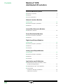
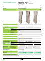
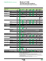
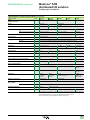
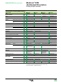
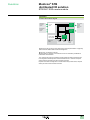
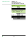
Contents
Modicon® STB
distributed I/O solution
Open and Modular System
�Introduction, composition. . . . . . . . . . . . . . . . . . . . . . . . . . . . . . . . . . . . . . . . . . . . 6
�Description. . . . . . . . . . . . . . . . . . . . . . . . . . . . . . . . . . . . . . . . . . . . . . . . . . . . . . 9
�Functions, specifications. . . . . . . . . . . . . . . . . . . . . . . . . . . . . . . . . . . . . . . . . . . 15
Network Interface Modules
Selection guide . . . . . . . . . . . . . . . . . . . . . . . . . . . . . . . . . . . . . . . . . . . . . . . . . . 18
�Introduction, description, specifications. . . . . . . . . . . . . . . . . . . . . . . . . . . . . . . 20
�References . . . . . . . . . . . . . . . . . . . . . . . . . . . . . . . . . . . . . . . . . . . . . . . . . . . . 23
Internal Bus Extension Modules
�Specifications, references. . . . . . . . . . . . . . . . . . . . . . . . . . . . . . . . . . . . . . . . . 26
Power Distribution Modules
�Introduction, description, specifications. . . . . . . . . . . . . . . . . . . . . . . . . . . . . . . 28
�References . . . . . . . . . . . . . . . . . . . . . . . . . . . . . . . . . . . . . . . . . . . . . . . . . . . . 33
Digital Input/Output Modules
Selection guide . . . . . . . . . . . . . . . . . . . . . . . . . . . . . . . . . . . . . . . . . . . . . . . . . . 34
�Introduction, description, specifications. . . . . . . . . . . . . . . . . . . . . . . . . . . . . . . 40
�References . . . . . . . . . . . . . . . . . . . . . . . . . . . . . . . . . . . . . . . . . . . . . . . . . . . . 48
�Connections. . . . . . . . . . . . . . . . . . . . . . . . . . . . . . . . . . . . . . . . . . . . . . . . . . . . 52
Analog Input/Output Modules
Selection guide . . . . . . . . . . . . . . . . . . . . . . . . . . . . . . . . . . . . . . . . . . . . . . . . . . 56
�Introduction, description, specifications. . . . . . . . . . . . . . . . . . . . . . . . . . . . . . . 62
�References . . . . . . . . . . . . . . . . . . . . . . . . . . . . . . . . . . . . . . . . . . . . . . . . . . . . 70
�Connections. . . . . . . . . . . . . . . . . . . . . . . . . . . . . . . . . . . . . . . . . . . . . . . . . . . . 74
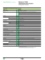
Application-specific Modules
�Parallel Interface for TeSys® motor starters, model U
and TeSys® Quickfit applications . . . . . . . . . . . . . . . . . . . . . . . . . . . . . . . . . . . . 80
�Parallel Interface for Tego™ Power applications. . . . . . . . . . . . . . . . . . . . . . . . . 86
�Counter module
v Introduction, description, specifications. . . . . . . . . . . . . . . . . . . . . . . . . . . . . 88
v References, connections. . . . . . . . . . . . . . . . . . . . . . . . . . . . . . . . . . . . . . . . 92
4
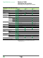
Dimensions
�Dimensions . . . . . . . . . . . . . . . . . . . . . . . . . . . . . . . . . . . . . . . . . . . . . . . . . . . . 94
Configuration Software
�Introduction . . . . . . . . . . . . . . . . . . . . . . . . . . . . . . . . . . . . . . . . . . . . . . . . . . . . 96
�Functions. . . . . . . . . . . . . . . . . . . . . . . . . . . . . . . . . . . . . . . . . . . . . . . . . . . . . . 97
�References . . . . . . . . . . . . . . . . . . . . . . . . . . . . . . . . . . . . . . . . . . . . . . . . . . . 101
Combinations
�Momentum™ PLC 171 CBB 970 30 processer. . . . . . . . . . . . . . . . . . . . . . . . . 102
�Combination with Magelis® display units
and human/machine interface terminals . . . . . . . . . . . . . . . . . . . . . . . . . . . . . 108
�High-density I/O modules
and Modicon® Telefast® cabling system ABE 7. . . . . . . . . . . . . . . . . . . . . . . . . . 110
Phaseo® Regulated Power Supplies
�Introduction . . . . . . . . . . . . . . . . . . . . . . . . . . . . . . . . . . . . . . . . . . . . . . . . . . . 116
�Specifications. . . . . . . . . . . . . . . . . . . . . . . . . . . . . . . . . . . . . . . . . . . . . . . . . . 119
�Combinations of Phaseo power supplies with STB modules. . . . . . . . . . . . . . 121
�References, dimensions . . . . . . . . . . . . . . . . . . . . . . . . . . . . . . . . . . . . . . . . . . 121
Services
�Automation product certifications. . . . . . . . . . . . . . . . . . . . . . . . . . . . . . . . . . . 122
�Power consumption. . . . . . . . . . . . . . . . . . . . . . . . . . . . . . . . . . . . . . . . . . . . . 124
�Product reference index. . . . . . . . . . . . . . . . . . . . . . . . . . . . . . . . . . . . . . . . . . . 127
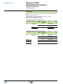
Advantys™, Altistart®, Altivar®, Concept™, ConneXium™, FactoryCast™, Fipio®, Fipway®, Lexium®, Magelis®, M340™, Modbus®, Modbus Plus™,
Modicon®, Momentum™, OSItrack™, Phaseo®, PowerSuite™, Premium™, Preventa™, ProWORX 32™, Quantum™, Schneider Electric, Telefast®,
TeSys®, Transparent Ready®, TSX Micro™, Twido®, TwidoSoft™, TwidoSuite™, Unity™, Unity™ Pro, Vijeo Designer™, Vijeo Look™ X-Way® are
trademarks or registered trademarks of Schneider Electric. Other trademarks used herein are the property of their respective owners.
5
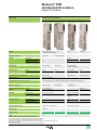
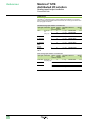
Introduction
Modicon® STB
distributed I/O solution
Open and modular system
Introduction
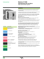
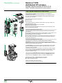
To meet the needs of machine manufacturers and users, automation architectures
have been decentralized, while delivering performance comparable to that of
centralized systems.
Architectures installed as close to the machine as possible reduce the time and cost
of wiring for sensors and actuators, while increasing system availability.
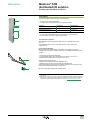
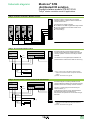
The Modicon® STB distributed I/O solution is an open, modular input/output system
and makes it possible to design automation stations managed by a master controller
via a bus or communication network. These stations can be used to connect:
b Motor starters
b Variable speed drives
b Magelis® communication terminals HMI
b Approved third-party products via the CANopen bus: Festo®, Parker® valves,
FTB IP 67 distributed I/O, ATV variable speed drives, encoders, etc.
Modicon software guides users through the design phase, startup, and maintenance
of the system. This single software package covers the Modicon STB, OTB, FTB,
and FTM ranges.
These station components are electronic modules mounted on one or more DIN rails.
These clusters of modules, known as segments, carry a bus from end to end of each
station. The station bus provides power distribution, signal sensing, and power
management to compatible modules, in the form of a wiring management system.
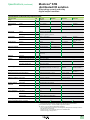
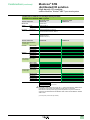
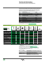
Color code
Type of module
NIM network interface
EOS/BOS station extension
CANopen extension
24 V c digital inputs
24 V c power distribution
24 V c digital outputs
115 V a or 230 V a digital inputs
115/230 V a power distribution
115/230 V a digital outputs
Digital relay outputs
TeSys® U, TeSys® Quickfit and Tego™
Power interface, counter module
Analog inputs
Analog outputs
6
The Modicon STB I/O family is divided into 2 groups of modules:
b Basic modules: A complete set of low-cost modules and network interfaces, with
simplified operating modes.
b Standard modules: An extended offer of I/O modules, with additional functions:
configurable parameters, extended operating modes.
Both the basic and standard ranges comprise:
b NIM modules: network interfaces
b Power Distribution Modules (PDM) (24 V c and 115/220 V a)
b I/O modules:
v Digital I/O (24 V c and 115/220 V a)
v Analog I/O (10, 12 and 16-bit resolution)
v Relay outputs (24 V c coil and 24 V c or 115/230 V a contact)
b Application-specific I/O module: Counter module
b Dedicated modules:
v for TeSys® motor starters, model U and TeSys® Quickfit applications
v for Tego™ power applications
b EOS (end of segment) and BOS (beginning of segment) modules.
b External equipment support module on CANopen extension
Standard and basic modules can be combined on the same station. This
combination allows a wide range of functions. See the table on page 15.
The sensors and actuators are connected to the I/O modules via a removable screw
or spring-type terminal.
Standard Modicon STB modules are hot-swappable, provided the network interface
modules are also standard type.
Modicon STB distributed I/O have a protection rating of IP 20. For installations in
production workshops, they must be installed in protective casings with at least an IP
54 rating (in compliance with IEC 60950 or NEMA 250). See page 122.
Introduction (continued)
Modicon® STB
distributed I/O solution
Open and modular system
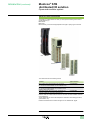
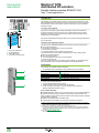
Modicon® STB connection kit
The Modicon® STB kit references allow you to acquire the following items under a
single reference (1) :
b A module
b Its base
b If necessary, a choice of the appropriate screw-type or spring-type connectors
Base
Module
Screw-type
connectors
Spring-type
connectors
The references are in the following format:
Content
Typical reference
Base, module, screw-type and spring-type connectors
Base, module, screw-type connectors
for 16-channel modules STB DDI 3725 and STB DDO 3705
STB ppp pppp K
STB DDp 37p5 KS
Base, module, spring-type connectors
for 16-channel modules STB DDI 3725, STB DDO 370 and
STB EHC 3020 counter module
STB ppp pppp KC
NIM network module, base not required, supplied with one
connector of each type: screw-type and spring-type
STB Npp pppp
Modicon STB I/O modules without a base or connector are also available under the
usual references.
These references are used in the descriptions contained in this catalog (functions,
specifications, etc).
Details of the kits and their contents are given on the “References” pages.
(1) The STB EPI 1145 module is not available with a connector kit.
7
Composition
Modicon® STB
distributed I/O solution
Open and modular system
Composition of a Modicon® STB station
A Modicon® STB station is made up of one or more segments comprising Power
Distribution Modules (PDM) and I/O modules.
A Modicon STB station starts with a network interface module and ends with a bus
terminator supplied with this module. A station can be made up of a single segment
or a primary segment and up to 6 extension segments, chained by End Of Segment
(EOS) and Beginning Of Segment (BOS) extension modules.
On each segment:
b The PDMs must be placed immediately to the right of the network interface
modules or extension modules.
b The I/O modules are placed to the right of the PDM module supplying them with
power.
b Every module, PDM or I/O, is held in a base on the DIN rail (1). Three module and
base widths are possible. The overall width needed for a segment on a DIV rail is the
combined widths of the network interface module, the bases and any bus
termination.
The bases help ensure the continuation of the internal bus, the auto-addressing of
the modules, and the separated and isolated distribution of the internal power
supplies, actuators and sensors.
The advantages of this arrangement are:
b Unplugging modules:
v When switched off (cold swap), modules can be unplugged very quickly.
v When switched on (hot swap), I/O modules can be unplugged provided the
network interface module is the standard type.
b Output power supply independent of inputs: For example, if an output power
supply is cut by a Preventa™ safety module, the inputs are still managed.
b Immunity of inputs: For example, the closing of power contactors (controlled by
outputs) does not disturb analog input measurements.
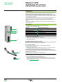
The Network Interface Module (NIM)
This module manages communications on the station bus. It acts as a gateway for
exchanges with the fieldbus or network master. Eleven NIM models are available for
seven fieldbuses or networks: Ethernet TCP/IP (standard only), CANopen, Modbus
Plus™ (standard only), Fipio® (standard only), InterBus®, Profibus DP™ and
DeviceNet™ interface modules.
(1)Each module, with the exception of the NIM network interface module, requires a base and
one or more specific connectors.
8
Description
Modicon® STB
distributed I/O solution
Open and modular system
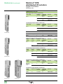
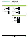
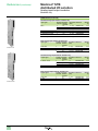
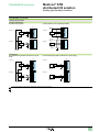
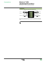
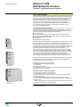
Description of basic Modicon® STB
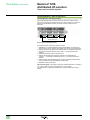
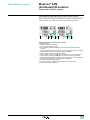
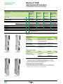
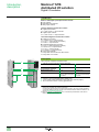
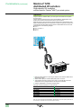
Basic Modicon® STB: Single segment
With a basic network interface module it is possible to create a station with only one
segment (single segment) with up to 12 I/O modules. This excludes segment power
distribution modules, a network interface module and a bus termination.
Single segment basic Modicon STB
1 2
3
4
5
6
12 I/O
modules max.
In the example above, the single segment contains:
1 STB Npp 1010: A Network Interface Module (NIM). It is placed at the beginning of
the primary segment. Each station must have only one NIM module.
2 STB PDT 2105: A Power Distribution Module (PDM). It is installed immediately to
the right of the NIM and distributes the 115/230 V a to the AC powered I/O
modules.
3 STB DAp: Digital I/O modules powered with AC.
4 STB PDT 3105: PDM power distribution module. It is installed after the
115/230 V a I/O modules. It distributes the 24 V c to the DC powered I/O
modules.
5 STB AVp and STB ACp: Analog I/O modules powered with DC are installed after
the PDM module.
6 STB XMP 1100: Bus termination supplied with the NIM network interface module.
Internal power supply: The NIM network interface module STB Npp provides a
5 V c logic voltage (1.2 A) from an external 24 V c power supply.
9
Description (continued)
Modicon® STB
distributed I/O solution
Open and modular system
Standard Modicon® STB configurations
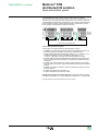
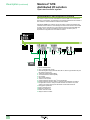
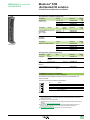
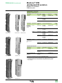
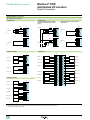
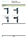
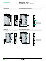
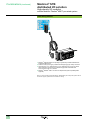
Standard Modicon® STB: Single segment
With a NIM standard network interface module it is possible to create a station
with only one segment (single segment) with up to 32 I/O modules. This excludes
segment power distribution modules, a network interface module and a bus
termination.
1 2
3
4
5
2
3
4
5
6
32 I/O modules max.
Single segment standard Modicon STB
In the example above, the primary segment contains:
1 STB Npp 2212: A standard Network Interface Module (NIM). It is placed at the
beginning of the primary segment. Each station must have only one NIM module.
2 STB PDT 210p: A Power Distribution Module (PDM). It is installed immediately to
the right of the NIM and distributes the 115/230 V a to the AC powered I/O
modules.
3 STB DAp: Digital I/O modules powered with AC.
4 STB PDT 310p: PDM power distribution module. It is installed after the
115/230 V a I/O modules and distributes the 24 V c to the DC powered I/O
modules.
5 STB AVp, STB ACp, STB DDp: Digital or analog I/O modules powered with DC.
They are installed after the PDM STB PDT 310p module.
6 STB XMP 1100: Bus termination.
Internal power supply: The auxiliary power supply module STB CPS 2111 supplies a
5 V c logic voltage (1.2 A) from an external 24 V c power supply.
The STB CPS 2111 should be associated with an STB PDT p10p power supply
module
10
Description (continued)
Modicon® STB
distributed I/O solution
Open and modular system
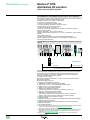
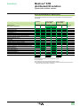
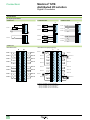
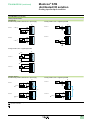
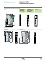
Standard Modicon® STB: Primary segment with extension segments
The station bus can support the primary segment with up to 7 extension segments.
A standard NIM network interface module supports up to 32 I/O modules (excluding
power distribution modules, network interface module, bus termination, auxiliary
power supplies, and EOS/BOS bus extension modules).
1 2
3
4
7
5 2
3
2
3
4
7
5 2
3
6
15 m max. with 32 I/O modules max.
Standard Modicon STB with 3 segments
The segments of the above Modicon STB configuration comprise:
1 STB Npp 2212: A NIM network interface module. It is placed at the beginning of
the primary segment. Each station must have only one NIM module.
2 STB PDT p100: A PDM power distribution module (24 V c or 115/230 V a). It is
installed immediately to the right of the NIM and distributes 24 V c or
115/230 V a depending on the type of I/O modules located on the right.
3 STB AVp, STB ACp, STB DDp, STB DAp and STB DRp: I/O modules powered
with DC or digital modules powered with AC are placed immediately to the right
of the PDM.
4 STB XBE 1100: EOS bus extension module is always installed in the rightmost
slot in the primary or extension segment and it extends the station bus to another
segment.
5 STB XBE 1300: BOS bus extension module is installed at the beginning of each
extension segment.
6 STB XMP 1100: Station bus termination (1).
7 STB XCA 100p: Station bus extension cables.
Internal power supply for secondary segments: The BOS bus extension module
STB XBE 1300 provides a 5 V c logic voltage from an external 24 V c power supply.
(1)Supplied with the corresponding NIM network interface module.
11
Description (continued)
Modicon® STB
distributed I/O solution
Open and modular system
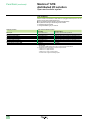
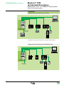
Standard Modicon® STB: CANopen extension module - device integration
The CANopen extension module STB XBE 2100 can be used to connect, at the end
of the segment, external CANopen devices such as:
v Modicon® FTB IP67 I/O, in plastic or metal casing
v ATV31/61/71 variable speed drives
v Festo® CPV-CO2 electro-pneumatic valves
v Parker® P2M2HBVC11600 electro-pneumatic valves
v Balluff® Micropulse® BTL5 linear encoders
v Osicoder absolute rotary encoders (1)
The number of CANopen external devices depends on the station's standard
network interface module:
CANopen, DeviceNet™: Up to 7 external devices.
Ethernet TCP/IP Modbus®, Modbus Plus™, InterBus®, Profibus DP™, Fipio® interface
modules
Up to 12 external devices.
The data rate of the internal bus is set to 500 Kbps with the Advantys™
STB SPU 1ppp configuration software. This speed applies to Modicon STB
modules and external devices.
Standard Modicon STB: Application-specific modules, preferred module and
devices
1 2
3 4
5
6 8
9
10
9 11 3 4 12 13
7
15 m max.
14
15
CANopen devices
12/60 m max.(2)
32 I/O modules or external devices
Standard Modicon STB with CANopen devices
A standard network interface module supports up to 32 I/O modules and CANopen
devices (excluding power distribution modules, network interface module, bus
termination, auxiliary power supplies, EOS/BOS bus extension modules and
CANopen STB XBE 2100 extension module).
The station bus can support:
b Preferred modules (available later). This type of preferred module is installed
between two segments.
b Standard CANopen devices.
The station bus illustrated above contains:
1 STB Npp 2212: A Network Interface Module (NIM)
2 STB PDT 3100: A 24 V c Power Distribution Module (PDM)
3 STB EHC 3020: 1-channel counter module
4 STB EPI 1145: Parallel interface module
5 STB DDI 3420: Digital input modules
6 STB EPI 2145: Module for TeSys® starter-controllers, model U (3)
7 TeSys U or TeSys Quickfit starter-controller
8 STB XBE 1110: EOS bus extension module
This is always installed in the rightmost slot in the primary or extension
segment, and is used to extend the station bus to another segment.
9 STB XCA 100p: Station bus extension cables
10Preferred module
11STB XBE 1300: BOS bus extension module placed at the beginning of the segment
12STB ACp: Analog I/O modules
13STB XBE 2100: CANopen extension module (up to 12 devices per station)
14Modicon FTB IP67 I/O
15ATV variable speed drive
(1)To obtain the latest list of approved equipment on the Modicon STB station extension, please
consult your Regional Sales Office or visit www.schneider-electric.us.
To validate a new product, please consult your Regional Sales Office.
(2)Total length of extension CANopen segment: 12 m as standard, 60 m in accordance with the
CAN wiring rules described in the CANopen setup document no. 31010857 (in English)
available on www.schneider-electric.us.
(3)Refer to the "Automation & Control - Motor starter solutions - Control and protection
components" catalog.
12
Description (continued)
Modicon® STB
distributed I/O solution
Open and modular system
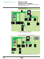
Standard Modicon® STB: TeSys® starter-controller model U, preferred
Modicon® STB provides TeSys® U with additional I/O and acts as a gateway to any
upstream fieldbus or communication network connected by Modicon STB.
1
6
6
9
5
2
34
7
5
5
8
6
6
10
4
9
7
11 12
Modicon STB LULC15 communication modules
1 Modicon STB I/O.
2 Network interface module (NIM).
3 24 V DC power supply for LULC15.
4 End of segment (EOS) STB XBE 1100 used to mount the preferred TeSys U
modules.
5 Angled cable with a station bus extension cable connector at each end, providing
the bus signals and the internal power supply (LU9RCDpp).
6 Modicon STB LULC15 communication modules.
7 TeSys U starter-controller (LUBpp) with an advanced control unit (LUCB/C/D).
8 TeSys U starter-controller (LUBpp) with a multifunction control unit (LUCM).
9 Angled cable with a station bus extension cable connector at each end, providing
the bus signals and the internal power supply (LU9RDDpp).
10STB XBE 1300 beginning of segment.
11TeSys U controller (LUTM) with a multifunction control unit (LUCMT).
12TeSys U termination (LU9RFL15).
13
Modicon® STB
distributed I/O solution
Description (continued)
Open and modular system
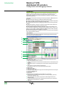
Standard Modicon® STB configurations (continued)
NIM network interface modules STB Npp 2212 and STB Npp 1010, located at the
beginning of each station, are gateways for exchanging data between the network or
bus master PLC and the Modicon® STB automation station.
Standard STB Npp 2212 modules can also be used to configure and address the
installation external devices. These settings are stored in the module's internal RAM
or Flash memory. Optionally, they can be saved to the 32 Kb removable SIM card
STB XMP 4440 – except for the address of the network connection point, to
duplicate the configuration from one station to another.
1
8
7
2
4
5
9 6
10
596
12
13
14
15
16
11
3
1 Bus or network master.
2 24 V c external power supply.
3 HMI with Magelis® display terminals XBT, XBT G, XBT GT type Modbus link (see
link cables on page 109).
4 A Network Interface Module (NIM).
5 A Power Distribution Module (PDM).
6 I/O modules.
7 Second STB segment.
8 Another control system.
9 Parallel interface module for Tego™ Power application.
10Parallel interface module for TeSys® U and TeSys Quickfit starter-controllers.
11Configurable Preventa™ safety controller XPS MC connected on the power
supply to the outputs of the power distribution module STB PDT p100.
12ATV variable speed drive.
13Festo® solenoid valves.
14Modicon FTB IP67 I/O.
15Parker® solenoid valves.
16TeSys U starter-controller.
14
Functions
Modicon® STB
distributed I/O solution
Open and modular system
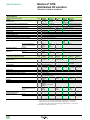
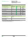
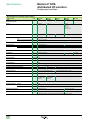
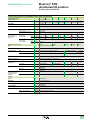
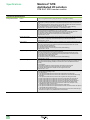
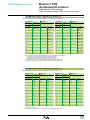
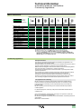
Basic/standard Modicon® STB functions
The table below describes the main functions of the basic and standard Modicon®
STB ranges:
I/O modules
Modicon® STB
Max. number of I/O modules
Removable terminals
Mechanical keying pin
Cold swapping
Hot swapping (1) (3)
Separate power supply to sensors and actuators
Built-in electronic protection of outputs
Electronic protection of power supply provided by
Modicon STB for the sensors
Protection of power supplies by built-in removable fuse
Status LEDs
Compatible with all types of network interface module
CANopen extension - device integration
Compatible with local HMI (Magelis® display terminals)
Default configuration
Assistance with design, startup, and maintenance using
Modicon software (4)
Configurable I/O parameters (4)
Built-in reflex functions
Removable memory card (4) (5)
Advanced diagnostics (4)
Internal software (firmware) update
Basic
(2)
Standard
Network interface
modules (NIM)
Power distribution
modules (PDM)
Basic
12
Basic
Standard
32
(2)
(3)
Standard
See page
8 to 11
–
41
12
12
28
–
–
–
–
–
12
108
96
96
97
100
20
98
22
Function available
Function not available
Not applicable
(1)See page 16.
(2)Requires the use of standard power distribution modules.
(3)Fuse protection.
(4)Requires the use of a standard network interface module.
(5)For assistance with the station internal settings, simplifies inoperative device replacement
(IDR) and copying of the station configuration.
15
Functions (continued)
Modicon® STB
distributed I/O solution
Open and modular system
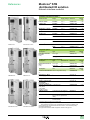
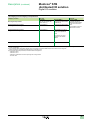
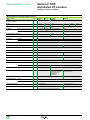
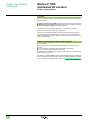
Hot swapping
When a module on the Modicon® STB station is unplugged while the power is on, the
behavior of the other modules depends on:
b the type of NIM network interface module (basic/standard)
b the parameter settings of standard type I/O modules:
v mandatory/optional module
v configured fallback type, per channel
Swapping a module
Basic input
Standard input optional
Standard input mandatory
Basic output
Standard output optional
Standard output mandatory
Power distribution module (PDM)
Network interface module (NIM)
16
Type of network interface module
Basic NIM
Standard NIM (1)
Outputs fall back to 0
The other outputs remain operational
Outputs fall back to 0
The other outputs remain operational (1)
Outputs fall back to 0
Fallback of other outputs according to configuration (1)(2)
Outputs fall back to 0
The other outputs remain operational
Outputs fall back to 0
The other outputs remain operational (1)
Outputs fall back to 0
Fallback of other outputs according to configuration (1)(2)
Prohibited
Prohibited
Prohibited
Prohibited
(1)Fallback level set by the Modicon STB SPU 1ppp software on standard I/O modules with a
standard NIM.
The STB SPU 1ppp software cannot be connected on basic NIM modules.
(2)The fallback state is adjustable on standard output modules:
- Fallback to 0 for digital modules
- Fallback to 1 for digital modules
- Fallback to any value on analog outputs
- Hold last value on digital and analog outputs
Modicon® STB
distributed I/O solution
Specifications
Open and modular system
Operating environment
Modicon® STB devices comply with the following certifications (1):
b UL
b CSA
b C-Tick
b GOST
b CE
b FM Class I, division 2, groups A, B, C and D T4A @ 70°C (158°F)
v ATEX is now available : ATEX 3G – II 3 G Ex nA IIC T4 Ta=0 to 60°C (32 to 140°F)
They benefit from merchant navy certifications issued by shipping classification
societies:
b ABS (USA)
b BY (France)
b DNV (Norway)
b GL (Germany)
b LR (Great Britain)
b RINA (Italy)
v RMRS (IEC, pending)
They are designed for use in industrial environments of pollution class 2, in
applications of over voltage category II (as defined in publication IEC 60664-1) and
at altitudes of up to 2000 m, without reduction in load.
General environmental specifications
Parameter
Protection
Operating temperature
Storage temperature
Specifications
IP 20, Class 1. Ref. EN 61131-2
Standard
Extended
°C (°F)
°C (°F)
Maximum relative humidity
0 to 60 (32 to 140)
-25 to 70 (-13 to 158) (2)
-40 to 85 (-40 to 185)
95% relative humidity at 60°C (140°C) (without condensation)
Sinusoidal vibration
Hz
10 to 58 at ± 0.35 mm
58 to 150 at 5 g on a 15 mm DIN rail
58 to 150 at 3 g on a 7.5 mm DIN rail
Shock
g
30 peak for 11 ms,
semi-sinusoidal wave for 3 shocks per axis. Ref. IEC 88, reference 2-27
(1)Certifications for all automation products (see page 122).
(2)Temperature range available on certain Modicon STB modules. See the specifications pages.
Note: restrictions on power supply voltage. The power supply voltage of NIM’s modules,
STB XBE 1100/1300, STB CPS 2111, STB PDT 3100 modules, and any external power supply
are limited as follow, depending on the operating temperature range:
- range -25 to 0°C (-13 to 32°F): the power supply voltage range is c 20.4 to 30 V.
- range 0 to 60°C (32 to 140°F): the power supply voltage range is c 19.2 to 30 V.
- range 60 to 70°C (140 to 158°F): the power supply voltage range is c 19.2 to 26.5 V.
17
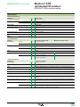
Selection guide
Modicon® STB
distributed I/O solution
Network interface modules
Applications
Data exchange between master PLC and Modicon® STB I/O modules
Bus or network type
Ethernet TCP/IP network
CANopen bus
Bus or network type
Industrial LAN
CAN fieldbus
Physical interface
10 BASE-T
ISO 1198
Data rate
10 Mbps
10 Kbps to 1 Mbps depending on bus length
Double shielded twisted pair via Ethernet
ConneXium™ cabling system
Double shielded twisted pair
Number of devices
(1)
256 max. per segment,
unlimited with switches
127 slaves
Maximum length
100 m according to 802.3 standard
1000 m with ConneXium cabling system
> 3000 m with fiber optic connection
From 30 m (1 Mbps) to 5000 m (10 Kbps)
Number of I/O modules per
Modicon® STB station (1)
Standard NIM: 32 modules max. on 1 primary
segment and 6 extension segments max.
Standard NIM: 32 modules max. on 1 primary
segment and 6 extension segments max.
Basic NIM: 12 modules max. on 1 primary
segment
Supply voltage
24 V c not isolated (19.2 to 30 V)
Logic power supply
Provides 5 V c logic power to the I/O modules of a station (1200 mA)
CANopen devices supported
12 devices max. (2)
Structure
Medium
Configuration
Features of NIM modules
(Network Interface
Modules)
Services used
- Embedded Web (configuration, diagnostics
and access to variables)
- Modbus TCP/IP
- SNMP agent
- DHCP client service
Operating temperature (3)
0 to 60°C (32 to 140°F) (4)
Type of NIM module
Standard
STB NIP 2212
STB NCO 2212
STB NCO 1010
Basic (5)
Pages
- Process Data Object (PDO)
- Service Data Object (SDO)
- Network management (NMT)
23
(1)One Modicon STB station corresponds to 1 device on the bus or the network.
(2)Depending on the nature of the CANopen devices, this maximum number may be limited to 7.
(3)Horizontal mounting.
(4)STB Npp 2212 standard modules: -25 to 70°C (-13 to 158°F), see specifications on page 22.
(5)Does not support the CANopen bus extension module, hot swapping, or Modicon software.
18
Data exchange between master PLC and Modicon® STB I/O modules
Modbus Plus™ network
Fipio® bus
Industrial LAN compliant with
the Modbus Plus™ standard
Profibus DP™ bus
DeviceNet™ network
Open industrial field bus
InterBus® industrial field bus
compliant with the FIP standard (generation 4)
Industrial field bus
(Profibus DP™ V.0)
Modbus Plus standard
FIP standard
Isolated RS 485
RS 485
Network compliant with v.2.0
of the Open DeviceNet™
Vendor Assoc. (ODVA)
–
1 Mbps
1 Mbps
500 Kbps
9.6 Kbps to 12 Mbps
125, 250 or 500 Kbps
Twisted pair
Shielded twisted pair
Shielded twisted pair
Shielded twisted pair
Twisted pair
32 per segment
64 maximum
32 per segment
128 maximum
512 slaves max. with 254 bus
terminal blocks max.
125 slaves
64 slaves
450 m per segment
1800 m with 3 repeaters
1000 m per segment
400 m per segment of the
1200 m (9.6 Kbps)
1200 m
remote bus
4800 m with 3 repeaters
12.8 km for the remote bus
200 m (12 Mbps)
50 m for the installation remote 800 m with 3 repeaters
bus
Standard NIM: 32 modules max. on 1 primary segment and 6 extension segments max.
Basic NIM: 12 modules max. on 1 primary segment
Standard NIM: 32 modules max. on 1 primary segment and 6
extension segments max.
InterBus® bus
24 V c not isolated (19.2 to 30 V)
Provides 5 V c logic power to the I/O modules of a station (1200 mA)
12 devices max. (2)
- Global data
- Peer-to-peer
- Peer Cop
- Periodic I/O exchanges
- Point-to-Point message
- Use of standard profiles (FRD/
FSD/FED)
- Implicit exchange of process
data
- Logical addressing
- Diagnostics
- Slave configuration
- Configuration control
- Read/write slave I/O data
- Diagnostics on Profibus
frames
- DeviceNet Object (Class ID3)
- Connection Object
(Class ID5)
- Station Bus Object
(Class ID101)
STB NFP 2212
STB NIB 2212
STB NDP 2212
STB NDN 2212
STB NIB 1010
STB NDP 1010
STB NDN 1010
0 to 60°C (32 to 140°F) (4)
STB NMP 2212
23
19
Introduction
Modicon® STB
distributed I/O solution
Network interface modules
Introduction
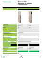
The range of NIM network interface modules comprises 4 basic NIM modules and 7
standard NIM modules.
Each module is dedicated to a specific network or bus:
Network or bus
Ethernet network
CANopen bus
Modbus Plus™ network
Fipio® bus
InterBus® bus
Profibus DP™ bus
DeviceNet™ network
Basic network interface
module
–
STB NCO 1010
–
–
STB NIB 1010
STB NDP 1010
STB NDN 1010
Standard network interface
module
STB NIP 2212
STB NCO 2212
STB NMP 2212
STB NFP 2212
STB NIB 2212
STB NDP 2212
STB NDN 2212
STB Npp pppp references include a power supply connector of each type: one
screw-type connector and one spring-type connector.
Power supply for network interface modules
Network interface modules are powered by an external 24 V c power supply.
This voltage is converted to 5 V c to provide logic power to the I/O modules of the
main Modicon® STB segment.
This built-in 5V logic power supply provides a maximum current of 1.2 A.
For operations in extended temperature ranges, see page 22.
This current can be increased in each segment of an STB CPS 2111 auxiliary power
supply that also provides a maximum current of 1.2 A. For operations in extended
temperature ranges, see page 26.
The STB CPS 2111 should be associated with an STB PDT p10p power supply
module.
Logic power for the I/O modules in each extension segment is provided by the BOS
bus extension module STB XBE 1300 placed at the beginning of these segments.
See page 26.
20
Modicon® STB
distributed I/O solution
Description
Network interface modules
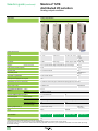
Description
Network interface modules STB Npp 2212/1010
The front panel of the STB Npp 2212/1010 network interface modules has the
following features:
4
1
5
6
2
7
3
STB Npp 2212)
standard module
only)
8
Interface modules with network/bus
address selectors
1 A connector to connect the station to the fieldbus. See photos of different
connector types on pages 18 and 19 and specifications on page 23.
2 - All NIM modules except InterBus® network interface modules: Two rotary node
addressing selectors on the bus or the network
- InterBus® STB NIB 2212/1010 network interface modules: One 9-way female
SUB-D connector to connect the outgoing bus cable
3 An external 24 V c power supply connector for the removable screw-type
(STB XTS 1120) or spring-type (STB XTS 2120) terminals. External Phaseo®
power supplies. See page 6.
4 An LED display block indicating the different states of the station on the bus:
power, communication, send/receive data, detected errors, etc.
Indication
Basic NIM modules
Standard NIM modules
Station status: auto-configuration,
operational, detected error, etc. (1)
Power supply: NIM powered up,
internal 5 V operational
Module detected error (2)
Green RUN LED
Green RUN LED
Green PWR LED
Green PWR LED
Red ERR LED
Red ERR LED
1 to 3 LED status indicators
Depending on bus/
network
–
Depending on bus/
network
Yellow Test LED
Test mode (3)
1
4
5
6
2
7
3
8
InterBus® STB NIB 2212/1010
interface modules
(STB Npp 2212
standard
module only)
5 A color-coded identification stripe: yellow
6 A screw for releasing the STB Npp 2212/1010 module from the DIN rail.
The NIM module can be removed from the station even if the product is
assembled. Simply remove the PDM and then turn this screw a quarter turn.
7 A slot for a removable SIM card STB XMP 4440 (only on STB Npp 2212 standard
NIM modules)
8 Standard NIM module: Access flap for the Reset button (4) and the port used to
connect a station setup and configuration PC or HMI terminal (read/write data).
Can also be used to update the firmware for the network interface module (5).
Basic NIM module: Access flap for the Reset button (4) and the port used to
connect a PC used only for updating the firmware of the network interface
module.
The network interface modules are supplied with:
b An English language mini CD-ROM that contains supporting documentation, a
label template and one exchange file per network type
b An STB XMP 1100 bus terminator that is mounted directly on the DIN rail.
The STB SUS 8800 CD-ROM contains specific documentation for each of the 11
network interface modules in 5 languages. These documents can also be
downloaded from www.schneider-electric.us.
(1)RUN is on permanently if the module is operational and flashes in various ways in the other states.
If RUN flashes on startup, the NIM module is in the auto-configuration phase.
If RUN flashes for a long time, there is a detected fault on the station. For information about
status indications for the NIM module and the station, refer to the “Network interface module
applications guide" for the specific network, included on the STB SUS 8800 CD-ROM or
available on our web site: www.schneider-electric.us.
(2)ERR is off when the station is OK. Otherwise, ERR flashes or is lit.
(3)Test LED off: station OK. Test LED on: backup of parameters to internal memory or SIM card
in progress. Test LED flashing: station in Test mode.
(4)Pressing the Reset button for 4 seconds restores the station to the factory configuration or the
configuration contained on the SIM card.
(5)Firmware update of NIM modules available at www.schneider-electric.us.
21
Modicon® STB
distributed I/O solution
Specifications
Network interface modules
Specifications
Network interface module type
Range
Network or bus
STB
Compliance with bus or network standards
NIP 2212
Standard
Ethernet
NCO 2212
Standard
CANopen
IEEE 802.3
CIA DS-301
NCO 1010
Basic
NMP 2212
Standard
Modbus
Plus™network
modbus.org
NFP 2212
Standard
Fipio® bus
EN 50170, Vol 3, Parts 1-3,
2-3, 3-3, 5-3, 6-3 and 7-3
Supply voltage
Operating temperature, horizontal mounting
Vc
°C (°F)
24 V non-isolated (1)
-25 to 70 (-13 to 158) (2)
Input current
Voltage range
Output voltage to the station logic bus
Nominal output current
Isolation
Immunity to electromagnetic interference (EMC)
mA
Vc
c
A
700
700
400
700
19.2 to 30 (2)
5.25 V ± 0.21%
1.2 (0.575 for STB Npp 2212 standard modules operating in the range 60 to 70°C)
None
Yes, according to IEC 61131-2
Connector type
Maximum number of
addressable I/O modules
Number of segments
supported
0 to 60
(32 to 140)
-25 to 70 (-13 to 158) (2)
To bus or network
RJ45 female 9-way male SUB-D
RS 232 port (configuration,
dialog with XBT and firmware
update)
Per station
HE 13,
8-way
female
32
HE 13,
8-way
female
32
(3)
9-way
9-way male SUB-D
female
SUB-D
HE 13, 8-way female
12
32
Primary
Extension
1
6 max.
6 max.
–
6 max.
NIB 1010
Basic
NDP 2212
NDP 1010
Standard
Basic
Profibus DP™
NDN 2212
Standard
DeviceNet™
InterBus Club
DIN 19245, Parts 1 and 3
Open DeviceNet Vendors
Association
-25 to 70
(-13 to 158)
(2)
-25 to 70
(-13 to 158)
(2)
STB network interface module type
Range
Network or bus
STB
Compliance with bus or network standards
NIB 2212
Standard
InterBus®
NDN 1010
Basic
Supply voltage
Operating temperature, horizontal mounting
Vc
°C (°F)
24 V non-isolated (1)
-25 to 70
0 to 60
(-13 to 158) (32 to 140)
(2)
Input current
Voltage range
Output voltage to the station logic bus
Nominal output current
mA
Vc
c
A
700
400
700
400
700
19.2 to 30 (2)
5.25 V ± 0.21%
1.2 (0.575 for STB Npp 2212 standard modules operating in the range
60 to 70°C [148 to 158°F])
400
Output impedance
mW
y 50
RS 232 port (configuration,
dialog with XBT and firmware
update)
Per station
< 50 up to
y 50
< 50 up to
y 50
100 kHz
100 kHz
None
Yes, according to IEC 61131-2
Incoming: 9-way male
9-way female SUB-D
SUB-D
Outgoing: 9-way female
SUB-D
HE 13,
(3)
HE 13,
(3)
8‑way
8‑way
female
female
32
12
32
12
HE 13,
8‑way
female
32
12
Primary
Extension
1
6 max.
6 max.
–
Isolation
Immunity to electromagnetic interference (EMC)
Connector type
To bus or network
Maximum number of
addressable I/O modules
Number of segments
supported
–
6 max.
0 to 60
(32 to 140)
–
< 50 up to
100 kHz
0 to 60
(32 to 140)
5-way male connector
(3)
(1)Use a 24 V c SELV (Safety Extra Low Voltage) external power supply.
(2)STB Npp 2212 standard modules:
- range -25 to 0°C (-13 to 32°F): the power supply voltage range is c 20.4 to 30 V.
- range 0 to 60°C (32 to 148°F): the power supply voltage range is c 19.2 to 30 V.
- range 60 to 70°C (148 to 158°F): the power supply voltage range is c 19.2 to 26.5 V.
(3) Connection for updating firmware only.
22
Modicon® STB
distributed I/O solution
References
Network interface modules
Network interface modules (1)
Network or bus
Range
Supply voltage
Reference
Ethernet network
Standard
24 V c
STB NIP 2212
CANopen bus
Standard
24 V c
STB NCO 2212
0.135
Basic
24 V c
STB NCO 1010
0.135
Modbus Plus™ network
Standard
24 V c
STB NMP 2212
0.145
Fipio® bus
Standard
24 V c
STB NFP 2212
0.145
InterBus® bus
Standard
24 V c
STB NIB 2212
0.155
Basic
24 V c
STB NIB 1010
0.155
Standard
24 V c
STB NDP 2212
0.140
Basic
24 V c
STB NDP 1010
0.140
Standard
24 V c
STB NDN 2212 (2)
0.140
Basic
24 V c
STB NDN 1010 (2)
0.140
Profibus DP™ bus
STB NIP 2212
STB NCO 2212/1010
DeviceNet™ network
Weight
kg
0.130
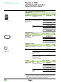
Separate parts
Description
DeviceNet removable
terminals
5-way
Type
Reference
Screw-type
STB XTS 1111
Weight
kg
–
Spring-type
STB XTS 2111
–
Replacement and optional parts
Description
Removable terminals for
24 V c
2-way
Description
STB NMP 2212
STB NFP 2212
Reference
Screw-type
10
STB XTS 1120
Weight
kg
0.003
Spring-type
10
STB XTS 2120
0.003
Use
Reference
Weight
kg
–
STB XMP 4440
External 24 V c SELV
power supply
–
See page 121
–
Configuration software (3) –
See page 101
–
Magelis® communication
terminal XBT
connection cable (3)
RS 232C shielded twisted
pair
8-way HE 13/
9-way SUB-D
(length 2 m) (3) (4)
USB SUB-D cable
See page 109
–
Bus terminator
STB NDN 2212/1010
Sold in lots of
32 KB removable SIM card Station configuration backup
(3)
User documentation
STB NIB 2212/1010
Type
Configuration PC
STB XCA 4002
0.210
Configuration PC with USB port
requires STB XCA 4002 (4)
SR2 CBL 06
0.185
Multilingual on CD-ROM (English, STB SUS 8800
French, German, Spanish and
Italian)
Also supplied with the NIM network STB XMP 1100
interface module
–
–
(1)Network interface modules are supplied with:
- A suitable power supply connector
- Documentation in English on mini CD-ROM and bus terminator (STB XMP 1100)
(2)DeviceNet 5-way removable terminals STB XTS p111, to be ordered separately
(3)Standard modules only
(4)Supplied with STB SPU 1ppp configuration software. See page 101.
23
References (continued)
Modicon® STB
distributed I/O solution
Network interface modules
Bus and network connection accessories
CANopen bus (1)
Description
TSX CAN TDM4
Fitted at ends
Length
Reference
Weight
kg
0.196
IP 20 CANopen tap 4 SUB-D ports. Screw terminals
junction
for connection of trunk cables.
Line termination.
TSX CAN TDM4
CANopen
Standard, e marking: low
0.3 m
preformed cordsets smoke emission. Halogen-free.
One 9-way female
Flame-retardant (IEC 60332-1) 1 m
SUB-D connector at
each end
3m
TSX CAN CADD03
0.091
TSX CAN CADD1
0.143
TSX CAN CADD3
0.295
5m
TSX CAN CADD5
0.440
0.3 m
TSX CAN CBDD03
0.086
1m
TSX CAN CBDD1
0.131
3m
TSX CAN CBDD3
0.268
5m
TSX CAN CBDD5
0.400
Length
Reference
Standard, UL certification,
e marking: Flame-retardant
(IEC 60332-2)
Ethernet network (1)
Description
Fitted at ends
Straight shielded
2 RJ45 connectors to connect
twisted pair cables to data terminal equipment
for connecting
(DTE)
hubs and switches
490 NTW 000 pp
2m
Weight
kg
490 NTW 000 02 (2)
–
5m
490 NTW 000 05 (2)
–
12 m
490 NTW 000 12 (2)
–
40 m
490 NTW 000 40 (2)
–
80 m
490 NTW 000 80 (2)
–
Modbus Plus network
™
Description
HAND
0
AUTO
Use
Reference
9-way male SUB-D
connector
Connection of the Modbus Plus
connector
AS MBKT 085
Modbus Plus tap
IP 20 junction box for
T-connections
990 NAD 230 00
0.230
IP 65 junction box for
T-connections, supports
one RJ45 connector on front
panel
990 NAD 230 10
0.650
IP 20 T-connector with two RJ45
connectors for Modbus Plus
cable and one 9-way SUB-D
connector for devices
connected via T-connection
170 XTS 020 00
0.260
Use
From
IP 20
170 XTS 020 00
T-connector
Reference
AS MBKT 085
Description
Modbus Plus drop
cables
Length
To
IP 20
0.25 m
170 XTS 020 00
T-connector
1m
Weight
kg
–
Weight
kg
170 MCI 020 10
–
170 MCI 020 36
–
3m
170 MCI 021 20
–
10 m
170 MCI 020 80
–
STB NMP 2212 990 NAD 230 00 2.4 m
network
tap
interface
6m
module
990 NAD 211 10
0.530
990 NAD 211 30
0.530
(1)For the complete range of CANopen and Ethernet cables and connection accessories, please
refer to the “Automation & Control. Machines & installations with industrial communications”
catalog.
(2)Cable compliant with EIA/TIA-568 Category 5 and IEC 1180/EN 50 173 Class D.
For UL- and CSA 22.1-certified cables, add letter U to end of reference.
24
References (continued)
Modicon® STB
distributed I/O solution
Network interface modules
Bus and network connection accessories (continued)
Fipio® bus
Description
Female connectors On STB NFP
(9-way SUB-D)
2212 network
interface
module
TSX FP ACC 12
Bus connection
unit
Description
TSX FP ACC 14
Use
TSX FP ACC 4
Specifications
Reference
Black poly carbonate IP 20 TSX FP ACC 12
TSX FP ACC 2
Zamak (1)
Trunk cable tap Black poly carbonate IP 20 TSX FP ACC 14
link
Zamak IP 65 (1)
TSX FP ACC 4
Weight
kg
0.040
0.080
0.120
0.660
Use
Length
Reference
8 mm, 2 shielded twisted pairs
150 W
For standard environments
100 m
TSX FP CC 100
Weight
kg
5.680
200 m
TSX FP CC 200
10.920
500 m
TSX FP CC 500
30.000
100 m
TSX FP CA 100
5.680
200 m
TSX FP CA 200
10.920
500 m
TSX FP CA 500
30.000
Use
Length
Reference
Installation remote Pre assembled cables to
bus cables
connect 2 network interface
modules
0.110 m
170 MCI 007 00
Weight
kg
–
1m
170 MCI 100 00
–
Branch interface
–
170 BNO 671 00
–
100 m
TSX IBS CA 100
–
400 m
TSX IBS CA 400
–
Use
Length
Reference
Line terminator
–
490 NAD 911 03
Weight
kg
–
Intermediate connection
–
490 NAD 911 04
–
Intermediate connection with
terminal port
–
490 NAD 911 05
–
–
100 m
TSX PBS CA 100
–
400 m
TSX PBS CA 400
–
Drop cables
Daisy chain cables 8 mm, 2 shielded twisted pairs
150 W
For standard environments
InterBus® bus
Description
Remote bus to installation
remote bus branch connection
Remote bus cables –
Profibus DP™ bus
Description
Connectors for
STB NDP 2212
network interface
module
Profibus DP
connection cables
DeviceNet™ network
Description
Use
Type
Female connectors For
Screw-type
(5-way)
STB NDN 2212
network
Spring-type
interface
module
Reference
STB XTS 1111
Weight
kg
–
STB XTS 2111
–
(1)Do not use for applications involving vibrations u 1 g or heavy impacts.
25
Specifications,
references
Modicon® STB
distributed I/O solution
Internal bus extension modules
Specifications, auxiliary and bus extension power supplies
Type of module
Power supply
V
Operating temperature,
horizontal mounting
Current consumption on 5 V c logic bus
Connectors
Power supply
°C (°F)
mA
Interface
Input current
Voltage range
Output voltage
Output current
Isolation
Immunity to electromagnetic disturbance (EMC)
mA
V
V
A
24 V c/5 V c
auxiliary power
supply
EOS internal
bus extension
BOS internal
bus extension
Bus extension to
external CANopen
devices
STB CPS 2111
24 c
not isolated
-25 to 70
(-13 to 158) (1)
–
2 removable pins
STB XBE 1100
–
STB XBE 2100
–
-25 to 70
(-13 to 158)
25
–
STB XBE 1300
24 c
not isolated
-25 to 70
(-13 to 158) (1)
–
2 removable pins
0 to 60
(32 to 140)
100
–
–
Firewire
Firewire
5 removable pins
400
19.2 to 30 c (1)
5.25 c ± 0.21%
1.2 at 5 V c (2)
–
–
–
–
400
–
19.2 to 30 c (1)
–
5.25 c ± 0.21%
–
1.2 at 5 V c (2)
–
No
Yes
according to IEC 61131-2
The STB CPS 2111 should be associated with an STB PDT p10p power supply
module.
References
Description
Use with standard STB
Reference
Weight
kg
–
EOS internal bus
extension module
Installed at the end of the
STB XBE 1100 (3)
segment (except for the last
segment on the station)
BOS internal bus
extension module
Installed at the beginning of STB XBE 1300 (4)
each extension segment
–
Bus extension module to
external CANopen devices
Installed at the end of the last STB XBE 2100
segment to connect standard
CANopen devices
–
Auxiliary power supply
STB XBE 1100
STB XBE 1300
Description
24 V c/5 V c 1.2 A
auxiliary power supply (5)
Content
Reference
screw-type and
spring-type
STB CPS 2111 K
Module only
STB CPS 2111
Weight
kg
–
(1)STB CPS 2111 and STB XBE 1300 modules:
- range -25 to 0°C (-13 to 32°F): the power supply voltage range is c 20.4 to 30 V.
- range 0 to 60°C (32 to 148°F): the power supply voltage range is c 19.2 to 30 V.
- range 60 to 70°C (148 to 158°F): the power supply voltage range is c 19.2 to 26.5 V.
(2)900 mA for operating temperatures in the range 60 to 70°C.
(3)Replaces EOS extension module STB XBE 1000.
(4)Replaces BOS extension module STB XBE 1200.
(5)Power supply for the I/O module logic, in addition to the 5 V c 1.2 A power supplies
integrated in the NIM network interface module and the BOS bus extension module.
Installed in the primary segment or the extension segments.
STB XBE 2100
26
STB CPS 2111
–
References (continued),
connections
Modicon® STB
distributed I/O solution
Internal bus extension modules
Bus extensions: mandatory separate parts
Description
Module bases
(width 18.4 mm)
Description
Used for
Reference
STB XBE 1100
STB XBE 1300
STB XBE 2100
STB CPS 2111
STB XBA 2400
STB XBA 2300
STB XBA 2000
STB XBA 2100
Type
Reference
2-way removable STB XBE 1200
terminals for
24 V c supply
(1)
Screw-type
Spring-type
Sold in
lots of
10
10
5-way
removable
terminals (1)
Screw-type
Spring-type
20
20
STB XBE 2100
Description
STB XBA 2p00
Used for
Station bus extension cables
Weight
kg
0.028
0.033
0.028
0.033
STB XTS 1120
STB XTS 2120
Weight
kg
–
–
STB XTS 1110
STB XTS 2110
0.006
0.006
Length
Reference
0.3 m
1.0 m
4.5 m
10.0 m
14.0 m
STB XCA 1001
STB XCA 1002
STB XCA 1003
STB XCA 1004
STB XCA 1006
Weight
kg
–
–
–
–
–
Bus extensions: optional separate parts
Description
Keying pin
Usercustomizable
labels (2)
Used
for
Modules
Removable
terminals
Type
–
–
I/O modules and –
bases
2.5 mm insulated Removable screw Chrome
screwdriver
terminals
vanadium
steel
Reference
60
96
STB XMP 7700
STB XMP 7800
Weight
kg
–
–
25 sheets
STB XMP 6700
–
–
STB XTT 0220
–
CANopen extension connection
STB XBE 2100: schematic connection diagram (3)
The CANopen interface fieldbus is located on the front of the STB XBE 2100
extension module.
The pinout should be as indicated in the table below:
1
2
3
4
5
Pin
1
2
3
4
5
Signal
CAN earth ground (0 V)
CAN low bus signal
Optional CAN shielding
CAN high bus signal
No connection (4)
(1)The STB XTS pppp connectors can accommodate a flexible wire with a maximum
cross-section of 1.5 mm2, including the cable end. Max. tightening torque = 0.25 Nm for
screw-type connectors.
(2)Template for user-customizable labels:
- Supplied with the documentation mini-CD-ROM provided with the NIM network interface
modules
- Available on www.schneider-electric.us.
(3)Observe the recommendations in the “Modicon STB System Hardware Components
Reference Guide”, included on the STB SUS 8800 CD-ROM and available on
www.schneider-electric.us.
(4)This spare pin can be used to distribute the 24 V of external devices.
27
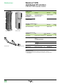
Introduction
Modicon® STB
distributed I/O solution
Power distribution modules
Introduction
Basic power distribution modules (PDM) (STB PDT p105) provide power for the I/O
module sensors and actuators (1) via the same bus 3. See page 29.
Two basic PDMs are available:
b The STB PDT 3105 module is dedicated to providing power to the I/O module sensors
and actuators requiring a 24 V c power supply.
b The STB PDT 2105 module is dedicated to providing power to the I/O module sensors
and actuators requiring a 115/230 V a power supply.
Each module has 1 removable fuse.
Standard power distribution modules (STB PDT p100) provide power separately for
the I/O module sensors and actuators (1) via the sensor bus 1 and the actuator
bus 2. See page 29.
Two standard PDMs are available:
b The STB PDT 3100 module is dedicated to providing power separately to the I/O
module sensors and actuators requiring a 24 V c power supply.
b The STB PDT 2100 module is dedicated to providing power separately to the I/O
module sensors and actuators requiring a 115/230 V a power supply.
Each module has 2 removable fuses.
(1)One power distribution module can supply power to both digital and analog I/O modules
simultaneously.
28
Introduction (continued)
Modicon® STB
distributed I/O solution
Power distribution modules
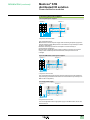
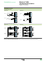
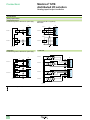
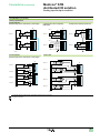
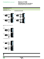
Connecting the power supplies
Three separate power supplies
115/230 V a
115/230 V a
1
1
IN
IN
2
OUT
2
OUT
24 V c
115/230 V a
Configuration with standard PDM
This configuration allows:
b Disconnection of the I/O power supply while maintaining the power supply to the
network interface module (NIM) and thus to the machine bus (for example, in a NIM
InterBus® configuration).
b Isolation of the output power from the inputs to increase immunity to
electromagnetic interference.
b Power supply independent of the outputs, enabling connection of a Preventa™
safety module. If these outputs are disconnected, the inputs continue to be
managed.
Separate NIM module and I/O power supplies
115/230 V a
115/230 V a
3
3
IN/OUT
IN/OUT
24 V c
Configuration with basic PDM
This configuration allows disconnection of the I/O power supply while maintaining
the power supply to the NIM module and thus to the machine bus (for example, in a
NIM InterBus configuration).
One single power supply
115/230 V a
115/230 V a
3
3
IN/OUT
IN/OUT
24 V c
Configuration with basic PDM
Low-cost configuration with a single power supply for the NIM module, sensor bus,
and actuator bus.
29
Modicon® STB
distributed I/O solution
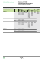
Introduction (continued)
Power distribution modules
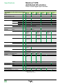
Choice of PDM based on I/O modules
Power distribution module
Voltage
STB I/O modules
Digital (discrete)
Inputs
Outputs
Solid state
DDI 3230
DDO 3200
DDI 3420
DDO 3230
DDI 3610
DDO 3410
DDI 3425
DDO 3600
DDI 3615
DDO 3415
DDI 3725
DDO 3605
DDO 3705
STB PDT 3100
24 V c
STB PDT 2100
115 V a
DAI 5230
DAI 5260
DAO 8210
DAO 5260
230 V a
DAI 7220
STB PDT 3105
24 V c
STB PDT 2105
Analog
Inputs
Relay
DRC 3210
DRA 3290
Outputs
AVI 1255
AVI 1275
AVI 1270
AVI 0300
AVI 1400
ACI 1225
ACI 1230
ACI 0320
ACI 8320
ACI 1400
ART 0200
AVO 1255
AVO 1265
AVO 1250
AVO 0200
AVO 0120
ACO 1225
ACO 1210
ACO 0220
EPI 1145
EPI 2145
EHC 3020
–
–
–
–
DAO 8210
–
–
–
–
DDI 3230
DDI 3420
DDI 3610
DDI 3425
DDI 3615
DDO 3200
DDO 3230
DDO 3410
DDO 3600
DDO 3415
DDO 3605
DRC 3210
DRA 3290
AVI 1255
AVI 1275
AVI 1270
AVI 0300
AVI 1400
ACI 1225
ACI 1230
ACI 0320
ACI 8320
ACI 1400
ART 0200
AVO 1255
AVO 1265
AVO 1250
AVO 0200
AVO 0120
ACO 1225
ACO 1210
ACO 0220
EPI 1145
EPI 2145
EHC 3020
115 V a
DAI 5230
DAI 5260
DAO 8210
DAO 5260
–
–
–
–
230 V a
DAI 7220
DAO 8210
–
–
–
–
(1) STB bus extension modules can be connected to any PDM.
30
App.
specific
STB bus
extension
modules
(1)
XBE 1100
XBE 1300
XBE 2100
XBE 1000
XBE 1200
Modicon® STB
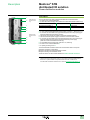
distributed I/O solution
Description
Power distribution modules
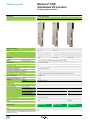
Description
7
2
(STB PDT p100
standard module
only)
1
3
4
5
6
8
(STB PDT p100
standard module
only)
The front panel of the STB PDT p10p power distribution modules features:
1 A slot for a user-customizable label
2 A status block with 2 display LEDs (STB PDT 2100/3100 standard modules only):
Indication
Basic PDM modules
Standard PDM modules
Sensor bus power supply (1)
Actuator bus power supply (1)
–
–
Green IN LED
Green OUT LED
3 A color-coded module identification stripe (red for 115/230 V a, blue for 24 V c)
4 A connector for removable screw-type terminals (STB XTS 1130) or spring-type
terminals (STB XTS 2130) used to connect:
v The sensor power supply for STB PDT 2100/3100 standard modules
v The sensor/actuator power supply for STB PDT 2105/3105 basic modules
5 A connector for removable screw-type terminals (STB XTS 1130) or spring-type
terminals (STB XTS 2130) used to connect the actuator power supply
(STB PDT 2100/3100 standard module only)
6 An STB XBA 2200 mounting base, width 18.4 mm, featuring:
v A slot for a user-customizable label 7
v A captive grounding screw 8
The STB SUS 8800 CD-ROM contains two documentation sets for the power
distribution modules in 5 languages:
b System Hardware Components Reference Guide
b System Planning and Installation Guide
These documents can also be downloaded from www.schneider-electric.us.
(1)IN/OUT LED on: Power supply present on digital I/O modules.
IN/OUT LED off: No external power supply or removable fuse inside the PDM has blown.
Refer to the “System Hardware Components Reference Guide” included on the
STB SUS 8800 CD-ROM or available from our web site: www.schneider-electric.us.
31
Modicon® STB
distributed I/O solution
Specifications
Power distribution modules
Power distribution modules, specifications
Module type
Range
Supply voltage
Operating temperature,
horizontal mounting
Maximum current
V
°C (°F)
STB PDT 3100
Standard
24 c (1)
STB PDT 2100
STB PDT 3105
Basic
24 c
STB PDT 2105
5 to 30°C
(41 to 86°F)
2.5 to 60°C
(36.5 to 148°F)
–
–
10 to 30°C
(50 to 86°F)
5 to 60°C
(41 to 148°F)
–
–
115/230 a
115/230 a
For inputs
A
-25 to 70
(-13 to 158) (1)
4 (3)
For outputs
A
8 (3)
For inputs/outputs
A
6 to 12 according to –
derating (3)
4 to 30°C
2.5 to 60°C
4
V
19.2 to 30 c (2) (3) 85 to 265 a (4)
19.2 to 30 c
85 to 265 a
Sensor/actuator bus voltage range
Hot swapping
-25 to 60 (-13 to 148)
No
Nominal consumption
mA
0 on 5 V c logic power supply
Reverse polarity protection
Yes, on the actuator –
bus
Built-in overcurrent protection For inputs
By a 5 A time-lag fuse (6)
For outputs
Maximum current on the grounding terminal
Yes, on the actuator –
bus
By a 10 A time-lag fuse (6)
A
By a 5 A time-lag fuse (6)
30 for 2 minutes
Voltage-detection thresholds IN/OUT LED on
u 15 V ± 1 V c
> 70 V ± 5 V a
–
IN/OUT LED off
< 15 V ± 1 V c
< 50 V ± 5 V a
–
Mounting base (included in kits)
STB XBA 2200 width 18.4 mm
(1)Use 24 V c safety extra low voltage (SELV) external power supplies.
(2)STB PDT 3100 module only:
- range -25 to 0°C (-13 to 32°F): the power supply voltage range is c 20.4 to 30 V.
- range 0 to 60°C (32 to 148°F): the power supply voltage range is c 19.2 to 30 V.
- range 60 to 70°C (148 to 158°F): the power supply voltage range is c 19.2 to 26.5 V.
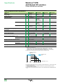
(3)Take into account the total input and output currents: combined current.
Maximum combined
current (A)
12
STB PDT 3100
only
10
8
6
Temperature: °C (°F)
-25
(-13)
0
(32)
30
(86)
45
(113)
70
60
(148) (158)
(4)DC power supplies can be shared or separate, or shared with the 24 V c power supply of the
network interface module.
(5)AC power supplies for a given distribution module from a 3-phase transformer must be
connected at the same phase.
(6)Built-in fuse on the power distribution module. Can be replaced with the STB XMP 5600 fuse
kit.
32
Modicon® STB
distributed I/O solution
References
Power distribution modules
References
The STB PDTp10pK reference kit includes: screw-type connectors, spring-type
connectors and mounting base.
Power distribution modules: connector kits
Power supply type Voltage
Type
Reference
c
24 V
Standard
Basic
STB PDT 3100 K
STB PDT 3105 K
Weight
kg
0.130
0.130
a
115/230 V
Standard
Basic
STB PDT 2100 K
STB PDT 2105 K
0.129
0.129
Power distribution modules: modules only
Power supply type Voltage
STB XBA 2200
c
24 V
Standard
Basic
STB PDT 3100
STB PDT 3105
Weight
kg
0.130
0.130
a
115/230 V
Standard
Basic
STB PDT 2100
STB PDT 2105
0.129
0.129
STB PDT 3100
Type
Reference
Replacement and optional parts
Description
Mounting base
(width 18.4 mm)
STB XTS 1130
STB XSP 3000
Sold Reference
in lots
of
Mounting of STB PDT p10p power 1
STB XBA 2200
distribution modules on DIN rails
Removable
terminals (2-pin)
(1)
Screw-type
Spring-type
Keying pins
Weight
kg
0.035
STB XTS 1130
STB XTS 2130
0.006
0.006
Keying between the power
–
distribution module and its base
(sold in lots of 60)
Keying between the power
–
distribution module and removable
terminals (sold in lots of 24) (2)
STB XMP 7700
–
STB XMP 7810
–
User-customizable
label sheets (3)
Bases and modules
STB XMP 6700
–
Grounding kit
Grounding for shielded cables. Kit 1
comprises 1 bar (1 m) and 2 lateral
supports
STB XSP 3000
–
Terminals for
grounding kit
Cables with a cross-section of
1.5 to 6 mm2
10
STB XSP 3010
–
Cables with a cross-section of
5 to 11 mm2
Screw-type removable terminals
10
STB XSP 3020
–
–
STB XTT 0220
–
STB XTS 2130
STB XSP 3010/3020
Used for
Insulated
screwdriver, 2.5 mm
10
10
25
Phaseo® regulator supplies - single phase switching
Output voltage
24 V c
Line input
voltage 47 to
63 Hz
100 to 240 V
Nominal
power
Nominal
current
48 to 240 W 2 to 10 A
Reference
Weight
kg
See page 121
–
Replacement parts
Designation
Fuses
Description
Reference
5 A (lot of 5)
and 10 A (lot of 5)
STB XMP 5600
Weight
kg
–
(1)All STB XTS pppp connectors can accommodate a flexible wire with a maximum crosssection of 1.5 mm2, including the cable end. For screw-type connectors, the maximum tightening
torque is 0.25 Nm.
(2)Supplied with STB XTS 1130/2130 removable terminals.
(3) The template for the user-customizable labels is supplied on the documentation miniCD‑ROM.
33
Selection guide
Modicon® STB
distributed I/O solution
Digital I/O modules
Applications
Digital (discrete) input modules
Direct current
Voltage
24 V c
Number of channels
2
4
Sensor type
2 or 3-wire + earth ground
2 or 3-wire
Default logic
Configurable logic
Type (IEC/EN 61131-2)
Internal power supply for
3-wire sensors
Positive
Yes (1)
Type 2
Yes (2 outputs)
No
Type 1+
Yes (4 outputs)
Yes (1)
Off-to-on
610 ms at 0.2 ms input filter
time
625 ms at 0.2 ms input filter
time
3.5 ms
925 ms at 0.5 ms input filter
time
1.35 ms at 0.5 ms input filter
time
Filter time
0.2...16 ms
3 ms
Connection (connectors included in kits)
Two connectors (6-way):
STB XTS 1100 (screw-type) or STB XTS 2100 (spring-type)
Base (included in kits)
STB XBA 1000
Inputs
Response time
On-to-off
3.8 ms
0.5...16 ms
Power Distribution Modules
(PDM) (2)
Voltage
Reference
24 V c
STB PDT 3100/3105
Isolation
Channel-to-bus
Channel-to-channel
1500 V c for 1 minute
–
Protection against
Reverse polarity
Short circuit and overload
Electronic protection of
sensor power supply
Yes
Yes, time-lag fuse on the Power Distribution Module (PDM)
Yes
No
Yes
Operating temperature (3)
-25 to 70°C (-13 to 158°F)
0 to 60°C (32 to 148°F)
-25 to 70°C (-13 to 158°F)
Module range
Standard
Basic
Standard
Type of module
STB DDI 3230 K
STB DDI 3425 K
STB DDI 3420 K
Page
48
(1)Adjustable with STB SPU 1ppp configuration software.
(2)One Power Distribution Module (PDM) is required per voltage type.
(3) Horizontal mounting.
34
0
Digital (discrete) input modules
Direct current
24 V c
6
16
2-wire
2 or 3-wire
Positive
No
Type 1
Non
Yes (1)
No
Type 3
Yes (4 outputs)
5.25 ms
1.21 ms
2 ms
5.75 ms
1.74 ms
2 ms
5 ms
1 ms
Two connectors (6-way):
STB XTS 1100 (screw-type) or STB XTS 2100 (spring-type)
Two connectors (18-way):
STB XTS 1180 (screw-type) or STB XTS 2180 (spring-type)
STB XBA 1000
STB XBA 3000
24 V c
STB PDT 3100/3105
1500 V c for 1 minute
–
Yes
Yes, time-lag fuse on the Power Distribution Module (PDM)
No
0 to 60°C (32 to 148°F)
-25 to 70°C (-13 to 158°F)
-25 to 70°C (-13 to 158°F)
Basic
Standard
Basic
STB DDI 3615 K
STB DDI 3610 K
STB DDI 3725 KS, KC
48
35
Selection guide (continued)
Modicon® STB
distributed I/O solution
Digital I/O modules
Applications
Digital (discrete) output modules
Direct current (transistor)
Voltage
24 V c
Number of channels
2
4
Positive
Yes
Yes
No
No
Yes
Outputs
Default logic
Configurable logic
Internal power supply for
3-wire actuators
Load current
Response time
0.5 A
2A
0.25 A
0.5 A
Off-to-on
620 ms at 0.5 A load
520 ms
560 ms at 0.25 A load
560 ms at 0.5 A load
On-to-off
575 ms at 0.5 A load
720 ms
870 ms at 0.25 A load
870 ms at 0.5 A load
Detected fault recovery response
User-configurable (1)
Manual reset
User-configurable (1)
Fall back modes
User-configurable (1)
Fallback to 0
User-configurable (1)
Connection (connectors included in kits)
Two connectors (6-way): STB XTS 1100 (screw-type)
or STB XTS 2100 (spring-type)
STB XBA 1000
Base (included in kits)
Power Distribution Modules
(PDM) (2)
Voltage
Reference
24 V c
STB PDT 3100/3105
Isolation
Channel-to-bus
Channel-to-channel
1500 V c for 1 minute
–
500 V c for 1 minute
–
Reverse polarity
Short circuit and overload
Electronic protection of
actuator power supply
Yes
Yes (3)
Yes
Yes (3)
No
Protection against
(4)
Yes, with internal
power supply
No
Operating temperature (5)
-25 to 70°C (-13 to 158°F) -25 to 70°C (-13 to 158°F) 0 to 60°C (32 to 148°F)
-25 to 70°C (-13 to 158°F)
Module range
Standard
Basic
Standard
Type of module
STB DDO 3200 K
STB DDO 3415 K
STB DDO 3410 K
STB DDO 3230 K
Page
48
(1)Requires the STB SPU 1ppp configuration software.
(2)One Power Distribution Module (PDM) is required per voltage type.
(3)Built-in time-lag fuses on the Power Distribution Module (PDM).
(4)If an external power supply is used, 2.5 A time-lag fuses are recommended on each channel. (Fuses are to be supplied by the user.)
(5) Horizontal mounting.
36
Digital (discrete) output modules
Direct current (transistor)
24 V c
6
16
Positive
No
No
Yes
No
No
0.25 A
0.5 A
0.5 max. per channel
550 ms at 250 mA
resistive load
900 ms at 250 mA
resistive load
715 ms at 0.5 A load
2 ms at 0.5 A load
955 ms at 0.5 A load
2 ms at 0.5 A load
Manual reset
User-configurable (1)
Manual reset
Fallback to 0
User-configurable (1)
Fallback to 0
Two connectors (6-way): STB XTS 1100
(screw-type) or STB XTS 2100 (spring-type)
STB XBA 1000
Two connectors (18-way): STB XTS 1180 (screw-type) or STB XTS 2180 (spring-type)
STB XBA 3000
24 V c
STB PDT 3100/3105
1500 V c for 1 minute
–
Yes
Yes (3)
No
0 to 60°C (32 to 148°F)
-25 to 70°C (-13 to 158°F)
-25 to 70°C (-13 to 158°F)
Basic
Standard
Basic
STB DDO 3605 K
STB DDO 3600 K
STB DDO 3705 KS, KC
48
37
Selection guide (continued)
Modicon® STB
distributed I/O solution
Digital I/O modules
Applications
Digital (discrete) input modules
Alternating current
Voltage
115 V a
Number of channels
2
Sensor type
2 or 3-wire + earth ground
Inputs
Response time
Default logic
Configurable logic
Type (IEC/EN 61131-2)
–
Yes (1)
Type 1
Internal power supply for
3-wire sensors
Yes
Off-to-on
On-to-off
1.5 line cycles
1.5 line cycles
230 V a
2-wire
Filter time
–
Connection (connectors included in kits)
Two connectors (5-way):
STB XTS 1110 (screw-type) or STB XTS 2110 (spring-type)
Base (included in kits)
STB XBA 2000
Power Distribution Modules
(PDM) (2)
Voltage
Reference
115 V a
STB PDT 2100/2105
Isolation
Channel-to-bus
Channel-to-channel
1780 V a for 1 minute
–
Reverse polarity
Short circuit and overload
Electronic protection of
sensor power supply
Yes
Yes, 5 A time-lag fuse on the Power Distribution Module (PDM)
Yes
No
Protection against
Operating temperature (3)
0 to 60°C (32 to 148°F)
Module range
Standard
Type of module
STB DAI 5230 K
Page
48
(1)Requires the STB SPU 1ppp configuration software.
(2)One Power Distribution Module (PDM) is required per voltage type.
(3) Horizontal mounting.
38
2 or 3-wire + earth ground
115 V a external supply
230 V a
1780 V a, 1 minute
–
STB DAI 5260 K
Yes
STB DAI 7220 K
Modicon® STB
distributed I/O solution
Digital I/O modules
Applications
Digital (discrete) output modules
Direct/alternating current (relay)
Alternating current (triac)
Voltage
24 V c (relay contact)
115/230 V a (relay contact)
115 V a
Number of channels
2 C/O relays
2
Outputs
Default logic
Configurable logic
Internal power supply for
3-wire actuators
Load current
Response time
Off-to-on
On-to-off
2 relays (N/C + N/O)
–
–
No
Positive
Yes (1)
Yes
115/230 V a
–
–
2 A per contact
7 A per contact
2 A at 30°C (86°F)
1 A at 60°C (148°F)
5.25 ms
6.75 ms
10 ms
10 ms
0.5 line cycles
0.5 line cycles
10 ms
10.5 ms
Automatic reset
User-configurable (1)
Detected fault recovery response
Manual reset
Fall back modes
User-configurable (1)
Connection (connectors included in kits)
Two connectors (5-way): STB XTS 1100 (screw-type) or STB XTS 2110 (spring-type)
Base (included in kits)
STB XBA 2000
STB XBA 3000
STB XBA 2000
Power Distribution Modules
(PDM) (2)
Voltage
Reference
24 V c (relay coil)
STB PDT 3100/3105
–
–
Isolation
Channel-to-bus
Channel-to-channel
1780 V a for 1 minute
500 V a for 1 minute
1780 V a for 1 minute
1780 V a for
–
1 minute
Protection against
Reverse polarity
Short circuit and overload
Electronic protection of
actuator power supply
–
Yes (3)
No
Yes
(4)
No
Operating temperature (5)
-25 to 70°C (-13 to 158°F) (6)
0 to 60°C (32 to 148°F)
Module range
Standard
Type of module
STB DRC 3210 K
STB DRA 3290 K
STB DAO 5260 K
115/230 V a
STB PDT 2100/2105
Yes (3)
STB DAO 8210 K
Page
48
(1)Requires the STB SPU 1ppp configuration software.
(2)One Power Distribution Module (PDM) is required per voltage type.
(3)Built-in time-lag fuses on the Power Distribution Module (PDM).
(4)2.5 A time-lag fuses are recommended on each channel. (Fuses are to be supplied by the user.)
(5) Horizontal mounting.
(6) With limiting between 60°C and 70°C (148 and 158°F) (see page 47).
39
Introduction,
description
Modicon® STB
distributed I/O solution
Digital I/O modules
Introduction
Modicon® STB digital input/output modules include:
b Input modules
b Solid state output modules
b Relay output modules
The basic digital I/O module offer includes:
b 3 digital input modules:
v 4, 6, and 16 x 24 V c input channels
b 3 digital output modules:
v 4, 6, and 16 x 24 V c output channels
The standard digital I/O module offer includes:
b 6 digital input modules:
v 2, 4, and 6 x 24 V c input channels
v 2 x 115 V a input channels (2 modules)
v 2 x 230 V a input channels
b 6 solid state digital output modules:
v 2 x 24 V c output channels (2 modules)
v 4 and 6 x 24 V c output channels
v 2 x 115 V a output channels
v 2 x 115/230 V a output channels
b 2 relay output modules:
v 2 relays with 1 N/C contact and 1 N/O contact
v 2 relays with 1 C/O contact
Description
1
2
3
4
The front panel of digital I/O modules include:
1 A display block providing the following indication:
Indication
Basic I/O modules
Standard I/O modules
Module status: ready,
pre‑operational, operational
Module detected error (1)
Green RDY LED
Green RDY LED
– (2)
Red ERR LED
Status of each channel
Green LEDs IN1 to IN16 or Green LEDs IN1 to IN16 or
OUT1 to OUT16 depending OUT1 to OUT16 depending
on module
on module
2 A slot for a user-customizable label STB XMP 6700
3 A color-coded module identification stripe (See color codes on page 6.)
4 Two connectors for screw- or spring-type terminals
(1)RDY is on permanently if the module is operational and flashes differently in the other states.
If ERR is on or flashing, the module is inoperative.
For information about module and channel status indication, refer to the “System Hardware
Components Reference Guide” included on the STB SUS 8800 CD-ROM or available on our
web site: www.schneider-electric.us.
(2)Basic I/O modules: A module detected error is indicated by the ERR LED on the station's
Network Interface Module (NIM).
40
Description (continued)
Modicon® STB
distributed I/O solution
Digital I/O modules
Description (continued)
Mandatory parts to be ordered separately or included in kits
I/O module bases in 3 widths depending on the module:
Module size
1
2
3
Width
13.9 mm
18.4 mm
28.1 mm
Base reference
STB XBA 1000
STB XBA 2000
STB XBA 3000
These bases have:
v A slot for a user-customizable label STB XMP 6700 (1)
v 4 locations for placing the module/base keying pins (1).
Removable terminals
Connector type
(2 connectors per
module)
Screw terminals
Spring terminals
5-way
6-way
18-way
STB XTS 1110
(pack of 20)
STB XTS 2110
(pack of 20)
STB XTS 1100
(pack of 20)
STB XTS 2100
(pack of 20)
STB XTS 1180
(pack of 2)
STB XTS 2180
(pack of 2)
These removable terminals have between 5 and 18 different ways of coding the
module/connector keying pins (1).
Optional parts to be ordered separately
Mechanical keying pins and identifiers
These devices help ensure that each I/O module, base and wiring connectors are
properly matched after dismantling or replacement.
Keying of module and
base (1)
Keying of module and
connectors (1)
Module identification
(2)
Base identification (2)
STB XMP 7700
STB XMP 7800
STB XMP 6700
STB XMP 6700
The user-customizable labels STB XMP 6700 make it much easier to recognize I/O
modules and their bases.
External cable shielding connector
This optional device allows quick and easy connection of the external cable shielding
(1).
STB XSP 3000
STB XSP 3010/3020
Connection and shielding kit
Lateral supports and metal bar, length 1 m
Cable clamp size 1 (pack of 10)
for shielded cable with external diameter 1.5 to 6 mm2
Cable clamp size 2 (pack of 10)
for shielded cable with external diameter 5 to 11 mm2
STB XSP 3000
STB XSP 3010
STB XSP 3020
Digital input modules and digital output modules (24 V c, 115/220 V a and 2 A
relay) include an optional ground connecting accessory.
For analog modules, it is advisable to use this device as it allows quick and easy
connection of the external cable shielding (1).
(1)To find out how to code the keying pins and how to use the EMC kit, refer to the System
Planning and Installation Guide included on the STB SUS 8800 CD-ROM or available on our
web site: www.schneider-electric.us.
(2)Template file for printing labels on a laser printer (color or black and white) or manual marking
with indelible felt pen: included on the mini CD-ROM supplied with each NIM network
interface module or available on our web site: www.schneider-electric.us.
41
Description (continued)
Modicon® STB
distributed I/O solution
Digital I/O modules
Digital output module operating modes
Output protection and reset following overload or short-circuit
Modicon® STB digital output module
Short-circuit and thermal
overload protection
Actuator power supply
protection
Reset
Basic modules STB DDO 3415, 3605, 3705
Internal electronic
Via PDM fuse
Standard modules STB DDO 3200, 3230
Actuator powered by the module
Internal electronic
Internal electronic
On elimination of Per group of 2
the detected
channels
fault
UserPer channel
configurable (1)
Standard modules STB DDO 3200, 3230
Actuator powered externally
Internal electronic
Via external fuse
Userconfigurable (1)
Per channel
Standard modules STB DDO 3410, 3600
Internal electronic
–
–
Standard modules STB DRC 3210, STB DRA 3290
External fuse
–
Userconfigurable (1)
Per group of 2
channels
–
Standard modules STB DAO 8210
External fuse
Via external fuse
Standard modules STB DAO 5260
External fuse
–
Userconfigurable (1)
Userconfigurable (1)
Behavior of digital output modules upon detected internal communication fault on the station or between PLC and NIM
Digital output STB module
Output fallback
Basic modules STB DDO 3415, 3605, 3705
0 (open output)
Standard modules STB DDO 3200, 3230, 3410, 3600
STB DRC 3210, STB DRA 3290
STB DAO 8210, STB DAO 5260
User-configurable (2)
(1)Reset is user-configurable: automatic on elimination of the detected fault (default factory configuration) or intentional by the PLC.
Each model is independently configurable. This operation requires the Advantys™ STB SPU 1ppp configuration software.
The tripping data is transmitted to the PLC via the NIM network interface module.
(2)Fallback is user-configurable: to 0 (default factory configuration), to 1, or to "hold last value" for warm standby and hot standby applications.
Each output channel of each module is independently configurable.
This operation requires the Advantys STB SPU 1ppp configuration software.
42
Diagnostics
–
–
Description (continued)
Modicon® STB
distributed I/O solution
Digital I/O modules
Hot swapping and cold swapping of output modules
Swapping a module
Basic digital output module
Hot swap
Basic NIM
The other I/O modules fall
back to level 0 (1)
Standard digital output module
not configured "mandatory"
Not applicable (1)
Standard digital output module
configured "mandatory"
Not applicable (1)
Cold swap
Standard NIM (3)
Any type of NIM
The other I/O modules remain I/O modules and Power
operational (2)
Distribution Modules (PDM)
can be removed from the
The other I/O modules remain station.
operational (1) (2)
The removable connectors
make it easier to do this.
Output fallback according to
configuration (2) (3)
Station in pre-operational
mode.
The inputs are no longer
updated on the network/
fieldbus.
Power Distribution Module (PDM)
Illegal
Illegal
(1)The STB SPU 1ppp configuration software cannot be connected to a basic NIM. Any basic or standard I/O module is reconfigured according to the default
factory configuration.
(2)The STB SPU 1ppp configuration software can be connected via a standard NIM. Standard I/O modules can be configured.
Basic modules are not configurable (default factory configuration only).
(3)For standard digital output modules, the fallback state is configurable:
- Fallback to level 0
- Fallback to level 1
- Fallback to predefined level of the output range for analog modules
- Hold last value
43
Modicon® STB
distributed I/O solution
Specifications
Direct current digital input modules
Specifications of DC digital input modules
Type of module
Range
Number of channels
STB
DDI 3230
Standard
2
Nominal input values Voltage
V
24 c
Type (IEC/EN 61131-2)
Input limit values
Input voltage values
Type 2
Frequency
At state 1
Voltage
Min. current
At state 0
Voltage
Max. current
Permanent voltage
Absolute maximum voltage
Typical input current (at 24 V c)
Input logic
Input response time
Swapping
DDI 3425
Basic
4
DDI 3420
Standard
Type 1+
Hz
V
mA
V
mA
V
V
–
11 to 30 c
6
2.5
-3 to +5 c
2
1.2
30 c
56 c for 1.3 ms, decaying pulse
mA
7.5
8
DDI 3615
Basic
6
DDI 3610
Standard
Type 1
Type 3
15 to 30 c
2
11 to 30 c
0.5
1.5
4.5
Default
Positive on each channel
User-configurable (1)
Positive or
–
negative,
selection by
channel
0.610 with 0.2 3.5
input filter time
Positive or
–
negative,
selection by
channel
0.925 with 0.5 5.25
input filter time
Positive or
negative,
selection by
channel
1.21
2.0
0.625 with 0.2 3.8
input filter time
1.35 with 0.5 5.75
input filter time
1.74
2.0
Off-to-on
ms
On-to-off
ms
Cold swap
Hot swap
Yes
Isolation
2000 c for
1 minute
Between channels and logic bus V
Channel-to-channel
–
Yes
Yes, depending on NIM and whether module is mandatory. See table on page 43
Protection against reverse polarity
V
Input protection
1500 c for 1 minute
–
Resistor-limited
Current supplied by the sensor
Electronic short-circuit protection (SCP)
Input filter
Default
User-configurable (1)
Tolerance
I/O base (included in kits)
Power Distribution
Voltage
Module (PDM)
Model
Power supply protection
Operating temperature,
horizontal mounting
Current consumption on 5 V c logic bus
mA
ms
ms
ms
V
°C (°F)
mA
100 per
channel
1
0.20
0.50
1
2
4
8
16
± 0.1
50 per
channel
3
–
100 per
channel
1
0.50
1
2
4
8
16
–
± 0.25
–
5
–
1
–
STB XBA 1000
24 c
STB PDT 3100/3105
Integrated time-lag fuse on the PDM module (2)
-25 to 70°C
0 to 60°C
(-13 to 158°F) (32 to 148°F)
55
45
-25 to 70°C
0 to 60°C
(-13 to 158°F) (32 to 148°F)
45
XBT XBA 3000
-25 to 70°C (-13 to 158°F)
55
(1)Requires the Advantys™ STB SPU 1ppp configuration software
(2)Basic module: 5 A fuse
Standard module: 10 A fuse
44
DDI 3725
Basic
16
100
Modicon® STB
distributed I/O solution
Specifications (continued)
Direct current digital output modules
Specifications of DC digital output modules
Type of module
Range
Number of channels
Nominal output
values
Output logic
STB
Voltage
Current per channel
Default
User-configurable (1)
Output voltage values Permanent voltage
Absolute maximum voltage
Response time
V
A
DDO 3200
Standard
2
24 c
0.5
DDO 3230
DDO 3415
Basic
4
DDO 3410
Standard
DDO 3605
Basic
6
DDO 3600
Standard
2
0.25
0.5
0.25
0.5
–
(2)
–
(2)
Positive for each channel
(2)
V
V
19.2 to 30 c
56 c for 1.3 ms,
decaying voltage pulse
–
35 c for
1.3 ms,
decaying
voltage pulse
Off-to-on
620 ms at 0.5 520 ms
A load
560 ms at
0.25 A load
560 ms at
0.5 A load
550 ms at
0.25 A load
715 ms at
0.5 A load
2 ms at
0.5 A load
On-to-off
575 ms at 0.5 720 ms
A load
870 ms at
0.25 A load
870 ms at
0.5 A load
900 ms at
0.25 A load
955 ms at
0.5 A load
2 ms at
0.5 A load
Swapping
Cold swap
Hot swap
Protection against reverse polarity
Isolation
Between channels and logic
bus
Channel-to-channel
V
Yes
Yes, depending on NIM and whether module is mandatory. See table on page 43
Yes
1500 c for 1 minute
V
–
Electronic protection of outputs against
short-circuits and thermal overloads
Feedback
Leakage current (at state 0)
mA
Maximum peak current
A
Maximum load
mF
Capacity
Inductance
Minimum load current
1500 c for
1 minute
–
Per group of 2 channels
Reset
mA
Per group of
8 channels
Per channel 2 per channel, 4 or 6 per group (2 channels per group)
Per group of
8 channels
User-configurable reset with standard output modules and tripping data transmitted to NIM
network interface module.
Automatic reset on elimination of the detected fault with basic output modules (4)
0.4 at
1 at
0.4 at 30 V c max.
30 V c max. 30 V c max.
Automatic
5 at 500 ms
10 at 500 ms 2.5 at 500 ms 5 at 500 ms
2.5 at 500 ms 5 at 500 ms
(up to 6 per
(up to 6 per
(up to 6 per (up to 6 per
(up to 6 per (up to 6 per limit per
channel
minute)
minute)
minute)
minute)
minute)
minute)
50
10
1.0 at 4 Hz
0.5 H at 4 Hz switching frequency
L = 0.5/I2 x F (5)
0.5
2
–
0.5
–
0.5
–
Fallback on detected Default state
COM fault
User-configurable (1)
Fallback to 0
Yes (6)
–
Yes (6)
–
Reset on detected
COM fault
Manual reset by user required
Yes (7)
–
Yes (7)
–
Default state
User-configurable (1)
I/O base (included in kits)
Power Distribution
Module (PDM)
DDO 3705
Basic
16
Voltage
STB XBA 1000
V
Model
Power supply protection
Operating temperature,
horizontal mounting
Current consumption on 5 V c logic bus
24 c
STB PDT 3100/3105
Integrated
(9)
time-lag fuse
on the PDM
module (8)
°C (°F)
mA
STB XBA
3000
Integrated time-lag fuse on the PDM module (8)
-25 to 70°C (-13 to 158°F)
0 to 60°C
-25 to 70°C
0 to 60°C
-25 to 70°C (-13 to 158°F)
(32 to 148°F) (-13 to 158°F) (32 to 148°F)
50
45
70
90
135
(1)Requires the Advantys™ STB SPU 1ppp configuration software
(2)Positive or negative, selection by channel
(3)With standard NIM module only
(4)For basic module STB DDO 3705: automatic reset per groups of 8 channels, 1 to 8 and 9 to 16
(5)L = load inductance (H), I = load current (A), F = switching frequency (Hz)
(6)Fallback state: hold last value, set to predefined value (0 or 1) on each channel individually
(7)Manual or automatic reset, configurable for standard output modules on a station equipped with
a standard NIM module
(8)Standard modules: 10 A fuse; basic modules: 5 A fuse
(9)2.5 A time-lag fuses recommended on each channel, supplied by the user
45
Modicon® STB
distributed I/O solution
Specifications (continued)
Alternating current digital input modules
Specifications of AC digital input modules
Type of module
Range
Number of channels
Nominal input values Voltage
STB
V
Type (IEC/EN 61131-2)
Input logic
Default
User-configurable (1)
DAI 5230
Standard
2
115 a (50/60 Hz)
Type 1
–
–
Input response time
Off-to-on
On-to-off
ms
ms
1.5 network period
1.5 network period
Input limit values
Frequency
Hz
47 to 63
Input voltage values
DAI 5260
DAI 7220
230 a (50/60 Hz)
Positive
Yes, per channel (1)
–
–
At state 1
Voltage
Min. current
V
mA
74 to 132 a
4
159 to 256 a
At state 0
Voltage
Max. current
V
mA
0 to 20 a
2
0 to 40 a
Permanent voltage
V
132 a
265 a
SFlb
V
200 a for 1 cycle
400 a for 1 cycle
Swapping
Cold swap
Hot swap
Protection against reverse polarity
Isolation
Between channels and logic bus V
Channel-to-channel
V
Input protection
Yes
Yes, depending on NIM and whether module is mandatory. See table on page 43
–
1780 a for 1 minute
–
1780 a for 1 minute
–
Resistor-limited
Metal oxide varistor-limited
Resistor-limited
Current supplied by the sensor
Electronic short-circuit protection (SCP)
Input filter
Default
User-configurable (1)
Tolerance
mA
60 max.
ms
ms
ms
–
–
–
I/O base (included in kits)
Power Distribution
Module (PDM)
Voltage
Model
Power supply protection
–
STB XBA 2000
V
A
Operating temperature, horizontal mounting
°C (°F)
Current consumption on 5 V c logic bus
mA
115/230 a
STB PDT 2100/2105
Time-lag fuse on the PDM
module (3)
External 0.5 A fuse required
Time-lag fuse on the PDM
module (3)
45
40
0 to 60°C (32 to 148°F)
40
(1)Requires the Advantys™ STB SPU 1ppp configuration software
(2)Basic NIM modules do not support hot swapping of input/output modules.
(3)Basic module: 5 A fuse
Standard module: 10 A fuse
46
Modicon® STB
distributed I/O solution
Specifications (continued)
Alternating current and relay
digital output modules
Specifications of AC and relay output modules
Type of module
Range
Number of channels
Output nominal
values
Output logic
Limit voltage
Response time
STB
Swapping
Isolation
DRA 3290
DAO 5260
2 N/C and N/O
2
Voltage
V
24 c, 115/230 a
Current per channel/contact
A
2 at 24 V c
7 at 24 V c
2 at 30°C (86°F)
2 at 230 V a
7 at 230 V a
1 at 60°C (148°F)
115 a
Default
Positive on both channels
User-configurable (2)
Positive or negative by channel
5 to 30 c, 20 to 250 a
74 to 132 a
20 to 265 a
Absolute maximum
V
–
132 a
Off-to-on
5.25 ms
10 ms
0.5 a period
300 a for 10 s
400 a for 1 cycle
10 ms
On-to-off
6.75 ms
10 ms
0.5 a period
10.5 ms
600 (resistive load)
2100 (resistive load)
–
VA
Mechanical
106 operations
–
Electrical
105 operations (resistive load at max. voltage
and current)
–
Cold swap
Hot swap
Between channels and logic bus V
Yes
Yes, depending on NIM and whether module is mandatory. See table on page 43
1780 a for 1 minute
Channel-to-channel
V
500 a for 1 minute
1780 a for 1 minute
Logic bus to actuator bus
V
1500 c for 1 minute
–
Yes, by GMOV (300 V rms, 385 V c,
400 Joules max. for 20 µs, 0.1 W max.) (1)
External 5 A fuse
required
Transient voltage by
varistance and RC
2.5 at 230 V a
2 at 115 V a
Leakage current (at state 0)
mA
–
2 at 132 V a max.
Maximum peak current per relay/channel
A
Capacitive load of 20 at t = 10 ms
Minimum load current
mA
50
30 over 1 period
20 over 2 periods
1
2 relays de-energized
Both channels to 0
Fallback on detected Default state
COM fault
User-configurable (2)
Default state
Manual: Reset by user required
User-configurable (2)
–
Coil voltage
–
5
Fallback state: hold last value or set to predefined value (0 or 1) on each channel individually
I/O base (included in kits)
Power Distribution
Module (PDM)
115/230 a
V
Output surge protection (internal)
Reset on detected
COM fault
DAO 8210
Permanent
Switching capability
Relay contact life
DRC 3210
Standard
2 C/O
STB XBA 2000
V
Manual or automatic reset
STB XBA 3000
STB XBA 2000
24 c
–
Model
STB PDT 3100/3105
STB PDT 2100/2105
Coil protection
10 A time-lag fuse on PDM module
–
-25 to 60°C (-13 to 148°F) (3)
0 to 60°C (32 to 148°F)
55
70
Operating temperature, horizontal mounting
°C (°F)
Current consumption on 5 V c logic bus
mA
55
45
(1)For greater protection, an RC circuit, a freewheel diode or a GMOV peak limiter appropriate to
the voltage should be mounted in parallel across the terminals of each actuator.
(2)Requires the Advantys™ STP SPU 1ppp configuration software.
(3) -25 to 70°C (-13 to 158°F) in the following conditions:
v Only one N/O channel at any time, to be managed by the application. Example: control of
both directions of motor travel
v Maximum load: 2 A for STB DRC 3210, 4 A for STB DRA 3290
v Maximum supply voltage 24.5 V c
47
References
Modicon® STB
distributed I/O solution
Digital I/O modules
Connection kits
References
The references for input or output modules with connection kit include the following
items:
b Suitable base for the module
b "K" references: screw-type connectors and spring-type connectors
b "KS" references: screw-type connectors
b "KC" references: spring-type connectors
Basic digital input modules: connection kits
Input voltage
24 V c
Connectors
screw-type and
spring-type
screw-type
spring-type
Number of Compliance
channels with IEC/EN
61131-2
4
Type 1+
Reference
Weight
kg
STB DDI 3425 K
0.111
6
Type 1
STB DDI 3615 K
0.112
16
Type 3
STB DDI 3725 KS
STB DDI 3725 KC
0.086
Standard digital input modules: connection kits
Input voltage
Number of Compliance
channels with IEC/EN
61131-2
2
Type 2
Reference
STB DDI 3230 K
0.110
4
Type 1+
STB DDI 3420 K
0.111
6
Type 1
STB DDI 3610 K
0.112
115 V a
2
Type 1
STB DAI 5230 K
0.120
115 V a
(external supply)
230 V a
2 (isolated) Type 1
STB DAI 5260 K
0.065
2
STB DAI 7220 K
0.122
24 V c
48
Connectors
screw-type and
spring-type
Type 1
Weight
kg
References (continued)
Modicon® STB
distributed I/O solution
Digital I/O modules
Connection kits
References (continued)
Basic digital output modules: connection kits
Output
voltage
24 V c
Connectors
Output
current
screw-type
and
spring-type
0.25 A
screw-type
spring-type
0.5 A
Number
of
channels
4
Compliance
with IEC/EN
61131-2
Yes
Reference
Weight
kg
STB DDO 3415 K
0.110
6
Yes
STB DDO 3605 K
0.114
16
Yes
STB DDO 3705 KS
STB DDO 3705 KC
0.086
Standard digital output modules: connection kits
Output
voltage
24 V c
Connectors Output
current
screw-type
and
spring-type
Compliance
with IEC/EN
61131-2
Yes
Reference
0.5 A
Number
of
channels
2
Weight
kg
STB DDO 3200 K
0.112
2A
2
Yes
STB DDO 3230 K
0.116
0.5 A
4
Yes
STB DDO 3410 K
0.110
6
Yes
STB DDO 3600 K
0.114
Standard relay output modules: connection kits
Output
voltage
Connectors Output
current
24 V c or screw-type
115/ 230 V and
a (relay) spring-type
2A
Number
of
channels
2
Compliance
with IEC/EN
61131-2
Yes
Reference
Weight
kg
STB DRC 3210 K
0.130
7A
2
Yes
STB DRA 3290 K
0.130
Standard triac output modules: connection kits
Output
voltage
115 V a
Connectors Output
current
screw-type
and spring115/ 230 V type
a
2A
Number
of
channels
2
(isolated)
2
Compliance
with IEC/EN
61131-2
Yes
Reference
Weight
kg
STB DAO 5260 K
0.067
Yes
STB DAO 8210 K
0.125
49
References (continued)
Modicon® STB
distributed I/O solution
Digital I/O modules
Modules only
References (continued)
Basic digital input modules: modules only
Input voltage
Number of
channels
24 V c
4
Compliance
with IEC/EN
61131-2
Type 1+
Reference
Weight
kg
STB DDI 3425
0.111
6
Type 1
STB DDI 3615
0.112
16
Type 3
STB DDI 3725
0.086
Standard digital input modules: modules only
Input voltage
Number of
channels
2
Compliance
with IEC/EN
61131-2
Type 2
STB DDI 3230
0.110
4
Type 1+
STB DDI 3420
0.111
6
Type 1
STB DDI 3610
0.112
115 V a
2
Type 1
STB DAI 5230
0.120
115 V a (external supply)
2 (isolated)
Type 1
STB DAI 5260
0.065
230 V a
2
Type 1
STB DAI 7220
0.122
24 V c
STB DDI 3230
Reference
Weight
kg
Basic digital output modules: modules only
Output
voltage
24 V c
Output
current
Number of
channels
0.25 A
0.5 A
4
Compliance
with IEC/EN
61131-2
Yes
Reference
Weight
kg
STB DDO 3415
0.110
6
Yes
STB DDO 3605
0.114
16
Yes
STB DDO 3705
0.086
Standard digital output modules: modules only
Output
voltage
24 V c
Output
current
Number of
channels
2
Compliance
with IEC/EN
61131-2
Yes
0.5 A
STB DDO 3200
0.112
2A
2
Yes
STB DDO 3230
0.116
0.5 A
4
Yes
STB DDO 3410
0.110
6
Yes
STB DDO 3600
0.114
STB DDO 3200
Reference
Weight
kg
Standard relay output modules: modules only
Output
voltage
24 V c or
115/230 V a
(relay)
Output current Number of
channels
2A
2
Compliance
with IEC/EN
61131-2
Yes
7A
2
Yes
Reference
Weight
kg
STB DRC 3210
0.130
STB DRA 3290
0.130
Standard triac output modules: modules only
Output
voltage
STB DRC 3210
50
STB DRA 3290
Output current Number of
channels
115 V a
2A
2 (isolated)
Compliance
with IEC/EN
61131-2
Yes
115/230 V a
2A
2
Yes
Reference
Weight
kg
STB DAO 5260
0.067
STB DAO 8210
0.125
References (continued)
Modicon® STB
distributed I/O solution
Digital I/O modules
Separate parts
References (continued)
Mandatory separate parts (1)
Description
Base width
I/O bases
13.9 mm
18.4 mm
28.1 mm
Description
STB XBA 1000
STB DDI 3230
STB XBA 1000
Weight
kg
0.024
STB XBA 2000
0.028
STB XBA 3000
0.048
STB DDI
STB DDO
STB XTS 1100
Spring-type
STB DDI
STB DDO
STB XTS 2100
0.006
Screw-type
STB DAI
STB DAO
STB DRC
STB DRA
STB DAI
STB DAO
STB DRC
STB DRA
STB XTS 1110
0.006
STB XTS 2110
0.006
Screw-type
STB DDI 3725 XBT XTS 1180
STB DDO 3705
0.047
Spring-type
STB DDI 3725 STB XTS 2180
STB DDO 3705
0.034
Description
Used for
Sold in lots of
Reference
Keying pins
Modules
60
STB XMP 7700
Weight
kg
–
Removable
terminals
96
STB XMP 7800
–
I/O bases and 25
modules
STB XMP 6700
–
6-way
5-way
STB DDO 3200
Connection
type
Screw-type
STB DAI
STB DAO
STB DRC
STB DRA
Reference
Weight
kg
0.006
Removable
terminals
Sold in lots of
20 (2)
Specifications
For I/O
modules
STB DDI
STB DDO
Spring-type
Removable
18-way
terminals
Sold in lots of 2
(2)
For I/O modules Reference
Optional separate parts
User-customizable label
sheets (3)
STB XBA 2000
STB DRC 3210
(1)Except for module/base/connector kits STB Dpp pppp K/KS/KC
(2)Connectors can accommodate a flexible wire with a maximum cross-section of 1.5 mm2,
including the cable end. For screw connectors, max. tightening torque = 0.25 Nm.
(3)The template for the user-customizable labels is supplied on the documentation
mini-CD-ROM.
STB XBA 3000
STB DRA 3290
51
Modicon® STB
distributed I/O solution
Connections
Digital I/O modules
Connections
DC digital input modules
STB DDI 3230
STB DDI 3420/3425
STB DDI 3610/3615
Sensor 1
–
+
1
2
3
4
5
6
+
IN
or
Sensor 1
–
+
Sensor 2
–
Sensor 3
–
+
Sensor 4
–
B
1
2
2
3
3
4
4
Sensor 3
5
5
6
6
Sensor 4
7
7
8
8
Sensor 6
Sensor 7
Sensor 8
Sensor 2
Sensor 3
IN
IN
9
9
10
10
11
11
12
12
13
13
14
14
15
15
16
16
17
17
18
18
+
Sensor 9
Sensor 10
Sensor 1
IN
Sensor 5
Sensor 6
-
Sensor 2
1
1
2
2
3
3
4
4
Sensor 11
Sensor 3
5
5
6
6
Sensor 12
Sensor 4
7
7
8
8
9
9
Sensor 5
10
10
11
11
Sensor 6
12
12
13
13
Sensor 13
Sensor 14
Sensor 15
Sensor 16
Sensor 7
+
-
Sensor 8
IN
14
14
15
15
16
16
17
17
18
18
(1)Group 1: Contacts 1 to 9 on connector A
Group 2: Contacts 10 to 18 on connector A
Group 3: Contacts 1 to 9 on connector B
Group 4: Contacts 10 to 18 on connector B
52
1
2
3
4
5
6
Sensor 4
B
A
1
2
3
4
5
6
B
1
2
3
4
5
6
1 three-wire sensor per input group (1)
1
Sensor 5
IN
Sensor 1
B
1
2
3
4
5
6
A
Sensor 2
IN
+
STB DDI 3725
16 two-wire sensors
Sensor 1
1
2
3
4
5
6
B
Sensor 2
A
A
A
Sensor 9
IN
+
Sensor 10
-
Sensor 11
Sensor 12
Sensor 13
Sensor 14
Sensor 15
IN
+
-
Sensor 16
Connections (continued)
Modicon® STB
distributed I/O solution
Digital I/O modules
Connections (continued)
AC digital input modules
STB DAI 5230
STB DAI 5260
A
Sensor 1
N
or
A
1
L
2
IN
1
Sensor 1
(1)
115 V
3
2
IN
N
3
4
4
5
5
B
B
1
Sensor 2
2
1
(1)
2
Sensor 2
3
115 V
3
IN
4
4
5
5
(1)Link internal to module
STB DAI 7220
A
1
L
Sensor 1
N
2
IN
3
4
5
or
B
1
Sensor 2
2
3
4
5
53
Connections (continued)
Modicon® STB
distributed I/O solution
Digital I/O modules
Connections (continued)
DC digital output modules
STB DDO 3200
STB DDO 3230
1 three-wire actuator and 1 two-wire
actuator with external 24 V c power
supply
0.5 A
A
+
Actuator 1
(1)
–
or
B
1
2
3
4
5
6
Actuator 2
–
(2)
1
2
3
4
5
6
2.5 A
Actuator 1
2 two-wire actuators powered via the
PDM module
A
+
(1)
–
or
A
1
2
3
4
5
6
Actuator 1
(2)
–
B
B
2.5 A
Actuator 2
–
(1)
1
2
3
4
5
6
1
2
3
4
5
6
Actuator 2
(2)
–
+ –
c 24 V
STB DDO 3410/3415
STB DDO 3705
A
Actuator 1
Actuator 2
–
–
1
2
3
4
5
6
B
Actuator 3
Actuator 4
1
2
3
4
5
6
–
–
Actuator 2
Actuator 1
–
Actuator 2
–
Actuator 3
Actuator 4
Actuator 5
Actuator 6
–
–
–
–
1
2
3
4
5
6
1
–
2
2
3
3
–
4
4
5
5
–
6
6
7
7
–
8
8
Actuator 4
Actuator 5
Actuator 7
A
1
Actuator 3
Actuator 6
STB DDO 3600/3605
B
A
Actuator 1
Actuator 8
9
9
10
10
–
11
11
12
12
–
13
13
14
14
–
15
15
16
16
–
17
17
18
18
B
1
2
3
4
5
6
(1)Actuator is protected by external fuse (depending on use).
(2)Actuator is protected by fuse integrated in Power Distribution Module (10 A fuse with STB PDT 3100/2100 or
5 A fuse with STB PDT 3105/2105).
54
1
2
3
4
5
6
–
–
Actuator 9
Actuator 10
Actuator 11
–
Actuator 12
–
Actuator 13
–
Actuator 14
–
–
–
Actuator 15
Actuator 16
Modicon® STB
distributed I/O solution
Connections (continued)
Digital I/O modules
Connections (continued)
AC digital output modules
STB DAO 5260
STB DAO 8210
A
0.5 A
1
Actuator 1
3
4
1
L
2
115 V
A
Actuator 1
(2)
(1)
PE
N
2
5 A 250 V
3
4
5
5
or
Actuator 2
or
B
1
115 V
4
1
5 A 250 V
2
3
B
(1)
Actuator 2
(3)
2
3
–
4
5
5
DC/AC (relay) digital output modules
STB DRC 3210
STB DRA 3290
2 A 250 V
A
7 A 250 V
1
Actuator 1
2
Actuator 2
3
2 A 250 V
2
Actuator 4
3
5
7 A 250 V
Actuator 3
N P
24 V c
115/230 V a
B
1
2
7 A 250 V
4
5
4
Actuator 2
1
2
3
7 A 250 V
B
Actuator 3
1
Actuator 1
4
5
A
Actuator 4
N P
3
4
5
24 V c
115/230 V a
(1)Link is internal to module.
(2)Actuator is protected by external fuse (depending on use).
(3)Actuator is protected by fuse integrated in Power Distribution Module (10 A fuse with STB PDT 3100/2100 or 5 A fuse with STB PDT 3105/2105).
55
Selection guide
Modicon® STB
distributed I/O solution
Analog input modules
Applications
Analog input modules
Voltage
Number of channels
2
Range
0 to 10 V
-10...+10 V
Resolution
10 bits
9 bits + sign
Isolation
Channel-to-channel
11 bits + sign
30 V c (when sensor voltage is separate from logic bus voltage)
Response time
5 ms for both channels
Acquisition period
–
Acquisition or update time
10 ms for both channels
Internal power supply for 3-wire inputs
Yes
Connection (connectors included in kits)
2 x STB XTS 1100 screw-type or STB XTS 2100 spring-type 6-way connectors
Base (included in kits)
STB XBA 1000
Power Distribution Modules
(PDM) (1)
Voltage
24 V c
Reference
STB PDT 3100/3105
Fallback states
Protection against
–
Reverse polarity
Yes
Short circuit and overload
Yes, time-lag fuse on the Power Distribution Module (PDM)
Electronic protection of
sensor power supply
Cut sensor wire detection
No
Yes
No
Yes (2)
Operating temperature (3)
0 to 60°C (32 to 148°F)
Range
Basic
Type of module
STB AVI 1255 K
Page
70
(1)One Power Distribution Module (PDM) is required per voltage group.
(2)Requires Advantys™ STB SPU 1ppp configuration software.
(3)Horizontal mounting.
56
Standard
STB AVI 1275 K
STB AVI 1270 K
4
8
1 to 5 V
0 to 5 V
0 to 10 V
-5 V to +5 V
-10 V to +10 V
15 bits + sign
30 V c (when sensor voltage is separate from logic bus voltage)
–
–
13 ms
22 ms for 8 channels
–
2 x STB XTS 1100 screw-type or STB XTS 2100 spring-type 6-way connectors
STB XBA 1000
24 V c
STB PDT 3100/3105
–
Yes
No
Yes
Yes (2)
-25 to 70°C (-13 to 158°F)
Standard
STB AVI 0300
STB AVI 1400
70
57
Selection guide (continued)
Modicon® STB
distributed I/O solution
Analog input modules
Applications
Analog input modules
Current
Number of channels
2
Range
4 to 20 mA
0...20 mA
Resolution
10 bits
12 bits
Isolation
Channel-to-channel
30 V c (when sensor voltage is separate from logic bus voltage)
Response time
5 ms for both channels
Acquisition period
–
Acquisition or update time
10 ms for both channels
Internal power supply for 3-wire inputs
Yes
Connection (connectors included in kits)
2 x STB XTS 1100 screw-type or STB XTS 2100 spring-type 6-way connectors
Base (included in kits)
STB XBA 1000
Power Distribution Modules
(PDM) (1)
Voltage
24 V c
Reference
STB PDT 3100/3105
Fallback states
Protection against
–
Reverse polarity
Yes, time-lag fuse on the Power Distribution Module (PDM)
Short circuit and overload
–
Electronic protection of
sensor power supply
Cut sensor wire detection
No
Yes
No
Yes (2)
Operating temperature (3)
0 to 60°C (32 to 148°F)
-25 to 70°C (-13 to 158°F)
Range
Basic
Standard
Type of module
STB ACI 1225 K
STB ACI 1230 K
Page
70
(1)One Power Distribution Module (PDM) is required per voltage group.
(2)Requires Advantys™ STB SPU 1ppp configuration software.
(3)Horizontal mounting.
58
Multi range
4
4 to 20 mA and 0...20 mA
4 to 20 mA, 0...20 mA and HART
protocol tolerant
8
2
4 to 20 mA and 0...20 mA
Thermocouples B, E, J, K, R, S and T
Temperature probe Pt 100, Pt 1000,
Ni 100, Ni 1000, Cu 10 ± 80 mV
30 V c (when sensor voltage is
separate from logic bus voltage)
–
–
15 bits + sign
200 V c
8 ms for 4 channels
10 ms for 4 channels
80 ms for 4 channels
85 ms for 4 channels
No
22 ms for 8 channels
–
150... 360 ms (depending on the
range)
10 ms for both channels
Yes
2 x STB XTS 1100 screw-type or STB XTS 2100 spring-type 6-way connectors
STB XBA 2000
STB XBA 1000
24 V c
STB PDT 3100/3105
–
Yes, time-lag fuse on the Power Distribution Module (PDM)
–
Yes, time-lag fuse on the Power
Distribution Module (PDM)
No
Yes (2)
Yes (4 to 20 mA only)
-25 to 70°C (-13 to 158°F)
Yes (2)
0 to 70°C (32 to 158°F)
Standard
STB ACI 0320 K
70
STB ACI 8320 K
STB ACI 1400 K
STB ART 0200 K
70
59
Selection guide (continued)
Modicon® STB
distributed I/O solution
Analog output modules
Applications
Analog output modules
Voltage
Number of channels
2
Range
0...10 V
-10 to +10 V
Resolution
10 bits
9 bits + sign
Isolation
1...5 V
0...5 V
0...10 V
-5...+5 V
-10...+10 V
11 bits + sign or 12 bits 15 bits + sign
30 V c (when actuator voltage is separate from logic bus voltage)
200 V c
Load current/channel (outputs)
5 mA
150 mA
Response time
3 ms for both channels
4 ms
Acquisition period
–
Acquisition or update time
25 ms for both channels
Adjustable up to
255 ms
8 ms
Internal power supply for 3-wire inputs
Yes
–
Connection (connectors included in kits)
2 x STB XTS 1100 screw-type or STB XTS 2100 spring-type 6-way connectors
Base (included in kits)
STB XBA 1000
Power Distribution Modules
(PDM) (1)
Channel-to-channel
0...+10 V, -10...+10 V
Voltage
24 V c
Reference
STB PDT 3100/3105
STB XBA 2000
Detected COM fault fallback positions
0 V on both channels
Protection against
Reverse polarity
Yes
Short circuit and overload
2.5 A time-lag fuses recommended on each channel. To be supplied by the user
Electronic protection of
sensor power supply
No
Operating temperature (4)
0 to 60°C (32 to 148°F)
Range
Basic
Type of module
STB AVO 1255 K
(2)
Yes
-25 to 70°C
(-13 to 158°F)
Standard
STB AVO 1265 K
STB AVO 1250 K
STB AVO 0200 K
Page
70
(1)One Power Distribution Module (PDM) is required per voltage group.
(2)Hold last value: reset to 0 V on both channels; go to a predefined value (between 0 V and full scale) on each channel.
(3)By default, reset to zero on both channels. Each channel individually adjustable: hold the value, go to a predefined value between 0 and 100% of the output range.
(4) Horizontal mounting.
60
Current
1
2
4...20 mA
0...20 mA
4...20 mA
0...20 mA
12 bits
15 bits + sign
15 bits + sign
10 bits
–
30 V c (when actuator voltage is separate from logic bus voltage)
–
12 ms
3 ms for both channels
4 ms for both channels
–
–
8 ms
25 ms for both channels
Yes
No
1 x STB XTS 1100 screw-type or
STB XTS 2100 spring-type 6-way
connector
2 x STB XTS 1100 screw-type or STB XTS 2100 spring-type 6-way connectors
STB XBA 2000
STB XBA 1000
4...20 mA
–
STB XBA 2000
24 V c
STB PDT 3100/3105
(2)
4 mA on both channels
–
Yes
(2)
(3)
Yes, time-lag fuse on the Power Distribution Module (PDM)
–
No
-25 to 70°C (-13 to 158°F)
0 to 60°C (32 to 148°F)
Standard
Basic
Standard
STB ACO 0120 K
STB ACO 1225 K
STB ACO 1210 K
-25 to 70°C (-13 to 158°F)
STB ACO 0220 K
70
61
Introduction
Modicon® STB
distributed I/O solution
Analog input/output modules
Introduction
The STB analog inputs allow the acquisition of various analog values encountered in
industrial applications.
The STB analog outputs are used to control analog-controlled actuators such as
variable speed drives, proportional control valves, etc.
The basic analog I/O module offer includes:
b 3 analog input modules:
v 2 analog voltage input channels 0 to 10 V
v 2 analog current input channels ± 10 V
v 2 analog current input channels 4...20 mA
b 3 analog output modules:
v 2 analog channels, current output 0...10 V
v 2 analog channels, current output ± 10 V
v 2 analog channels, voltage output 4...20 mA
The standard analog I/O module offer includes:
b 8 analog input modules:
v 2 analog voltage input channels ± 10 V
v 2 analog current input channels 0...20 mA
v 2 channels for thermocouple, temperature probe or voltage (mV)
v 4 analog input channels 15 bits + sign, current 4...20 mA and 0...20 mA
v 4 analog input channels 15 bits + sign, current 4...20 mA and 0...20 mA, HART
protocol tolerant
v 4 analog input channels 15 bits + sign, voltage 1..5 V, 0...5 V, 0 to 10 V, -5 V to +5
V, -10 V to +10 V
v 8 analog input channels 15 bits + sign, voltage 1..5 V, 0...5 V, 0 to 10 V, -5 V to +5
V, -10 V to +10 V
v 8 analog input channels 15 bits + sign, current 4 to 20 mA and 0 to 20 mA
b 5 analog output modules:
v 1 analog channel, current output 4 to 20 mA, 15 bits + sign
v 2 analog channels, current output 0...10 V or ± 10 V
v 2 analog channels, current output 0...20 mA
v 2 analog channels, current output 4...20 mA and 0...20 mA, 15 bits + sign
v 2 analog channels, voltage output 1..5 V, 0...5 V, 0 to 10 V, -5 V to +5 V, ‑10 V to
+10 V, 15 bits + sign
62
Modicon® STB
distributed I/O solution
Description
Analog input/output modules
Description
Analog I/O modules have the following on the front panel:
2
1 A slot for a user-customizable label
2 A display block showing the state of the module (RDY, ERR)
1
Indication
3
Module status (1)
Module detected error (2)
4
Basic analog
I/O modules
Green RDY LED
–
Standard analog
I/O modules
Green RDY LED
Red ERR LED
3 A color-coded module identification stripe (See color codes on page 6.)
4 Two connectors for screw- or spring-type terminals
The module kits comprise:
b An STB XBA 1000 mounting base, width 13.9 mm or STB XBA 2000, width
18.4 mm.
Removable terminals (6-way), screw-type STB XTS 1100 or spring-type
STB XTS 2100.
To be ordered separately:
b Grounding of the cable shielding is mandatory. The optional grounding kit
STB XSP 3000 can also be used to secure cables in installations subject to severe
vibration.
5
6
5 Optional grounding kit STB XSP 3000
6 Terminals STB XSP 3010 for cables with cross-section 1.5 to 6 mm2 or
STB XSP 3020 for cables with cross-section 5 to 11 mm2.
Optional mechanical keying pins:
v Between I/O module and I/O base: STB XMP 7700
v Between wiring connectors and I/O module: STB XMP 7800
These devices help ensure that the I/O modules, bases and wiring connectors are
properly matched after dismantling or replacement.
b User-customizable label sheets: STB XMP 7600
(1) RDY LED on: Module OK. RDY LED off: No power from PDM. RDY LED flashing: Detected
fault present.
(2)ERR LED on: Internal detected error. ERR LED off: Module OK. ERR LED flashing: Module
detected error. Refer to the “System Hardware Components Reference Guide” included on
the STB SUS 8800 CD-ROM or available on our web site: www.schneider-electric.us.
63
Modicon® STB
distributed I/O solution
Specifications
Analog input modules
Specifications of analog input modules
Type of module
Type
Number of channels
STB
Range
Resolution
Isolation
bits
Between channels and sensor
V
bus
Between channels and logic bus V
Maximum input values
Response time
Swapping
Cold swap
Hot swap
AVI 1255
Basic
2
AVI 1270
Standard
0 to 10 V
± 10 V
10
11 + sign
AVI 0300
Standard
4
8
1 to 5 V
0 to 5 V
0 to 10 V
-5 V to +5 V
-10 V to +10 V
9 + sign
15 bits + sign
30 c (sensor bus power supply separate from sensor power supply)
1500 c for 1 minute
ms
5 for both channels
–
Yes
Yes, depending on NIM and whether module is mandatory. See table on page 43
Compliance with IEC/EN 61131-2
Update time
ms
Input filter
10 for both channels
–
22 for all 8
channels
Single low‑pass filter at 25 Hz cut-off frequency
Integral linearity
Differential linearity
% of full ± 0.2
scale
Monotonic
Input impedance
W
400 K
Current supplied to sensors, per channel
Electronic short-circuit protection
Power supply impedance
mA
100
No
1 max.
kW
Yes
Absolute accuracy
± 0.5% of full scale at 25°C (77°F)
Temperature drift
± 0.01% of full scale per °C
Addressing
2 words
(1 data word per
channel)
I/O base (included in kits)
STB XBA 1000
Voltage
V
Model
Operating temperature,
horizontal mounting
Current consumption on 5 V c logic bus
4 words
(2 words per
channel)
No
± 0.75% of full scale at 25°C (77°F)
2 words (1 data word per channel)
24 c
STB PDT 3100/3105
°C (°F)
0 to 60 (32 to 148)
-25 to 70 (-13 to 158)
mA
30
90
(1)Basic NIM modules do not support hot swapping of input/output modules.
64
AVI 1400
50 V c
Data format
Power Distribution
Module (PDM)
AVI 1275
Basic
Modicon® STB
distributed I/O solution
Specifications (continued)
Analog input modules
Specifications of analog input modules (continued)
Type of module
Type
Number of channels
STB
Range
Resolution
Isolation
bits
Between channels and sensor
V
bus
Between channels and logic bus V
Maximum input values
Response time
Swapping
ACI 1225
Basic
2
ACI 1230
Standard
4 to 20 mA
0 to 20 mA (1)
10
12
ACI 0320
ACI 8320
4
8
4 to 20 mA and
0 to 20 mA
15 + sign
30 c (3)
200 c
30 c (3)
1500 c for 1 minute
1780 a for 1 minute
1500 c for
1 minute
25 mA
25 mA at 50 V c
ms
Cold swap
Hot swap
ACI1400
5 for both channels
–
Yes
Yes, depending on NIM and whether module is mandatory. See table on page 43
Data format
Compliance with IEC/EN 61131-2
Update time
ms
10 for both channels
Cut-off frequency of low-pass input filter
Hz
25
Integral linearity
Differential linearity
% of full ± 0.2
scale
Monotonic
Input impedance
W
Current supplied to sensors, per channel
mA
Electronic short-circuit protection
Power supply impedance
kW
80 for all 4
channels
22 ms for all 8
channels
± 0.05
± 0.08
–
Monotonic
y 300
250
y 250
100
25
100
No
± 0.1
10 for all 4
channels
985
Yes
No
–
Absolute accuracy
± 0.5% of full scale at 25°C (77°F)
± 0.4% at 25°C (77°F)
± 0.4% of full
scale per °C
Temperature drift
± 0.01% of full scale per °C
± 0.005% per °C
± 0.005% of full
scale per °C
Addressing
2 words
(1 word per
channel)
8 words
(2 words per channel)
16 words
(8 data words,
8 status words)
I/O base (included in kits)
STB XBA 1000
Power Distribution
Module (PDM)
Voltage
V
Model
Operating temperature,
horizontal mounting
Current consumption on 5 V c logic bus
4 words
(2 words per
channel)
STB XBA 2000
24 c
STB PDT 3100/3105
°C (°F)
mA
0 to 60
(32 to 148)
30
-25 to 70 (-13 to 158)
95
90
(1)If the STB ACI 1230 module is configured with the STB SPU 1000 software, a zero offset can
be set, e.g. 4 to 20 mA.
(2)Basic NIM modules do not support hot swapping of input/output modules.
(3)Sensor bus power supply separate from sensor power supply.
65
Modicon® STB
distributed I/O solution
Specifications (continued)
Analog input modules
Specifications of analog input modules (continued)
Type of module
Type
Number of channels
STB
Range
ART 0200
Standard
2 multi ranges in any configuration
2, 3 or 4-wire temperature probes: Pt 100, Pt 1000, Ni 100, Ni 1000 and Cu 10
B, E, J, K, R, S, T thermocouples
Voltage ± 80 mV
Resolution
Isolation
bits
Between channels and sensor
V
bus
Between channels and logic bus V
Maximum input values
Response time
–
1500 a for 1 minute
±7.5 V c
ms
See details on page 67.
Update time
ms
See details on page 67.
Cut-off frequency of low-pass input filter
Hz
25
Integral linearity
% of full See details on page 67.
scale
Swapping
Cold swap
Hot swap
Data format
Differential linearity
Input impedance
W
Current supplied to sensors, per channel
mA
–
100
Electronic short-circuit protection
Power supply impedance
kW
Absolute accuracy
See details on page 67.
Temperature drift
See details on page 67.
Addressing
2 words (2 words per channel + 1 word for cold-junction compensation)
I/O base (included in kits)
STB XBA 1000
Power Distribution
Module (PDM)
Voltage
V
Model
Operating temperature,
horizontal mounting
Current consumption on 5 V c logic bus
°C (°F)
0 to 70 (32 to 158)
mA
30
(1)If the STB ACI 1230 module is configured with the STB SPU 1000 software, a zero offset can
be set; for example, 4 to 20 mA.
(2)Basic NIM modules do not support hot swapping of input/output modules.
(3)Sensor bus power supply separate from sensor power supply.
66
Modicon® STB
distributed I/O solution
Specifications (continued)
Analog input modules
Detailed specifications of STB ART 0200 analog input module
Thermocouple range
Temperature unit
Nominal values
Resolution
B
E
J
K
R
°C (by default) or °F
130 to 1820
- 270 to 1000 - 210 to 1200 - 270 to 1370 - 50 to 1768
(266 to 3308) (-454 to 1832) (-346 to 2192) (-454 to 2498) (-58 to 3214)
0.1°C or °F
Broken wire detection
Monitored independently on each channel
°C (°F)
Conversion time
With internal cold-junction
compensation
With external cold-junction
compensation
Accuracy
With internal
at 25°C
(thermocouple
cold-junction
(77°F)
detected errors not
compensation
at 60°C
included)
(140°F)
With external
at 25°C
cold-junction
(77°F)
compensation
at 60°C
(140°F)
Temperature probe range
Type
ms
±4
± 3.6
± 4.1
± 4.4
°C (°F)
± 6.8
± 7.0
± 5.5
± 4.2
± 5.0
± 6.4
°C (°F)
± 1.75
°C (°F)
± 2.85
Ni 100
Ni 1000
Cu 10
± 6.8
Pt 100
Pt 1000
2, 3 or 4-wire (3-wire by default)
°C (by default) or °F
IEC
°C (°F)
-200 to +850 (-328 to 1562) (by default)
-60 to +180 (-76 to 356)
US/JIS
°C (°F)
-100 to +450 (-148 to 842)
–
Broken wire detection
Monitored independently on each channel
Accuracy
(temperature probe
tolerances are not
included)
-100 to +260
(-148 to 500)
4-wire
W
50 (IEC/US/JIS)
500 (IEC/US/JIS)
50
500
50
2 or 3-wire
W
20 (IEC/US/JIS)
200 (IEC/US/JIS)
20
200
20
3-wire
ms
2 or 4-wire
ms
25°C (77°F) internal
°C (°F)
340 at 50 Hz
300 at 60 Hz
200 at 50 Hz
180 at 60 Hz
±1
±1
±4
25°C (77°F) external
°C (°F)
±2
±1
±4
mV
± 80 (± 81.92)
Voltage
Range
Resolution
Increments of 0.01 mV
Conversion time
ms
Input impedance
MW
Accuracy
- 270 to 400
(-454 to 752)
± 5.1
0.1°C or °F
Conversion time
- 50 to 1726
(-50 to 3139)
°C (°F)
ms
Resolution
Max. wiring
resistance
T
230 at 50 Hz
210 at 60 Hz
400 at 50 Hz
360 at 60 Hz
± 4.6
± 4.6
Temperature unit
Nominal values
S
25°C (77°F) internal
25°C (77°F) external
170 at 50 Hz
150 at 60 Hz
10 (standard)
% of full ± 0.1
scale
% of full ± 0.15 at ambient temperature
scale
67
Modicon® STB
distributed I/O solution
Specifications (continued)
Analog output modules
Specifications of analog output modules
Type of module
Type
Number of channels
STB
Range
Resolution
Isolation
bits
Between channels and actuator V
bus
Between channels and logic bus V
AVO 1255
Basic
2
AVO 1265
0... 10 V
± 10 V
1... 5 V
0... 5 V
15 + sign
150
mA
5
Response time
ms
3
Cold swap
Hot swap
Up to 5
0... 10 V
±5V
± 10 V
200 c
4
Yes
Yes, depending on NIM and whether module is mandatory. See table on page 43
Data format
Compliance with IEC/EN 61131-2
Update time
ms
25 for both channels
Conversion time
ms
–
8
Short-circuit protection on the outputs
Yes
Integral linearity
± 0.1% of full scale, typical
Differential linearity
Monotonic
Absolute accuracy
± 0.5% of full scale at 25°C (77°F)
Temperature drift
± 0.01% of full scale per °C
Fallback states
AVO 0200
0... 10 V
± 10 V
10
9 + sign
11 + sign
or 12
30 c (actuator bus power supply separate from
actuator power supply)
1500 c for 1 minute
Output current per channel
Swapping
AVO 1250
Standard
Default
V
User-configurable (1)
± 0.05% of full scale, typical
± 0.3% of full scale at 25°C
0 V on 2 channels
–
Hold last value; assign a predefined value
Fallback mode
Predefined
User configurable
Addressing
2 output data words
2 output data words and 2 4 words (2 output data words,
non-adjacent input data
2 input status words)
bytes (module and
channel status
diagnostics)
I/O base (included in kits)
STB XBA 1000
Power Distribution
Module (PDM)
Voltage
V
Model
Operating temperature,
horizontal mounting
Current consumption on 5 V c logic bus
24 c
STB PDT 3100/3105
°C (°F)
0 to 60 (32 to 148)
-25 to 70 (-13 to 158)
mA
45
265
(1)Requires Advantys™ configuration software.
68
STB XBA 2000
Modicon® STB
distributed I/O solution
Specifications (continued)
Analog output modules
Specifications of analog output modules
Type of module
Type
Number of channels
STB
Range
ACO 1225
Basic
2
4... 20 mA
Resolution
Isolation
ACO 0120
Standard
1
bits
Between channels and logic bus V
15 + sign
10
V
500
30 c (2)
mA
3.5...20, 38
20
Response time
ms
4 plus update time
3
Cold swap
Hot swap
ACO 0220
0... 20 mA (1)
4... 20 mA and
0... 20 mA
15 + sign
12
1500 c for 1 minute
Between channels and actuator
bus
Output current per channel
Swapping
ACO 1210
Standard
200 c
–
Yes
Yes, depending on NIM and whether module is mandatory. See table on page 43
Data format
Compliance with IEC/EN 61131-2
Update time
ms
Conversion time
8 at ± 0.1% of final
value
–
Short-circuit protection on the outputs
Yes
Integral linearity
± 0.05% of full scale
Differential linearity
Monotonic
Absolute accuracy
0.3% of full scale at
± 0.5% of full scale per °C
25°C
± 0.01% of full scale per °C
Temperature drift
Fallback states
Default
V
25 for both channels
–
900 ms at ± 0.1% of final value
4 ms for both channels
–
± 0.1% of full scale, typical
Minimum output
4 mA on 2 channels
(4 mA)
Hold last value, assign –
a predefined value
Minimum output (0 mA)
Fallback mode
User configurable
User configurable
Addressing
2 words: 1 output data 2 output data words
word and 1 input
status word
I/O base (included in kits)
STB XBA 2000
User-configurable (3)
Power Distribution
Module (PDM)
Voltage
V
Model
Operating temperature,
horizontal mounting
Current consumption on 5 V c logic bus
Predefined
± 0.5% of full scale,
typical
± 0.3% at 25°C
± 0.005% of full scale
per °C
Hold last value, assign a predefined value
2 output data words
plus 1 word for
configuring the
fallback state
–
STB XBA 1000
STB XBA 2000
-25 to 70 (-13 to 158)
24 c
STB PDT 3100/3105
°C (°F)
-25 to 70 (-13 to 158)
0 to 60 (32 to 148)
mA
155
40
40
210
(1)If the STB ACI 1230 module is configured with the STB SPU 1000 software, a zero offset can
be set; for example, 4 to 20 mA.
(2)Actuator bus power supply separate from actuator power supply.
(3)Requires Advantys™ configuration software.
69
References
Modicon® STB
distributed I/O solution
Analog input/output modules
Connection kits
References
The Modicon® STB analog input or output modules are available in "K" kit version,
which includes the appropriate base for the module, two screw-type connectors and
two spring-type connectors.
Standard analog input modules: connection kits
Input signal Connectors
Number
of
channels
2
4
8
Isolation
between
channels
No
Yes
No
Resolution Reference
(bits)
11 + sign
15 + sign
15 + sign
STB AVI 1270 K
STB AVI 0300 K
STB AVI 1400 K
0.115
–
–
0...20 mA
2
No
12
STB ACI 1230 K
0.116
4...20 mA and
0...20 mA
4
Yes
15 + sign
STB ACI 0320 K
–
4...20 mA and
0...20 mA,
HART
tolerant
4
Yes
15 + sign
STB ACI 8320 K
–
Thermocouples
± 80 mV
2
No
15 + sign
STB ART 0200 K
–
± 10 V
Screw-type
and
spring-type
Weight
kg
Basic analog input modules: connection kits
Input signal Connectors
-10 to +10 V
70
Number Isolation
of
between
channels channels
Resolution Reference
(bits)
Weight
kg
Screw-type
2
and spring-type
No
9 + sign
STB AVI 1275 K
0.115
0...10 V
2
No
10
STB AVI 1255 K
0.116
4 to 20 mA
2
8
No
10
15 + sign
STB ACI 1225 K
STB ACI 1400 K
–
–
References (continued)
Modicon® STB
distributed I/O solution
Analog input/output modules
Connection kits
References (continued)
Standard analog output modules: connection kits
Output
signal
Connectors
Number of Isolation
channels between
channels
Resolution Reference
(bits)
Screw-type
and
spring-type
2
2
1
No
Yes
–
12
15 + sign
15 + sign
STB AVO 1250 K
STB AVO 0200 K
STB ACO 0120 K
0.116
–
–
0... 20 mA
2
Yes
12
STB ACO 1210 K
0.117
4...20 mA
and
0...20 mA
2
Yes
15 + sign
STB ACO 0220 K
–
0... 10 V or
± 10 V
Weight
kg
Basic analog output modules: connection kits
Output
signal
Connectors
Number of Isolation
channels between
channels
Resolution Reference
(bits)
Weight
kg
-10 to +10 V Screw-type
and
spring-type
0...10 V
2
No
9 + sign
STB AVO 1265 K
0.115
2
No
10
STB AVO 1255 K
0.116
4 to 20 mA
2
No
10
STB ACO 1225 K
–
71
References (continued)
Modicon® STB
distributed I/O solution
Analog input/output modules
Modules only
References (continued)
Standard analog input modules: modules only
Input signal
± 10 V
0...20 mA
4...20 mA and 0...20 mA
4...20 mA and 0...20 mA,
HART tolerant
Thermocouples ± 80 mV
Number of Isolation
channels between
channels
2
No
4
Yes
8
No
2
No
4
Yes
4
Yes
11 + sign
15 + sign
15 + sign
12
15 + sign
15 + sign
STB AVI 1270
STB AVI 0300
STB AVI 1400
STB ACI 1230
STB ACI 0320
STB ACI 8320
2
15 + sign
STB ART 0200
No
Resolution Reference
(bits)
Weight
kg
0.115
–
–
0.116
–
–
–
Basic analog input modules: modules only
Input signal
STB AVI 1270
-10 to +10 V
0...10 V
4 to 20 mA
Number of Isolation
channels between
channels
2
No
2
No
2
8
No
Resolution Reference
(bits)
9 + sign
10
10
15 + sign
STB AVI 1275
STB AVI 1255
STB ACI 1225
STB ACI 1400
Weight
kg
0.115
0.116
–
–
Standard analog output modules: modules only
Output signal
0... 10 V or ± 10 V
0... 20 mA
4...20 mA and 0...20 mA
Number of Isolation
channels between
channels
2
No
2
Yes
1
–
2
Yes
2
Yes
Resolution Reference
(bits)
12
15 + sign
15 + sign
12
15 + sign
STB AVO 1250
STB AVO 0200
STB ACO 0120
STB ACO 1210
STB ACO 0220
Weight
kg
0.116
–
–
0.117
–
Basic analog output modules: modules only
Output signal
STB AVO 1250
72
-10 to +10 V
0...10 V
4 to 20 mA
Number of Isolation
channels between
channels
2
No
2
No
2
No
Resolution Reference
(bits)
9 + sign
10
10
STB AVO 1265
STB AVO 1255
STB ACO 1225
Weight
kg
0.115
0.116
–
References (continued)
Modicon® STB
distributed I/O solution
Analog input/output modules
Separate parts
References (continued)
Separate parts (1)
Description
I/O base
Base width
For I/O
modules
STB AVI
STB ACI 1230/1225
STB ART
STB AVO
STB ACO
STB ACI 0320/8320
Reference
Connection
type
Screw-type
For I/O
modules
STB AVI
STB ACI
STB ART
STB AVO
STB ACO
Sold in lots of
Reference
20
STB XTS 1100
Weight
kg
0.006
Spring-type
STB AVI
STB ACI
STB ART
STB AVO
STB ACO
20
STB XTS 2100
0.006
Sold in lots of
Reference
13.9 mm
18.4 mm
Description
Removable
terminals
(6 contacts) (2)
STB XBA 1000
Description
Used for
STB XSP 3010/3020
–
STB XTT 0220
STB XSP 3000
–
10
STB XSP 3010
–
10
STB XSP 3020
–
60
STB XMP 7700
–
Removable terminals
96
STB XMP 7800
–
I/O bases and modules
25 sheets
STB XMP 6700
–
Terminals for Cables with cross-section
grounding kit 1.5...6 mm2
Cables with cross-section
5...11 mm2
Keying pins
Modules
Usercustomizable
labels (3)
STB XBA 2000
Weight
kg
–
2.5 mm
Removable screw terminals
–
insulated
screwdriver
Grounding kit Grounding for shielded cables –
Consisting of 1 bar (length 1 m)
and 2 lateral supports
STB XSP 3000
STB XBA 1000
Weight
kg
0.024
(1)Except for module/base/connector kits STB App pppp K.
(2)Connectors can accommodate a flexible wire with a maximum cross-section of 1.5 mm2,
including the cable end. For screw-type connectors, max. tightening torque: 0.25 Nm.
(3)The template for the user-customizable labels is supplied on the documentation mini
CD-ROM.
73
Modicon® STB
distributed I/O solution
Connections
Analog input/output modules
Connections
Analog input modules
STB AVI 1255/1270/1275
2 isolated analog sensors, external 24 V c power supply
2 analog sensors, 24 V c supplied by
PDM module
A
1
2
3
4
5
6
+
U
Sensor 1
–
(1)
+
U
Sensor 2
–
(1)
1
2
3
4
5
6
(1)
+
Sensor 1
U
–
0V
B
1
2
3
4
5
6
A
24 V c
B
24 V c
1
2
3
4
5
6
(1)
+
Sensor 2
U
–
0V
+ –
24 V c
STB AVI 0300
2 isolated analog sensors, external 24 V c power supply
STB AVI 1400
+
+
U
Sensor 1
U
(1)
(1)
–
(1)
+
+ –
24 V c
–
U
U
A
–
(1)
1
2
3
4
5
6
(1)
+
Sensor 2
U
U
+
(1)
–
B
1
2
3
4
5
6
+
Sensor 3
U
(1)
U
+
(1)
–
+
Sensor 4
U
U
–
+ –
24 V c
(1)STB XSP 3000 grounding kit with STB XSP 3010/3020 terminals mandatory.
74
+
B
Sensor 2
U
1
2
3
4
5
6
–
+
U
A
–
+
Sensor 1
+
1
2
3
4
5
6
Modicon® STB
distributed I/O solution
Connections (continued)
Analog input/output modules
Connections (continued)
Analog input modules
STB ACI 1225/1230
2 isolated analog sensors, external 24 V c power supply
2 analog sensors, 24 V c supplied by
PDM module
A
+
Sensor 1
I
(1)
–
+
Sensor 1
+
I
Sensor 2
–
+ –
(1)
–
+
Sensor 2
I
1
2
3
4
5
6
(1)
–
0V
+
–
1
2
3
4
5
6
(1)
I
Sensor 1
(2)
B
(2)
B
24 V c
1
2
3
4
5
6
(1)
1
2
3
4
5
6
0V
(2)
B
I
A
A
24 V c
1
2
3
4
5
6
2 analog sensors requiring a power loop
+
I
Sensor 2
(1)
–
0V
1
2
3
4
5
6
24 V c
STB ACI 0320/8320
4 isolated analog sensors, external 24 V c power supply
STB ACI 1400
+
A
+
Sensor 1
I
–
+
Sensor 2
–
I
(1)
(1)
I
Sensor 1
1
2
3
4
5
6
I
+
A
–
I
Sensor 2
I
+
(1)
–
B
+
Sensor 3
I
–
+
Sensor 4
I
+ –
–
(1)
(1)
1
2
3
4
5
6
1
2
3
4
5
6
(1)
+
B
+
I
Sensor 3
(1)
I
+
(1)
–
+
Sensor 4
I
24 V c
I
1
2
3
4
5
6
+
–
+ –
24 V c
(1)STB XSP 3000 grounding kit with STB XSP 3010/3020 terminals mandatory.
(2)Internal connection.
75
Modicon® STB
distributed I/O solution
Connections (continued)
Analog input/output modules
Connections (continued)
Analog input modules
STB ART 0200
2 and 3-wire temperature probes
2-wire temperature probes in highly
disturbed operating environments
A
Sensor 1
2-wire
A
1
2
3
4
5
6
(1)
U
(2)
Sensor 1
4-wire
U
(1)
B
Sensor 2
3-wire
U
B
1
2
3
4
5
6
(1)
(2)
Sensor 2
4-wire
U
(1)
2-wire thermocouple and voltage sensor
(mV)
Sensor 1
2-wire
thermocouple
Tc
A
1
2
3
4
5
6
+
–
(1)
B
Sensor 2
(mV)
U
1
2
3
4
5
6
(1)
4-wire temperature probes
A
Sensor 1
4-wire
U
1
2
3
4
5
6
(1)
B
Sensor 2
4-wire
U
(1)
1
2
3
4
5
6
(1)STB XSP 3000 grounding kit with STB XSP 3010/3020 terminals mandatory.
(2)Double-shielded cable.
76
1
2
3
4
5
6
1
2
3
4
5
6
Connections (continued)
Modicon® STB
distributed I/O solution
Analog input/output modules
Connections (continued)
Analog output modules
STB AVO 1255/1265/1250
2 isolated analog actuators
2 analog actuators, 24 V c supplied by the PDM
A
Actuator 1
1
2
3
4
5
6
+
U
–
(1)
Actuator 1
1
2
3
4
5
6
+
U
–
(1)
+
U
1
2
3
4
5
6
(1)
–
0V
B
Actuator 2
A
24 V
B
24 V
Actuator 2
+
U
1
2
3
4
5
6
(1)
–
0V
+ –
24 VDC
STB AVO 0200
2 non isolated analog actuators, external 24 V c power
supply
A
Actuator 1
1
2
3
4
5
6
+
U
–
(1)
2 non isolated analog actuators, external 24 V c power supply
+
U
+
U
+ –
c 24 V
–
(1)
1
2
3
4
5
6
(1)
B
Actuator 2
+
U
+ –
c 24 V
1
2
3
4
5
6
–
+ –
c 24 V
B
Actuator 2
A
Actuator 1
–
(1)
1
2
3
4
5
6
(1)STB XSP 3000 grounding kit with STB XSP 3010/3020 terminals mandatory.
77
Connections (continued)
Modicon® STB
distributed I/O solution
Analog input/output modules
Connections (continued)
Analog output modules
STB ACO 0120
1 sink actuator
Actuator 1
1 source actuator
A
+
I
–
A
Actuator 1
1
2
3
4
5
6
(1)
1
2
3
4
5
6
+
(1)
I
–
B
B
1
2
3
4
5
6
1
2
3
4
5
6
1 source actuator, external 24 V c power supply
1 sink actuator, external 24 V c power supply
A
I
+
–
A
1
2
3
4
5
6
(1)
+
c 24 V
–
Actuator 1
c 24 V
+
–
I
B
1
2
3
4
5
6
(1)
+
B
1
2
3
4
5
6
(1)STB XSP 3000 grounding kit with STB XSP 3010/3020 terminals mandatory.
78
–
Actuator 1
1
2
3
4
5
6
Modicon® STB
distributed I/O solution
Connections (continued)
Analog input/output modules
Connections (continued)
Analog output modules
STB ACO 0220
2 isolated analog actuators, external 24 V c power supply
2 analog actuators, 24 V c supplied by the PDM
A
Actuator 1
c 24 V
1
2
3
4
5
6
+
–
+
I
(1)
Actuator 1
I
A
+
–
1
2
3
4
5
6
(1)
B
Actuator 2
–
I
+
+
c 24 V
–
B
1
2
3
4
5
6
(1)
1
2
3
4
5
6
Actuator 2
I
+
–
(1)
2 analog actuators, 24 V c supplied by the PDM
A
24 V
1
2
3
4
5
6
+
Actuator 1
I
–
0V
B
24 V
1
2
3
4
5
6
+
Actuator 2
I
–
0V
STB ACO 1225/1210
2 isolated analog actuators, external 24 V c power supply
2 analog actuators, 24 V c supplied by the PDM
A
1
2
3
4
5
6
–
Actuator 1
I
24 V
(1)
+
–
B
–
Actuator 2
I
+
24 V
–
(1)
A
+
Actuator 1
I
–
1
2
3
4
5
6
(1)
B
(2)
1
2
3
4
5
6
–
Actuator 2
I
24 V
+
–
(1)
(2)
1
2
3
4
5
6
(1)STB XSP 3000 grounding kit with STB XSP 3010/3020 terminals mandatory.
(2) Internal connection.
79
Modicon® STB
distributed I/O solution
Description
Parallel interface module STB EPI 2145
TeSys® U controller and TeSys® Quickfit applications
Description
1
2
3
4
5
The STB EPI 2145 application-specific parallel interface module is a component of
the Modicon® STB station designed for the remote connection of TeSys® U startercontrollers and TeSys® Quickfit prewired motor starters.
The STB EPI 2145 application-specific parallel interface module includes:
1 An LED display block indicating the various states of the starter-controllers or
TeSys Quickfit prewired motor starters
Indication
Standard STB EPI 2145 module
Module status (1)
Module detected error (2)
Green RDY LED
Red ERR LED
Selector switch position 4 (3)
State of outputs
Green LEDs S1 and S2
Green LEDs O1/5, O2/6, O3/7, O4/8
2 Slot for a user-customizable label
3 A color-coded identification stripe (black)
4 A selector switch used to view each motor starter state
5 4 RJ45 connectors for connection of:
b 4 TeSys model U starter-controllers
b 4 direct motor starters with TeSys Quickfit components
b 2 reversing motor starters with TeSys Quickfit components; for example, 12 inputs
and 8 outputs in each of these configurations
The STB EPI 2145 K module kit comprises:
b STB XBA 3000 base, width 28.1 mm. This base includes a slot for a usercustomizable label.
To be ordered separately:
b Optional mechanical keying pins between the module and the I/O base:
STB XMP 7700. This device helps to ensure that the module and its base are
properly matched if disassembled or replaced.
b Sheets of user-customizable labels: STB XMP 7600
b RJ45 cables between the STB EPI 2145 module and each TeSys U
(1)RDY is permanently on if the module is operational. If RDY is off, the PDM is not supplying
power. If RDY is flashing, the module is not functional.
(2)If ERR is on or flashing, the module has an internal detected error.
For information about module and channel status indication, refer to the “System Hardware
Components Reference Guide” included on the STB SUS 8800 CD-ROM or available on our
web site: www.schneider-electric.us.
(3)S1: Output bank 1 (outputs 1 to 4)
S2: Output bank 2 (outputs 5 to 8)
80
Description (continued)
Modicon® STB
distributed I/O solution
Parallel interface module STB EPI 2145
TeSys® U controller and TeSys® Quickfit applications
1
2
3
4
5
5
TeSys® U starter control application
Introduction of the TeSys® U starter-controller
The TeSys® U starter-controller is a direct motor starter that performs the following
functions:
b Protection and control of single-phase or three-phase motors:
v Disconnects power
v Protects against overcurrent and short circuits
v Protects against thermal overload
v Performs power switching
b Application control:
v Provides protection alarms and application monitoring: duration of use, number of
detected faults, motor current values, etc.
v Provides a logging function
Structure of a TeSys U starter with an STB EPI 2145 module (1)
The starter-controller functions are implemented with a click-lock adjustment, thus
eliminating wiring of:
b A power base 2 (LU2B + LU9 BN11)
b A 24 V c 3 control unit (LUC B/D/C/M ppBL) for 0.09 to 15 kW motors
b A parallel communication module (LUF C00) 4
b Options (additional contacts, reverser blocks) 5, including LU9 M1p
Combined with a TeSys U starter, each of the 4 channels of the STB EPI 2145
application-specific module features:
b 2 outputs:
v Starter control
v Reversal control
b 3 inputs:
v State of circuit breaker (position of lever)
v Presence of detected faults (short circuit, thermal)
v State of main contactor (closed/open)
(1)TeSys® U components: refer to the Starters and Basic TeSys U Equipment catalog
81
Modicon® STB
distributed I/O solution
Description (continued)
Parallel interface module STB EPI 2145
TeSys® Quickfit components for motor starters
TeSys® Quickfit components for motor starters
TeSys® Quickfit is a modular system that standardizes and simplifies the
installation of motor starters.
Combined with GV2 ME circuit breakers and model d (LC1) contactors from 9 to
25 A, TeSys Quickfit facilitates the installation of motor starters with spring-type
terminals up to 11 kW/400V.
5
3
6
TeSys Quickfit offers elements for prewiring of:
b Power circuits
b Control circuits
TeSys Quickfit makes the installation of motor starters a fast, easy, reliable, and
open-ended process. It also:
b Allows for later customization of the motor starter
b Reduces maintenance time
b Saves space inside the equipment by reducing the number of terminals, cable
ducts, and intermediary interfaces
4a
4b
1
2
7
Elements for prewiring the power section
8
The TeSys Quickfit system provides the following components for prewiring the
power section:
b A power kit comprising, for each output, a mounting plate 1 for the contactor 2 and
circuit breaker 3, as well as two power connection modules, 4a and 4b
b A power splitter box 5 for 2 or 4 outputs
b An upstream terminal block 6 for connecting a power supply up to 60 A (16 mm2)
b A downstream terminal block 7 for connecting motor power supply cables and
earth ground cables (6 mm2)
Elements for prewiring the control section
For prewiring the control section, the TeSys Quickfit system provides the
LAD 9 AP3pp control connection module 8 that allows you to connect the motor
starters to the processing unit (PLC) via the Modicon STB EPI 2145 parallel interface
module 9 quickly and without the use of tools.
9
The LAD 9 AP3pp control connection module is mounted directly on the contactor
and the circuit breaker of each motor starter. It integrates the status and control
information of this motor starter.
A mechanical locking device 2 for the system on the head of the contactor helps to
ensure a correct connection regardless of the conditions of use (vibrations, shock,
etc.). Four versions are available: direct or reversing start, and with or without
contactor coil interface relay.
The lower part of the LAD9 AP3 pp module features several external connectors,
including an RJ45 socket, for connection to the Modicon STB EPI 2145 parallel
interface module via LU9Rpp RJ45 cables 10 available in different lengths.
The following information is available for each motor starter:
b 2 inputs: status of circuit breaker and status of contactor
b 1 output: contactor coil control
A direct motor starter uses 1 RJ45 channel.
A reversing motor starter uses 2 RJ45 channels.
(1)Refer to the Motor Starter Solutions - Control and Protection Components catalog.
82
Modicon® STB
distributed I/O solution
Specifications
Parallel interface module STB EPI 2145
TeSys® U controller and TeSys® Quickfit applications
Specifications
Module type
Cold swapping
Hot swapping
STB EPI 2145
Yes
Yes, depending on NIM and mandatory specification of module. See table on page 43.
Connection
Power supply
Protection
Via 4 RJ45 connectors
Via STB PDT 3100/3105 24 V c power distribution module
Via fuse of STB PDT 3100/3105 power distribution module
Operating temperature,
horizontal mounting
°C (°F)
-25 to 70 (-13 to 158)
Consumption
mA
mA
mA
110
100 max.
50 min. (with 8 outputs at state 0); 80 mA per output at state 1 (220 mA max., for 150 ms)
Vc
12
24
V
mA
V
mA
15 to 30
2 min.
-3 to +5
0.5 max.
On 5 V c logic bus
On 24 V c sensor bus
On 24 V c actuator bus
Input specifications
Number
Nominal values
Voltage
Limit values
At state 1
At state 0
Voltage
Current
Voltage
Current
Protection
Resistor-limited
Output specifications
Number
Nominal voltage
Starter-controller compatibility
Vc
8
24
TeSys® U 12 A (LUB 12 base) and 32 A (LUB 32 base)
TeSys bases can be equipped with one of the following 24 V c control units:
- Standard LUCAppBL
- Advanced LUCBppBL, LUCCppBL and LUCDppBL
- Multifunction LUCMppBL
Motor starter compatibility
With TeSys® Quickfit prewiring components, components with spring-type terminals. Systems
for motor starters, from 0 to 25 A, up to 11 kW/400 V.
The relevant motor starters are realized by combining:
- GV2 ME circuit breakers, with a use limit of 80% of the maximum intensity at an ambient
temperature of 60°C, up to 690 V standard LUCAppBL
- With model d (LC1) contactors from 9 to 25 A
- With TeSys Quickfit LAD9 AP3pp control connection module and LU9Rpp cables
Short circuit and overload protection
Yes, per channel
83
References
Modicon® STB
distributed I/O solution
Parallel interface module STB EPI 2145
TeSys® starter-controller model U and
TeSys® Quickfit applications
References
The STB EPI 2145 module is available in the STB EPI 2145 K kit version with a
custom base and four RJ45 connectors.
Module for TeSys® U starter-controllers: connector kit
Power supply type Voltage
c
Reference
STB EPI 2145 K
24 V
Weight
kg
0.165
Module for TeSys U starter-controllers: module only
Power supply type Voltage
c
Reference
STB EPI 2145
24 V
Weight
kg
0.165
Mandatory separate parts
Description
Use
Connection cables For connection of the
An RJ45 connector STB EPI 2145
at each end
module to the
TeSys U starter
controller(1) and
TeSys® Quickfit (2)
Length
Reference
0.3 m
1m
2m
3m
5m
12 m
LU9 R03
LU9 R10
490 NTW 000 02
LU9 R30
490 NTW 000 05
490 NTW 000 12
Sold in lots of
Reference
Weight
kg
0.045
0.065
–
0.125
–
–
Optional separate parts
Description
Base 28.1 mm
Keying pin
Use
STB XBA 3000
Weight
kg
0.048
60
STB XMP 7700
–
25
STB XMP 6700
–
Application-specific –
module mounted on
DIN rail
For applicationspecific module
Sheets of
Bases and I/O
user-customizable modules
labels (3)
(1)TeSys U forward only and forward/reverse require only 1 cable.
(2)TeSys Quickfit forward only requires 1 cable, TeSys Quickfit forward/reverse requires
2 cables.
(3)The template for the user-customizable labels is supplied on the documentation mini
CD‑ROM.
84
Modicon® STB
distributed I/O solution
Schematic diagrams
Parallel interface module STB EPI 2145
TeSys® starter-controller model U applications
TeSys® U starter-controllers: Remote control
Simple connection of an STB EPI 2145 parallel
interface module to 4 TeSys U starter-controllers for
remote control via PLC.
For each TeSys U starter-controller:
b LU 9BN11 or LU 9BM1: supplied with TeSys U base
b LUF C00, parallel communication module: to be
ordered separately
b 1 RJ45 cable (1)
STB EPI 2145
RJ45 cables (1)
(1)Cables: See references on page 84.
TeSys™ U local and remote control
Schematic diagram of simple switching between
remote control via Modicon® STB EPI 2145 and local
control by operator: scheme for one TeSys U startercontroller.
OA1
Local
OA3
Com
LUF C00
A3
A1
A2
LU9 BN11
LU9 M1
RJ45
1 2 3 4 5 4
6 5
7 6
8
The reference 0 V is supplied by the STB EPI 2145
parallel interface module via the cable to LUF C00. (1)
Remote
RJ45 cable (2)
c 24 V
(1)
Forward
STB EPI 2145
Reverse
(1)24 V c power supply of the Modicon STB automation
station common to the STB PDT 310p power distribution
module.
(2)Cables: See references on page 84.
TeSys™ U local control, remote control, and maintenance
Schematic diagram of switching between remote
control via Modicon STB EPI 2145 and local control by
operator: scheme for one TeSys U starter-controller.
OA3
Remote
OA1
Local
Com
LUF C00
A3
A1
A2
LU9 BN11
LU9 M1
RJ45
1 2 3 4 5 4
6 5
7 6
8
The 24 V c power supply is local to the TeSys U
starter-controller. (1)
In the absence of remote control, with the Modicon
STB automation station is switched off or
disconnected, the operator can control the running of
the motor.
RJ45 cable (2)
0 V (1)
c 24 V
(1)
Forward
Reverse
STB EPI 2145
(1)24 V c power supply local to the TeSys U starter-controller
and common to the STB PDT 310p power distribution
module.
(2)Cables: See references on page 84.
85
Modicon® STB
distributed I/O solution
Introduction,
description
Parallel interface module STB EPI 1145
Tego™ Power applications
Introduction
The STB EPI 1145 parallel interface module is a component of the Modicon® STB
station designed for the remote connection of 8 motor starters (or 4 motor starters in
each direction). TeSys® motor starters, model D use the Tego™ Power installation
assistance system.
The Tego™ Power System
3
2
Tego Power is a modular system to help install TeSys model d motor starters by
providing prewired control and power circuits. This Quickfit technology enables
cable-free connections to spring terminals for model d contactors (9 to 32 A) and
GV2 M2 motor circuit breakers.
4
Tego Power with Quickfit technology enables you to create motor starter assemblies
up to 15 kW/400 V.
Structure of the Tego Power system
The Tego Power system differentiates the power section from the control section.
b The power kit comprises:
v One specific mounting plate for 2 to 8 motor starters
v Two connection modules
v One power splitter box with a power supply terminal
The contactor for each motor starter is activated by one of the 8 outputs of the
STB EPI 1145 parallel interface.
b The control kit comprises:
v One control splitter box for the 2 to 8 motor starters
v One connection module
The 2 return outputs of each motor starter (contactor status, circuit breaker status)
are connected to 2 of the 16 inputs to the STB EPI 1145 parallel interface.
1
1
2
3
4
63 A power splitter box
Control splitter box
Connection cable
Connection control module
Description
The STB EPI 1145 parallel interface comprises:
1 An LED display block indicating the various states of the motor starters.
1
2
3
4
5
Indication
Standard STB EPI 1145 module
Module status (1)
Module detected error (2)
Selector switch position 4 (3)
State of outputs
Green RDY LED
Red ERR LED
Green LEDs S1 and S2
Green LEDs O1/5, O2/6, O3/7, O4/8
2
3
4
5
Slot for user-customizable label
A color-coded identification stripe (black)
A selector switch used to view each motor starter state
An HE 10 connector (30-way) to connect to a Tego Power system via
STB XCA 3002/3003 cables (1 m/2 m)
To be ordered separately:
b STB XBA 2000 base, width 18.4 mm. Includes a slot for a user-customizable label.
b Optional mechanical keying pin between the module and the STB XMP 7700
base. This device helps to ensure that the module and its base are properly matched
if disassembled or replaced.
b Sheets of customizing labels: STB XMP 7600
b A cable between the STB EPI 1145 module and the Tego Power block.
(1) RDY is permanently on if the module is operational. If RDY is off, the PDM is not supplying
power. If RDY is flashing, the module is not functional.
(2)If ERR is on or flashing, the module has an internal detected error.
For information about module and channel status indication, refer to the System Hardware
Components Reference Guide included on the STB SUS 8800 CD-ROM or available on our
web site: www.schneider-electric.us.
(3)S1: Output bank 1 (outputs 1 to 4)
S2: Output bank 2 (outputs 5 to 8)
86
Modicon® STB
distributed I/O solution
Specifications,
references
Parallel interface module STB EPI 1145
Tego™ Power applications
Specifications
Electrical specifications
Module type
Swapping
Connection
Power supply
Protection
Consumption
Cold swap
Hot swap
STB EPI 1145
Yes
Yes, depending on NIM and mandatory specification of module. See table on page 43.
On 5 V c logic bus
On 24 V c sensor bus
On 24 V c actuator bus
mA
mA
mA
Via 1 HE 10 connector (30-way)
Via STB PDT 3100/3105 24 V c power distribution module
Via STB PDT 3100/3105 power distribution module fuse
110 max.
100 max.
50 min. (with 8 outputs at state 0); 1,000 max. (with 8 outputs at state 1)
Vc
16 (8 for the status of each contactor/8 for the status of each circuit breaker)
24
Input specifications
Number
Nominal values
Voltage
Limit values
At state 1
At state 0
Voltage
Current
Voltage
Current
V
mA
V
mA
Protection
15 to 30
2 min.
-3 to +5
0.5 max.
Resistor-limited
Output specifications
Number
Nominal values
Voltage
Current
Limit values
Permanent voltage
Absolute voltage
Peak current
Maximum loads Capacity
Inductance
Short circuit and overload protection
References
Vc
mA
V
V
A
mF
8 (to control each contactor)
24
100 per channel, 850 per module
19.2 to 30
36
1 for 100 ms per channel
50
0.5 Henry at 4 Hz
Yes, per channel
Parallel interface for TeSys® motor starters with Tego™ Power system
Power supply type Voltage
c
Reference
STB EPI 1145
24 V
Weight
kg
0.120
Mandatory separate parts
Description
Base 18.4 mm
Use
Length
Reference
Application-specific
module mounted on DIN
rail
–
STB XBA 2000
Weight
kg
0.024
STB XCA 3002
STB XCA 3003
–
–
Connection cables From the power and
1m
(30-way at each end) control splitter box APP
2m
2RpE to the STB EPI 1145
module
Mandatory separate Tego Power parts (1)
Description
Power and control
splitter boxes
Use
Reference
2 outputs
4 outputs (2)
APP 2R2E
APP 2R4E
Weight
kg
–
–
Optional separate parts
STB XBA 2000
STB EPI 1145
Description
Keying pin
Use
For application-specific
module
User-customizable Bases and I/O modules
label sheets (3)
Sold
in lots of
60
Reference
STB XMP 7700
Weight
kg
–
25
STB XMP 6700
–
(1) For other Tego Power components, refer to the Motor Starter Solutions - Control and
Protection Components catalog.
(2)For a set of 8 motor starters, use 2 APP2R4E splitter boxes.
(3)The template for the user-customizable labels is supplied on the documentation mini
CD-ROM.
87
Modicon® STB
distributed I/O solution
Introduction,
description
STB EHC 3020 counter module
Introduction
Counting parts or events, grouping objects, controlling incoming and outgoing data
streams, and measuring lengths or positions all require counting functions.
The STB EHC 3020 counter module performs these functions for a Modicon® STB
automation station (controlled by a master connected to the station) with a maximum
counting frequency of 40 kHz.
The STB EHC 3020 module, with 1 counter channel, accepts as input typical 24 V c
sensors (proximity sensors, photoelectric sensors, incremental encoders or
mechanical contacts) (1). As output, the module features 2 solid-state 24 Vc 0.5 A
outputs.
The Advantys™ configuration software is used to select one of the six functions the
module can perform.
Description
The front panel of the STB EHC 3020 counter module features:
1 A display block with 8 display LEDs:
1
2
3
Standard STB EHC 3020 module
Module status(2)
Module detected error (3)
State of the 2 outputs
State of the 2 counter inputs
State of the reset input
State of the EN enable input
Green RDY LED
Red FLT LED
Green OUT1 and OUT2 LEDs
Green INA and INB LEDs
Green RST LED
Green EN LED
2 Slot for user-customizable labels
3 Color-coded module identification stripe (black)
4 A connector for an STB XTS 2150 18-pin removable spring-type terminal block (to
be ordered separately)
4
The STB EHC 3020 KC module kit includes:
b STB XBA 3000 base, width 28.1 mm. Includes a slot for user-customizable labels
b STB XTS 2150 18 removable spring-type terminals
5
6
88
Indication
To be ordered separately:
b A grounding kit, recommended for connecting the cable shielding
5 STB XSP 3000 grounding kit
6 STB XSP 3010 terminal for cables with a cross-section of 1.5 to 6 mm2 or STB
XSP 3020 terminal for cables with a cross-section of 5 to 11 mm2
b Optional mechanical keying pin between the module and the STB XMP 7700
base. This device helps to ensure that the module and its base are properly matched
if disassembled or replaced.
b Sheets of user-customizable labels: STB XMP 7600
(1) The counting frequency is limited to 400 Hz with mechanical contacts.
(2)RDY is permanently on if the module is operational. If RDY is off, the PDM is not supplying
power. If RDY is flashing, the module is not functional.
(3)If FLT is on or flashing, the module has a detected internal fault.
For information about module and channel status indication, refer to the System Hardware
Components Reference Guide included on the STB SUS 8800 CD-ROM or available on our
web site: www.schneider-electric.us.
Functions
Modicon® STB
distributed I/O solution
STB EHC 3020 counter module
Operation
Counter channel block diagram
IN A and IN
B counter
inputs
Output
function
block
Counter
block
EN and RST
auxiliary
inputs
24 V c 0.5 A
counter
outputs
OUT 1 and
OUT 2
Output
function
block
Compare
block
High threshold
Low threshold
Station bus
master
Counter
status
Compare
status
Counter and
capture
values
Depending on the counting function used (see functional specifications on page 90),
the I/O for the STB EHC 3020 module are assigned to:
b Input IN A, connected to a sensor
b Inputs IN B, EN, and RST, connected to a sensor or activated by the Modicon®
STB master via the fieldbus
The 16-bit counter value is compared to the two threshold values (configured with
the configuration software) and is used to activate the OUT 1 and OUT 2 outputs
without requiring processing by the bus master controller.
Reports such as the counting value or the two status bits (counter status, compare
status) are sent to the bus master controller.
89
Specifications
Modicon® STB
distributed I/O solution
STB EHC 3020 counter module
Functional specifications
Configurable functions
Number
1 of the 6 configurable functions (using the Advantys™ configuration software)
Frequency meter
This basic function measures the frequency received on the IN A input.
This frequency is always expressed in hertz (number of pulses per second), with a precision of
1 Hz.
Also measures the speed in units per second. The number of points to be received on the IN A
input, corresponding to one unit, must be defined from 1 to 255.
The maximum frequency on the IN A input is 40 kHz in both cases (without filtering).
Response time: < 0.2 s (frequency 2/40 kHz), < 1 s (frequency 0.2 kHz)
This function provides the value of the number of pulses received on the IN A input per unit of
time. The unit of time is configurable: 0.1 s, 1 s, 10 s, or 1 minute.
The IN B input can be used to reset the internal time basis that provides the unit of time.
The maximum number of pulses counted during a unit of time is up to 65,535.
The minimum pulse duration on the IN A input is 10 µs (without filtering).
Response time: < 0.5 ms
Count events
Measure time periods
Measures the elapsed time during an event or between two events (on the IN A input) according
to the selectable time base of 10 µs, 100 µs, or 1 ms. The maximum event duration is 0.655 s,
6.55 s, or 65.5 s, respectively. The maximum frequency on the IN A input is 200 Hz.
Response time: < 0.5 ms
Down counting
The IN B input starts or restarts the counter by resetting it to the setpoint value defined by the
high threshold value.
When the counter is running, any pulse received on the IN A input decreases the counter.
The counter stops when it reaches 0.
The maximum setpoint value is 65,535.
The maximum frequency on the IN A input is 40 kHz (without filtering).
Response time: < 0.5 ms
The IN B input starts or restarts the counter by resetting it to 0. The IN B input also captures the
previous counting value before the counter is reset to 0.
When the counter is running, any pulse received on the IN A input increases the counter.
The counter turns back to zero automatically when the pulse number received equals the
modulo defined by the high threshold value.
The maximum modulo value is 65,535.
The maximum frequency on the IN A input is 40 kHz (without filtering).
Response time: < 0.5 ms
The RST input starts or restarts the counter by resetting it to the preset value.
When the counter is running, counting increases or decreases according to the pulses received
on the IN A and IN B inputs (by default, IN A increases the counter and IN B decreases the
counter).
By configuration:
v Input IN B can define the counting direction of the pulses received on IN A.
v Inputs IN A and IN B can receive signals from an incremental encoder.
The counter value is limited to a low limit of 0 and a high limit of 65,535.
Response time: < 5 ms
According to the requirements, each of the counter module’s two outputs can be configured for
one of the following operating modes:
v No direct action
v The output is activated when the counter value is less than the low threshold.
v The output is activated when the counter value is between the low threshold and the high
threshold.
v The output is activated when the counter value is greater than the high threshold.
v A pulse is generated on the output when the down-counter passes the low threshold.
v A pulse is generated on the output when the up-counter passes the low threshold.
v A pulse is generated on the output when the down-counter passes the high threshold.
v A pulse is generated on the output when the up-counter passes the high threshold.
v The output is activated when the counter is placed in RUN mode. This option is only
available for the down-counter function.
v The output is activated when the counter is placed in STOP mode.
v The output is activated when the captured value is less than the low threshold. This option is
only available for the modulo function.
v The output is activated when the captured value is between the low threshold and the high
threshold. This option is only available for the modulo function.
Loop (modulo) counting
Up/down counting
OUT1 and OUT2 output functions
90
Modicon® STB
distributed I/O solution
Specifications (continued)
STB EHC 3020 counter module
Specifications
Electrical specifications
Module type
Frequency on counter inputs
Swapping
kHz
Cold swap
Hot swap
STB EHC 3020
1 channel, 40 max. (1)
Yes
Yes, depending on NIM and mandatory specification of module. See table on page 43.
Mounting base
STB XBA 3000
Voltage provided
Power Distribution
Module (PDM) required
V
Reference
24
STB PDT 3100/3105
Operating temperature,
°C (°F)
horizontal mounting
Consumption on the logic 5 V c
mA
bus
Isolation
Between station bus and I/O V c
-25 to 70 (-13 to 158)
100
500
Input specifications
Input type
Nominal values
Limit values
Voltage
Vc
Counter inputs (IN A and IN B)
24 (range 19.2 to 30 V)
Current
mA
6
At state 1
11 to 30 Vc, current 2 mA, minimum (at 11 V c)
At state 0
-3 to 5 V c, current 1.5 mA, maximum
Logic
Filter time
Auxiliary inputs (RST and EN)
Positive
Analog
ms
2.5
25
Digital
ms
None (max. count 40 kHz)
0.40 (max. count 1 kHz)
1.20 (max. count 400 Hz)
–
Output specifications
Output type
Nominal voltage
Vc
Outputs OUT 1 and OUT 2
24 (range 19.2 to 30 V)
Nominal current
A
0.5 (1 A per module)
Logic
Positive (by default), positive on 1 or 2 channels, negative on 1 or 2 channels (configurable)
Response time
See functional specifications on page 90.
Leakage current
At state 0
mA
0.1 maximum
Voltage drop
At state 1
V
3 maximum
Henry
0.5 at 4 Hz or L = 0.5/I2 x F where L: load inductance, I: load-in current, and F: switching
frequency
Maximum load inductance
Short-circuit and overload Type per channel
protection
By current limiter (1.1 A, typical/1.5 A, maximum) and electronic tripping (manual or automatic
reset)
Default fallback positions Default
Set to state 0 for both channels
Configured
Hold last value, set to state 0 or 1 for each channel
(1) Use of grounding kit is mandatory for counting at 40 kHz.
91
Modicon® STB
distributed I/O solution
References
STB EHC 3020 counter module
References
Description
Counter module
1 x 40 kHz channel
28.1 mm base
Spring-type connector
Input type
Reference
Weight
kg
STB EHC 3020 KC
–
2/3 wire detectors 24 V c
Incremental encoder 24 V c
Mechanical contacts
Counter module
1 x 40 kHz channel
STB EHC 3020
–
Mandatory separate parts (1)
Description
Removable terminals(1)
STB XBA 3000
Use
Reference
18 spring-type
STB XTS 2150
Weight
kg
–
STB EHC 3020
Optional separate parts
Description
28.1 mm base
STB XSP 3010/3020
Sold in Reference
lots of
Module mounted on DIN rail
STB XBA 3000
Weight
kg
–
Grounding kit (2)
Grounding for shielded
–
cables
Consisting of 1 bar (length:
1 m) and 2 lateral supports
STB XSP 3000
Terminals for grounding
kit
Cable cross-sections
1.5 to 6 mm2
Cable cross-sections
5 to 11 mm2
Counter module
10
STB XSP 3010
–
10
STB XSP 3020
–
60
STB XMP 7700
–
Bases and I/O modules
25
STB XMP 6700
–
Keying pin
STB XSP 3000
Use
Sheets of usercustomizable labels (3)
SFlb
(1)Connectors can accommodate a flexible wire with a maximum cross-section of 1.5 mm2, including the cable end.
(2) Grounding kit recommended (mandatory for high-frequency counting).
(3) The template for the user-customizable labels is supplied on the documentation
mini‑CD‑ROM.
92
Connections
Modicon® STB
distributed I/O solution
STB EHC 3020 counter module
Connections
Connection to STB XTS 2150 removable spring terminals
+
Input IN A
–
IN
Input IN B
Output OUT 1
1
3
5
7
9
11
13
15
17
2
4
6
8
10
12
14
16
18
+
IN
Input EN
–
Input RST
Output
OUT 2
Note: The 24 V c power supply of the sensors and actuators is provided to the module by the
STB PDT 3100 power distribution module via the Modicon® STB station's sensor and actuator
buses.
Grounding kit recommended.
93
Modicon® STB
distributed I/O solution
Dimensions
STB XBE 1100/1300/2100 and STB CPS 2111
70
120
128.3
42
42
70
5
STB Npp 2212/1010
35
35
With STB XBE 2100
only
With STB XBE 1300
and STB CPS 2111
With STB XBE 1300
only
40
75
18.4
95
STB EHC 3020
5
70
42
42
70
STB PDT 3100/2100 and 3105/2105
137.3
35
35
120
128.3
INPUT
OUTPUT
+
–
75.5
95
94
28.1
77
16
18.4
With STB PDT 3100
and STB PDT 2100
only
Modicon® STB
distributed I/O solution
Dimensions (continued)
STB DDI/DDO/DAI/DAOAVI/ACI/ART/AVO/ACO/DRC/DRA
STB DDI/DDO 3pp0
STB DDI/DDO 3pp5
STB AVI/ART/AVO
STB ACI 1230/1225
STB ACO 1210/1225
Side view
STB DAI ppp0/DAO 8210
STB DRC 3210
STB ACI 0320/1400/8320
STB ACO 0120/0220
STB AVI 0300/1400
STB AVO 0220
STB DRA 3290
70
42
(1)
A
A
B
B
1
1
35
128.3
A
(2)
B
2
2
3
3
4
4
5
5
13.9
75.5
18.4
95
28.1
(1)STB XBA 1000/2000/3000 bases
(2)STB XTS 11p0/21p0 connectors
STB EPI 1145
42
42
5
70
35
120
35
120
70
5
STB EPI 2145
28.1
102.7 (1)
18.4
(1)With HE10 connector (30-way)
95
Modicon® STB
distributed I/O solution
Introduction
Configuration and debugging software
Introduction
Advantys™ STB SPU 1ppp software is the configuration and debugging tool for the
Modicon STB, OTB (IP20 protection) and FTB/FTM (IP67 protection) range of
distributed I/O solutions. It also enables debugging and diagnostics of distributed I/O
stations during operation.
With respect to the Modicon STB range, the Advantys STB SPU 1ppp software can
be used to:
b Define I/O modules making up a Modicon STB automation station
b Configure standard modules (Basic modules have a permanent default configuration.)
b Configure the reflex functions handled at the station level
b Optimize station performance by assigning priorities for the processing of certain
modules
b Designate mandatory modules; for example, modules that must be present and
functioning correctly for the station to operate correctly
b Declare external CANopen devices in the station. These include Modicon FTB
IP67 monobloc I/O splitter boxes; electropneumatic valves by Festo®, Parker®, and
Bosch; ATV 31/312/61/71 variable speed drives; Balluff® linear encoders; Osicoder
absolute rotary encoders; other CANopen V4.0 devices.
b Check the configuration for compliance and power consumption (also available for
basic network interface modules)
User interface
The main screen of the Advantys configuration and debugging software provides
easy, intuitive access to available tools.
1
2
5
3
4
6
7
8
This main screen is a general view of several windows and toolbars that can be
moved about the screen:
1 Menu bar, providing access to functions
2 Toolbar, containing icons for direct access to editors and the most frequently used
functions
3 Application browser, for navigating to the various stations and segments of each
station
4 Main window, for viewing stations and segments
By selecting a module, you can access the appropriate editors:
v Module editor
v Reflex action editor
v User defined label editor
v Field power supply, logic power supply and I/O & HMI image area resource analysis
v Overview of the I/O image
v I/O image animation
v Diagnostics
The last two items are available only if the station is in online mode.
5 Catalog browser for Modicon STB components, sorted by category (networks,
power supply, digital I/O, etc.)
6 Field power supply, logic power supply and I/O & HMI image area resource
analysis window
7 Log window displaying the results of operations performed by the configuration
software during a work session on a station
8 Status bar
96
Functions
Modicon® STB
distributed I/O solution
Configuration and debugging software
Functions
Module editor
The editor provides access to between 5 and 7 tabs, depending on the module types
and whether the station is connected to the network or fieldbus. The basic tabs are:
General, Parameters, I/O Image, Diagnostics and Options.
“General” tab
This read-only tab (station online or offline) provides general information and
displays the main technical specifications of the selected module.
“Parameters” tab
Dual-port Ethernet Modbus/TCP NIM
STB ACI 1400 module with 8 analog input channels
This tab, accessible when the station is offline, contains the operating parameters for
the selected module. Some parameters can be changed by the user. Among other
things, you can:
b Select the display format for parameters: decimal or hexadecimal.
b Assign user label: free text field for up to 50 characters (1)
b Configure modules: the type of I/O module determines which items can be
configured (items in cells with white backgrounds). Depending on the type of
module, the main parameters are:
v Digital input modules: filter time and choice of positive or negative logic for each
channel
v Digital output modules: the behavior upon short circuit or overload (manual or
automatic reset), the choice of positive or negative logic for each channel, the default
fallback position for each channel (0 or 1 state)
v Analog input modules: with the operating range, the offset, the maximum count,
the filtering average and the channel operation (Enable/Disable) for each channel
v Analog output modules: with the data format, the output range, the channel
operation (Enable/Disable), and the default fallback value (hold last value or assume
a predefined value) for each channel
v Application-specific modules: for TeSys® motor starters, model U or TeSys
Quickfit, the choice of positive or negative logic for each channel, the behavior upon
output short circuit or overload (manual or automatic reset), and the default fallback
position for each channel (0 or 1 state)
v Counter module: the definition of the counting function and its operation
(see page 89)
v Network interface modules: the amount of memory reserved for data exchanges
with the HMI terminal (directly connected to the network interface module). This data
can also be accessed by the station master: If a Modicon STB station has a
CANopen extension, a parameter allows you to define the address of the last
standard CANopen device connected to the station.
You can access the online help for the selected module to learn about the limit values
and the operation of these parameters.
“I/O Image” tab
This tab allows you to read and modify the I/O data of a module when the island is
online. You can also write a customize label for any of the data items listed on the I/O
Image tab. This feature allows you to pre-symbolize important memory locations in
the Island before the application is written.
Dual-port Ethernet Modbus/TCP NIM
(1) A utility is available to enable the export of user labels (under CANopen) to the memory of
Premium™ PLCs (under Unity Pro™ or PL7™ software). Please consult your Regional Sales
Office.
“I/O Image” tab
97
Functions (continued)
Modicon® STB
distributed I/O solution
Configuration and debugging software
Functions (continued)
“Diagnostics” tab
This tab allows the user to perform diagnostics for the station connected to the PC
terminal where the Advantys™ configuration and debugging software resides.
“Options” tab
This tab, accessible when the island is offline, provides the user with options to
configure I/O or network interface module.
“Options” tab
b Prioritize the selected I/O module in a group of fast-solve modules that are
scanned by the NIM more frequently than other modules. By default, the software
automatically prioritizes the first 10 prioritizable modules. If the island consists of
more than 10 prioritizable modules, you must prioritize the modules manually.
b Designate the selected I/O module as mandatory. If a mandatory module fails or is
removed from the Island, the entire Island bus will switch to pre-operational mode
and stop. It will return to its operational state only if you reinstall the same functional
module, or a new module of the same type, at this exact location on the bus.
b Mark the selected I/O module as Virtual Placeholder. The Virtual Placeholder allows
you to remove certain physical Island I/O modules from a base configuration while
keeping the identical process image. Thus, you can define an Island with various
options removed without changing the PLC program which controls the Island.
b Configure run-time parameters (on network interface module), this reserves a set
of registers in the fieldbus image. These registers allow the user to control the
transfer of parameters at application program level using normal I/O operations.
These registers are indicated in the I/O Image as RTP.
b Set maximum node ID on the CANopen extension (on network interface).
“I/O Mapping” tab (part of the standard modules)
“I/O Mapping” tab (part of the standard modules)
You can edit the I/O mapping of the selected module using the I/O Mapping tab in the
Module Editor. This dynamic I/O mapping allows you to optimize the Island’s process
image on a module-by-module basis.
User Defined Label Editor
This tab allows you to assign user labels in a single editor to all module data items on
the island.
This editor enable the import/export of user labels in CSV format.
I/O Image Overview
User Defined Label Editor
It provides a utility with an overview of the I/O data and status allocation for all
modules on the Island. It also gives you a view of any data that may be written to the
Island bus or read by the fieldbus master. It contains Fieldbus Image tab containing
the fieldbus view and Modbus Image tab containing the Modubus view depending on
the network interface type. Each view has input and output table.
Analysis of the station memory and power supply resources
At any time during the configuration process, you can view the following information
expressed as a percentage:
IO Image Overview
b Power consumption at various voltages:
v 5 V c logic voltage supplied by the STB Npp network interface module
v 5 V c logic voltage supplied by the STB XBE 1200/1300 BOS bus extension
module
v 5 V c logic voltage supplied by the STB CPS 2111 auxiliary power supply module,
this module should be associated with an STB PDT p10p power supply module.
v 24 V c voltages supplied by the STB PDT 3100/3105 power distribution
module(s)
v 115/230 V a voltages supplied by the STB PDT 2100/2105 power distribution
module(s)
b Usage of the memory built into the network interface module:
v Image field for inputs and outputs
v Field dedicated to the human machine interface
Downloading of configuration data
The software enables bi-directional transfer of configuration data:
b From the PC to the RAM and Flash memory of the station network interface
module in order to make the station operational. If the network interface module
includes the STB XMP 4440 32 KB removable memory card, data will be written to
the card, providing a backup.
b From the station network interface module to the PC
Power supply and memory resource analysis
98
Functions (continued)
Modicon® STB
distributed I/O solution
Configuration and debugging software
Functions (continued)
RTP run-time parameters
The RTP (Run-Time Parameters) function enables access from the PLC to data (1)
of the external CANopen components connected to an STB station.
The main uses are:
b Writing the parameters of a component: Inoperative Device Replacement (IDR)
operation
b Reading the variables for the monitoring and diagnostics of any object connected
to the station
"Absent" modules
Access via RTP to external components such as
ATV variable speed drives, etc.
This function of the Advantys STB SPU 1ppp configuration and debugging software
allows you to declare I/O modules that will not actually be included in the station at
the outset. This means that:
b “Virtual” module slots are reserved in the station configuration.
b The exchange data of the “virtual” modules are included in tables of exchanges
with the PLC.
The physical modules can be integrated into the automation station as actual
requirements increase.
Export of user labels ("tags")
The Advantys™ software allows you to create tags (symbol names) for objects and
I/O parameters of the Modicon STB configuration, including external devices
connected to the CANopen bus.
The "File/export" function exports these names at the same time as the mapping,
regardless of the fieldbus or network used. This information can be used directly on
controllers. This eliminates the need to declare I/O objects again and promotes
consistency in the naming of machinery or equipment.
User labels can be exported in CSV format.
Import/export of station mapping files
"Absent" modules will actually be installed as needed.
This function allows you to carry out mapping and export it in the format of any PLC
programming software, regardless of the fieldbus or network.
Bill of Materials
The Bill of Materials provides the description of a selected island including mandatory
and optional components. In addition to getting a printout of the Bill of Materials using
the Print function, the information for the Bill of Materials can be exported to a CSV file.
It is possible to customize the output of the Bill of Materials according to your preferred:
b Calculation algorithm (based on kits or individual parts)
b Amount of module information
b Type of connectors (spring or screw)
b Extension cable length selection
The default type of connectors is the screw type.
Design report printout
Bill of Materials
Printing: Selection of stations and elements to be inserted in
the design report
This function allows you to select topics to be sent to a printer or to a PDF or editable
RTF file. The following items can be selected:
b Graphic image of the station
b Any portion of the station information:
v List of mandatory components, including accessories, such as bases, connectors, etc.
v List of optional components, such as labels, keying pins, memory cards, etc.
v Information about the workspace
v Information about the station
v Image of the station
v List of components
v Fieldbus I/O image
v Modbus I/O image
v Reflex actions
v Resource usage
v Resource power supply details
v Resource configuration details
v Module details
v Notes
(1) Data: Configuration and adjustment parameters and variables
99
Functions (continued)
Modicon® STB
distributed I/O solution
Configuration and debugging software
Functions (continued)
Test mode
There are two test modes:
bPLC offline test: Bus or network communication is disconnected.
The outputs can be controlled directly from the Advantys application connected via
the Modbus® port on the network interface module.
bOnline test: Bus or network communication is operational. The outputs can be
forced directly from the Advantys application. This mode can be accessed by
entering a configurable password.
These test modes allow you to import the station configuration and read the error
messages and I/O states.
Update at: www.schneider-electric.us
The Advantys STB SPU 1ppp configuration and debugging software and the
databases of its module catalog are available on our web site:
www.schneider-electric.us. From the web site, you can:
bDownload the Advantys STB SPU 1000 software application for a free 21-day trial
bFor officially registered software, obtain function updates and updates for the
catalog of components that can be connected to Modicon STB automation stations
Reflex functions editor
For applications requiring short response times (< 3 ms), the Modicon® STB
distributed I/O solution allows you to create reflex functions using the configuration
and debugging software. These reflex functions act directly at the level of the station
output modules and therefore are not taken into account or processed by the station
master. These reflex functions can be associated with “priority” I/O modules to help
ensure reliable response times.
A Modicon STB station can call up to 10 reflex functions. These functions are created
from blocks whose inputs are activated by digital or analog input channels and whose
results activate a digital or analog output channel. You can nest two reflex functions.
Reflex types and function blocks
Various types of function blocks are available:
Boolean logic blocks: XOR block, AND
blocks with 4 inputs and 1 output
AND
Timer/monostable blocks: when working,
when idle, upon activation and upon
deactivation
delay-to-start timer
time unit x terminal
count
Up/down counter blocks: on a rising or
falling edge, from 0 to 65,535
Comparison blocks on signed integers
(-32,768 to 32,767): i <, i >, < i >, i <, and i >
falling-edge counter
counter preset
Digital latch blocks: on state 0 or 1 or on
rising or falling edge, storing of state 0 or 1
digital latch on falling
edge
outside-the-window compare
threshold 1 +/- D threshold 2 +/- D
Analog latch blocks: on state 0 or 1 or on
rising or falling edge, storing of signed
integer (0 to 65,535) or unsigned integer
(-32,768 to 32,767)
high-level analog latch
Documentation: A document entitled "Reflex actions" is available on the
STB SUS 8800 CD-ROM and on our web site: www.schneider-electric.us.
100
References
Modicon® STB
distributed I/O solution
Configuration and debugging software
References
The Advantys™ configuration and debugging software is multilingual and compatible
with the following operating systems:
b 32 bit Windows XP® Professional SP3
b 32 bit Windows Vista® Business SP1
b 32 bit Windows Vista® Ultimate SP1
b 32 bit Windows® 7 Professional
b 32 bit Windows® 7 Ultimate
b 32 bit Windows® 7 Enterprise
Online help is available in 5 languages: English, French, German, Spanish, and
Italian. Internet Explorer® (Version 4.0 or later) is required to access the online help.
STB SPU 1ppp
Trial period
For STB SPU 1ppp, you must register the software with Schneider Electric within
21 days to obtain permanent user rights.
During the trial period of 21 days, all services are available. Once the trial period has
expired, online services are not available anymore without registration. All other
product families have full functionality.
Custom user registration
Custom user registration can be accessed free-of-charge online, via e‑mail, fax, or
telephone for pack types from the single-station version to the site version. This
allows you to receive customized updates within your company.
Description
Advantys configuration and
debugging software
Subscription to Advantys
configuration and debugging
software - Duration: 1 year
Use
Reference
Single station - 1 workstation: STB SPU 1000
Includes 1 cable and 1
CD‑ROM
Weight
kg
–
3 stations: Includes 3 cables STB SPU 1003
and 3 CD‑ROMs
–
10 stations: Includes
STB SPU 1011
10 cables and 10 CD-ROMs
–
10 workstations on one site STB SPU 1130 (1)
Unlimited registration
capacity: Includes 10 cables
and 10 CD-ROMs
–
1 station
STB BBS 1000
–
3 stations
STB BBS 1003
–
10 stations
10 workstations on one site
Unlimited registration
capacity
STB BBS 1011
STB BBS 1130 (2)
–
–
Multilingual on CD-ROM
STB SUS 8800
–
STB XCA 4002
–
Documentation
User documentation (3)
Replacement part
Connection cable from PC to NIM Length 2 m
network interface module
References, Alliance SI program
Description
Use
Reference
Advantys configuration and
debugging software
10 workstations on one site STB SPU 1010
for a member of the Alliance
SI program. Includes 10
cables and 10 CD-ROMs
Subscription to Advantys
configuration and debugging
software - Duration: 1 year
10 workstations on one site STB BBS 1010
for a member of the Alliance
SI program
Weight
kg
–
–
(1)Replaces STB SPU 1100 reference.
(2)Replaces STB BBS 1100 reference.
(3)The following two documents are available on the STB SUS 8800 CD-ROM and on our web
site: www.schneider-electric.us:
- Advantys Configuration and Debugging Software: Quick Start Guide
- Advantys Configuration and Debugging Software: User Manual
101
Combinations
Modicon® STB
distributed I/O solution
Momentum™ PLC 171 CBB 970 30 processor
Open and modular system
Introduction
The Momentum™ 171 CBB 970 30 processor integrates both a full programmable
controller, an Ethernet switch with 4 x 10/100 Mbps ports, and a Modbus® serial
communication port. Supporting a wide temperature range from -20 to 70°C (-4 to
158°F), and powered with 24 V c , it also has a realtime clock and a battery for
backing up the memory.
Processor
b 0.25 ms/Kinstructions
b Concept™ software IEC 61131-1 and ProWORX™ software 32 LL984
b Realtime control using Ethernet:
v Distributed I/O connectivity
v Peer-to-peer interprocessor communication
b Realtime clock
b Battery for backing up data
b 19.2 to 42.5 V c power supply
171 CBB 970 30
Communication
b Integrated Ethernet switch with 4 ports
b 10/100 Mbps, half/full duplex autonegotiated
b RS232/RS485 Modbus serial communication port
b Simple menu-driven configuration
This integration results in:
b A reduction in the number of components required, simplification of the wiring,
lower setup costs
b Unrivalled flexibility in designing system architectures: the Momentum
171 CBB 970 30 processor's compact dimensions make it ideal for installation where
space is limited or in small machines
b Direct high-performance Ethernet connectivity to the I/O, other control systems
and HMI terminals
b Faster response times on high-traffic networks thanks to its half/full duplex
communication with autonegotiation
b Setup made easy by simple menu-driven configuration
Applications
Ethernet 10/100 Mbps communication supports the Modbus TCP/IP protocol,
offering connectivity to the distributed I/O and host systems, communication with
other peer processors, drives, operator and programming terminals, as well as
simple browser access to embedded web pages.
The Modbus serial communication port can be used to connect the processor to any
RS232 or RS485 device in master or slave mode.
The processor program can be expressed in one of the five IEC 61131-1 languages
in the Concept environment or as a ProWorX 32 Ladder 984 logic diagram.
These capacities make it the ideal processor for distributed I/O and device systems
on Ethernet; for example, intelligent sub-system connected to a master or
supervision processor, multiprocessor distributed processing applications, etc.
The Momentum 171 CBB 970 30 processor is suitable for a wide variety of
applications:
b Conveying, handling
b Packaging
b Water/waste treatment
b Infrastructure
b Pumping, RTU, heating, air conditioning
b Batch/process control
b Data acquisition, monitoring
102
Modicon® STB
distributed I/O solution
Combinations (continued)
Momentum™ PLC 171 CBB 970 30 processor
Open and modular system
Configuration
Single-processor processing system with 3 I/O lines
PC
Modicon®
STB I/O
Momentum™
171 CBB 970 30
RS 232/485
Comm. Port
Modicon®
STB I/O
Modicon®
STB I/O
XBT N
ATV 31
XBT R411
TeSys® U
The system can include up to 3 Momentum™ or Modicon® STB I/O stations.
Single-processor processing system with distributed devices
PC
Modicon® STB I/O
Momentum™
171 CBB 970 30
RS 232/485
Comm. Port
Momentum™
I/O
ATV 71
XBT N
ATV 31
TeSys® U
103
Modicon® STB
distributed I/O solution
Combinations (continued)
Momentum™ PLC 171 CBB 970 30 processor
Open and modular system
Configuration (continued)
Multiprocessor decentralized processing system
Switch
499 NES 18100
PC
Switch
499 NES 18100
Momentum™
171 CBB 970 30
Modicon®
STB I/O
Momentum™
I/O
Modicon®
STB I/O
Modicon®
STB I/O
Momentum™
I/O
Momentum™
I/O
Momentum™
I/O
Momentum™
Processor
ATV 31
TeSys® U
The system can include an existing M1E processor.
Up to 14 processors in peer-to-peer communication.
Processing system extended by a second Ethernet switch
XBT GT
PC
Switch
499 NES 18100
Momentum™
171 CBB 970 30
Modicon®
STB I/O
Modicon®
STB I/O
Modicon®
OTB
Momentum™
I/O
ATV 71
Modicon®
STB I/O
XBT N
TeSys® U
Extending the Ethernet network allows additional devices to be connected.
104
Combinations (continued)
Modicon® STB
distributed I/O solution
Momentum™ PLC 171 CBB 970 30 processor
Open and modular system
Description
1
2
3
4
5
6
7
8
4 RJ45 10/100 Mbps Ethernet ports
4 Ethernet activity LEDs
4 100 Mbps speed indicator LEDs
1 processor running status LED
1 LAN status LED
1 24 V power supply status LED
RS232/RS485 Modbus® serial link port
24 V power supply connector
1
1
Web server
2
3
4
5
6
7
8
A PC equipped with a browser is what you need to access the Web server hosted by
the Momentum™ 171 CBB 970 30 processor and its 4 pages of information updated
in real time:
b Processor home page
b Processor configuration, system status
b Ethernet transmission/reception statistics
b Links to Schneider Electric web sites
Device configuration
The Ethernet I/O scanner software provides a simple, menu-driven way of
configuring Momentum 171 CBB 970 30 processor communication with the
I/O devices connected to it:
b IP address
b Timeout and transaction repetition rate
b Address of the first processor register where data is to be read/written
b Length of exchanges in number of words
b Ethernet I/O scanner is included in both Concept™ and ProWORX™ software.
7
8
105
Modicon® STB
distributed I/O solution
Combinations (continued)
Momentum™ PLC 171 CBB 970 30 processor
Open and modular system
Environment
Processor
Temperature
Relative humidity
Altitude
Mechanical resistance
(immunity)
171 CBB 970 30
Operation
Storage
°C (°F)
°C (°F)
m
Vibration
Shock
± 15 gn peak, 11 ms, semi-sinusoidal wave
UL, CSA, CE, FM Class 1 Div. 2, Groups A, B, C and D, and IP20 compliant with IEC 529
Conformity
Specifications
Processor
Word length
Material
Power supply
IFR immunity/EMI
susceptibility/Electrostatic
discharge
Dielectric strength
LED indicators
Processor speed
Switch
Communication ports
Nos. 1 to 4
No. 5
Capacities
bit
Voltage
Power consumption
Vc
mA
RS232
Ethernet ports
PLC RUN
PLC LAN ST
4 x Link/Active
4 x 100 MB
MHz
Type
Topology
Type
Protocol
Speed
Connector
Medium
Error detection
Module status
Not isolated from the logical 0 V
500 V c for one minute
Logic calculations performed
Ethernet - processor internal communication established
Ethernet port activity
Ethernet port communication at 100 Mbps
50
Unmanaged
Star
Ethernet
Modbus TCP/IP
10/100 Mbps with auto negotiation
RJ45
Shielded twisted pair, category 5E
CRC-32
Normal I/O mode
Unique IEEE (MAC) global address
User-defined IP address
Type of operations
Type
Protocol
Speed
Connector
Medium
Error detection
Type of operations
Topology
Program memory
Master-Slave
RS232/RS485
Modbus
19200 bps
RJ45
2 or 4-wire
CRC-16
Master-Slave
Multi-drop
IEC: 200
984 LL: 18
26032 registers
8192 input points, 8192 output points.
The actual number of I/O that can be connected to the 171 CBB 970 30 processor depends on
the number of distributed I/O stations and the type of I/O.
Ethernet devices
Scan time
Kb
ms/K
kg
mm
Web class
Web services
Messaging
106
Base 186
16
Lexan
19.2...42.5
100 at 24 V c
CE compliant for open equipment. Open equipment to be installed in a standard industrial
enclosure, with access restricted to qualified maintenance personnel
Addressing
Registry memory
Inputs/Outputs:
Mounting
Weight
Dimensions
Transparent Ready® service
-20 to +70 (-4 to 158)
-40 to +70 (-40 to 158)
5 to 95% at 60°C, non-condensing, 24 hrs
2000
57...150 Hz at 1 g
10...57 Hz at 0.075 mm d.a.
64
0.25 instructions
On symmetrical DIN rail, 35 mm wide
0.190
75.2 x 143 x 43
B
4 embedded web pages
Home page
Controller configuration: system information
Ethernet statistics: display of transmission/reception statistics
Links to Schneider Electric web sites
Maximum message length: 125 words
Capacity: 4000 I/O messages per second
Modicon® STB
distributed I/O solution
Momentum™ PLC 171 CBB 970 30 processor
Open and modular system
Dimension diagram
143
Combinations (continued)
43
75.2
Reference
Description
Momentum™ processor
with integrated 4-port Ethernet switch
Reference
170 CBB 970 30
Weight
kg
0.190
107
Combinations (continued)
Modicon® STB
distributed I/O solution
Combination with Magelis® display units and
HMI terminals
Application
A Magelis® XBT terminal or display unit can be connected directly to a Modicon® STB
station via the Modbus programming port.
1
2
3
1
STB NCO 2212 (cover open) and
STB XCA 4002 cable
4
2
3
PLC
Modicon STB distributed I/O station with standard NIM communication module STB
Npp 2212
Modbus® serial cable and adaptor if required (see compatibility table on next page)
Magelis XBT display unit or HMI terminal
Functions
With this architecture, the XBT terminal or display unit is the Modbus serial link
master; the Modicon STB standard communication module is the slave.
The connection allows:
1 Data transfer between the Magelis XBT terminal and the PLC via the exchange
area defined by the user in the Modicon STB memory. Two word tables have to
be configured (sizes, labels) in the memory of the NIM communication module
using the Advantys® STB SPU 1pppconfiguration software:
b One written by the terminal and read by the PLC (HMI->PLC)
b The other written by the PLC and read by the terminal (PLC->HMI)
The Modicon STB distributed I/O station is used as a neutral gateway between
the PLC and the terminal.
The terminal can display information coming from the PLCs and, conversely,
control automatic functions in the normal way.
Configuring the exchange memory size with
Advantys STB SPU 1ppp software
2 Display of the following Modicon STB data on the Magelis terminal:
b Input and output values
b Internal states
3 When the Modicon STB is in “Test” mode, writing of the station's output values
Note: Functions 2 and 3 :
b Do not require communication to be established between the PLC and the
Modicon STB station
b Cannot be performed simultaneously
108
Combinations (continued)
Modicon® STB
distributed I/O solution
Combination with Magelis® display units and
HMI terminals
Connection cables
Magelis®
family
XBT N (1)
Type
Compact display units
XBT R (2)
Compact terminals
XBT RT (3)
XBT GT2220
Size
Adaptor
Length
Cable
–
2.5 m
XBT Z988
3.9”
–
2m
XBT Z988
XBT Z988
XBT GT1p
Graphic terminals
3.8”
XBT ZG 939
2.5 m
XBT GT2p
Touch screen graphic
terminals
5.7”
–
2m
STB XCA 4002
–
2m
STB XCA 4002
–
2m
STB XCA 4002
XBT GT4p
7.5”
XBT GT5p
10.4”
XBT GT6p
12.1”
XBT GT7p
15”
XBT GK2p
Graphic terminals with
keypad
5.7”
XBT GK5p
10.4”
XBT GTW450 Open graphic terminals
8.4”
XBT GTW750
15”
(1)Except XBT N200 and XBT N400
(2)Except XBT R400
(3)Except XBT RT400
109
Combinations (continued)
Modicon® STB
distributed I/O solution
High-density I/O modules
and the Modicon Telefast® ABE 7 pre-wired system
Application
Using the Modicon® Telefast® ABE 7 pre-wired system rationalizes and simplifies
enclosure wiring.
Far less space is required in the enclosure and the Modicon Telefast ABE 7 base
replaces the connection terminals at the bottom of the enclosure.
Designed for the 16-way high-density modules STB DDI 3725 and STB DDO 3705,
Modicon Telefast ABE7 HE10 connectors offer a simple wiring solution simple when
combined with standard Telefast cables, Modicon Telefast ABE7 blocks and Twido
Telefast blocks for the following voltages:
b 24 V c
b 48 V c and 48 V a
b 110 V a
b 230 V a
1
2
3
4
1 Modicon STB I/O station incorporating an STB DDI 3725 and/or STB DDO 3705
high-density module
2 STB XTS 5p10 (DDI) or STB XTS 6p90 (DDO) HE10 connector
3 TSX CDPp02 rolled ribbon cable (100 mA max.) or TSX CDPp03 connection
cable (500 mA max.) equipped with two 20-way HE10 connectors.
4 Modicon Telefast ABE 7 connector or adaptor base
Examples of cables available (non-exhaustive list):
TSX CDP053
TSX CDP103
TSX CDP203
TSX CDP303
TSX CDP503
TSX CDP102
TSX CDP202
TSX CDP302
ABF T20E050
ABF T20E100
ABF T20E200
ABF H20H100
ABF H20H200
ABF H20H300
Note: For more information about the Modicon Telefast ABE 7 pre-wired system, please refer to
the “Interfaces, I/O splitter boxes and power supplies” catalog.
110
Combinations (continued)
Modicon® STB
distributed I/O solution
High-density I/O modules
and the Modicon Telefast® ABE 7 pre-wired system
References
Input connector for STB DDI 3725
Description
HE10 connector for 16-input
module STB DDI 3725
Use
Reference
To Twido® Sub base
STB XTS 5510
Weight
kg
–
To Modicon® Telefast® ABE 7
base
STB XTS 6510
–
Output connector for STB DDO 3705
Description
Use
Reference
HE10 connector for 16-output To Twido Sub base
STB XTS 5610
module STB DDO 3705
To Modicon Telefast ABE 7 base STB XTS 6610
Weight
kg
–
–
111
Combinations (continued)
Modicon® STB
distributed I/O solution
High-density I/O modules
and the Modicon Telefast® ABE 7 pre-wired system
Other wiring solution
1
2
3
4
1 Modicon® STB I/O station incorporating a high-density module STB DDI 3725
and/or STB DDO 3705
2 STB XTS 1180 (screw-type) or STB XTS 2180 (spring-type) 18-way connector
3 TSX CDP 301 (3 m), TSX CDP 501 (5 m) or TSX CDP 1001 (10 m) pre-wired
cable with HE 10 connector at one end and flying leads at the other end
Cross-section 0.324 mm2, AWG 24
4 Modicon® Telefast® ABE 7 connector or adaptor base (see compatibility table
opposite)
Note: For more information about the Modicon Telefast ABE 7 pre-wired system, please refer to
the “Power supplies, splitter boxes and interfaces” catalog.
112
Modicon® STB
distributed I/O solution
Combinations (continued)
High-density I/O modules
and the Modicon Telefast® ABE 7 pre-wired system
Combinations of Modicon® STB high-density modules
and Modicon® Telefast® ABE 7 system
Modicon STB module
Module base
High-density inputs
STB DDI 3725
STB XBA 3000
18-way
Screw
connectors 2 Spring
STB XTS 1180 (1)
STB XTS 2180 (1)
Pre-wired
cable 3
Specifications
Flying leads at Modicon module end
HE 10 connector at Modicon Telefast end
Wire cross-section 0.324 mm2, AWG 24
References
TSX CDP 301 (3 m)
TSX CDP 501 (5 m)
TSX CDP 1001 (10 m)
Modicon STB module
Passive connection bases
(16-channel) 4
High-density outputs
STB DDO 3705
STB DDI 3725
STB DDO 3705
Universal
ABE 7H16Rpp
ABE 7H16RppE
ABE 7H16S21
ABE 7H16S43
ABE 7H16F43
Miniature
ABE 7H16C10
ABE 7H16C11
ABE 7H16C21
ABE 7H16C31
Input adapter active bases
(16-channel) 4
ABE 7S16E2pp
ABE 7 S16E2ppE
ABE 7P16F310
ABE 7P16F310E
ABE 7P16F312
Output adapter active bases
(16-channel) 4
ABE 7S16Sppp
ABE 7S16SpppE
ABE 7R16S11
ABE 7R16S11pE
ABE 7R16Tppp
ABE 7P16Tppp
Compatible
Not compatible
d The Modicon STB module can supply 24 V c power to the Modicon Telefast block
provided the current does not exceed 50 mA per group of 4 channels.
Otherwise an external power supply will be required and only the 0 V reference
should be connected between the Modicon STB module and the Modicon Telefast
ABE 7 block.
(1)Sold in pairs (2 connectors per module).
113
Combinations (continued)
Modicon® STB
distributed I/O solution
High-density I/O modules
and the Modicon Telefast® ABE 7 pre-wired system
Examples of combinations for logic input module
STB DDI 3725
Voltage
Modicon® Telefast®
ABE 7 base
V
48 c
48 a
115 a
230 to 240 a
ABE7 S16E2E1
ABE7 S16E2E0
ABE7 S16E2F0
ABE7 S16E2M0
Examples of combinations for logic output module
STB DDO 3705
Type
Relay
Relay
Relay
Relay
Relay
Solid state
Solid state
Solid state
Economy
relay
Economy
relay
Voltage
V
24 c
Current
per
channel
A
0.5
0.5
u 0.7
48 c
48 a
115 a
230 to 240 a
24 to 240 a
24 to 48 c
24 c
30 c
30 c
230 a
230 a
0.5
0.5
0.5
0.5
1.5
1.5
2
2
2 to 5
2
2 to 5
(1)Empty bases
114
Modicon Telefast
ABE 7 base
Relay
ABE7 S16S2B0
ABE7 S16S1B2
ABE7 P16Tpppp (1)
ABE7 P16Fpppp (1)
ABE7 P16T2ppp (1)
ABE7 P16T2ppp (1)
ABE7 P16T2ppp (1)
ABE7 P16T2ppp (1)
ABE7 P16T3
ABE7 P16T3
ABE7 P16T3
ABE7 R16Sppp
ABE7 R16S210/212
ABE7 R16Sppp
ABE7 R16S210/212
–
–
–
ABS7 C2E
ABS7 SA2M
ABS7 SA2M
ABS7 SA2M
ABS7 SA3MA
ABS7 SC3E
ABS7 SC3BA
–
–
–
–
Combinations (continued)
Modicon® STB
distributed I/O solution
High-density I/O modules
and the Modicon Telefast® ABE 7 pre-wired system
STB DDI 3725 module - TSX CDP p01 connections
d The inputs must be powered via the Modicon
STB DDI 3725
Left
Channel
connector
A
IN
Terminal no.
1
PDM V1 + (1)
2
I1
3
–
4
I2
5
–
6
I3
7
–
8
I4
9
PDM V1 10
–
11
I5
12
–
13
I6
14
–
15
I7
16
–
17
I8
18
–
®
STB DDI 3725 module. (1)
TSX CDP p01
HE 10
Terminal no.
17 (2)
1
–
2
–
3
–
4
18 (3)
–
5
–
6
–
7
–
8
–
Wire color
White/grey
White
–
Brown
–
Green
–
Yellow
Grey/brown
–
Grey
–
Pink
–
Blue
–
Red
–
STB DDI 3725
Right
Channel
connector
B
IN
Terminal no.
1
PDM V1 + (1)
2
I9
3
–
4
I10
5
–
6
I11
7
–
8
I12
9
PDM V1 10
–
11
I13
12
–
13
I14
14
–
15
I15
16
–
17
I16
18
–
TSX CDP p01
HE 10
Terminal no.
19 (2)
9
–
10
–
11
–
12
20 (3)
–
13
–
14
–
15
–
16
–
Wire color
White/pink
Black
–
Purple
–
Grey/pink
–
Red/blue
Pink/brown
–
White/green
–
Brown/green
–
White/yellow
–
Yellow/brown
–
(1)Wires 17 and 19 in cable TSX CDP p01 (terminals 1 on the STB DDI 3725 connectors)
should only be connected if the following two conditions are met:
- No external power supply connected to the Telefast® ABE 7 base
- Consumption does not exceed 50 mA per group of 4 channels
(2)Terminals 17 and 19 on the HE10 connector connected inside the ABE 7 base
(3)Terminals 18 and 20 on the HE10 connector connected inside the ABE 7 base
STB DDO 3705 module - TSX CDP p01 connections
d The outputs must be powered via the Modicon
STB DDO 3705
Left
Channel
connector
A
OUT (1)
Terminal no.
1
OUT 1
2
PDM V 3
OUT 2
4
–
5
OUT 3
6
–
7
OUT 4
8
–
9
NC
10
OUT 5
11
–
12
OUT 6
13
–
14
OUT 7
15
–
16
OUT 8
17
–
18
NC
®
Telefast® ABE 7 base.
TSX CDP p01
HE 10
Terminal no.
1
20 (2)
2
–
3
–
4
–
–
5
–
6
–
7
–
8
–
–
Wire color
White
Pink/brown
Brown
–
Green
–
Yellow
–
–
Grey
–
Pink
–
Blue
–
Red
–
–
STB DDO 3705
Right
Channel
connector
B
OUT (1)
Terminal no.
1
OUT 9
2
PDM V 3
OUT 10
4
–
5
OUT 11
6
–
7
OUT 12
8
–
9
NC
10
OUT 13
11
–
12
OUT 14
13
–
14
OUT 15
15
–
16
OUT 16
17
–
18
NC
TSX CDP p01
HE 10
Terminal no.
9
18 (2)
10
–
11
–
12
–
–
13
–
14
–
15
–
16
–
–
Wire color
Black
Grey/brown
Purple
–
Grey/pink
–
Red/blue
–
–
White/green
–
Brown/green
–
White/yellow
–
Yellow/brown
–
–
(1) NC: Not connected
(2)Terminals 18 and 20 on the HE10 connector connected inside the ABE 7 base
115
Introduction
Modicon® STB
distributed I/O solution
Phaseo® regulated power supplies
ABL 7 power supplies
The ABL 7 range of power supplies is designed to provide the DC voltage required
by the control circuits of automation system equipment. Split into three families, this
range meets the needs encountered in industrial, commercial and residential
applications. Single-phase or 3-phase (1), of the electronic switch mode type, they
provide an output current quality that is suitable for the loads supplied and
compatible with the line supply available in the equipment. Clear guidelines are
given for selecting the protective devices that are often used with them, thus
providing a comprehensive solution.
Phaseo® switch mode power supplies
These switch mode power supplies are totally electronic and regulated. The use of
electronics makes it possible to significantly improve the performance of these power
supplies. The power supplies provide the following features:
b Very compact size
b Integrated overload, short-circuit, overvoltage and undervoltage protection
b Very wide range of permissible input voltages, without any adjustment required
b High degree of output voltage stability
b High efficiency
b LED indicators on the front panel
2/3 A power supply
Phaseo power supplies are available in single-phase and 3-phase versions (1). They
deliver a voltage that is accurate to 3%, whatever the load and whatever the type of
line supply, within a range of 85 to 264 V for single-phase or 360 to 550 V for
3‑phase. Conforming to IEC standards and UL- and CSA-certified, they are suitable
for universal use. The inclusion of overload and short-circuit protection makes
downstream protection unnecessary if discrimination is not required.
ABL 7 RE and ABL 7 RP supplies are also equipped with an output undervoltage
control that causes the product to trip if the output voltage drops below 19 V to help
ensure that the voltage delivered is always usable by the actuators being supplied.
Products are equipped with an output voltage adjustment potentiometer to
compensate for any line voltage drops in installations with long cable runs. These
power supplies are designed for direct mounting on 35 mm and 75 mm 7 rails.
The single-phase power supplies referenced in this catalog are specially adapted for
use with the Modicon® STB modules for automation stations (network interface
modules and power distribution modules).
5 A power supply
10 A power supply
b ABL 7RE universal single-phase supplies:
v Power between 48 W (2 A) and 240 W (10 A)
v Compact size
v For machine equipment
v Suitable for use in automation system environments based on any Modicon® PLC
platforms requiring a 24 V c supply
b ABL 7RP universal single-phase supplies:
v Power between 60 W (2.5 A) and 240 W (10 A)
v Output voltage available: 12, 24, and 48 V c
v Input filter (PFC) for commercial and residential environments (conforming to
standard EN 61000-3-2)
v Two operating modes possible for handling of overloads and short circuits:
"AUTO" mode provides automatic restarting of the power supply on elimination of
the detected fault
"MANU" mode requires manual resetting of the power supply to restart. Resetting
is achieved by switching off the line supply power.
(1)For 3-phase power supplies, refer to the Automation & Control - Interfaces, I/O Splitter Boxes,
and Power Supplies catalog.
116
Introduction (continued)
Modicon® STB
distributed I/O solution
Phaseo® regulated power supplies
Use of 24 V c
b The use of 24 V c enables protected installations (PELV) to be implemented.
PELV includes a protective measure against direct and indirect contact with
dangerous voltage. Specifications relating to these installations are defined in
publication NF C 12-201 and in standard IEC 364-4-41.
b The application of these measures to the electrical equipment in machines is
defined in standard NF EN 60204-1 with the following requirements:
v The voltage used must be less than 60 V DC in dry environments and 30 V DC in
damp environments
v One side of the PELV circuit, or one point of the source, must be connected to the
equipotential protection circuit associated with higher voltages.
v Switchgear and control gear designed to help ensure a sufficient separation
between power circuits and control circuits must be used.
b PELV circuits require a sufficient separation between the power circuits and the
control circuits. This sufficient separation is designed to prevent the development of
hazardous voltages in 24 V c safety circuits.
b The relevant reference standards are:
v IEC 61558-2-6 and EN 61558-2-6 (safety transformers)
v IEC 664 (isolation coordination)
Schneider-electric power supplies meet these requirements.
b Moreover, to help ensure that these products will operate correctly with respect to
the reinforced isolation requirements, it is recommended that they be mounted and
wired as indicated below:
v They should be placed on a grounded mounting plate or rail.
v They should be connected using flexible cables, with a maximum of two wires per
connection, and tightened to the nominal torque.
v Conductors of the correct insulation class must be used.
b If the DC circuit is not connected to an equipotential protection conductor, an earth
ground leakage detector will indicate any accidental insulation faults (please consult
your Regional Sales Office).
Operating voltage
b The permissible tolerances for the operating voltage are listed in publications
IEC 1131-2 and DIN 19240.
b For nominal voltage Un = 24 V c, the extreme operating values must fall between
-15% to +20% of Un, whatever the supply fluctuations in the range of -10% to +6%
(as defined by standard IEC 38) and load variations in the range 0-100% of In.
Schneider-electric 24 V c power supplies are designed to provide a voltage within
this range.
b It may be necessary to use a voltage measurement relay to detect when the
normal voltage limits are being exceeded and to deal with the consequences of this
(please consult your Regional Sales Office).
117
Introduction (continued)
Modicon® STB
distributed I/O solution
Phaseo® regulated power supplies
Selection of power supplies
Consider the following characteristics when selecting a power supply:
b Required output voltage and current
b Line voltage available in the installation
This may, however, result in several products being selected as suitable.
Other selection criteria must therefore be taken into account.
There are 3 possible power supply options for Modicon® STB modules:
b Option 1: One single power supply for the network interface module, sensors, and
actuators. Advantages: Simple and low-cost.
b Option 2: Two power supplies: 1 for the network interface module and 1 for the
sensors/actuators. Advantage: Separation of the bus and fieldbus.
b Option 3: Three power supplies: 1 for the network interface module, 1 for the
sensors, and 1 for the actuators. Advantage: Suitable for applications requiring
minimum interference at the inputs. See power supply combination table on
page 121.
Quality of the line supply
The Phaseo® range is the ideal solution because it helps to ensure accuracy to 3% of
the output voltage, whatever the load current and the input voltage. In addition, the
wide input voltage range of Phaseo power supplies allows them to be connected to
line supplies within this range, without any adjustment required.
The Phaseo RP family can also be connected to 110 and 220 V c emergency
supplies.
Harmonic pollution (power factor)
The current drawn by a power supply is not sinusoidal. This results in harmonic currents
that pollute the line supply. European standard EN 61000-3-2 limits the harmonic
currents produced by power supplies. This standard covers devices between 75 W
and 1000 W, drawing up to 16 A per phase and connected directly to the public
distribution system. Devices connected downstream of a private, low voltage,
general transformer are therefore excluded.
Regulated switch mode supplies always produce harmonic currents. A filter circuit
(Power Factor Correction or PFC) must therefore be added to comply with standard
EN 61000-3-2.
Phaseo ABL 7RP power supplies conform to EN 61000-3-2 and can therefore be
connected directly to public distribution systems.
Electromagnetic compatibility
Levels of conducted and radiated emissions are defined in standards EN 55011 and
EN 55022.
Products in the Phaseo range have Class B certification and can be used without
any restrictions due to their low emissions.
Behavior in the event of short circuits
Phaseo power supplies are equipped with an electronic protection device. This
protection device resets itself automatically on correction of the detected fault
(around 1 second for ABL 7RE/RP) eliminating the need to take action or change a
fuse. In addition, the Phaseo ABL 7RP ranges allow the user to select the reset mode
in the event of a detected fault:
b In the "AUTO" position, resetting is automatic
b In the "MANU" position, resetting occurs after elimination of the detected fault and
after switching the line supply power off and back on.
This feature allows Phaseo ABL 7RP power supplies to be used in installations
where the hazards associated with untimely restarting are significant.
Selection of reset mode
Reset mode is selected using the microswitch on the front panel of the product.
118
Modicon® STB
distributed I/O solution
Specifications
Phaseo® regulated power supplies
Technical specifications
Power supply type
Approvals
Compliance with Safety
standards
EMC
LF harmonic currents
ABL 7RE
UL, CSA, TÜV, CTick
UL 508, CSA 22.2 no. 950
EN 50081-1, IEC 61000-6-2 (EN 50082-2)
–
ABL 7RP
EN 61000-3-2
Input circuit
LED indication
Input values
Nominal voltage
V
Orange LED
100 to 240 a
Orange LED
100 to 240 a compatible with 110 to 220 c (1)
Permissible voltages
V
85 to 264 a single-phase
85 to 264 a, compatible with 100 to 250 c (1)
Permissible frequencies
Efficiency at nominal load
Current consumption
Ue = 240 V
Hz
47 to 63
> 85%
0.6 (48 W)/0.83 (72 W)
1.2 (120 W)/2.5 (240 W)
1.2 (48 W)/1.46 (72 W)
1.9 (120 W)/3.6 (240 W)
< 30
0.65, approximately
Ue = 100 V
Current on power-up
Power factor
A
A
A
0.4 (72 W)/0.6 (120 W)
1.3 (240 W)
0.8 (72 W)/1 (120 W)/2.8 (240 W)
0.98, approximately
Output circuit
LED indication
Nominal output voltage (U out)
Nominal output current
Accuracy
Output voltage
Line and load regulation
Residual ripple - interference
Micro-breaks
Holding time at I max and Ve min
Temporary
overloads
Protection
against
V
A
mV
ms
Green LED
24 c
2/3/5/10
Adjustable from 100 to 120%
± 3%
< 200 (peak-peak)
> 10
Permissible inrush current
(U out > 19 V)
Short circuits
Permanent/automatic restart
Overload
Overvoltage
Undervoltage
1.1 In
Tripping if U > 1.5 Un
Tripping if U > 0.8 Un
Green LED
12, 24, and 48
2.5/5/10
> 20
See page 121
Permanent/automatic restart or restart after
switching off line supply power
Operating and environmental specifications
Connections
Input
Output
Ambient
Storage temperature
conditions
Operating temperature
Maximum relative humidity
Degree of protection
Vibration
Operating position
MTBF at 40°C
Connections
Serial
Parallel
Dielectric
Input/Output
strength
Input/earth ground
Output/earth ground (and output/
output)
Input fuse incorporated
Emission
Conducted
Radiated
Immunity
Electrostatic discharge
Electromagnetic
Conducted interference
Line interference
mm2
mm2
°C (°F)
°C (°F)
2 x 2.5 + earth ground
2 x 2.5 + earth ground, multiple output depending on model
-25 to +70 (-13 to 158)
0 to +60 (32 to 148) [derating from 50°C (122°F), mounted vertically]
95% without condensation or dripping water
IP 20 conforming to IEC 529
Conforming to EN 61131-2
Vertical
> 100,000 h
Possible
Possible (maximum temperature 50°C)
3000 V/50 and 60 Hz 1 minute
3000 V/50 and 60 Hz 1 minute
500 V/50 and 60 Hz 1 minute
Yes, not interchangeable
EN 50081-1
EN 55011/EN 55022 cl.B
EN 55011/EN 55022 cl.B
IEC 61000-6-2 (generic)
EN 61000-4-2 (4 kV contact/8 kV air)
EN 61000-4-3 level 3 (10 V/m)
EN 61000-4-4 level 3 (2 kV) , EN 61000-4-5, EN 61000-4-6 level 3, EN 61000-4-8 level 4.
EN 1000-4-11 (voltage drops and cuts)
(1)Compatible input voltage not indicated on the product.
119
Modicon® STB
distributed I/O solution
Specifications (continued)
Phaseo® regulated power supplies
Derating
The ambient temperature is a determining factor that limits the power an electronic
power supply can deliver continuously. If the temperature surrounding the electronic
components is too high, their life span will be significantly reduced. Conversely, a
power supply can deliver more than its nominal power if the ambient temperature
remains largely below the nominal operating temperature.
The nominal ambient temperature for Phaseo® power supplies is 50°C. Above this,
derating is necessary up to a maximum temperature of 60°C.
The adjacent graph shows the power P (in relation to the nominal power Pn) that the
power supply can deliver continuously as a function of the ambient temperature (on
the vertical axis). Derating must be taken into account for extreme operating
conditions:
b Intensive operation (output current permanently close to the nominal current,
combined with a high ambient temperature)
b Output voltage rising above 24 V (for example, to compensate for line voltage
drops)
b Parallel connection to increase the total power
P/Pn (%)
140
120
100
80
60
50
40
General rules to be complied with
20
Intensive operation
See derating on graph at left.
Example for ABL 7RE:
v Without derating, from 0°C to 50°C
v Derating of nominal current by 2%
per additional °C, up to 60°C
The nominal power is fixed.
Increasing the output voltage means that the current delivered
must be reduced.
The total power is equal to the power sum the power supplies used,
but the maximum ambient temperature for operation is 50°C.
To improve heat dissipation, the power supplies must not be in
contact with each other.
0
0
10
20
30
40
50
60
Maximum operating temperature (°C)
70
Rise in output voltage
Parallel connection to
increase the power
There must be adequate convection around the products to assist cooling. A
clearance of 50 mm must be maintained above and below Phaseo power supplies,
as well as a clearance of 15 mm on the sides.
Load limits
Temporary overloads
U out
I out
T (ms)
20
I out:(0...100%)
18
16
14
19 V
12
10
0
1,1 x In 1,2 x In
1,2
1,3
1,4
1,5
1,6
1,7
I out
1,8
x In
ABL 7RE and ABL 7RP power supplies: Protection of the power supply line
Line supply type
Protection type
ABL 7RE2402
ABL 7RE2403
ABL 7RE2405
ABL 7RE2410
ABL 7RP2403
ABL 7RP2405
ABL 7RP2410
120
115 V a single-phase
Thermal-magnetic circuit
breaker
GB2
C60N
GB2 pB07
MG24517 (1)
GB2 pB07
MG24517 (1)
GB2 pB08
MG24518 (1)
GB2 pB12
MG17454 (1)
GB2 pB07
MG24517 (1)
GB2 pB07
MG24517 (1)
GB2 pB09
MG24519 (1)
(1)UL-certified circuit breaker.
gG fuse
2A
2A
4A
6A
2A
2A
4A
230 V a single-phase
Thermal-magnetic circuit
breaker
GB2
C60N
GB2 DB06
GB2 DB06
GB2 DB07
GB2 DB08
GB2 DB07
GB2 DB07
GB2 DB07
MG24517 (1)
MG24518 (1)
MG24518 (1)
MG24516 (1)
MG17453 (1)
MG24516 (1)
MG24516 (1)
gG fuse
2A
2A
2A
4A
2A
2A
2A
Modicon® STB
distributed I/O solution
Combinations,
references,
dimensions
Phaseo® regulated power supplies
Combinations of Phaseo® single-phase power supplies with Modicon® STB modules
Modicon® STB module type
Modicon STB installation
with:
Power Distribution Module (PDM)
STB PDT 3100/3105 (1)
Sensors
Actuators
1 power supply
NIM network interface module
STB Npp 2212/1010
BOS bus extension module
STB XBE 1300
Auxiliary power supply STB CPS 2111
ABL 7RP2410 (10 A)
2 power supplies
ABL 7RE/RP2402 (2 A)
ABL 7RP2410 (10 A)
3 power supplies
ABL 7RE/RP2402 (2 A)
ABL 7RE/RP2405
ABL 7RP2410
(5 A)
(10 A)
(1)With basic power distribution module STB PDT 3105, installation with 1 or 2 power supplies
only.
If the nominal current values for Phaseo® power supplies are exceeded, multiple
power supplies can be used to power NIM, BOS, CPS, and PDT modules in
accordance with the rules defined above (1, 2 or 3 power supplies).
Note:
b The STB CPS 2111 should be associated with an STB PDT p10p power supply
module.
b 24 V c power supplies. The input current of these power supplies is as follows:
v NIM network interface module STB Npp: 0.4 A
v BOS bus extension module STB XBE 1200: 0.3 A
v Auxiliary power supply STB CPS 2111: 0.3 A
b Power distribution modules. The maximum current is as follows:
v STB PDT 3100 for power supply to sensors: 4 A at 30°C, 2.5 A at 60°C
v STB PDT 3100 for power supply to actuators: 8 A at 30°C, 5 A at 60°C
b STB PDT 3105 for power supply to sensors/actuators: 4 A at 30°C, 2.5 A at 60°C
b ABL 7RE power supply: built-in auto-protect with auto-reset
b ABL 7RP power supply: built-in auto-protect with auto-reset or manual reset.
EN 61000-3-2-compliant
References (1)
ABL 7RE single-phase regulated switch mode power supplies
Line input voltage
47 to 63 Hz
V
100 to 240 a
single-phase wide range
ABL 7RE2405
ABL 7RP2405
Output
voltage
Nominal
power
Nominal Auto-protect
current reset
Vc
24
W
48
72
120
240
A
2
3
5
10
Auto
Auto
Auto
Auto
Conforming to Reference
standard
EN 61000-3-2
No
No
No
No
ABL 7RE2402
ABL 7RE2403
ABL 7RE2405
ABL 7RE2410
Weight
kg
0.520
0.520
1.000
2.200
ABL 7RP single-phase regulated switch mode power supplies
Line input voltage
47 to 63 Hz
V
100 to 240 a
single-phase wide range
110 to 220 c (2)
Output
voltage
Nominal
power
Nominal Auto-protect
current reset
Vc
24
W
72
120
240
A
3
5
10
Auto/manual
Auto/manual
Auto/manual
Conforming to Reference
standard
EN 61000-3-2
Yes
Yes
Yes
ABL 7RP2403
ABL 7RP2405
ABL 7RP2410
Weight
kg
0.520
1.000
2.200
(1)For other Phaseo power supplies, refer to the "Automation & Control - Interfaces, I/O splitter
boxes, and power supplies" catalog.
(2)Compatible input voltage not indicated on the product.
Dimensions
ABL 7RE24pp/ABL 7RP24pp
ABL 7RE2402/2403
ABL 7RP2403
ABL 7RE2405
ABL 7RP2405
ABL 7RE2410
ABL 7RP2410
120
27
54
120
120
120
Common side view
Mounted on 35 mm and 75 mm rails
135
121
Technical information
Automation products certifications
In some countries, certification of certain electrical components is enforced by law.
A standard conformity certificate is then issued by the official organization. Each
certified product must carry approval symbols when enforced. Use on board
merchant navy vessels generally requires prior approval (= certification) of an
electrical device by certain marine classification authorities.
Key
CSA
C-Tick
GOST
UL
Key
IACS
ABS
BV
DNV
GL
LR
RINA
RMRS
Certification body
Canadian Standards Association
Australian Communication Authority
Gost Standard Scientific Research Institute
Underwriters Laboratories
Classification authority
International Association of Classification Societies
American Bureau of Shipping
Bureau Veritas
Det Norske Veritas
Germanischer Lloyd
Lloyd’s Register
Registro Italiano Navale
Russian Maritime Register of Shipping
Country
Canada
Australia
C.I.S., Russia
USA
Country
International
USA
France
Norway
Germany
United Kingdom
Italy
C.I.S.
The table below shows the situation as of 01/03/2008 for certifications obtained or pending
from organizations for base PLCs. An overview of certificates for Schneider Electric
products is available on our web site: www.schneider-electric.us
Product certifications
Approvals
C-Tick
Certified
Pending
certification
Hazardous
locations
Class I, Div 2 (1)
UL
USA
CSA
Canada
ACA
Australia
GOST
CIS, Russia
Modicon® OTB
Modicon® STB
Modicon® Telefast® ABE 7
ConneXium™
Magelis iPC™, Magelis® XBT GTW
Magelis® XBT GT
Magelis® XBT GK
Magelis® XBT F/FC/HM/PM
Magelis® XBT N/R
Magelis® XBT RT
Modicon® M340™
Modicon® Momentum™
Modicon® Premium™
Modicon® Quantum™
Modicon® Quantum™ Safety
Modicon® TSX Micro™
Phaseo®
(3) (5)
(6)
Twido®
USA, Canada
ATEX
Europe
FM
Cat 3 G
TÜV Rheinland
UL
Cat 3 G-D
Cat 3 G-D
(1) Hazardous locations: UL 1604, CSA 22.2 no. 213 or FM 3611, certified products are
acceptable for use in hazardous locations of Class I, division 2, groups A, B, C, D or
unclassified only.
(2) Depending on product, consult our web site: www.schneider-electric.us
(3) cULus North American certification (Canada and USA).
(4) Certified for use in applications up to and including SIL3 according to IEC 61508.
(5) Except Universal power supplies and Function modules: UL certification pending.
(6) Except TWD NOI 10M3 AS-Interface module, only e.
Local certifications
BG
Germany
SIMTARS
Australia
AS-Interface Europe
122
TSX DPZ 10D2A safety module (Modicon® TSX Micro™ PLC).
TSX PAY 262/282 safety modules (Modicon Premium™ PLC).
Modicon TSX Micro automation platform
Modicon Premium automation platform (PL7)
TWD NOI 10M3 master module (Twido® PLC).
TSX SAZ 10 master module (Modicon TSX Micro).
TSX SAY 1000 master modules (Modicon Premium).
Technical information
Automation products certifications
Community regulations
Marine classification
Marine classification authorities
Certified
Pending
certification
ABS
BV
DNV
GL
LR
RINA
RMRS
USA
France
Norway
Germany
UK
Italy
C.I.S.
Modicon® OTB
(1)
Modicon® STB
Modicon® Telefast® ABE 7
ConneXium™
Magelis iPC™
Magelis iPC™, Magelis® XBT GTW
Magelis® XBT GK
Magelis® XBT F/FC/HM/PM
Magelis® XBT N/R
Magelis® XBT RT
Modicon® M340
Modicon® Momentum™
Modicon® Premium™ (3)
Modicon® Quantum™
Modicon® TSX Micro™
Phaseo®
Twido®
(2)
(2)
(2)
(1)Also meets US Navy requirements, ABS-NRV part 4.
(2)Depending on product, consult our web site: www.schneider-electric.us.
(3)Modicon® Premium™ PLC, also KRS (Korean register of Shipping) certified.
(4) Exceptions: compact bases TWD LCpp 40DRF, Extreme base TWD LEDCK1,
I/O module TWD DAI 8DT, analog I/O modules TWD AMI 2LT/4LT/8HT, TWD ARI 8HT,
TWD AVO 2HT, TWD AMM 6HT, communication modules 499 TWD 01100, TWD NCO1M,
TWD NOI 10M3 and taps TWD XCA ISO/T3RJ.
Community regulations
European directives
The opening of European markets implies a harmonization of regulations in the
various European Union member states.
European Directives are documents used to remove obstacles to the free movement
of goods and their application is compulsory in the European Union.
Member states are obliged to transcribe each Directive into their national legislation
and, at the same time, to withdraw any conflicting regulations.
The Directives, particularly those of a technical nature, only set objectives, called
“general requirements”.
The manufacturer must take necessary measures to help ensure that his products
conform to the requirements of each Directive relating to his equipment.
As a general rule, the manufacturer affirms that his product conforms to the
necessary requirements of the Directive(s) by applying the e label to his product.
The e marking is applied to Schneider-electric products where relevant.
The significance of e marking
b The e marking on a product means that the manufacturer certifies that this
product conforms to the relevant European Directives. It is necessary so that a
product subject to a Directive(s) can be marketed and freely moved within the
European Union.
b The e marking is intended solely for the national authorities responsible for
market regulation.
For electrical equipment, conformity of the product to standards indicates that it is
suitable for use.
One or more Directives, as appropriate, may apply to our products, in particular:
b The Low Voltage Directive 2006/95/EC.
b The Electromagnetic Compatibility Directive 89/336/EEC, amended by Directives
2004/108/EC.
b Directive e ATEX 94/9/EC.
123
Power consumption
document
Modicon® STB
distributed I/O solution
Power consumption
Principle
The 5 V c required for the logic power supply to the I/O modules is supplied by the
following modules:
b Network interface module (NIM) placed at the beginning of the primary segment
b BOS bus extension module placed at the beginning of each extension segment
b CPS auxiliary power supply placed within a segment
The NIM, BOS, and CPS modules use their 24 V c power supply to deliver a
maximum current of 1200 mA at a logic voltage of 5 V c
The power consumption per segment must be calculated to help ensure that the
current required by the I/O modules does not exceed the current supplied by the
different power supply modules. If necessary, add an STB CPS 2111 auxiliary power
supply to the segment(s).
Instructions for using the table on the next page
For each segment:
b In the Number column, indicate the required number of I/O modules for each
reference.
b In the Total column calculate the total current based on that number.
b In box 1, enter the grand total of these values (mA).
b The total in box 1 must be less than or equal to 1200 mA, box 2. If it is greater, add an
auxiliary power supply, box 3.
The Advantys™ STB SPU 1ppp configuration and debugging software calculates the
power consumption automatically. You can also use an Excel spreadsheet available
from your Regional Sales Office or from our web site: www.schneider-electric.us.
124
Power consumption
document (continued)
Segment
I/O module
reference
Modicon® STB
distributed I/O solution
Power consumption
Combined with
base
Removable
terminals (1)
Power distribution
modules
(standard/basic)
XBA 1000
XBA 1000
XBA 1000
XBA 1000
XBA 1000
XBA 3000
XTS p100
XTS p100
XTS p100
XTS p100
XTS p100
XTS p180
PDT 3100/3105
PDT 3100/3105
PDT 3100/3105
PDT 3100/3105
PDT 3100/3105
PDT 3100/3105
55
45
45
55
45
100
XBA 2000
XBA 2000
XBA 2000
XTS p110
XTS p110
XTS p110
PDT 2100/2105
PDT 2100/2105
PDT 2100/2105
40
45
40
STB DDO 3200
STB DDO 3230
STB DDO 3410
STB DDO 3415
STB DDO 3600 K
STB DDO 3605 K
STB DDO 3705 KC
STB DDO 3705 KS
STB DAO 5260 K
STB DAO 8210
STB DRC 3210 K
STB DRA 3290 K
XBA 1000
XBA 1000
XBA 1000
XBA 1000
XBA 1000
XBA 1000
XBA 3000
XTS p100
XTS p100
XTS p100
XTS p100
XTS p100
XTS p100
XTS p180
PDT 3100/3105
PDT 3100/3105
PDT 3100/3105
PDT 3100/3105
PDT 3100/3105
PDT 3100/3105
PDT 3100/3105
50
45
70
70
90
90
135
XBA 2000
XBA 2000
XBA 2000
XBA 2000
XTS p110
XTS p110
XTS p110
XTS p110
PDT 2100/2105
PDT 2100/2105
PDT 3100/3105
PDT 3100/3105
70
45
55
55
Analog
inputs
STB AVI 1270
STB AVI 1275 K
STB AVI 1255 K
STB AVI 0300 K
STB AVI 1400 K
STB ACI 1230 K
STB ACI 1225 K
STB ACI 0320 K
STB ACI 8320 K
STB ACI 1400 K
STB ART 0200 K
XBA 1000
XBA 1000
XBA 1000
XBA 2000
XBA 2000
XBA 1000
XBA 1000
XBA 2000
XBA 2000
XBA 2000
XBA 1000
XTS p100
XTS p100
XTS p100
XTS p100
XTS p100
XTS p100
XTS p100
XTS p100
XTS p100
XTS p100
XTS p100
PDT 3100/3105
PDT 3100/3105
PDT 3100/3105
PDT 3100/3105
PDT 3100/3105
PDT 3100/3105
PDT 3100/3105
PDT 3100/3105
PDT 3100/3105
PDT 3100/3105
PDT 3100/3105
30
30
30
90
90
30
30
95
95
90
30
Analog
outputs
STB AVO 1250 K
STB AVO 1265 K
STB AVO 1255 K
STB AVO 0200 K
STB ACO 0120 K
STB ACO 1210 K
STB ACO 1225 K
STB ACO 0220 K
XBA 1000
XBA 1000
XBA 1000
XBA 2000
XBA 2000
XBA 1000
XBA 1000
XBA 2000
XTS p100
XTS p100
XTS p100
XTS p100
XTS p100
XTS p100
XTS p100
XTS p100
PDT 3100/3105
PDT 3100/3105
PDT 3100/3105
PDT 3100/3105
PDT 3100/3105
PDT 3100/3105
PDT 3100/3105
PDT 3100/3105
45
45
45
265
155
40
40
210
Applicationspecific
modules
STB EPI 1145
STB EPI 2145 K
STB EHC 3020 KC
XBA 2000
XBA 3000
XBA 3000
–
–
XTS 2150
PDT 3100/3105
PDT 3100/3105
PDT 3100/3105
115
110
100
Extension
modules
STB XBE 1100
STB XBE 2100
XBA 2400
XBA 2000
–
XTS p110
–
–
25
100
Discrete inputs STB DDI 3230
STB DDI 3420 K
STB DDI 3425 K
STB DDI 3610 K
STB DDI 3615 K
STB DDI 3725 KC
STB DDI 3725 KS
STB DAI 5230
STB DAI 5260 K
STB DAI 7220
Discrete
outputs
Consumption per segment
Number of
I/O modules
in the
segment
Power consumption in
mA at 5 V c
Per I/O
Total
module
Total current consumption per segment
1
Primary segment
2 1200 mA
Network interface modules
Ethernet
STB NIP 2212
TCP/IP
CANopen
STB NCO 2212
STB NCO 1010
Modbus Plus™ STB NMP 2212
STB NFP 2212
Fipio®
STB NIB 2212
InterBus®
STB NIB 1010
™
STB NDP 2212
Profibus DP
STB NDP 1010
STB NDN 2212
DeviceNet™
STB NDN 1010
–
XTS p120
–
–
–
–
–
–
–
–
–
–
XTS p120
XTS p120
XTS p120
XTS p120
XTS p120
XTS p120
XTS p120
XTS p120
XTS p120+XTS p110
XTS p120+XTS p110
BOS bus
extension
module
STB XBE 1200
–
XTS p120
Extension segment
2 1200 mA
Auxiliary
power supply
module
STB CPS 2111 K
–
XTS p120
Primary or extension segment
3 1200 mA
(1)For screw-type terminal replace p with 1 and for spring-type terminal replace p with 2.
125
126
Product reference index
1
STB ACO 1210
72
STB DDO 3605
50
STB ACO 1210 K
71
STB DDO 3605 K
49
STB ACO 1225
72
STB DDO 3705
50
25
STB ACO 1225 K
71
STB DDO 3705 KC
49
170 MCI 020 10
24
STB ART 0200
72
STB DDO 3705 KS
49
170 MCI 020 36
24
STB ART 0200 K
70
STB DRA 3290
50
170 MCI 020 80
24
STB AVI 0300
72
STB DRA 3290 K
49
170 MCI 021 20
24
STB AVI 0300 K
70
STB DRC 3210
50
170 MCI 100 00
25
STB AVI 1255
72
STB DRC 3210 K
49
170 XTS 020 00
24
STB AVI 1255 K
70
STB EHC 3020
92
STB AVI 1270
72
STB EHC 3020 KC
92
STB AVI 1270 K
70
STB EPI 1145
87
170 BNO 671 00
25
170 CBB 970 30
107
170 MCI 007 00
4
490 NAD 911 03
25
STB AVI 1275
72
STB EPI 2145
84
490 NAD 911 04
25
STB AVI 1275 K
70
STB EPI 2145 K
84
490 NAD 911 05
25
STB AVI 1400
72
STB NCO 1010
23
490 NTW 000 02
24
84
STB AVI 1400 K
70
STB NCO 2212
23
24
84
STB AVO 0200
72
STB NDN 1010
23
STB AVO 0200 K
71
STB NDN 2212
23
STB AVO 1250
72
STB NDP 1010
23
STB AVO 1250 K
71
STB NDP 2212
23
STB AVO 1255
72
STB NFP 2212
23
STB AVO 1255 K
71
STB NIB 1010
23
STB AVO 1265
72
STB NIB 2212
23
STB AVO 1265 K
71
STB NIP 2212
23
STB BBS 1000
101
STB NMP 2212
23
STB BBS 1003
101
STB PDT 2100
33
STB BBS 1010
101
STB PDT 2100 K
33
STB BBS 1011
101
STB PDT 2105
33
STB BBS 1130
101
STB PDT 2105 K
33
STB CPS 2111
26
STB PDT 3100
33
STB CPS 2111 K
26
STB PDT 3100 K
33
STB DAI 5230
50
STB PDT 3105
33
STB DAI 5230 K
48
STB PDT 3105 K
STB DAI 5260
50
STB SPU 1000
101
STB DAI 5260 K
48
STB SPU 1003
101
STB DAI 7220
50
STB SPU 1010
101
STB DAI 7220 K
48
STB SPU 1011
101
STB DAO 5260
50
STB SPU 1130
STB DAO 5260 K
49
STB SUS 8800
STB DAO 8210
50
STB DAO 8210 K
49
STB DDI 3230
50
STB DDI 3230 K
48
STB DDI 3420
50
STB DDI 3420 K
48
STB XBA 2100
27
STB DDI 3425
50
STB XBA 2200
33
STB DDI 3425 K
48
STB XBA 2300
27
STB DDI 3610
50
STB XBA 2400
27
STB DDI 3610 K
48
STB XBA 3000
51
STB DDI 3615
50
STB XBE 1100
26
STB DDI 3615 K
48
STB XBE 1300
26
STB DDI 3725
50
STB XBE 2100
26
STB DDI 3725 KC
48
STB XCA 1001
27
STB DDI 3725 KS
48
STB XCA 1002
27
STB DDO 3200
50
STB XCA 1003
27
STB DDO 3200 K
49
STB XCA 1004
27
STB DDO 3230
50
STB XCA 1006
27
STB DDO 3230 K
49
STB XCA 3002
87
STB DDO 3410
50
STB XCA 3003
87
STB DDO 3410 K
49
STB XCA 4002
STB DDO 3415
50
STB DDO 3415 K
49
23
101
109
STB DDO 3600
50
STB DDO 3600 K
49
490 NTW 000 05
490 NTW 000 12
24
84
490 NTW 000 40
24
490 NTW 000 80
24
9
990 NAD 211 10
24
990 NAD 211 30
24
990 NAD 230 00
24
990 NAD 230 10
24
A
ABE 7p
113
114
ABL 7RE2402
121
ABL 7RE2403
121
ABL 7RE2405
121
ABL 7RE2410
121
ABL 7RP2403
121
ABL 7RP2405
121
ABL 7RP2410
121
APP 2R2E
87
APP 2R4E
87
AS MBKT 085
24
L
LU9 R03
84
LU9 R10
84
LU9 R30
84
S
SR2 CBL 06
23
STB ACI 0320
72
STB ACI 0320 K
70
STB ACI 1225
72
STB ACI 1225 K
70
STB ACI 1230
72
STB ACI 1230 K
70
STB ACI 1400
72
STB ACI 1400 K
70
STB ACI 8320
72
STB ACI 8320 K
70
STB ACO 0120
72
STB ACO 0120 K
71
STB ACO 0220
72
STB ACO 0220 K
71
STB XMP 6700
STB XMP 7700
STB XMP 7800
27
33
51
73
84
87
92
27
33
51
73
84
87
92
27
51
73
25
TSX FP CC 200
25
TSX FP CC 500
25
TSX IBS CA 100
25
TSX IBS CA 400
25
TSX PBS CA 100
25
TSX PBS CA 400
25
X
XBT GK2p
109
XBT GK5p
109
XBT GT1p
109
XBT GT2p
109
109
STB XMP 7810
33
XBT GT4p
STB XSP 3000
33
73
92
XBT GT5p
109
XBT GT6p
109
XBT GT7p
109
XBT GTW450
109
XBT GTW750
109
33
73
92
XBT N
109
XBT R
109
51
73
XBT RT
109
XBT XTS 1180
STB XSP 3010
STB XSP 3020
STB XTS 1100
33
73
92
STB XTS 1110
27
51
STB XTS 1111
23
25
STB XTS 1120
23
27
STB XTS 1130
33
STB XTS 2100
51
73
STB XTS 2110
27
51
STB XTS 2111
23
25
STB XTS 2120
23
27
101
STB XTS 2130
33
23
101
STB XTS 2150
92
STB XTS 2180
51
STB XBA 1000
51
STB XTS 5510
111
STB XBA 2000
27
51
73
87
STB XTS 5610
111
STB XTS 6510
111
STB XTS 6610
111
STB XTT 0220
27
33
73
33
TSX FP CC 100
51
XBT Z988
109
XBT ZG 939
109
T
TSX CAN CADD03
24
TSX CAN CADD1
24
TSX CAN CADD3
24
TSX CAN CADD5
24
TSX CAN CBDD03
24
TSX CAN CBDD1
24
TSX CAN CBDD3
24
TSX CAN CBDD5
24
TSX CAN TDM4
24
TSX FP ACC 12
25
TSX FP ACC 14
25
TSX FP ACC 2
25
TSX FP ACC 4
25
STB XMP 1100
23
TSX FP CA 100
25
STB XMP 4440
23
TSX FP CA 200
25
STB XMP 5600
33
TSX FP CA 500
25
127
ART. 960266
8001 Knightdale Blvd.
Knightdale, NC 27545
Tel: 919-266-3671
The information and dimensions in this catalog are provided for the convenience of our customers.
While this information is believed to be accurate, Schneider Electric reserves the right to make
updates and changes without prior notification and assumes no liability for any errors or omissions.
19 Waterman Avenue
Toronto, Ontario M4B 1Y2
Tel: 416-752-8020
Design: Schneider Electric
Photos: Schneider Electric
© 2010 Schneider Electric. All rights reserved.
07/2010
MKTED208053EN-US
http://www.schneider-electric.us/
Schneider Electric USA, Inc.
2010
Modicon® STB IP 20 distributed inputs/outputs