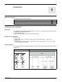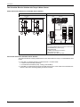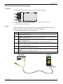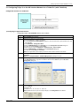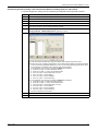
1
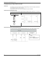
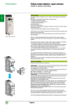
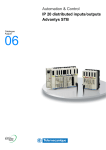
1672615 12/2009 TeSys U AS-interface Quick Start Guide 1672615 12/2009 www.schneider-electric.com The information provided in this documentation contains general descriptions and/or technical characteristics of the performance of the products contained herein. This documentation is not intended as a substitute for and is not to be used for determining suitability or reliability of these products for specific user applications. It is the duty of any such user or integrator to perform the appropriate and complete risk analysis, evaluation and testing of the products with respect to the relevant specific application or use thereof. Neither Schneider Electric nor any of its affiliates or subsidiaries shall be responsible or liable for misuse of the information contained herein. If you have any suggestions for improvements or amendments or have found errors in this publication, please notify us. No part of this document may be reproduced in any form or by any means, electronic or mechanical, including photocopying, without express written permission of Schneider Electric. All pertinent state, regional, and local safety regulations must be observed when installing and using this product. For reasons of safety and to help ensure compliance with documented system data, only the manufacturer should perform repairs to components. When devices are used for applications with technical safety requirements, the relevant instructions must be followed. Failure to use Schneider Electric software or approved software with our hardware products may result in injury, harm, or improper operating results. Failure to observe this information can result in injury or equipment damage. © 2009 Schneider Electric. All rights reserved. 2 1672615 12/2009 Table of Contents About the Book . . . . . . . . . . . . . . . . . . . . . . . . . . . . . . . . . . . . . . . . . . . . . . . Chapter 1 Introduction . . . . . . . . . . . . . . . . . . . . . . . . . . . . . . . . . . . . . . . . . . . . . . . . . 4 5 Presentation of the Application . . . . . . . . . . . . . . . . . . . . . . . . . . . . . . . . . . . . . . . . . . . . . . . . . The Schneider Electric Solution with Tesys U Motor Starter. . . . . . . . . . . . . . . . . . . . . . . . . . . 5 6 Chapter 2 Setting Up TeSys U. . . . . . . . . . . . . . . . . . . . . . . . . . . . . . . . . . . . . . . . . . . . 8 LUCA12BL and LUCD18BL Settings . . . . . . . . . . . . . . . . . . . . . . . . . . . . . . . . . . . . . . . . . . . . ASILUFC51 Connectors and Address Settings. . . . . . . . . . . . . . . . . . . . . . . . . . . . . . . . . . . . . 8 9 Chapter 3 Setting Up Communication Network to a PLC . . . . . . . . . . . . . . . . . . . . . . 10 3.1 Configuring TeSys U on the AS-interface Network for a Twido PLC (with TwidoSoft) . . . . 3.2 Configuring TeSys U on the AS-interface Network for a Premium PLC (with Unity Pro) . . 3.3 Implementing the TeSys U Solution with AS-i. . . . . . . . . . . . . . . . . . . . . . . . . . . . . . . . . . . 11 14 16 1672615 12/2009 3 About the Book At a Glance Document Scope The Quick Start Guide uses an application example to describe the different steps to quickly install, configure, and control TeSys U motor starters. With this Quick Start Guide, you can easily set up an AS-interface communication network, provided that you have a basic knowledge in PLCs and application software (TwidoSoft, Unity Pro). You do not need any other document to perform this task. For more details about other capabilities of TeSys U motor starters, consult the related documents listed below. Validity Note The information described in this Quick Start Guide is valid for the hardware and software used in the application example provided. The same procedures can be used with different versions of the hardware and software given provided that compatible versions are used. Related Documents Title of Documentation Reference Number TeSys U ASILUFC5-ASILUFC51 AS-i Communication Module - User Manual 1639093 LUB/LUS TeSys U Starters - Instruction Sheet 1629984 LUFC• - ASILUF - LULC• - Instruction Sheet 1743239 You can download these technical publications and other technical information from our website at www.schneider-electric.com. User Comments We welcome your comments about this document. You can reach us by e-mail at [email protected]. 4 1672615 12/2009 Introduction 1672615 12/2009 Introduction 1 What's in this Chapter? This chapter contains the following topics: Topic Page Presentation of the Application 5 The Schneider Electric Solution with Tesys U Motor Starter 6 Presentation of the Application Introduction The application example helps you to define Direct On Line (D.O.L.) motor starters step by step, in order to: provide thermal magnetic protection, control the motor, and obtain contactor feedback and circuit breaker trip feedback. Description of the Application Motor 1 (M1): 3-phase motor, class 10, 5.5 kW (7.4 hp) at 440 V, 50 Hz, rated current In = 10.5 A, D.O.L. Motor 2 (M2): 3-phase motor, class 20, 7.5 kW (10.1 hp) at 440 V, 50 Hz, rated current In = 14.7 A, D.O.L. with remote monitoring of motor load. Traditional Solution The scheme below shows wiring in the traditional solution: all control and feedback information is wired through a PLC. Power Scheme Control Scheme 440 V 50 Hz Q1 Q2 KM1 1672615 12/2009 KM2 M1 M2 5.5 kW 7.5 kW 5 Introduction The Schneider Electric Solution with Tesys U Motor Starter Power and Control Schemes in the Schneider Electric Solution Power Scheme Control Scheme 440 V 50 Hz Twido TeSys U TeSys U / LUCAppBL 1 A2 A1 A2 Q2 KM2 A1 Q1 KM1 LUCDppBL M1 24 Vdc A2 AS-i bus TeSys U TeSys U LUCApp LUCDpp ASILUFC51 A1 A2 A1 ASILUFC51 5.5 kW Premium M2 7.5 kW 24 Vdc AS-i bus 3 2 4 ASILUF C51 4 ASILUF C51 24 Vdc 5 6 1. Premium with TSXSAY1000 AS-interface master module, or Twido with TWDNOI10M3 AS-interface master module 2. ASIABLM3024 AS-i power supply 3. XZCG0122 cable 4. LU9BN11C prewired coil connection 5. XZCG0120 T-connector 6. XZCB10201 AS-i yellow, flat cable Control Units Used in the Schneider Electric Solution The Schneider Electric solution presented in this Quick Start Guide uses TeSys U to meet different client needs. 6 LUCA12BL is a standard control unit used with motor 1 for basic needs: Control a motor remotely (start/stop). Provide status information (ready, running, fault condition). LUCD18BL is an advanced control unit used with motor 2 for the same needs as the standard ones, and has a test button simulating tripping on thermal overload. 1672615 12/2009 Introduction Architecture of the TeSys U System The following architecture presents the main components of the TeSys U system mounted on a plate: 1 2 3 4 5 6 7 8 9 10 11 12 13 Legend Commercial Reference Description 1 Twido Programmable Logic Controller (PLC) Premium 2 XZCB10201 AS-interface flat cable, yellow, maximum 20 m (65.6 ft), to be cut according to the network size 3 ASIABLM3024 AS-interface power supply providing: 24 V DC, 3 A, 72 W for the auxiliary, and 30 V DC, 2.4 A, 72 W for AS-i 4 LUB12 TeSys U power base 5 LUCA12BL Standard control unit 6, 9 ASILUFC51 AS-interface communication module 7 LUB32 TeSys U power base 8 LUCD18BL Advanced control unit 10 XZCG0122 2 m (6.6 ft) cable with screw-on connector for connection to the flat cable and a stripped end for electrical connection 11 XZCG0120 T-connector for connection to the flat cable for AS-interface 12 LU9BN11C Prewired coil connection (optional), or 13 Standard connection Plug-in terminal block for wire-to-wire control of A1/A2 terminals supplied with ASILUFC51 Software Tools The following software tools must be used to set the applications. Their use requires a basic knowledge. Commercial Reference Description TWDSPU1002V10M TwidoSoft V3.2 TWD BTF U10M TwidoSuite V2.0 UNY SPU EFP CD40 Unity Pro Extra Large V4.0 programming software for Premium PLC Programming software for Twido PLC Network Conditions Protocol: AS-interface Addresses: 1A for TeSys U motor 1 2A for TeSys U motor 2 1672615 12/2009 7 Setting up TeSys U 1672615 12/2009 Setting Up TeSys U 2 What's in this Chapter? This chapter contains the following topics: Topic Page LUCA12BL and LUCD18BL Settings 8 ASILUFC51 Connectors and Address Settings 9 LUCA12BL and LUCD18BL Settings Setting Current on the Control Units The figure below shows how to set current on the control unit using a screwdriver (LUCA12BL here): LUCA / LUCD ys TeS 12BL A LUC 24V c 4.00A 5.00A 3.00A 12.0A 7.00A 9.00A 0 SS 1 CLA 3a ASILUFC51 Current Setting Values The table below shows the settings for LUCA12BL (Standard Control Unit) and LUCD18BL (Advanced Control Unit): 8 Control Unit Motor Current Setting Range Motor Nominal Power Current Setting Value = Motor Rated Current LUCA12BL M1 3...12 A 5.5 kW (7.5 hp) 10.5 A LUCD18BL M2 4.4...18 A 7.5 kW (10 hp) 14.7 A 1672615 12/2009 Setting up TeSys U ASILUFC51 Connectors and Address Settings Presentation The connectors under the ASILUFC51 communication module are as follows: A B C A B C Yellow connector for connection to AS-interface network or to ASITERV2 addressing terminal Black connector for connection to 24 V DC auxiliary Outputs to control the controller-starter Address Assign an address from 1A to 31A and from 1B to 31B using the ASITERV2 addressing terminal. Address 0 (zero) is not allowed and is considered an invalid configuration. To assign the addresses 1A and 2A proceed as follows: Step Action 1 Connect and screw in the male M12 connector of the XZMG12 cable to the M12 connector of the ASITERV2 addressing terminal. 2 Connect the yellow plug-in connector of the XZMG12 cable to the yellow AS-i bus connector on the ASILUFC51. See figure below. NOTE: The green plug-in connector of the XZMG12 cable is not used. 3 On the ASITERV2, turn the rotary switch to the ADDR position and then press the OK button. During initialization SEArcH displays. Result: The address of the connected slave appears on the display. The default address is 0. 4 Press the up and down arrows to set the address to 1. NOTE: An A appears on the display after the address to indicate the channel assignment because the slave has advanced addressing. 5 Press OK to apply the setting. During transmission ProG displays. Result: The slave address 1A displays permanently. 6 To set address 2A, press the ESC button and resume the process at step 4, setting the address to 2 instead of 1. Result: The slave address 2A displays permanently. 7 Turn the rotary switch to the OFF position and then disconnect the cables. ASILUFC51 ASITERV2 13.0137 1 M12 XZMG12 1672615 12/2009 9 Setting Up Communication Network to a PLC 1672615 12/2009 Setting Up Communication Network to a PLC 3 Introduction This chapter describes step by step how to set communication to a PLC. The table below indicates the software needed to set communication depending on the PLC used in the application. PLC Software Used to Set Communication Twido TwidoSoft (or TwidoSuite) Premium Unity Pro What's in this Chapter? This chapter contains the following topics: Topic 10 Page 3.1 Configuring TeSys U on the AS-interface Network for a Twido PLC (with TwidoSoft) 11 3.2 Configuring TeSys U on the AS-interface Network for a Premium PLC (with Unity Pro) 14 3.3 Implementing the TeSys U Solution with AS-i 16 1672615 12/2009 Setting Up Communication Network to a PLC 3.1 Configuring TeSys U on the AS-interface Network for a Twido PLC (with TwidoSoft) Configuration Process for a Twido PLC 1) Configuring the Application Network Configuration steps with TwidoSoft software are as follows: Step Action 1 Start TwidoSoft V3.2 software. 2 Configure the Twido PLC for AS-interface: From the File menu, create a new project. In the Functional Level Management dialog box, select the automatic, highest possible level, and then click OK. Click Hardware →Change PLC Base. Select TWDLMDA40D-K in the Controller list of the Change Base Controller dialog box. Confirm by clicking Change and then Done. Select the menu command Hardware →Expansion Bus →Add a module.... Select TWDNOI10M3 in the Module list of the Add module dialog box. Confirm by clicking Add and then Done. Result: The application browser displays the names of the chosen controller and module. 3 To configure the slaves of the master expansion module, right-click 1 : TWDNOI10M3, and then select Configure.... Result: The Configure Module - TWDNOI10M3 [Position 1] dialog box opens. 4 In the Configure Module - TWDNOI10M3 [Position 1] dialog box, configure the slave 1A: in the STD slaves/A bank, right-click the address cell 01 and then New to open the AS-i slave Configuration dialog box. 1 5 Address cell of the slave In the AS-i slave Configuration dialog box, enter the following values and then click OK to confirm: Name: Motor1 Address: 1A Profile: IO = 7 , ID = A , ID1 = 7 , ID2 = E Result: Addresses of the inputs and outputs display in the Configuration tab for Motor1: 1672615 12/2009 11 Setting Up Communication Network to a PLC Step Action 6 In the STD slaves/A bank, right-click the address cell 02 and then New to open the AS-i slave Configuration dialog box. 7 Enter or modify the following values and then click OK to confirm: Name: Motor2 Address: 2A Profile: IO = 7 , ID = A , ID1 = 7 , ID2 = E Result: Addresses of the inputs and outputs display in the Configuration tab for Motor2: 8 Confirm the slave configuration by clicking on OK. 9 The configuration editor displays the list of the 2 slaves with their addresses. 10 12 Save your application as a .twd file. 1672615 12/2009 Setting Up Communication Network to a PLC 2) Performing Functional Testing of the Communication Network including Twido PLC and Products To test the configuration, wiring, and communication with TwidoSoft software proceed as follows: Step Action 1 Connect the appropriate programming cable from your PC to the Twido PLC. 2 Power up the Twido PLC. 3 In TwidoSoft, click PLC →Connect... 4 In the connection window that opens, click the PC => Controller button. 5 Power up the 2 TeSys U systems. The green POWER LED on the ASILUFC51 front face blinks, and then remains constant. Communication is working correctly. 6 From the application browser in TwidoSoft, right-click TWDNOI10M3 and then select Configure: the Configure Module - TWDNOI10M3 [Position 1] dialog box opens. 7 Click on the Debug tab. Under AS-interface configuration, the green indicator lamp indicates this slave is active. Refer to the TeSys U ASILUFC5-ASILUFC51 AS-i Communication Module User Manual for details on how to name the topological addresses in such a way to avoid programming with names which do not provide any information of the contents of the memory location. In the application, the input/output variables for Motor1 are as follows: %QA1.1A.0 output = 0 means Stop direct direction %QA1.1A.0 output = 1 means Run forward direction %IA1.1A.0 input = 0 means Not ready or in fault %IA1.1A.0 input = 1 means Ready %IA1.1A.1 input = 0 means Stopped %IA1.1A.1 input = 1 means Running In the application, the input/output variables for Motor2 are as follows: %QA1.2A.0 output = 0 means Stop direct direction %QA1.2A.0 output = 1 means Run forward direction %IA1.2A.0 input = 0 means Not ready or in fault %IA1.2A.0 input = 1 means Ready %IA1.2A.1 input = 0 means Stopped %IA1.2A.1 input = 1 means Running The other variable bits are reserved. 1672615 12/2009 8 Click OK. 9 Click PLC →Disconnect. 13 Setting Up Communication Network to a PLC 3.2 Configuring TeSys U on the AS-interface Network for a Premium PLC (with Unity Pro) Configuration Process for a Premium PLC 1) Configuring the Application Network Configuration steps with Unity Pro XL software are as follows: Step Action 1 Start Unity Pro XL V4.0 software. 2 Configure the Premium PLC for AS-interface: From the File menu, create a new project. In the New Project window, expand the Premium list and select TSX P57 354M. Confirm by clicking OK. 3 From the Structural view of the Project Browser, select Configuration →0 : X Bus → 0 : TSX RKY 6EX, and then double-click to view the configuration. 4 In the Hardware catalog, select Premium local drop →Communication →TSX SAY 1000, and then drag and drop the TSX SAY 1000 module into an empty slot in the graphical configuration: 5 Double-click the TSX SAY 1000 module in the Structural view. The 0.2 : TSX SAY 1000 screen opens in a new tab which displays a Configuration tab. 6 Open the Associate Profile dialog box by double-clicking on cell 1 of the standard A slaves. 7 To configure the TeSys U systems, select the following values: Code 4 Motor-starters for the AS-i profile family ASILUFC51 under the corresponding AS-i catalog NOTE: If the TeSys U system does not appear in the list of AS-i profile families, click code 1 Private Family and then Add. In the dialog box which opens, enter ASILUFC51 in the name field and the associated profile. Confirm by clicking OK. Confirm by clicking OK. 14 1672615 12/2009 Setting Up Communication Network to a PLC Step 8 Action The Configuration tab displays: 1 Slave 2 ASILUFC51 profile (7.A.7.E) 3 Topological addresses (see Step 12 for renaming information) 9 10 Copy and paste ASILUFC51 from cell 1 to cell 2. Select the menu command Edit →Validate, or click to validate the configuration. 11 In the Project Browser, select Project →Variables & FB instances →Elementary Variables to set names to the topological addresses. The Data Editor screen opens in a new tab. 12 Name the variables in such a way to avoid programming with names which do no provide any information on the contents of the memory location. In the Variables tab: Enter one after the other the following name and corresponding topological address by doubleclicking the empty field in the related column: Forward_Motor1 corresponds to the %Q\1.2\0.0.0 address Reverse_Motor1 corresponds to the %Q\1.2\0.0.1 address Ready_Motor1 corresponds to the %I\1.2\0.0.0 address Running_Motor1 corresponds to the %I\1.2\0.0.1 address Select the variable type by selecting EBOOL in the Type column. 13 Select the menu command Build →Rebuild All Project to rebuild the project. If the values are correct (no errors), the NOT BUILT state changes to BUILT. 14 Save your application as an .stu file. 15 Connect the appropriate programming cable from your PC to the Premium PLC. 16 Power up the Premium PLC. 17 Click PLC →Connect in Unity Pro XL. 18 Click PLC →Transfer Project to PLC. 19 In the transfer window, click the Transfer button. 20 Click the Run icon. The input and output states appear in the Module AS-interface V2 window. 2) Performing Functional Testing of the Communication Network To test the configuration, wiring, and communication with Unity Pro XL software proceed as follows: Step 1672615 12/2009 Action 1 From the Structural view of the Project Browser, select your configuration. 2 In the Configuration window, check that no red points appear next to the tab names Module Fault and Debug. This means the program is running correctly. 3 In the Configuration window, select the Debug tab. 4 Under Channel test, select the slave number 1 and click on the Identification button. 5 A dialog box opens and should display that the exchange is OK. The COMM LED of the TeSys U blinks once for each identification request received. 15 Setting Up Communication Network to a PLC 3.3 Implementing the TeSys U Solution with AS-i Introduction The following motor-control schemes present wiring depending on the chosen solution and show the ease of programming using TeSys U with AS-i. Only the control of motor 1 (M1) used in the application example is described. Traditional Solution with Hard-wire Logic The scheme below shows hard-wire logic wiring in the traditional solution (without PLC, nor TeSys U): Power Scheme Control Scheme in Hard-wire Logic 440 V 50 Hz Q1 KM1 M1 5.5 kW Schneider Electric Solution with Programmable Logic The scheme below shows programmable logic wiring using a PLC and a TeSys U starter-controller: 16 1672615 12/2009 Setting Up Communication Network to a PLC TwidoSoft Programme for Controlling Motor 1 The following programme in TwidoSoft enables Motor 1 control: The following table presents the inputs and outputs and the corresponding AS-i variables: 1672615 12/2009 Symbol Address Description M1_NOT_READY %Q0.1 Indicator not ready or in fault M1_RUNNING %Q0.0 RUNNING indicator STOP_M1 %I0.1 STOP push-button RUN_M1 %I0.0 RUN push-button CMD_KM1 %QA1.1A.0 Command of KM1 “Motor 1” FEEDBACK_KM1_ON %IA1.1A.1 Feedback on the terminals’ position FEEDBACK_KM1_NOT_OK %IA1.1A.0 NOT READY or IN FAULT feedback of KM1 17