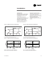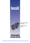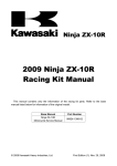
1
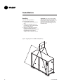
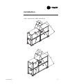
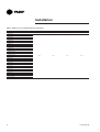
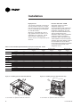
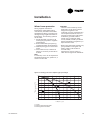
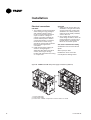
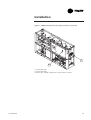
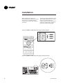
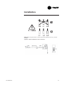
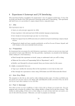
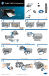
Installation
Operation
Maintenance
Indoor liquid chiller with integrated
hydraulic module
Water-cooled: CGWN 205 - 206 - 207 - 208 209 - 210 - 211 - 212 -213 - 214 - 215
Condenserless: CCUN 205 - 206 - 207 - 208 209 - 210 - 211 - 212 - 213 - 214 - 215
CG-SVX06D-E4
Trane Air Conditioning and
Refrigeration equipment
Environmental Protection / Compliance with F-Gas
regulation
This equipment contains a fluorinated gas covered by the Kyoto Protocol
[or an ozone depleting substance covered by Montreal Protocol].
The type and quantity of refrigerant per circuit is indicated on the product
nameplate
Global Warming Potential of the refrigerant implemented in Trane Air
Conditioning and Refrigeration Equipment
Refrigerant type
GWP (1) value
R407C
1 653
R22 (2)
1 780
R410A
1 975
The operator (contractor or end user) must check local environmental
regulations impacting installation, operation and disposal of the equipment;
in particular need to recover environmentally harmful substances
(refrigerant, oil, antifreeze agents, etc.)
Do not vent into the atmosphere any refrigerant. The handling of refrigerant
shall be fulfilled by a qualified service engineer.
(1) GWP = global warming potential
(2) Covered by Montreal Protocol
2
CG-SVX06D-E4
General information
Foreword
These instructions are given as a
guide to good practice in the
installation, start-up, operation, and
maintenance by the user, of Trane
CGWN/CCUN chillers. They do not
contain full service procedures
necessary for the continued
successful operation of this
equipment. The services of a
qualified technician should be
employed through the medium of a
maintenance contract with a
reputable service company.
Warranty
Warranty is based on the general
terms and conditions of the
manufacturer. The warranty is void
if the equipment is repaired or
modified without the written
approval of the manufacturer, if the
operating limits are exceeded or if
the control system or the electrical
wiring is modified. Damage due to
misuse, lack of maintenance or
failure to comply with the
manufacturer's instructions or
recommendations is not covered by
the warranty obligation. If the user
does not conform to the rules of
this manual, it may entail
cancellation of warranty and
liabilities by the manufacturer.
Reception in all countries
except France:
In case of concealed damage: The
consignee (or the site
representative) must send a
registered letter to the last carrier
within 7 days of delivery, claiming
for the described damage. A copy
of this letter must be sent to Trane
Epinal Operations - Claims team.
Note: for deliveries in France, even
concealed damage must be looked
for at delivery and immediately
treated as visible damage.
About this manual
Warnings and cautions appear at
appropriate places in this
instruction manual. Your personal
safety and the proper operation of
this machine require that you follow
them carefully. The constructor
assumes no liability for installations
or servicing performed by
unqualified personnel.
About the unit
Reception
These CGWN/CCUN units are
assembled, pressure tested,
dehydrated, charged and run tested
before shipment. The information
contained in this manual applies to
units designated CGWN and CCUN.
On arrival, inspect the unit before
signing the delivery note.
Refrigerant
Reception in France only:
In case of visible damage: The
consignee (or the site
representative) must specify any
damage on the delivery note,
legibly sign and date the delivery
note, and the truck driver must
countersign it. The consignee (or
the site representative) must notify
Trane Epinal Operations - Claims
team and send a copy of the
delivery note. The customer (or the
site representative) should send a
CG-SVX06D-E4
registered letter to the last carrier
within 3 days of delivery.
The refrigerant provided by the
manufacturer meets all the
requirements of our units. When
using recycled or reprocessed
refrigerant, it is advisable to ensure
its quality is equivalent to that of a
new refrigerant. For this, it is
necessary to have a precise analysis
made by a specialized laboratory. If
this condition is not respected, the
manufacturer warranty could be
cancelled.
3
Contents
Trane Air Conditioning and
Refrigeration equipment
2
Environmental protection Compliance with F-Gas regulation
2
General information
3
Foreword
Warranty
Reception
About this manual
About the unit
Refrigerant
3
3
3
3
3
3
General data
6
Installation
13
Unit nameplate
Installation instructions
Handling
Minimal installation water content
Water treatment
Water connections
Refrigerant line connections
Winter freeze protection
Electrical connections
Interconnection between CCUN and Remote Condenser
4
CG-SVX06D-E4
13
13
14
17
17
18
26
33
34
38
Contents
General start-up
40
Preparation
Start-up
Operation
40
41
53
Installation checklist
Control and unit operation
Weekly start up
Weekend shutdown
Seasonal shutdown
Seasonal start-up
Maintenance
53
54
54
54
54
55
56
Maintenance instructions
Troubleshooting guide
Safety recommendations
Maintenance contract
Training
CG-SVX06D-E4
56
58
60
60
60
5
General Data
Table 1 - Water Cooled units: CGWN standard - R410A
Eurovent Performances (1)
Net Cooling Capacity
Total Power input in cooling
Evaporator water pressure drop
Evaporator head pressure available (4)
Condenser water pressure drop
Condenser head pressure available
Main Power supply
Sound Power Level (4)
Sound Power Level (4) w/ sound attenuation jacket
Units Amps
Nominal (3)
Start-up Amps
Standard unit
With soft starter option
Short circuit unit capacity
Max supply cable size
Min supply cable size
Compressor
Number
Type
Model
Speeds number
Motors Number
Rated Amps (compA/CompB) (3)
Locked rotor Amps (compA/CompB)
Motor RPM
Power factor (compA/CompB)
Sump Heater (compA/CompB)
Evaporator
Number
Type
Model
Water volume (total)
Antifreeze Heater
Evaporator Water Connections
Diameter
Max. water-side operating pressure
without hydraulic module
with hydraulic module
Condenser
Number
Type
Model
Water volume (total)
Antifreeze Heater
Condenser Water Connections
Diameter
Max. water-side operating pressure
without hydraulic module
with hydraulic module suction/discharge
Dimensions
Height
Length
Width
Operating Weight
Base Unit
Evap Hyd Kit
Evap + Cds Hyd Kit
Shipping Weight
Base Unit
Evap Hyd Kit
Evap + Cds Hyd Kit
System Data
Refrigerant circuit
Capacity steps
Minimum capacity
Refrigerant Charge (2)
Circuit 1 & 2
Oil Charge (2)
Circuit 1 & 2
(1)
(2)
(3)
(4)
6
CGWN
205
CGWN
206
CGWN
207
CGWN
208
CGWN
209
CGWN
210
CGWN
211
(kW)
(kW)
(kPa)
(kPa)
(kPa)
(kPa)
182.5
42.5
57
161
59
151
217.0
50.2
59
141
64
134
251.7
57.7
55
142
60
138
312.1
70.1
42
143
52
150
341.9
78.2
50
188
63
132
373.7
85.9
54
176
65
117
(dBA)
(dBA)
82
79
82
79
83
80
283.1
61.5
42
149
47
162
400/3/50
83
80
84
81
84
81
84
81
(A)
144
163
187
210
233
250
263
(A)
(A)
(kA)
( mm2)
( mm2)
274
210
15
150
35
338
252
15
150
35
395
291
15
150
50
418
314
15
150
50
441
337
15
150
70
512
384
15
240
70
525
397
15
240
70
(25T+25T)
(25T+30T)
(30T+30T)
52/52
260/260
52/58
260/320
58/58
320/320
0.84/0.84
0.84/0.88
0.88/0.88
DP400-186
39.2
-
DP400-206
43.4
-
4”
4”
DP400-206
43.4
-
DP400-222
46.7
-
4”
4”
(A)
(A)
(rpm)
(15T+15T)
(15T+20T)
(20T+20T)
31/31
160/160
31/40
160/215
40/40
215/215
0.82/0.82
0.82/0.87
0.87/0.87
(W)
(L)
(W)
DP400-74
15.6
-
DP400-90
18.9
-
3”
3”
1
Brazed plate
DP400-114 DP400-162
DP400-186
24.0
34.1
39.2
Grooved pipe connection
4”
4”
4”
(kPa)
(kPa)
(L)
(W)
4
Scroll
(20T+25T)
1
1
40/52
215/260
2900
0.87/0.84
160/160
1000
400
DP400-90
18.9
3 or 4”
1
Brazed plate
DP400-114 DP400-134 DP400-186
DP400-206
24.0
28.2
39.2
43.4
Grooved pipe connection
3 or 4”
3 or 4”
4”
4”
(kPa)
(kPa)
1000
400/640
(mm)
(mm)
(mm)
1842
2545
880
1842
2545
880
1842
2545
880
1842
2545
880
1842
2545
880
1842
2545
880
1842
2545
880
(kg)
(kg)
(kg)
1360
1450
1520
1300
1390
1460
1420
1590
1690
1500
1670
1770
1650
1820
1920
1710
1880
1980
1790
1960
2060
(kg)
(kg)
(kg)
1290
1380
1450
1220
1310
1380
1320
1490
1590
1370
1540
1640
1510
1680
1780
1570
1740
1840
1650
1820
1920
%
4
25
4
21
4
25
2
4
22
4
25
4
23
4
25
(kg)
10
11
13
17
18
18
19
(l)
13.4
13.4
13.4
13.4
13.4
13.9
14.4
at Eurovent Conditions (Evap 12°C/7°C - Condenser. 30°C/35°C)
per circuit
Max rated conditions.
Dual Pump Option
CG-SVX06D-E4
General Data
Table 2 - Water Cooled units: CGWN standard - R407C
Eurovent Performances (1)
Net Cooling Capacity
Total Power input in cooling
Evaporator water pressure drop
Evaporator head pressure available (4)
Condenser water pressure drop
Condenseur head pressure available
Main Power supply
Sound Power Level (4)
Sound Power Level w/ sound attenuation jacket (4)
Units Amps
Nominal (3)
Start-up Amps
Standard unit
With soft starter option
Short circuit unit capacity
Max supply cable size
Min supply cable size
Compressor
Number
Type
Model
Speeds number
Motors Number
Rated Amps (compA/CompB) (3)
Locked rotor Amps (compA/CompB)
Motor RPM
Power factor (compA/CompB)
Sump Heater (compA/CompB)
Evaporator
Number
Type
Model
Water volume (total)
Antifreeze Heater
Evaporator Water Connections
Diameter
Max. water-side operating pressure,
without hydraulic module
with hydraulic module
Condenser
Number
Type
Model
Water volume (total)
Antifreeze Heater
Condenser Water Connections
Diameter
Max. water-side operating pressure,
without hydraulic module
with hydraulic module
Dimensions without Hydraulic Module
Height
Length
Width
Dimensions with Hydraulic Module
Height
Length
Width
Operating Weight
Base Unit w/o Hyd Kit
Base Unit with Hyd Kit
Evap Hyd Kit
Cds Hyd Kit
Evap + Cds Hyd Kit
Shipping Weight
Base Unit w/o Hyd Kit
Base Unit with Hyd Kit
Evap Hyd Kit
Cds Hyd Kit
Evap + Cds Hyd Kit
System Data
Number of Refrigerant circuit
Capacity steps
Minimum capacity
Refrigerant Charge (2)
Circuit A & B
Oil Charge (2)
Circuit A & B
(1) at Eurovent Conditions (Evap 12°C/7°C - Condenser 30°C/35°C)
(2) per circuit
CG-SVX06D-E4
CGWN
212
CGWN
213
CGWN
214
CGWN
215
(kW)
(kW)
(kPa)
(kPa)
(kPa)
(kPa)
398.6
97.0
40
236
66
159
431.3
106.4
47
218
64
151
466.0
117.3
49
200
59
147
506.4
125.5
48
187
56
136
(dBA)
(dBA)
87
84
88
85
88
85
90
87
400/3/50
(A)
311
337
370
400
(A)
(A)
(kA)
(mm2)
(mm2)
563
439
15
185
240
588
465
15
185
240
621
498
15
240
240
655
530
15
240
240
5
6
(25T+30T)
(25T)
52/62.5
272/310
2900
0.87/0.87
150
52/52
272/272
2900
0.87/0.87
150
6
6
(25T+30T)
(30T)
52/62.5
272/310
2900
0.87/0.87
150
62.5/62.5
310/310
2900
0.87/0.87
150
Scroll
1
1
(A)
(A)
(rpm)
(W)
1
Brazed plate
AC350-190DQ
AC350-210DQ
38
42
Grooved pipe connections
4"
(L)
(W)
AC350-190DQ
38
-
(kPa)
(kPa)
1000
400
(L)
(W)
B400T- 94p / 114p
19 / 23
-
(kPa)
(kPa)
1000
400
1000
400
1000
400
1000
400
(mm)
(mm)
(mm)
1950
2808
878
1950
2808
878
1950
2808
878
1950
2808
878
(mm)
(mm)
(mm)
1950
3498
878
1950
3498
878
1950
3498
878
1950
3498
878
(kg)
(kg)
(kg)
(kg)
(kg)
2232
2128
490
374
682
2442
2337
490
374
682
2525
2420
490
374
682
2640
2500
490
374
682
(kg)
(kg)
(kg)
(kg)
(kg)
2109
2048
432
317
662
2315
2253
432
317
662
2387
2326
432
317
662
2492
2408
432
317
662
%
5
18
6
16
6
15
6
16
(kg)
22 / 21
22 / 22
25 / 23
26 / 26
(l)
20.4 / 12.6
20.4 / 20.4
18.9 / 20.4
18.9 / 18.9
1000
400
1000
400
2
Brazed plate
B400T- 114p / 114p
B400T- 114p / 144p
23 / 23
23 / 29
Grooved pipe connections
5"
AC350-230DQ
46
-
1000
400
B400T- 144p / 144p
29 / 29
-
2
(3) Max rated conditions.
(4) Dual Pump Option
7
General Data
Table 3 - Water Cooled units: CGWN High Efficiency (HE) - R410A
Eurovent Performances (1)
Net Cooling Capacity
Total Power input in cooling
Evaporator water pressure drop
Evaporator head pressure available (4)
Condenser water pressure drop
Condenseur head pressure available
Main Power supply
Sound Power Level (4)
Sound Power Level w/ sound attenuation jacket (4)
Units Amps
Nominal (3)
Start-up Amps
Standard unit
With soft starter option
Short circuit unit capacity
Max supply cable size
Min supply cable size
Compressor
Number
Type
Model
Speeds number
Motors Number
Rated Amps (compA/CompB) (3)
Locked rotor Amps (compA/CompB)
Motor RPM
Power factor (compA/CompB)
Sump Heater (compA/CompB)
Evaporator
Number
Type
Model
Water volume (total)
Antifreeze Heater
Evaporator Water Connections
Diameter
Max. water-side operating pressure.
without hydraulic module
with hydraulic module
Condenser
Number
Type
Model
Water volume (total)
Antifreeze Heater
Condenser Water Connections
Diameter
Antifreeze heater
Max. water-side operating pressure
without hydraulic module
with hydraulic module suction/discharge
Dimensions
Height
Length
Width
Operating Weight
Base Unit
Evap Hyd Kit
Evap + Cds Hyd Kit
Shipping Weight
Base Unit
Evap Hyd Kit
Evap + Cds Hyd Kit
System Data
Refrigerant circuit
Capacity steps
Minimum capacity
Refrigerant Charge (2)
Circuit A & B
Oil Charge (2)
Circuit A & B
(1)
(2)
(3)
(4)
8
CGWN
205 HE
CGWN
206 HE
CGWN
207 HE
(kW)
(kW)
(kPa)
(kPa)
(kPa)
(kPa)
193.3
40.1
26
188
31
177
227.4
47.9
36
156
42
154
262.4
55.7
37
160
41
173
(dBA)
(dBA)
82
79
82
79
83
80
(A)
144
163
187
(A)
(A)
(kA)
(mm2)
(mm2)
274
210
15
150
35
338
252
15
150
35
395
291
15
150
50
(15T+15T)
(A)
(A)
(rpm)
(W)
(l)
(W)
(kPa)
(kPa)
(l)
(W)
31/31
160/160
2900
0.82/0.82
160/160
3" (80)
1
Brazed plate
DV58-154
32.4
Grooved pipe connections
3" (80)
1000
400
1000
400
DV58-138
32.4
DP400-162
34.1
(W)
(kPa)
(kPa)
4
Scroll
(15T+20T)
1
1
31/40
160/215
2900
0.82/0.87
160/160
1000
400/640
(mm)
(mm)
(mm)
Brazed plate
DP400-162
34.1
Grooved pipe connection
3” (80)
1000
400/640
(20T+20T)
40/40
215/215
2900
0.87/0.87
160/160
DV58-170
34.1
4" (100)
1000
400
DP400-186
39.2
1000
400/640
1842
2545
880
(kg)
(kg)
(kg)
1460
1550
1620
1450
1540
1610
1470
1640
1740
(kg)
(kg)
(kg)
1360
1450
1520
1350
1440
1510
1340
1510
1610
%
4
25
2
4
21
4
25
(kg)
15
15
17
(l)
13.4
13.4
13.4
at Eurovent Conditions (Evap 12°C/7°C - Condenser. 30°C/35°C)
per circuit
Max rated conditions.
Dual Pump Option
CG-SVX06D-E4
General Data
Table 4 - Condenserless units: CCUN standard - R410A
Eurovent Performances (1)
Net Cooling Capacity
Total Power input in cooling
Evaporator water pressure drop
Evaporator head pressure available (4)
Main Power supply
Sound Power Level (4)
Sound Power Level (4) w/ sound attenuation jacket
Units Amps
Nominal (3)
Start-up Amps
Standard unit
With soft starter option
Short circuit unit capacity
Max supply cable size
Min supply cable size
Compressor
Number
Type
Model
Speeds number
Motors Number
Rated Amps (compA/CompB)
Locked rotor Amps (compA/CompB)
Motor RPM
Power factor (compA/CompB)
Sump Heater (compA/CompB)
Evaporator
Number
Type
Model
Water volume (total)
Antifreeze Heater
Evaporator Water Connections
Diameter
Max. water-side operating pressure
without hydraulic module
with hydraulic module
Remote condenser connections
Discharge line diameter circuit 1 & 2
Liquid line diameter circuit 1 & 2
Dimensions
Height
Length
Width
Operating Weight
Base Unit
Evap Hyd Kit
Shipping Weight
Base Unit
Evap Hyd Kit
System Data
Refrigerant circuit
Capacity steps
Minimum capacity
Refrigerant Charge (2)
Circuit 1 & 2
Oil Charge (2)
Circuit 1 & 2
(1)
(2)
(3)
(4)
CCUN
205
CCUN
206
CCUN
207
CCUN
208
CCUN
209
CCUN
210
CCUN
211
(kW)
(kW)
(kPa)
(kPa)
166.3
45.6
48
178
198.1
53.8
49
161
230.4
62.0
47
153
281.9
77.7
34
157
311.4
86.4
41
200
343.8
95.1
46
189
(dBA)
(dBA)
82
79
82
79
83
80
257.7
69.8
35
160
400/3/50
83
80
84
81
84
81
84
81
(A)
132
151
172
195
218
236
249
(A)
(A)
(kA)
(mm2)
( mm2)
262
198
15
150
35
326
240
15
150
35
381
277
15
150
50
404
300
15
150
50
427
323
15
150
70
498
370
15
240
70
511
383
15
240
70
(15T+15T)
(15T+20T)
(20T+20T)
(25T+25T)
(25T+30T)
(30T+30T)
31/31
160/160
31/40
160/215
40/40
215/215
52/52
260/260
52/58
260/320
58/58
320/320
0.82/0.82
0.82/0.87
0.87/0.87
0.84/0.84
0.84/0.88
0.88/0.88
DP400-186
39.2
-
DP400-206
43.4
-
4”
4”
(A)
(A)
(rpm)
(W)
(L)
(W)
DP400-74
15.6
-
DP400-90
18.9
-
3”
3”
4
Scroll
(20T+25T)
1
1
40/52
215/260
2900
0.87/0.84
160/160
1
Brazed plate
DP400-114
DP400-162
DP400-186
24.0
34.1
39.2
Grooved pipe connections
4”
4”
4”
(kPa)
(kPa)
1000
400
1"3/8
7/8
1"3/8
7/8
1"3/8
7/8
1"5/8
7/8
1"5/8
7/8
1"5/8
1"1/8
1"5/8
1"1/8
(mm)
(mm)
(mm)
1842
2545
880
1842
2545
880
1842
2545
880
1842
2545
880
1842
2545
880
1842
2545
880
1842
2545
880
(kg)
(kg)
1260
1350
1170
1260
1270
1440
1280
1450
1420
1590
1480
1650
1550
1720
(kg)
(kg)
1210
1300
1120
1210
1200
1370
1190
1360
1320
1490
1380
1550
1450
1620
%
4
25
4
21
4
25
2
4
22
4
25
4
23
4
25
(kg)
3
3
3
3
3
3
3
(l)
13.4
13.4
13.4
13.4
13.4
13.9
14.4
Conditions (Evap 12°C/7°C - Saturated discharge 45°C - 5°C subcooling)
per circuit
Max rated conditions.
Dual Pump Option
CG-SVX06D-E4
9
General Data
Table 5 - Condenserless units: CCUN standard - R407C
Eurovent Performances (1)
Net Cooling Capacity
Total Power input in cooling
Evaporator water pressure drop
Evaporator head pressure available (4)
Main Power supply
Sound Power Level (4)
Sound Power Level w/ sound attenuation jacket (4)
Units Amps
Nominal (3)
Start-up Amps
Standard unit
With soft starter option
Short circuit unit capacity
Max supply cable size
Min supply cable size
Compressor
Number
Type
Model
Speeds number
Motors Number
Rated Amps (compA/CompB) (3)
Locked rotor Amps (compA/CompB)
Motor RPM
Power factor (compA/CompB)
Sump Heater (compA/CompB)
Evaporator
Number
Type
Model
Water volume (total)
Antifreeze Heater
Evaporator Water Connections
Diameter
Max. water-side operating pressure,
without hydraulic module
with hydraulic module
Remote condenser connections
Discharge line diameter circuit 1 & 2
Liquid line diameter circuit 1 & 2
Dimensions without Hydraulic Module
Height
Length
Width
Dimensions with Hydraulic Module
Height
Length
Width
Operating Weight
Base Unit w/o Hyd Kit
Base Unit with Hyd Kit
Evap Hyd Kit
Shipping Weight
Base Unit w/o Hyd Kit
Base Unit with Hyd Kit
Evap Hyd Kit
System Data
Refrigerant circuit
Capacity steps
Minimum capacity
Refrigerant Charge (2)
Circuit A & B
Oil Charge (2)
Circuit A & B
(1) Conditions (Evap 12°C/7°C - Saturated discharge 45°C - 5°C subcooling)
(2) per circuit
10
CCUN
212
CCUN
213
CCUN
214
CCUN
215
(kW)
(kW)
(kPa)
(kPa)
385.6
99.0
38
242
417.3
108.5
44
227
450.4
120.5
46
211
486.9
131.1
45
197
(dBA)
(dBA)
87
84
88
85
88
85
90
87
400/3/50
(A)
280
306
339
369
(A)
(A)
(kA)
(mm2)
(mm2)
532
408
15
185
240
557
434
15
185
240
590
467
15
240
240
624
499
15
240
240
5
6
6
6
(25T+30T)
(30T)
52/62.5
272/310
2900
0.87/0.87
150
62.5/62.5
310/310
2900
0.87/0.87
150
Scroll
(25T+30T)
(25T)
1
1
(A)
(A)
(rpm)
(W)
52/62.5
272/310
2900
0.87/0.87
150
52/52
272/272
2900
0.87/0.87
150
1
Brazed plate
AC350-190DQ
AC350-210DQ
38
42
no
no
Grooved pipe connections
4"
(l)
(W)
AC350-190DQ
38
no
AC350-230DQ
46
no
(kPa)
(kPa)
1000
400
1000
400
1000
400
1000
400
2"1/8
1"3/8
2"1/8
1"3/8
2"1/8
1"3/8
2"1/8
1"3/8
(mm)
(mm)
(mm)
1950
2808
878
1950
2808
878
1950
2808
878
1950
2808
878
(mm)
(mm)
(mm)
1950
3498
878
1950
3498
878
1950
3498
878
1950
3498
878
(kg)
(kg)
(kg)
1879
1880
490
2070
2071
490
2120
2122
490
2180
2182
490
(kg)
(kg)
(kg)
1832
1842
432
2023
2033
432
2070
2080
432
2130
2136
432
%
4
22
4
33
4
30
4
33
18.9 / 20.4
18.9 / 18.9
2
(kg)
(l)
Holding charge
20.4 / 12.6
20.4 / 20.4
(3) Max rated conditions.
(4) Dual Pump Option
CG-SVX06D-E4
General Data
Table 6 - Condenserless units: CCUN High Efficiency (HE) - R410A
Eurovent Performances (1)
Net Cooling Capacity
Total Power input in cooling
Evaporator water pressure drop
Evaporator head pressure available (4)
Main Power supply
Sound Power Level (4)
Sound Power Level w/ sound attenuation jacket (4)
Units Amps
Nominal (3)
Start-up Amps
Standard unit
With soft starter option
Short circuit unit capacity
Max supply cable size
Min supply cable size
Compressor
Number
Type
Model
Speeds number
Motors Number
Rated Amps (compA/CompB) (3)
Locked rotor Amps (compA/CompB)
Motor RPM
Power factor (compA/CompB)
Sump Heater(compA/CompB)
Evaporator
Number
Type
Model
Water volume (total)
Antifreeze Heater
Evaporator Water Connections
Diameter
Max. water-side operating pressure
without hydraulic module
with hydraulic module
Remote condenser connections
Discharge line diameter circuit 1 & 2
Liquid line diameter circuit 1 & 2
Dimensions
Height
Length
Width
Operating Weight
Base Unit
Evap Hyd Kit
Shipping Weight
Base Unit
Evap Hyd Kit
System Data
Refrigerant circuit
Capacity steps
Minimum capacity
Refrigerant Charge (2)
Circuit 1 & 2
Oil Charge (2)
Circuit 1 & 2
CCUN
205 HE
CCUN
206 HE
CCUN
207 HE
(kW)
(kW)
(kPa)
(kPa)
175.0
45.6
22
190
239.1
62.0
30
170
(dBA)
(dBA)
82
79
206.7
53.8
29
170
400/3/50
82
79
(A)
132
151
172
(A)
(A)
(kA)
(mm2)
(mm2)
262
198
15
150
35
326
240
15
150
35
381
277
15
150
50
(15T+15T)
(A)
(A)
(rpm)
(W)
(L)
(W)
(kPa)
(kPa)
31/31
160/160
2900
0.82/0.82
160/160
DP400-154
32.4
4
Scroll
(15T+20T)
1
1
31/40
160/215
2900
0.82/0.87
160/160
1
Brazed plate
DP400-154
32.4
Grooved pipe connections
3"
(20T+20T)
40/40
215/215
2900
0.87/0.87
160/160
DP400-162
34.1
1000
400
1000
400
1000
400
7/8
1"3/8
7/8
7/8
(mm)
(mm)
(mm)
1842
2545
880
(kg)
(kg)
1330
1420
1240
1330
1250
1420
(kg)
(kg)
1270
1360
1170
1260
1160
1330
25
2
4
21
25
%
(kg)
(l)
(1) Conditions (Evap 12°C/7°C - Saturated discharge 45°C - 5°C subcooling)
(2) per circuit
CG-SVX06D-E4
83
80
Holding charge
13.4
13.4
13.4
(3) Max rated conditions.
(4) Dual Pump Option
11
General Data
Table 7 - Evaporator hydraulic module
205
206
207
208
209
210
211
212
213
214
215
(kW)
4.0
4.0
5.5
5.5
5.5
7.5
7.5
11.0
11.0
11.0
11.0
(A)
7.5
7.5
11.1
11.1
11.1
14.7
14.7
20.0
20.0
20.0
20.0
High head pressure option
Nb Pump set
Motor (1)(2)
Rated Amps (1)(2)
Motor RPM
1
(rpm)
2900
Low head pressure option
Nb Pump set
Motor (1)(2)
Rated Amps (1)(2)
Motor RPM
1
(kW)
2.2
2.2
4.0
4.0
4.0
5.5
5.5
4.0
4.0
5.5
5.5
(A)
4.0
4.0
7.5
7.5
7.5
11.1
11.1
7.8
7.8
10.3
10.3
(rpm)
2900
Expansion tank volume
(l)
25
25
25
25
25
25
25
35
35
35
35
User volume expansion capacity (3)
(l)
3600
3600
3600
3600
3600
3600
3600
5100
5100
5100
5100
3"
3"
4"
4"
4"
4"
4"
4"
4"
4"
4"
211
212
213
214
215
Water strainer diameter
Piping
Steel
Table 8 - Condenser hydraulic module
205
206
207
208
209
210
(kW)
3
3
4
4
4
4
4
7.5
7.5
7.5
7.5
(A)
6.1
6.1
7.7
7.7
7.7
7.7
7.7
13.8
13.8
13.8
13.8
High head pressure option
Nb Pump set
Motor (1)(2)
Rated Amps (1)(2)
Motor RPM
2 (in parallel)
(rpm)
2900
Low head pressure option
Nb Pump set
Motor (1)(2)
Rated Amps (1)(2)
Motor RPM
Water strainer Diameter
Piping
2 (in parallel)
(kW)
2.2
2.2
3.0
3.0
3.0
3.0
3.0
4.0
4.0
5.5
5.5
(A)
4.2
4.2
6.1
6.1
6.1
6.1
6.1
7.8
7.8
10.3
10.3
4"
4"
4"
4"
4"
4"
4"
4"
4"
4"
(rpm)
2900
4"
Steel
(1) Per motor
(2) Dual Pump Option
(3) Hydrostatic pressure 3 bar at 25°C with 7°C mini
12
CG-SVX06D-E4
Installation
Unit nameplate
Clearance
The unit nameplate gives the
complete model reference numbers.
The unit power rating is shown, and
power supplies should not deviate by
more than 5% from the rated power.
Compressor motor amperage is
shown in box I.MAX. The customer's
electrical installation must be able to
withstand this current.
Respect recommended clearance
around the unit to allow maintenance
operation to take place without
obstruction. For minimum clearance,
consult the certified submittals,
which are available on request from
your Trane Agency.
Installation instructions
Foundations
No special foundations are required,
provided the supporting surface is
flat and level, and can withstand the
weight or the unit.
Isolating rubber pads
6 pads are supplied as standard with
the machine (55x150mm). They
should be placed between the
supporting floor and the unit to
isolate from the ground. Trane does
not recommend to install spring
isolators.
Water drain hole
Install a drain hole wide enough to
drain away water from the unit in the
event of shut-down or repair.
CG-SVX06D-E4
13
Installation
Handling
A specific lifting method is
recommended as follows:
1. 4 lifting points are built into the
unit.
2. Slings and spreader bar to be
provided by rigger and attached
to the 4 lifting points.
3. Minimum rated lifting capacity
(vertical) of each sling and
spreader bar shall be no less than
the tabulated unit shipping
weight. Refer to Figures 1 and 2
CAUTION: This unit must be lifted
with the outmost care. Avoid shock
load by lifting slowly and evenly. To
prevent any damage, position the
lifting bar so that the slings do not
touch the unit.
Figure 1 - Rigging the unit - CGWN - CCUN (205-211)
A
B
C
D
14
CG-SVX06D-E4
Installation
Figure 2 - Rigging the unit - CGWN - CCUN (212-215)
C
A
B
D
C
A
B
D
CG-SVX06D-E4
15
Installation
Table 9 - Dimensions of recommended slings and swing-bar
CGWN 205
CGWN 206
CGWN 207
CGWN 208
CGWN 209
CGWN 210
CGWN 211
CGWN 212
CGWN 213
CGWN 214
CGWN 215
CGWN 205 HE
CGWN 206 HE
CGWN 207 HE
CCUN 205
CCUN 206
CCUN 207
CCUN 208
CCUN 209
CCUN 210
CCUN 211
CCUN 212
CCUN 213
CCUN 214
CCUN 215
CCUN 205 HE
CCUN 206 HE
CCUN 207 HE
16
A (mm)
B (mm)
C (mm)
D (mm)
1100
600
500
2400
CG-SVX06D-E4
Installation
Minimal installation water
content
Water treatment
Untreated or insufficiently treated
water, if used in this unit, may cause
scale, slime or algae to accumulate
or cause erosion and corrosion. As
Trane does not know the
components used in the hydraulic
network and the quality of the water
used, we recommend the services of
a qualified water treatment specialist.
The following materials are used in
Trane chillers heat exchangers:
• Stainless steel plates AISI 316,
1.4401 with copper brazing
• Water piping: steel
• Water connections: brass
Trane will not accept any liability in
regards of damage due to the use of
untreated or improperly treated
water or from the use of saline or
brackish water. If water treatment is
required, contact your local Trane
sales office.
The water volume is an important
parameter because it allows a stable
chilled water temperature and avoids
short cycle operation of the
compressors.
Parameters which influence the
water temperature stability
• Water loop volume
• Load fluctuation
• Number of capacity steps
• Compressors rotation
• Dead band
• Minimum time between 2 starts
of a compressor
The following table gives the
minimal installation water content
recommended according to all these
parameters for both comfort and
process cooling application.
Table 10 - Minimal water content
Confort Application
Process cooling Application
2°C Dead
band (1)
3°C Dead
band (2)
4°C Dead
band (3)
2°C Dead
band (1)
3°C Dead
band (2)
4°C Dead
band (3)
CGWN - CCUN 205
660 l
440 l
330 l
1160 l
730 l
530 l
CGWN - CCUN 206
670 l
450 l
340 l
1160 l
740 l
540 l
CGWN - CCUN 207
650 l
440 l
330 l
1100 l
710 l
520 l
CGWN - CCUN 208
880 l
580 l
440 l
1520 l
960 l
710 l
CGWN - CCUN 209
1060 l
700 l
530 l
1860 l
1170 l
860 l
CGWN - CCUN 210
1080 l
720 l
540 l
1870 l
1190 l
870 l
CGWN - CCUN 211
1260 l
840 l
630 l
2220 l
1400 l
1020 l
CGWN - CCUN 212
1260 l
840 l
630 l
2170 l
1380 l
1010 l
CGWN - CCUN 213
1050 l
700 l
530 l
1760 l
1130 l
830 l
CGWN - CCUN 214
1270 l
850 l
640 l
2150 l
1370 l
1010 l
CGWN - CCUN 215
1240 l
820 l
620 l
2060 l
1330 l
980 l
Notes
(1) Minimum water loop volume in order to obtain maximum +/- 1°C chilled water temperature fluctuation vs. Chilled
water set-point
(2) Minimum water loop volume in order to obtain maximum +/- 1.5°C chilled water temperature fluctuation vs.
Chilled water set-point
(3) Minimum water loop volume in order to obtain maximum +/- 2°C chilled water temperature fluctuation vs. Chilled
water set-point
This table is estimated with
Condenser : Water 30°/35°C
Evaporator : Water 12°/7°C
CG-SVX06D-E4
17
Installation
Water connections
Before making any connections,
make sure the labeling for entering
and leaving water corresponds to the
submittals. CGWN water-cooled
chillers and CCUN condenserless
units are available in several
versions:
1) Evaporator side options
• No hydraulic control
• With pump contactors to control a
remote pump (single or dual)
• With pump integrated hydraulic
module, single or dual pump, low
or high pressure head
2) Condenser side options
• No hydraulic control
• With pump contactors to control a
remote pump (single or dual)
• With pump integrated hydraulic
module, consisting of two single
pumps in parallel to adjust
condenser waterflow as a function
of unit capacity, low or high
pressure head
Typical water circuits are given in the
following figures.
Figure 3 - CGWN hydraulic flow chart - without hydraulic module (205-211)
2
3
2
4
3
3
4
5
1.
2.
3.
4.
5.
18
Insulated evaporator
Valve for air vent
¼ SAE Male pressure tab
¼ SAE Male drain tab
Condenser
CW
3
HW
1
CW:
HW:
TT:
FT:
Chilled water loop
Condensation water loop
Temperature sensor
Water flow switch
• For sizes 205 to 207 standard
head 3"
• For sizes 208 to 215
CG-SVX06D-E4
Installation
Figure 4 - CGWN hydraulic flow chart - without hydraulic module (212-215)
3
3
CW
3
2
4
5
3
HW
1
4
1.
2.
3.
4.
5.
CG-SVX06D-E4
Insulated evaporator
Valve for air vent
¼ SAE Male pressure tab
¼ SAE Male drain tab
Condenser
CW:
HW:
TT:
FT:
Chilled water loop
Condensation water loop
Temperature sensor
Water flow switch
• For sizes 205 to 207 standard
head 3"
• For sizes 208 to 215
19
Installation
Figure 5 - CCUN hydraulic flow chart - without hydraulic module (205-211)
2
3
3
CW
1
4
Figure 6 - CCUN hydraulic flow chart - without hydraulic module (212-215)
1.
2.
3.
4.
20
Insulated evaporator
Valve for air vent
¼ SAE Male pressure tab
¼ SAE Male drain tab
CW: Chilled water loop
TT: Temperature sensor
FT: Water flow switch
• For sizes 205 to 207 standard
head 3"
• For sizes 208 to 215
CG-SVX06D-E4
Installation
Figure 7 - CGWN hydraulic flow chart - with hydraulic module on both evaporator and
condenser sides (205-211)
7
8
6
4
1
3
10
2
3
4
6
11
5
CG-SVX06D-E4
12
4
4
12
1.
2.
3.
4.
5.
6.
7.
8.
9.
10.
11.
12.
3
HW
9
CW
3
2
Insulated evaporator
Valve for air vent
¼ SAE Male pressure tab
¼ SAE Male drain tab
Condenser
Water strainer
Expansion Tank
Pressure relief valve
Single or double evaporator pump
Drain pan
Condenser pump
Check valve
11
CW:
HW:
TT:
Pi:
FT:
Chilled water loop
Condensation water loop
Temperature sensor
Pressure gauge
Water flow switch
• For sizes 205 to 207
standard head 3"
• For sizes 208 to 215
21
Installation
HW
CW
Figure 8 - CGWN hydraulic flow chart - with hydraulic module on both evaporator
and condenser sides (212-215)
1.
2.
3.
4.
5.
6.
7.
8.
9.
10.
11.
12.
13.
22
Insulated evaporator
Valve for air vent
¼ SAE Male pressure tab
¼ SAE Male drain tab
Single condenser
Water strainer
Expansion Tank
Pressure relief valve
Single or double evaporator pump
Drain pan
Double condenser pump
1/4 NPT drain tab
3/4 NPT steel tube for expansion
tank
CW:
HW:
TT:
Pi:
FT:
Chilled water loop
Condensation water loop
Temperature sensor
Pressure gauge
Water flow switch
• For sizes 205 to 207
standard head 3"
• For sizes 208 to 215
CG-SVX06D-E4
Installation
Figure 9 - CCUN hydraulic flow chart - with hydraulic module on evaporator side only
(205-211)
1.
2.
3.
4.
5.
6.
7.
8.
9.
10.
CG-SVX06D-E4
Insulated evaporator
Valve for air vent
¼ SAE Male pressure tab
¼ SAE Male drain tab
Condenser
Water strainer
Expansion Tank
Pressure relief valve
Single or double evaporator pump
Drain pan
CW:
TT:
Pi:
FT:
Chilled water loop
Temperature sensor
Pressure gauge
Water flow switch
• For sizes 205 to 207
standard head 3"
• For sizes 208 to 215
23
Installation
Figure 10 - CCUN hydraulic flow chart - with hydraulic module on evaporator side only
(212-215)
1.
2.
3.
4.
5.
6.
7.
8.
9.
10.
11.
Insulated evaporator
Valve for air vent
¼ SAE Male pressure tab
¼ SAE Male drain tab
Condenser
Water strainer
Expansion Tank
Pressure relief valve
Single or double evaporator pump
Drain pan
Condenser pump
CW:
TT:
Pi:
FT:
Chilled water loop
Temperature sensor
Pressure gauge
Water flow switch
• For sizes 205 to 207
standard head 3"
• For sizes 208 to 215
WARNING! Units with hydraulic module contain all safety and operation
devices and only require the supply and return piping with isolating valves
for maintenance of water strainer and pump seal ring.
The unit water piping shall be connected using expansion compensators.
24
CG-SVX06D-E4
Installation
Figure 11 - Connection of units with hydraulic module - Evaporator and condenser
sides
6
5
4
Figure 12 - Connection of units without hydraulic module - Evaporator and condenser
sides
1
2
7
6
3
5
4
8
9
1 = Pressure gauges: show entering and leaving water pressure (2 pressure ports are
available inside of the unit - see item 1 in Figure above)
2 = Balancing valve: adjusts water flow.
3 = Air purge allows to remove the air from the water circuit during fill up.
4 = Stop valves: isolate chillers and water circuiting pump during maintenance
operations.
5 = Thermometers: indicate chilled water entering and leaving temperatures
(not mandatory).
6 = Expansion compensators: avoid mechanical stress between chiller and piping
installation.
7 = Stop valve located on the outlet connection: used to measure the water pressure
inlet or outlet of evaporator.
8 = Strainer: avoid to get heat exchangers dirty. All installation must be equipped
with efficient strainer in order that only clean water enters into exchanger. If there is
no strainer, reserve will be formulated by the Trane technician at the start-up of the
unit.
The strainer used must be able to stop all particles with a diameter greater than
1.6 mm.
9 = Draining the plate heat exchanger: used to drain
Note: To protect the environment, it is compulsory to recover and process
glycol brines.
CG-SVX06D-E4
25
Installation
Refrigerant line connections
Piping
Maximum distances and refrigerant
line diameters between units must be
checked according to the
configuration and system operating
conditions (Chilled water
temperature and subcooling).
Tables 12-14 provide the maximum
acceptable height according to
subcooling available and
recommended diameters for
discharge liquid lines when CCUN
condenserless chillers are connected
to remote condensers.
Figure 13 - Installation configuration - CCUN and remote condenser at the same level
1: Discharge line
2: Liquid line
26
CG-SVX06D-E4
Installation
Figure 14 - Installation configuration - CCUN below remote condenser
1: Discharge line
2: Liquid line
Figure 15 - Installation configuration - CCUN above remote condenser
H
1: Discharge line
2: Liquid line
CG-SVX06D-E4
27
Installation
The minimum required subcooling at the remote condenser level when
installed below is defined in the following table.
Example : If the remote condenser is 10m below the CCUN and the
condensing temperature is 50°C, the refrigerant subcooling leaving the remote
condenser shall not be below 4°C. To increase the amount of subcooling,
more refrigerant charge is required.
Table 11 - Maximum elevation (H) of CCUN above remote condenser
Subcooling
°C
20°C
Condensing dew temperature °C
35°C
50°C
4°C
4m
6m
8m
10 m
6°C
8m
12 m
16 m
20 m
65°C
8°C
12 m
17 m
23 m
30 m
10°C
16 m
23 m
30 m
40 m
12°C
20 m
28 m
38 m
49 m
For recommended discharge line diameters refer to the following tables.
For vertical discharge line a double vertical riser must be used and designed
within state-of-the-art.
Figure 16 - Double vertical riser
Smaller
riser
Larger
riser
trap
28
CG-SVX06D-E4
Installation
Table 12 - Recommended discharge line diameters for horizontal risers (Circuit 1)
Required discharge pipe diameter - Circuit 1
Unit size
-12
-10
-8
-6
-4
-2
0
2
4
7/8"
6
8
10
12
1"1/8
14
CCUN
205
1"3/8
CCUN
206
7/8"
1"1/8
CCUN
207
7/8"
1"1/8
CCUN
208
1"1/8
1"3/8
CCUN
209
1"1/8
1"3/8
CCUN
210
1"1/8
1"3/8
CCUN
211
1"1/8
1"3/8
CCUN
212
CCUN
213
CCUN
214
1"5/8
2"1/8
2"5/8
CCUN
215
1"5/8
2"1/8
2"5/8
1"3/8
1"3/8
1"5/8
1"5/8
1"5/8
1"5/8
1"5/8
2"1/8
1"5/8
2"1/8
Table 13 - Recommended discharge line diameters for horizontal risers (Circuit 2)
Required discharge pipe diameter - Circuit 2
Unit size
-12
-10
-8
-6
-4
-2
0
2
7/8"
4
6
8
CCUN
205
CCUN
206
7/8"
1"1/8
CCUN
207
7/8"
1"1/8
CCUN
208
1"1/8
1"3/8
CCUN
209
1"1/8
1"3/8
CCUN
210
1"1/8
CCUN
211
CCUN
212
CCUN
213
1"5/8
CCUN
214
1"5/8
CCUN
215
CG-SVX06D-E4
1"5/8
12
14
1"3/8
1"3/8
1"3/8
1"5/8
1"5/8
1"3/8
1"1/8
1"3/8
10
1"1/8
1"5/8
1"3/8
1"5/8
1"5/8
2"1/8
2"1/8
2"1/8
2"1/8
2"5/8
29
Installation
Table 14 - Recommended liquid line diameters for vertical or horizontal risers (Circuit 1)
Required liquid line pipe diameter - Circuit 1
Unit size
-12
-10
-8
-6
-4
-2
0
2
4
5/8"
6
8
10
CCUN
205
CCUN
206
5/8"
7/8"
CCUN
207
5/8"
7/8"
CCUN
208
7/8"
1"1/8
CCUN
209
7/8"
1"1/8
CCUN
210
7/8"
CCUN
211
7/8"
CCUN
212
1"1/8
1"3/8
CCUN
213
1"1/8
1"3/8
CCUN
214
1"1/8
1"3/8
1"5/8
CCUN
215
1"1/8
1"3/8
1"5/8
12
7/8"
14
1"1/8
1"1/8
1"1/8
1"3/8
1"3/8
1"1/8
1"3/8
1"1/8
1"3/8
1"5/8
1"5/8
Table 15 - Recommended liquid line diameters for vertical or horizontal risers (Circuit 2)
Required liquid pipe diameter - Circuit 2
Unit size
30
-12
-10
-8
-6
-4
-2
0
2
4
CCUN
205
5/8"
CCUN
206
5/8"
7/8"
CCUN
207
5/8"
7/8"
CCUN
208
7/8"
1"1/8
CCUN
209
7/8"
1"1/8
CCUN
210
7/8"
CCUN
211
7/8"
CCUN
212
CCUN
213
1"1/8
1"3/8
CCUN
214
1"1/8
1"3/8
CCUN
215
8
10
12
14
1"1/8
1"1/8
1"1/8
1"3/8
1"3/8
1"1/8
1"3/8
1"1/8
1"3/8
1"1/8
1"1/8
6
7/8"
1"3/8
1"3/8
1"5/8
1"5/8
1"5/8
CG-SVX06D-E4
Installation
Insulation
Refrigerant charge
Insulate refrigerant lines from
building itself to avoid transmission
to building structure of vibrations
normally caused by pipework. Also
avoid bypassing the unit's damping
system by fixing the refrigerant
lines or the electrical ducts very
rigidly. Vibrations may propagate
into building structure through
rigidly fixed refrigerant lines.
CCUN 205-211 units are delivered
with a 3kg refrigerant charge per
circuit and isolating valves. CCUN
212-215 units are delivered with a
nitrogen holding charge and
isolating valves. After system
pressure and vacuum testing, fill up
unit with refrigerant according to
the diameter and the length of the
refrigerant piping work up to obtain
the correct subcooling temperature:
Pressure tests and leak detection
∆t subcooling = 5°C for a liquid
temperature of 40°C.
WARNING! During operations, take
the following precaution:
1. Neither oxygen nor acethylene
should be used instead of
refrigerant and nitrogen to detect
leaks, otherwise a violent
explosion may occur.
2. Always use valves and
manometers to check the test
pressure in system. Excessive
pressure may either cause pipes
to rupture, damage unit, or
cause an explosion, causing
possible physical injury. Carry
out liquid line and hot gas
pressure tests in accordance
with current standards.
CAUTION: Do not go more than
0.7 bar above the high pressure
switch setpoint. Introduce enough
refrigerant into circuit for 85 to
100 kPa pressure, pump-injecting
dry nitrogen, and raise pressure to
100 kPa. Search possible leaks
using detector. This operation
should be carried out great care
throughout the system. If leaks are
detected, reduce system pressure,
and repair defective component.
Repeat test process, to check that
the repair can withstand rated
pressure.
Warning: When connecting CCUN
liquid and discharge lines , ensure
that the copper end pipes between
the stop valve and the end end of
the piping are not under pressure
using a 1/4 SAE.
Oil charge - CCUN
Above 60 kg of refrigerant charge
per circuit, special care to the oil
level on compressor is required.
The operating oil level shall remain
above half of the oil sight glass. See
the unit nameplate for oil charges.
The oil level can only be evaluated
after 10 minutes OFF time of both
compressors of the circuit. See
sticker for the oil level located on
the compressor next to the oil sight
glass. See Figure 29.
Note: The oil quantity necessary for
the split system has also to be
adjusted according to the diameter
and the length of the refrigerant
piping work.
CAUTION: Use exclusively POE oil
recommended by TRANE
Important note:
These operations have to be
performed by a specialist. The
results have to be written on a start
up record by the Trane engineer or
the client's specialist who has
performed this start up. The
quantity of refrigerant and oil added
are at the client's charges.
CG-SVX06D-E4
31
Installation
High pressure
Pressure relief valve - CCUN
The remote condenser must have a
service pressure equal to or higher
than the high service pressure (44.5
bar for CCUN 205-211 and 29.5 bar
for CCUN 212-215.)
Above the maximum system
refrigerant charge, it is
recommended to install a pressure
relief valve. See figures below for
installation. Depending upon the
liquid line diameter selected in the
"Recommended liquid line
diameters" table, find the predicted
maximum liquid line length of
installation without pressure relief
valve installed. The recommended
pressure relief valve setting is 29 bar
for CCUN 205-211 and 21 bar for
CCUN 212-215 and shall be installed
on the low pressure side of the
refrigerant circuit.
Warning! CCUN 205-211 have a
high pressure sensor which is not
adjustable up to 44.5 bar. CCUN
212-215 have a high pressure
sensor which is not adjustable up to
29.5 bar.
Table 16 - Recommended liquid line diameters with pressure relief valve - CCUN
Unit size
205
206
207
208
209
210
211
212
213
214
215
Unit efficiency model
Standard
High
Standard
High
Standard
High
Standard
Standard
Standard
Standard
Standard
Standard
Standard
Standard
Standard
Standard
Standard
Standard
Circuit
1
1
1
1
1
1
1
1
1
1
&
&
&
&
&
&
&
&
&
&
1
2
1
2
1
2
1
2
2
2
2
2
2
2
2
2
2
2
Maximum system refrigerant
charge without pressure relief
valve (kg)
62
69
63
69
65
70
71
74
76
79
109
77
109
109
103
111
106
106
Figure 17 - Installing pressure relief valve (205-211)
2
Maximum length
without pressure relief
valve (m)
76
90
71
83
69
79
73
74
45
44
76
43
76
76
69
74
67
67
Liquid line
diameter
1"1/8
1"1/8
1"1/8
1"1/8
1"1/8
1"1/8
1"1/8
1"1/8
1"3/8
1"3/8
1"3/8
1"3/8
1"3/8
1"3/8
1"3/8
1"3/8
1"3/8
1"3/8
Liquid line
diameter
7/8"
7/8"
7/8"
7/8"
7/8"
7/8"
7/8"
7/8"
1"1/8
1"1/8
1" 5/8
1" 5/8
1" 5/8
1" 5/8
1" 5/8
1" 5/8
1" 5/8
1" 5/8
Maximum length
without pressure relief
valve (m)
120
142
113
131
108
125
115
116
70
69
54
30
54
54
49
53
48
48
Figure 18 - Installing pressure relief valve (212-215)
2
1
1
1 = Connection for pressure relief valve circuit 1
2 = Connection for pressure relief valve circuit 2
32
1 = Connection for pressure relief valve circuit 1
2 = Connection for pressure relief valve circuit 2
CG-SVX06D-E4
Installation
CAUTION:
- There is a risk of freeze-up of the
evaporator circuit due to internal
refrigerant migration if the
condenser circuit is maintained at a
low temperature (below 0°C) for a
long period during the cold season.
If necessary, provide isolation
valves on the condenser water
circuit (CGWN). CCUN is protected
against refrigeration migration by a
liquid solenoid valve.
Winter freeze protection
During negative ambient air
temperature chilled water piping
must be fully insulated. Ensure that
all safeties are taken to prevent frost
damage during negative ambient air
temperature. The following systems
can be used:
1. Electrical heater mounted on all
water piping exposed to negative
temperatures.
2. Start chilled water pump during
negative ambient air temperature.
3. Add ethylene glycol in the chilled
water.
4. Drain water-circuit, however be
aware of corrosion process when
drained.
Note
If machinery room can be exposed to
temperature below 0°C, systems 2, 3
and 4 must be used.
- When using the freeze protection by
pump activation during the cold
season, water must be able to
circulate freely.
Check that no closure valve on
other device might block waterflow.
Figure 19 - Freezing point versus ethylene glycol percentage
0
Brine temperature (°C)
-1 0
1
-2 0
2
-3 0
3
-4 0
-5 0
0
10
20
30
40
50
60
% Ethylene glycol
1. Liquid
2. Freezing without burst effect
3. Freezing with burst effect
CG-SVX06D-E4
33
Installation
CAUTION:
1. Cabling must comply with local
standards. The type and location
of fuses must also comply with
standards. As a safety measure,
fuses should be visibly installed,
close to the unit.
2. Only copper wiring should be
used. Using aluminium wires can
produce galvanic corrosion and
possibly lead to superheat and
failure of connection points.
Electrical connections
CAUTION:
1. The greatest care should be taken
when cutting through passages
and installing electric wiring.
Under no circumstances should
chips of metal or cuttings of
copper or isolating material fall
into the starter panel or electric
components. Relays, contactors,
terminals and control wiring
should be covered and protected
before power supplies are
connected.
2. Install power supply cabling as
shown in wiring diagram.
Adequate cable gland should be
chosen, ensuring no foreign
bodies enter the electrical housing
or components.
Soft starter recommended setting
Acceleration time: 0.5 seconds full
speed
Start-up torque: 50%
Deceleration time: 0 seconds
Use adjustment setting button.
Figure 20 - CGWN and CCUN main power supply connection (1) (205-211)
1
2
1 = Power cable inlet
2 = Disconnect switch
(1) shown here : CGWN. Components in same location on CCUN.
34
CG-SVX06D-E4
Installation
Figure 21 - CGWN and CCUN main power supply connection (1) (212-215)
1
2
1 = Power cable inlet
2 = Disconnect switch
(1) shown here : CGWN. Components in same location on CCUN.
CG-SVX06D-E4
35
Installation
When ordered, the outdoor air
sensor electronics is factory-mounted
and wired. It is located inside the
control panel. The IPC bus is factorywired also.
The sensing bulb is extended, on the
sensor side, outside the unit. These
wires can be spliced with two
0.75mm. type or similar wires, with a
maximum of 305 meters. Splice at
sensor end must be water tight.
Figure 22 - CGWN and CCUN main power supply connection (205-211)
L1
L2
L3
1Q10
Figure 23 - CGWN and CCUN main power supply connection (212-215)
1Q10
36
L1
L1
L2
L2
L3
L3
CG-SVX06D-E4
Installation
Note Make sure phase order is correct. Should the compressor be noisy, reverse
2 phases.
Figure 24 - Outdoor ambient air sensor connection
CG-SVX06D-E4
37
Installation
directly to the terminal block for the
optional fan relay cards.
Interconnection
between CCUN and
Remote Condenser
CAUTION:
The CCUN has the capability to
control the fan staging of the remote
condenser if the option is taken. Each
refrigerant circuit can control from
one up to 6 fans per circuit using a 4
output relays
(10A/250VAC/AC1/SPDT) card option
provided in the control box of the
CCUN. The external wiring to the
remote condenser shall be connected
Power supply to the outdoor fan
relays shall not be provided from the
CCUN unless special care to the
Voltage and to the power
consumption was evaluated.
Table 17 - Control output relays
Output relay
Fan 1
Low Speed
Fan 2
Fan 3
High Speed
Fan 4
Fan 5
Fan 6
Fan Option
Single speed
Two fan speed first fan
2
1&4
3
1
3
2
1
1
4
2
1
1
5
6
4
Two fan speed first fan
3
4
3
4
4
Single speed only fans
Two fan speed first fan
3
4
4
2
3
4
4
3
4
4
4
2
3
3
4
4
4
Two fan speed first fan
3
3
4
4
4
Single speed only fans
1
1
Single speed only fans
3
1
Single speed only fans
4
Two fan speed first fan
Single speed only fans
Table 18 - Fan staging - Example : 4 fans per circuit, single speed
Stage
Number of Fans
1
0
1
2
3
4
0
1
2
3
4
0
1
1
0
1
Standard - 4 fans per circuit
Relays Energized
2
3
0
0
0
0
0
0
0
1
1
1
Capacity [%]
4
0
0
0
1
1
0.00
25.00
50.00
75.00
100.00
Table 19 - Fan staging - Example : 4 fans per circuit with first fan 2-speed
Stage
0
1
2
3
4
5
6
7
8
38
Low Ambient 2 Speed 4 fans per circuit
Relays Energized
Number of Fans
0
0.5
1
1.5
2
2.5
3
3.5
4
Capacity [%]
1
2
3
4
0
1
0
1
0
1
0
1
0
0
0
0
0
0
0
0
0
1
0
0
1
1
0
0
1
1
1
0
0
0
0
1
1
1
1
1
0.00
12.50
25.00
37.50
50.00
62.50
75.00
87.50
100.00
CG-SVX06D-E4
Installation
Operating range
CAUTION: Maximum operating time
for low condensing water outlet is
1 minute. The compressor shall
become noisy.
The envelope represents the
operating range in which the unit will
work without control limitation. To
keep the unit operating in this
envelope, be careful to adjust
setpoints inside with a clearance
equal to half the dead band.
Figure 25 – CGWN operating limits (180 kW-350 kW)
Figure 26 – CCUN operating limits (180 kW-350 kW)
80
/
/
Check also compressor suction
superheat for being close to 5 or 6°C
for low chilled leaving water
temperature to minimize compressor
discharge temperature. For very high
leaving condensing water
temperature above 55°C, the
refrigerant charge can be minimized
by 20%.
70
/
/
/
/
60
50
40
/
/
/
/
30
20
10
/
0
A = Evaporator leaving water temperature (°C)
B = Saturated condensing temperature (°C)
A = Evaporator leaving water temperature (°C)
B = Saturated condensing temperature (°C)
Figure 27 – CGWN operating limits (350 kW-500 kW)
Figure 28 – CCUN operating limits (350 kW-500 kW)
CLWT: Condenser Leaving Water Temperature
ELWT: Evaporator Leaving Water Temperature
SCT: Saturated Condensing temperature
ELWT: Evaporator Leaving Water Temperature
CG-SVX06D-E4
39
General Start-up
40
Preparation
•
Carry out all operations on check list
so that the unit is correctly installed
and ready to operate. The installer
must check all the following points
before calling in the Trane Servicing
Department to put the equipment
into service:
• Check position of the unit
• Check unit is level
• Check type and position of the
rubber pads
• Check clearance required for
maintenance (Refer to certified
drawings)
• Check clearance around
condenser access if split
installation (CCUN + remote
condenser - Refer to certified
drawings)
• Chilled water circuit ready to
operate, filled with water,
pressure test carried out and air
purged
• Chilled water circuit must be
rinsed
• Check the presence of water
strainer ahead of evaporator
• The strainers must be cleaned
after 2 hours of pumps operation
• Check the thermometers and
manometers position
•
•
•
•
•
•
•
•
•
Check chilled water pumps
interconnection to control panel
Ensure that the isolation
resistance of all power supply
terminals to ground complies with
standards and regulations in force
Check that unit voltage and
frequency supplied match rated
input voltage and frequency
Check that all electrical
connections are clean and sound
Check that main power supply
switch is sound
Check Ethylene glycol or
Propylene glycol concentration in
the chilled water circuit
Water flow control checking:
decrease the water flow and
check the electrical contact in the
control panel
Check chilled water pressure drop
through evaporator (unit without
hydraulic module) or unit
available pressure (unit with
hydraulic module) are in
accordance with the Trane order
write-up.
On start-up of each motor in the
system, check the direction of
rotation and operation of all the
components they drive
Check that there is sufficient
demand for cooling on the day of
start-up (around 50% of nominal
load)
CG-SVX06D-E4
General Start-up
Start-up
Checking and setting
Follow the instructions below to
correctly start-up the unit.
Compressors:
• Check oil level at rest. The level
should reach at least the
minimum oil level on the
indicator located on oil
equalization line (see figure 30)
when the compressors have been
OFF for 3 minutes for a packaged
unit (CGWN) and after 10 minutes
OFF time for a split unit (CCUN
with remote condenser). See the
"Compressor oil level at oil
equalization line for correct level.
• Check fixing of capillary tubes
(protection from vibration and
from wear) and ensure that they
are not damaged
• Reset all manually set control
devices
• Check refrigerating circuits
tightness
• Check electrical terminals
tightening of the motors and in
the control panel
• Check the isolation of the motors,
using a 500V DC megohmeter
which meets manufacturer's
specifications (minimum value 2
megohms)
• Check the direction of the rotation
using phasemeter
CAUTION! Improper power phasing
may result in equipment damage
due to reverse rotation.
Installation and chiller inspection
• Ensure that all the operations
above (start-up preparation), are
followed
• Follow the instruction stuck inside
the electrical cabinet
• Put the plexiglass supplied by
Trane in front of the power
terminal
• Ensure all water and refrigerant
valves are in service positions
• Ensure that the unit is not
damaged
• Ensure that sensors are properly
installed in their bulb-wells and
submerged in heat conducting
product
• Check fixing of capillary tubes
(protection from vibration and
from wear) and ensure that they
are not damaged
• Reset all manually set control
devices
• Check refrigerating circuits
tightness
CG-SVX06D-E4
41
General Start-up
Electrical power wiring:
• Check all the electrical terminals
are tight
• Set-up compressors overload
relays
• Set-up fan-motors overload relays
Electrical control wiring:
• Check all the electrical terminals
are tight
• Check all the pressostats
• Check and set-up the TRACER
CH530 control module
• Test and start-up without the
electrical power
Condenser:
• Check setting of the safety
pressure valve
• Check the insulation of the motors
using a 500V DC megohmeter
which meets manufacturer's
specifications (minimum value 2
megohms)
Operating parameters statement
• Switch on main power supply
switch
• Start the water pump(s) and check
there is no cavitation
• Start-up the unit following
procedure described in the
CGWN-CCUN User Manual. The
unit and the chilled water pumps
contactor must be connected
together.
After unit start up, leave in operation
for at least 15 minutes, to ensure
pressures are stabilized. Then check:
• voltage
• compressors currents
• leaving and return chilled water
temperature
• suction temperature and pressure
• ambient air temperature
• blowing air temperature
• discharge pressure and
temperature
• liquid refrigerant temperature and
pressure
Figure 29 - Compressor oil level at oil equalization line
1
1
2
2
1. Max. oil level
2. Min. oil level
42
CG-SVX06D-E4
General Start-up
Operating parameters:
• chilled water pressure drop
through evaporator (if no
hydraulic module is installed) or
unit available pressure. It must be
in accordance with Trane order
write-up.
• superheat: difference between
suction temperature and dew
point temperature. Normal
superheat should be within 5 and
7 °C.
• sub-cooling: difference between
liquid temperature and bubble
point temperature. Normal
subcooling should be within 2 and
10°C.
• Condenser approach: difference
between dew point temperature
in high pressure and condenser
air inlet temperature. Normal
value on standard unit, should be
15 to 23°C at full load.
• Evaporator approach: difference
between outlet water temperature
and dew point temperature in low
pressure. Normal value on
standard unit, without Ethylene
glycol in chilled water, should be
between 2 and 5°C.
Final check
When the unit is operating correctly:
• Check that the unit is clean and
clear of any debris, tools, etc.
• Ensure all valves are in operating
position.
• Close control and starter panel
doors and check panels fixation.
CAUTION
For the warranty to apply, any startup carried out directly by the
customer must be recorded in a
detailed report, which must be sent
as soon as possible to your local
Trane office.
CG-SVX06D-E4
•
•
•
•
•
•
Do not start-up a motor whose
insulation resistance is less than 2
megohms
Phase imbalance should not be
greater than 2%.
The voltage supplied to motors
should be within 5% of the rated
voltage on the compressor
nameplate.
Excessive emulsion of the oil in
the compressor shows that
refrigerant is present in the oil
and the result will be that
compressor is not lubricated
enough. Shut down compressor
and wait for 60 minutes for the
sump heaters to heat oil and start
again. Should this not work,
consult Trane technician.
Excess oil in compressor can
damage the compressor. Before
adding oil, consult Trane
technician. Use only products
recommended by Trane.
The compressors must operate in
a single direction of rotation. If
refrigerant high pressure remains
stable in the 30 seconds after
compressor start-up, immediately
shut down unit and check the
direction of rotation using
phasemeter.
WARNING!
The chilled water circuit may be
under pressure. Bring down this
pressure before opening up the
system to rinse out or fill up the
water circuit. Failure to comply with
this instruction may cause accidental
injury to maintenance personnel. If a
cleaning solution is used in the
chilled water circuit, the chiller must
be isolated from the water circuit to
avoid all the damage risks of the
chiller and evaporator water pipes.
43
General Start-up
Figure 30 - Standard and High Efficiency units evaporator pressure drop
EWFR : Evaporator Waterflow Rate
EWPD : Evaporator Water Pressure Drop
Figure 31 - Standard units condenser pressure drop
CWFR : Condenser Waterflow Rate
CWPD : Condenser Water Pressure Drop
44
CG-SVX06D-E4
General Start-up
Figure 32 - Evaporator available pressure - Standard and High Efficiency units - Low
head pressure - Single pump
EWFR : Evaporator Waterflow Rate
EWPD : Evaporator Water Pressure Drop
Figure 33 - Evaporator available pressure - Standard and High Efficiency units - Low
head pressure - Dual pump
EWFR : Evaporator Waterflow Rate
EWPD : Evaporator Water Pressure Drop
CG-SVX06D-E4
45
General Start-up
Figure 34 - Evaporator available pressure - Standard and High Efficiency units - High
head pressure - Single pump
EWFR : Evaporator Waterflow Rate
EWPD : Evaporator Water Pressure Drop
Figure 35 - Evaporator available pressure - Standard and High Efficiency units - High
head pressure - Dual pump
EWFR : Evaporator Waterflow Rate
EWPD : Evaporator Water Pressure Drop
46
CG-SVX06D-E4
General Start-up
Figure 36 - Condenser available pressure - Standard and High Efficiency units Low head pressure
CWFR : Condenser Waterflow Rate
CWPD : Condenser Water Pressure Drop
Note: Pumps remain the same when variable speed drive option is selected.
Figure 37 - Condenser available pressure - Standard and High Efficiency units High head pressure
CWFR : Condenser Waterflow Rate
CWPD : Condenser Water Pressure Drop
Note: Pumps remain the same when variable speed drive option is selected.
CG-SVX06D-E4
47
General Start-up
Figure 38 - Condenser available pressure - Standard units Variable speed pump (212-215)
200
kPa
150
100
50
213
212
215
214
0
0
5
10
15
20
25
30
35
CWFR (l/s)
CWFR : Condenser Waterflow Rate
CWPD : Condenser Water Pressure Drop
48
CG-SVX06D-E4
General Start-up
When ethylene glycol is added in the chilled water circuit the following
adjustment factors have to be taken in account.
Figure 39 - Ethylene Glycol recommended concentration
40
35
Concentration(%)
(%)
Concentration
30
25
20
15
10
5
0
-12
-10
-8
-6
-4
-2
0
2
4
LWT (°C)
LWT: Lowest water temperature
CG-SVX06D-E4
49
General Start-up
Figure 40 - Propylene Glycol recommended concentration
45
40
Concentration (%)
Concentration
(%)
35
30
25
20
15
10
5
0
-10
-8
-6
-4
-2
0
2
4
LWT (°C)
LWT: Lowest water temperature
50
CG-SVX06D-E4
General Start-up
Table 20 - Correction factors to apply when glycol is used in water loops
Fluid Type
Water only
Ethylene Glycol
Mono-Propylene Glycol
CG-SVX06D-E4
Glycol Concentration %
Evaporator
Condenser
0
0
Performance
F-CC
F-PI
1.00
Evaporator
F-FLEVP
F-PDEVP
Condenser
F-FLCDS
F-PDCDS
1.00
1.00
1.00
1.00
1.00
10
0
0.99
1.00
1.02
1.02
1.00
1.00
20
0
0.98
1.00
1.05
1.06
1.00
1.00
30
0
0.97
1.00
1.10
1.10
1.00
1.00
0
10
1.00
1.00
1.00
1.00
1.02
1.05
0
20
1.00
1.01
1.00
1.00
1.04
1.09
0
30
1.00
1.02
1.00
1.00
1.08
1.14
10
0
0.99
1.00
1.01
1.05
1.00
1.01
20
0
0.97
1.00
1.03
1.10
1.00
1.00
30
0
0.96
1.00
1.05
1.17
1.00
1.01
0
10
1.00
1.01
1.00
1.00
1.01
1.06
0
20
1.00
1.01
1.00
1.00
1.02
1.13
0
30
0.99
1.02
1.00
1.00
1.05
1.21
51
General Start-up
The correction factors found in the
table above can be applied as
follows:
1. Cooling capacity with glycol [kW]
= F-CC x Cooling capacity water
[kW] (found in the General data
section)
2. Power Input with glycol [kW] = FPI x Power Input water [kW]
(found in the General data
section)
3. Water Flow Evaporator with
glycol [Litres/sec] = F-FLEVP x
Cooling capacity with glycol [kW]
x 0.239 x (1 / Delta T Evaporator
[°C])
4. Water Pressure drop Evaporator
with glycol [kPa] = F-PDEVP x
Water Pressure drop Evaporator
water [kPa] (refer to the "Standard
units evaporator pressure drop"
and "HE units evaporator pressure
drop" figures.)
In case of application with negative
temperature at the evaporator,
combination of simultaneous usage
of glycol both in evaporator and
condenser, or usage of another type
of fluid: please contact your local
Trane sales representative. A relief
valve is located at pump suction
limiting water circuit pressure at
3 bar. Nitrogen pressure inside of the
expansion tank must be equal to the
geometric height of the installation +
0.5 bar (in order to avoid air entering
in the water circuit). Expansion tank
must be inflated with nitrogen.
Pressure must be checked yearly. For
a good pump operation, pump
suction pressure must be between
0.5 and 2.5 bar when pump runs.
CGWN Only:
5. Water Flow Condenser with glycol
[Litres/sec] = F-FLCDS x (Cooling
capacity with glycol [kW] + Power
input with glycol [kW]) x 0.239 x
(1 / Delta T Condenser [°C])
6. Water Pressure drop Condenser
with glycol [kPa] = F-PDCDS x
Water Pressure drop Condenser
water [kPa] (refer to the "Standard
units condenser pressure drop"
and the "HE condenser pressure
drop" figures)
52
CG-SVX06D-E4
Operation
Installation checklist
This list must be checked off by the installer to ensure correct installation before the unit start up.
UNIT POSITION
Check clearance around condenser
Check clearance required for maintenance access
Check type and position of rubbers pads
Check unit is level
CHILLED WATER CIRCUIT
Check thermometers and manometers presence and position
Check water flow rate balancing valve presence and position
Check presence of strainer ahead of evaporator
Check presence of air-purge valve
Check rinsing and filling of chilled water pipes
Check water pump(s) contactor interconnected to control panel
Check water flow
Check chilled water pressure drop or unit available pressure (units with hydraulic module)
Check for leaks in chilled water pipes
ELECTRICAL EQUIPMENT
Check installation and rating of mains power switch/fuses
Check electrical connections complied with specification
Check that electrical connections are in accordance with information on manufacturer's identification plate
Check direction of rotation using phasemeter
Comments
…………………………………………………………………………………………………………………………………………………
…………………………………………………………………………………………………………………………………………………
…………………………………………………………………………………………………………………………………………………
…………………………………………………………………………………………………………………………………………………
…………………………………………………………………………………………………………………………………………………
Signature:…………………………………………………………………….Name:…………………………………...…………………
Order N°: ……………………………………………………………………………………………………………………………………
Work site: ……………………………………………………………………………………………………………………………………
Please return to your local Trane Service Office
CG-SVX06D-E4
53
Operation
Control and unit operation
The control is through the
TRACER CH530 control module.
• Check the chilled water pump(s)
operate(s)
• Start up the unit following
procedure described in the
CGWN-CCUN User Manual. The
unit will operate correctly when
there is sufficient water flow. The
compressors will start up if the
evaporator water leaving
temperature is above the control
module setpoint.
Weekly start up
•
•
Check the chilled water pump(s)
operates
Start up the unit following
procedure described in the User
Guide.
Weekend shutdown
•
If the unit needs to be shut down
for a short period of time, stop the
unit following procedure
described in the CGWN-CCUN
User Manual (See "Clock" menu)
• If the unit is shut down for a
longer period, see under
"Seasonal shutdown", below.
• Ensure that all safety precautions
are taken to prevent frost
damages during negative ambient
temperature.
• Do not put the general disconnect
switches to off, except if the unit
is drained.
Trane does not recommend draining
the unit, due to the fact that it
increases tube corrosion.
54
Seasonal shutdown
•
•
Check water flows and interlocks.
Check glycol concentration in the
chilled water circuit if glycol
presence is required
• Carry out leak test.
• Carry out oil analysis
• Record operating pressures,
temperatures, amperages and
voltage.
• Check operation of
machines/compare conditions of
operation against original
commissioning data.
• Stop the unit following procedure
described in the CGWN-CCUN
User Manual.
• Ensure that all safety precautions
are taken to prevent frost
damages during negative ambient
temperature.
• Fill out the visit log sheet and
review with the operator
• Do not put the general disconnect
switch to off, except if the unit is
drained.
Trane does not recommend draining
the unit, due to the fact that it
increases tube corrosion.
CG-SVX06D-E4
Operation
Seasonal start-up
•
•
•
•
•
•
•
•
•
•
•
Check water flows and interlocks.
Check Ethylene glycol
concentration in the chilled water
circuit if glycol presence is
required
Check operational set points and
performance
Calibrate controls
Check operation of all safety
devices
Inspect contacts and tighten
terminals
Megger the motor compressor
windings
Record operating pressures,
temperatures, amperages and
voltage
Carry out leak test
Check configuration of unit
control module
Change the oil as required based
upon results of the oil analysis
made during seasonal shutdown.
Get the 8 condition measurements at
the same time, on each circuit.
• HP
• LP
• Suction temperature
• Discharge temperature
• Liquid temperature
• Water entering temperature
• Water leaving temperature
• Outdoor ambient temperature
Then calculate the sub-cooling and
superheat. No diagnosis can be
accurate with one of these records
missing.
• Check operation of
machines/compare conditions of
operation against original
commissioning data.
• Fill out the visit log sheet and
review with the operator
CG-SVX06D-E4
55
Maintenance
Maintenance Instructions
The following maintenance
instructions are part of maintenance
operations required for this
equipment. A qualified technician is
needed for regular maintenance as
part of a regular maintenance
contract.
Carry out all operations as required
by schedule. This will ensure long
unit service life and reduce the
possibility of serious and costly
breakdown. Keep service records up
to date, showing monthly
information on unit operations.
These records can be of great help to
maintenance personnel diagnostics.
Similarly, if machine operator keeps
a log of changes in unit operating
conditions, problems can be
identified and solutions found before
more serious problems arise.
Inspection visit after the first
500 hours of operation from unit
start up
• Carry out oil analysis
• Carry out leak test
• Inspect contacts and tighten
terminals
• Record operating pressures,
temperatures, amperages and
voltage
• Check operation of
machines/compare conditions of
operation against original
commissioning data
• Fill out inspection visit log sheet
and review with the operator
• Check and clean the strainer
• Check Rotalock tightness with a
torque wrench:
- Compressor suction Rotalock:
190 - 200 Nm
- Compressor relief Rotalock:
170 - 180 Nm
- Compressor equalization Rotalock:
170 - 180 Nm
Note: For medium to highly critical
applications, a monthly preventive
visit is recommended.
Monthly preventive visit
• Carry out leak test
• Oil test of acidity
• Check Ethylene glycol
concentration in the chilled water
circuit if glycol presence is
required
• Inspect contacts and tighten
terminals
• Record operating pressures,
temperatures, amperages and
voltage
• Check operation of
machines/compare conditions of
operation against original
commissioning data
• Fill out visit log sheet and review
with the operator
• Check and clean the strainer
56
CG-SVX06D-E4
Maintenance
Annual preventive visit
• Check water flows and interlocks
• Check expansion tank pressure
• Check glycol concentration in the
chilled water circuit if glycol
presence is required
• Check operational set points and
performance
• Calibrate controls and pressure
transducer
• Check operation of all safety
devices
• Inspect contacts and tighten
terminals
• Megger the motor compressor
windings
• Record operating pressures,
temperatures, amperages and
voltage
• Carry out leak test
• Check configuration of unit
control module
• Carry out oil analysis
• Change the oil as required based
upon results of the oil analysis
• Check operation of
machines/compare conditions of
operation against original
commissioning data
• Fill out the annual start up visit
log sheet and review with the
operator
• Check and clean the strainer
CAUTION:
• Please refer to specific Trane
documentation on oil, available
from your nearest Trane office.
Oils recommended by Trane have
been exhaustively tested in Trane
laboratories to the specific
requirement of Trane chiller and
hence the user's requirements.
Any use of oils not meeting
specifications recommended by
Trane is the responsibility of the user
only, who thereby is liable to
warranty loss.
• Oil analysis and oil test acidity
must be carried out by a qualified
technician. Poor interpretation of
results may cause unit operating
problems. Also, oil analysis must
follow the correct procedures, to
avoid accidental injury to
maintenance personnel.
• If the condensers are dirty,
(Remote condensers) clean them
with a soft brush and water. If the
coils are too dirty, consult a
cleaning professional. Never use
high pressure water to clean
condenser coils.
• Contact Trane Service for
information on maintenance
contracts.
WARNING:
Switch off unit main power supply
before to any intervention. Failure to
follow this safety instruction can lead
to injury or death of the maintenance
personnel and may also damage
equipment.
CAUTION: Never use steam or hot
water above 60°C to clean condenser
coils (Remote condensers). The
resulting increasing pressure could
cause refrigerant loss through the
safety valve.
CG-SVX06D-E4
57
Maintenance
Troubleshooting guide
These are simple diagnostic hints,
not a comprehensive analysis of the
Scroll compressor refrigeration
system.
Problems symptoms
Problem causes
The aim is to give operators simple
instructions on basic unit processes
so that they have the technical
knowledge to identify and bring
defective operations to the notice of
qualified technician. If there is a
breakdown, the Trane Service office
should be contacted for confirmation
and assistance.
Action recommended
A) The compressor does not start up
Compressor terminals are live but motor does not start.
Motor burned out.
Replace compressor
Contactor motor not operational.
Coil burned out or broken contacts.
Repair or replace.
No current ahead of motor contactor.
a) Power cut.
b) Main power supply switched off.
Check fuses and connection.
See why system tripped.
If system is operational, switch on main power supply.
Current ahead of fuse, but not on contactor side.
Fuse blown.
Check motor insulation. Replace fuse.
Low voltage reading on voltameter.
Voltage too low.
Contact power Supply Utility.
Starter coil not excited.
Regulation circuit open.
Locate regulation device which has tripped out and see
why. See instructions concerning this device.
Compressor does not run.
Compressor motor "groans".
High pressure switch tripped to contacts open on high
pressure.
Discharge pressure too high.
Compressor sticking (damaged or sticking components).
Discharge pressure too high
Shut down by thermal overload due to discharge
temperature or motor thermal overload
See "Discharge pressure too high".
Wait 30 minutes until auto reset of compressor mounted
protection. Check superheat versus suction pressure or
water temperatures of operation.
B) Compressor stops
High pressure switch tripped.
Over current thermal relay tripped.
Motor temperature thermostat tripped.
Anti-freeze security tripped.
Discharge pressure too high.
See instructions for "discharge pressure high".
a) Voltage too low.
a) Contact Power Supply Utility.
b) Cooling demand too high, or condensing temperature too b) See instruction "discharge pressure too high".
high.
Not enough cooling fluid.
Repair leak. Add refrigerant.
Water flow to evaporator too low.
Check water flow rate, and flow switch contact in water
C) Compressor stops just after its start
Suction pressure too low.
Filter drier iced up.
Filter drier clogged.
Replace filter drier.
Temperature too high in areas requiring air-conditioning.
Excess load on cooling system.
Check thermal insulation and air-tightness of areas requiring
air-conditioning.
Chilled water temperature output too high.
Excess cooling demand on system.
Check thermal insulation and air-tightness of areas requiring
air-conditioning.
D) The compressor keeps running without stopping
E) Loss of oil in compressor
Oil level too low in indicator.
Not enough oil.
Contact Trane office before to order oil
Gradual fall in oil level.
Filter drier clogged.
Replace filter drier.
Suction line too cold.
Compressor noisy
Liquid flows back to compressor.
Adjust superheat and check bulb fixing of the expansion
valve.
58
CG-SVX06D-E4
Maintenance
F) Compressor noisy
Compressor knocks.
Components broken in compressor.
Change compressor.
a) Uneven liquid flow.
b) Expansion valve locked in open position.
a) Check superheat setting and fixing of expansion valve
bulb.
b) Repair or replace.
Thermostatic expansion valve "whistles".
Not enough refrigerant.
Check refrigerant circuit tightness and add refrigerant.
Excess pressure drops through filter drier
Drier filter clogged.
Replace.
Excessive superheat.
Superheat not properly adjusted.
Check adjustment of superheat and adjust thermostatic
expansion valve.
Insufficient water flow.
Chilled water pipes obstructed.
Clean pipes and strainer.
Condenser abnormally hot.
Presence of uncondensable liquids in system, or excess
refrigerant.
Purge uncondensable fluids and drain off excess refrigerant.
Chilled water leaving temperature too high.
Overload on cooling system.
Reduce load on system.
Reduce water flow if necessary.
Condenser air output too hot.
Reduced air flow. Air intake temperature higher than
specified for unit
Clean or replace air filters. Clean coil. Check operation of
fan motors.
Compressor operates continuously.
Suction duct abnormally cold.
Excess cooling demand on evaporator
a) Expansion valve too far open.
Refrigerant flows back to compressor.
b) Expansion valve locked in open position.
Check system.
a) Check for superheat and check that expansion valve bulb
is secure.
b) Replace.
Excessive pressure drop through filter drier.
Refrigerant does not flow through thermostatic expansion
valve.
Filter drier clogged.
Expansion valve bulb has lost its refrigerant.
Replace the filter drier.
Replace the bulb.
Loss of power.
Expansion valve obstructed.
Replace.
Excessive pressure drops through evaporator.
Check adjustment of superheat and adjust thermostatic
expansion valve.
Low water flow rate.
Check water flow rate. Check state of strainer, check for
obstruction in chilled water pipes.
Check pressure switch contact in water.
Suction duct abnormally cold.
G) Insufficient cooling capacity
H) Discharge pressure too high
I) Suction pressure too high
J) Suction pressure too low
Superheat too low.
K) Insufficient cooling capacity
Low pressure drops through evaporator
CG-SVX06D-E4
59
Maintenance
Safety recommendations
Training
To avoid accidents and damage, the
following recommendations should
be observed during maintenance and
service visits:
The equipment described in this
manual is the result of many years of
research and continuous
development. To assist you in
obtaining the best use of it and
maintaining it in perfect operating
condition over a long period of time,
the manufacturer has at your
disposal a refrigeration and air
conditioning service school. The
principal aim of this is to give
operators and technicians a better
knowledge of the equipment they are
using, or that is under their charge.
Emphasis is particularly given to the
importance of periodic checks on the
unit operating parameters as well as
on preventive maintenance, which
reduces the cost of owning the unit
by avoiding serious and costly
breakdown.
1. The maximum allowable pressures
for system leak testing on low and
high pressure side are given in the
chapter "Installation". Always provide
a pressure regulator.
2. Disconnect the main supply before
any servicing on the unit.
3. Service work on the refrigeration
system and the electrical system
should be carried out only by
qualified and experienced personnel.
Maintenance contract
It is strongly recommended that you
sign a maintenance contract with
your local Service Agency. This
contract provides regular
maintenance of your installation by a
specialist in our equipment.
Regular maintenance ensures that
any malfunction is detected and
corrected in good time and
minimizes the possibility that serious
damage will occur. Finally, regular
maintenance ensures the maximum
operating life of your equipment. We
would remind you that failure to
respect these installation and
maintenance instructions may result
in immediate cancellation of the
warranty.
60
CG-SVX06D-E4
Notes
CG-SVX06D-E4
61
Notes
62
CG-SVX06D-E4
Notes
CG-SVX06D-E4
63
Literature Order Number
CG-SVX06D-E4
Date
1209
Supersedes
CG-SVX06C-E4_0908
Trane has a policy of continuous product and product data improvement and reserves the right to
change design and specifications without notice. Only qualified technicians should perform the
installation and servicing of equipment referred to in this publication.
www.trane.com
For more information, contact your local
district office or e-mail us at [email protected]
Trane bvba
Lenneke Marelaan 6 -1932 Sint-Stevens-Woluwe, Belgium
ON 0888.048.262 - RPR BRUSSELS