1
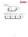
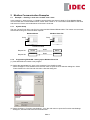
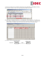
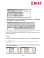
FC5A Modbus Communication Tutorial
1
2
System Setup ..............................................................................................................................................2
1.1
1:1 network..........................................................................................................................................2
1.2
1:N network (Up to 31 Slaves) ............................................................................................................2
Modbus Communication Examples ..........................................................................................................3
2.1
Example 1 - Reading 1 word and 1 bit data from a slave ...................................................................3
2.1.1 System Setup.........................................................................................................................3
2.1.2 Programming WindLDR - Setting up the Modbus Slave #15 ................................................3
2.1.3 Programming WindLDR - Setting up the Modbus Master......................................................5
2.1.4 Check the system...................................................................................................................8
2.2
Example 2 - Reading multiple words and bits data from a slave........................................................9
2.2.1 System Setup.........................................................................................................................9
2.2.2 Programming WindLDR - Setting up the Modbus Slave #15 ..............................................10
2.2.3 Programming WindLDR - Setting up the Modbus Master....................................................10
2.2.4 Check the system.................................................................................................................10
2.3
Example 3 - Writing 1 word and 1 bit to a slave ...............................................................................12
2.3.1 System Setup.......................................................................................................................12
2.3.2 Programming WindLDR - Setting up the Modbus Slave #15 ..............................................13
2.3.3 Programming WindLDR - Setting up the Modbus Master....................................................13
2.3.4 Check the system.................................................................................................................13
2.4
Example 4 - Using Request Execution Relay ...................................................................................15
2.4.1 System Setup.......................................................................................................................15
2.4.2 Programming WindLDR - Setting up the Modbus Slave #15 ..............................................16
2.4.3 Programming WindLDR - Setting up the Modbus Master....................................................16
2.4.4 Programming WindO/I NV2 - Setting up the Screen ...........................................................17
2.4.5 Check the system.................................................................................................................18
2.5
Example 5 - Changing the preset values of Timers or Counters......................................................20
2.5.1 System Setup.......................................................................................................................20
2.5.2 Programming WindLDR - Setting up the Modbus Slave #15 ..............................................20
2.5.3 Programming WindLDR - Setting up the Modbus Master....................................................21
2.5.4 Check the system.................................................................................................................21
2.6
Example 6 - Communication Verification ..........................................................................................22
2.6.1 System Setup.......................................................................................................................22
2.6.2 Programming WindLDR - Setting up the Modbus Slave #15 ..............................................22
2.6.3 Programming WindLDR - Setting up the Modbus Master....................................................22
2.6.4 Check the system.................................................................................................................23
2.7
Example 7 - Simple 1:N Communication ..........................................................................................24
2.7.1 System Setup.......................................................................................................................24
2.7.2 Programming WindLDR - Setting up the Modbus Slave #2.................................................24
2.7.3 Programming WindLDR - Setting up the Modbus Slave #13 ..............................................24
2.7.4 Programming WindLDR - Setting up the Modbus Slave #31 ..............................................25
2.7.5 Programming WindLDR - Setting up the Modbus Master....................................................25
2.7.6 Check the system.................................................................................................................26
IDEC Elektrotechnik GmbH
20537 Hamburg . Wendenstraße 331 . Tel. (040) 25 30 54-0 . Fax (040) 25 30 54 24 . [email protected] . www.idec.de
1 System Setup
1.1
1:1 network
1:1 network can be established with either RS232C or RS485.
Modbus Master
Modbus Slave
Port 2
Port 2
RS2323C/RS485
1.2
1:N network (Up to 31 Slaves)
1:N network can be established with either RS485. Up to 31 Modbus slaves can be connected to a master.
Modbus Master
Modbus Slave
Modbus Slave
Port 2
Port 2
RS485
Seite 2
Modbus Slave
Port 2
2 Modbus Communication Examples
2.1
Example 1 - Reading 1 word and 1 bit data from a slave
In the example 1, steps to set up 1:1 Modbus communication are shown in detail. A FC5A Modbus Master
communicates with a FC5A Modbus Slave, whose slave number is 15. The master reads D8057 of the slave
and stores it in D0100, and reads M8121 and stores it in M0100.
2.1.1
System Setup
The port 2 of two FC5A All-in-one CPUs is connected with RS232C/RS485 cable. The master communicates
with the slave using two communication requests.
Modbus Master
Modbus Slave #15
Port 2
Port 2
RS2323C/RS485
2.1.2
Request #1
D0100
Read
D8057
Request #2
M0100
Read
M8121
Programming WindLDR - Setting up the Modbus Slave #15
(1) Start WindLDR and create a new program.
(2) Select the appropriate PLC type. In this example, FC5A-C24R2 is used.
Select Configure > PLC Selection from the main menu to open the PLC Selection dialog box. Select
FC5A-C24R2 in the PLC list and click OK to close the dialog box.
(3) Select Configure > Function Area Settings… from the main menu to open the Function Area Settings
dialog box, and then select the Communication tab.
Seite 3
(4) Select Modbus RTU Slave from the dropdown list for the Port 2, and then Communication Parameters
dialog box appears. Input “15” as the Slave Number and click OK to close the dialog box, and then click
OK to close the Function Area Settings dialog box.
(5) Connect the FC5A to be the Modbus Slave #15 to the PC and select Online > Download Program… from
the main menu to open the Download Program dialog box. Click Download button to start downloading
the program.
(6) Program Download confirmation dialog box will appear, and the setup for the Modbus Slave has been
finished.
Seite 4
2.1.3
Programming WindLDR - Setting up the Modbus Master
(1) Create a new program and select the appropriate PLC type. In this example, select FC5A-C10R2.
(2) Select Configure > Function Area Settings… from the main menu to open the Function Area Settings
dialog box, and then select the Communication tab.
(3) Select Modbus RTU Master from the dropdown list for the Port 2, and then Modbus Master Request
Table dialog box appears.
(4) Define the first communication request.
Modbus Master
Request #1
D0100
Modbus Slave
Read
D8057
(5) Click on the cell of the Function Code of the Request #1 in the dialog box, and then the dropdown list will
appear. From the dropdown list, select the 03 Read Holding Register.
Seite 5
Note: Modbus Device, Modbus Address, and Function Code
When using FC5A as a Modbus Slave device, Modbus Addresses are assigned to all the operands available
on FC5A. In the page 30-9 of the FC5A User’s Manual, the Address Map of the FC5A Modbus Slave is
shown as below.
For example, special data registers D8000 thru D8499 are considered the Holding Registers, the Modbus
Addresses 408001 thru 408500 are assigned to these operands, and the Function Code 3, 6, or 16 can be
used to manipulate these operands.
In order to obtain the Modbus address of MicroSmart operands, the formula shown below can be used. For
example, the Modbus address of D8057 can be calculated as follows.
D8057 (MicroSmart Operand) = (8057 - 8000) + 408001 = 408058 (Modbus Address).
Seite 6
To reduce the calculation effort, the Modbus Address table “FC5A_ModbusSlave_AddressMap.xls” showing
all the operands available on FC5A and corresponding Modbus address is provided.
(6) Input “D100“ in the Master Allocation No., “1“ in the Data Size, “15“ in the Slave No., and “408058” in the
Slave Address. The setup for the communication request #1 has been completed. The 1 word data at the
address 408058 of the Modbus Slave #15 is read out and stored in D0100 of the Modbus Master.
(7) Define the second communication request.
Modbus Master
Request #2
M0100
Modbus Slave
Read
Seite 7
M8121
(8) To obtain the Modbus Address of M8121, select Special Internal Relay sheet in the Modbus Address
table and look up the M8121.
(9) Click on the cell of the Function Code of the Request #2 in the dialog box, and then select the 01 Read
Coil Status from the dropdown list. Then, Input “M100“ in the Master Allocation No., “1“ in the Data Size,
“15“ in the Slave No., and “009098” in the Slave Address.
(10) The setup for the communication request #2 has been completed. The 1 bit data at the address 009098
of Modbus Slave #15 is read out and stored in M0100 of the Modbus Master.
(11) Click OK to close the Modbus RTU Request Table dialog box, and then click OK to close the Function
Area Settings dialog box.
(12) Connect a FC5A to be the Modbus Master to the PC and select Online > Download Program… from the
main menu to open the Download Program dialog box. Click Download button to start downloading the
program.
(13) Program Download confirmation dialog box will appear, and the setup for the Modbus Master has been
finished.
2.1.4
Check the system
(1) Connect the PC to the Modbus Master and select Online > Monitor from the main menu to start the
Monitor mode.
(2) Select Online > Point Write to open a Point Write dialog box, and then input D100 to monitor. On the
Modbus Slave, change D8057 with the Analog Potentiometer 1 and see the D100 of the Modbus Master
changes between 0 through 255.
Seite 8
(3) Select Online > Direct Set/Reset to open a Direct Set/Reset dialog box, and then input M100 to monitor.
M100 turns on and off every second.
2.2
Example 2 - Reading multiple words and bits data from a slave
In the example 2, a FC5A Modbus Master communicates with a FC5A Modbus Slave, whose slave number is
15. The master reads D8057 and D8058 of the slave and stores it in D0100 and D0101, and reads M8121
through M8123 and stores them in M0100 through M0102.
2.2.1
System Setup
The port 2 of two FC5A All-in-one CPUs is connected with RS232C/RS485 cable. The master communicates
with the slave using two communication requests.
Modbus Master
Modbus Slave #15
Port 2
Port 2
RS2323C/RS485
Request #1
Request #2
D0100
Read
D8057
D0101
D8058
M0100
M8121
M0101
Read
M0102
M8122
M8123
Seite 9
Note: Data Size of the Function Code
Each Function Code has the certain range of the Data Size for the communication. For example, if you use
the Function Code 03 Read Holding Registers, you can read a maximum of 64 words data from a slave at a
time. Although FC5A Modbus master supports the Data Size shown in the table below, Modbus slave devices
may have different range of Data Size.
2.2.2
Programming WindLDR - Setting up the Modbus Slave #15
Nothing has to be changed from the example 1.
2.2.3
Programming WindLDR - Setting up the Modbus Master
(1) Open the Modbus Master program of the example 1 and open the Modbus Master Request Table dialog
box.
(2) Change the Data Size of the Request #1 from 1 to 2 and of the Request #2 from 1 to 3.
2.2.4
Check the system
(1) Connect the PC to the Modbus Master and select Online > Monitor from the main menu to start the
Monitor mode.
Seite 10
(2) Select Online > Point Write to open a Point Write dialog box, and then input D100 and D101 to monitor.
On the Modbus Slave, change D8057 with the Analog Potentiometer 1 and see that the D100 of the
Modbus Master changes between 0 through 255. Similarly, change the Analog Potentiometer 2 and see
that D101 changes.
(3) Select Online > Direct Set/Reset to open a Direct Set/Reset dialog box, and then input M100, M101, and
M102 to monitor. See that M100, M101, and M102 turn on and off.
Seite 11
2.3
Example 3 - Writing 1 word and 1 bit to a slave
In the example 3, a FC5A Modbus Master communicates with a FC5A Modbus Slave, whose slave number is
15. The master writes D50 to the D20 of the slave, and writes M50 to Q2 of the slave. The slave outputs Q0
when D20 is equal to 5000.
2.3.1
System Setup
The port 2 of two FC5A All-in-one CPUs is connected with RS232C/RS485 cable. The master communicates
with the slave using two communication requests.
Modbus Master
Modbus Slave #15
Port 2
Port 2
RS2323C/RS485
Request #1
D50
Write
Request #2
M50
Write
D20
(400021)
Q2
(000003)
Note: Function Code
FC5A Modbus Master supports 8 Function Codes as shown below (30-5 in the FC5A User’s Manual). Though
the Function Codes 05, 06, 15, or 16 can be used to write values to Modbus Slave devices, you need to
make sure that which function codes the Modbus Slave devices support. In fact, some Modbus devices do
not support Function Code 15 and 16.
For example, FC5A Modbus Slave supports all the 8 function codes, and you need to select function code
according to the operand type you want to access. If you want to read the status of I0, you need to use “02
Read Input Status”, and if you want to write values to D1, you need to use either “06 Preset Single Register”
or “16 Preset Multiple Registers.”
Seite 12
2.3.2
Programming WindLDR - Setting up the Modbus Slave #15
(1) Create a new file and configure the function area settings as shown in the example 1.
(2) Create the ladder program as shown below. When D20 is equal to 5000, Q0 turns on.
(3) Download the program to the Modbus Slave.
2.3.3
Programming WindLDR - Setting up the Modbus Master
(1) Create a new file and open the Modbus RTU Master Request Table.
(2) Input the two communication requests according to the specification. After inputting the all parameters,
Modbus RTU Master Request Table becomes as shown below.
(4) Close the Request Table and Function Area Settings dialog boxes, and then download the program to
the Modbus Master.
2.3.4
Check the system
(1) Connect the PC to the Modbus Master and select Online > Monitor from the main menu to start the
Monitor mode.
Seite 13
(2) Select Online > Point Write to open a Point Write dialog box, and then input D50 to monitor. Change the
D50 value and see if Q0 of the Modbus Slave turns on when D50 of Modbus Master is equal to 5000.
(3) Select Online > Direct Set/Reset to open a Direct Set/Reset dialog box, and then input M50 to monitor.
Set/reset M50 and see if Q2 of the Modbus Slave turns on/off accordingly.
Seite 14
2.4
Example 4 - Using Request Execution Relay
In the example 4, a FC5A Modbus Master communicates with a FC5A Modbus Slave, whose slave number is
15. The master writes D50 to D20 and M50 to Q2 when M0100 turns on. The slave outputs Q0 when D20 is
equal to 5000. A touch screen also monitors the Modbus Slave thorough the port 1 of the slave and changes
the value of D20 and Q2.
2.4.1
System Setup
Modbus Master
Port 2
HG touch screen
Modbus Slave #15
Port 2
RS2323C/RS485
Request #1
D50
Write
D20
(400021)
Read/Write
Numerical
Input
M50
Write
Q2
(000003)
Read
Pilot Lamp
Request #2
Write
Bit Button
(Toggle)
Note: Modbus Master Request Table and Request Execution Relay
When the Request Execution Relay is disabled, all the registered requests in the Request Table are executed
repeatedly. For example, if 4 communication requests are registered as below, request 1 through 4 are
executed in order, and when the request #4 is completed, FC5A starts over from the request #1. As a result,
even if the value in D20 of the Modbus Slave #15 is changed with the touch screen, the value will be overwritten by the Modbus Master.
When the Request Execution Relay is enabled, internal relays are assigned to all the communication
requests registered in the Request Table. The communication requests are executed only when
corresponding internal relays are ON. For example, when M200 is assigned as the Request Execution Relay,
4 internal relays starting from M200 are assigned to the communication requests as below. And only when
M202 is ON, the Modbus Master executes the communication request #3. Therefore, when M202 is OFF, the
value in D20 of the Modbus Slave #15 can be changed with the touch screen without over-written by the
Modbus Master.
Seite 15
2.4.2
Programming WindLDR - Setting up the Modbus Slave #15
The setup for the Modbus Slave is the same as the example 3.
2.4.3
Programming WindLDR - Setting up the Modbus Master
(1) Create a new file and open the Modbus RTU Master Request Table.
(2) Input the two communication requests according to the specification. And then click on Use and input
M0200 in the Request Execution Internal Relay setting. After inputting the all parameters, Modbus RTU
Master Request Table becomes as shown below.
(5) Close the Request Table and Function Area Settings dialog boxes.
(6) Create a ladder program as shown the picture below. When M100 is turned on, M200 is set, and when
M101 is turned on, M201 is set.
Note: When a Request Execution Relay is turned on, the corresponding communication request is executed,
and the Request Execution Relay is automatically turned off when the request is completed. Therefore, when
a Request Execution Relay is turned on with a SET instruction following a SOTU/D instruction as shown
above, the communication request is executed just one time.
(7) Download the program to the Modbus Master.
Seite 16
2.4.4
Programming WindO/I NV2 - Setting up the Screen
(1) Create a new project and select an appropriate screen type and the Host interface driver.
(2) Create a Numerical Input and input “D 20” as the Destination Device.
(3) Create a Pilot Lamp and input “Q 2” as the Device.
Seite 17
(4) Create a Bit Button and input “Q 2” as the Destination Device and select “Toggle” as the Action Mode.
(5) Download the project to the Touch Screen connected to the port 1 of the Modbus Slave #15.
2.4.5
Check the system
(1) Connect the PC to the Modbus Master and select Online > Monitor from the main menu to start the
Monitor mode.
(2) Select Online > Point Write to open a Point Write dialog box, and then input D50 to monitor. Change the
D50 value to 5000 and confirm that Q0 of the slave does not turn on, and the D20 value of the slave
shown on the touch screen remains 0.
(3) Turn on M100 of the master, and then Q0 of the Slave turns on and the D20 value shown on the touch
screen becomes 5000.
Seite 18
(4) Change the D20 value to other value such as 9999 using the Numerical Input on the screen, and the Q0
of the slave turns off. Change the D20 value back to 5000, and then Q0 turns on again.
(5) Select Online > Direct Set/Reset to open a Direct Set/Reset dialog box, and then input M50 to monitor.
Set/reset M50 and confirm that Q2 of the slave does not turn on, and the Pilot Lamp on the touch screen
also does not turn on.
(6) Turn on M101 of the master, and then Q2 of the slave turns on, and the Pilot Lamp on the touch screen
also turns on.
(7) Toggle Q2 using the Bit Button on the screen and see that Q2 of the slave and the Pilot Lamp on the
screen turn off. Toggle Q2 again, then Q2 and the Pilot Lamp turn on.
Note:
If you want to execute communication requests repeatedly when the Request Execution Relay is enabled,
you have to program SET instructions following M8125 (In-operation Output) to set the relays. For example, if
you program as below, the communication request #1 is executed only when M100 is turned on, but the
communication request #2 is executed repeatedly as long as the PLC is running.
Seite 19
2.5
Example 5 - Changing the preset values of Timers or Counters
In this example, a method to change the preset value of a TIM instruction in a Modbus slave from the Modbus
Master. A FC5A Modbus Master communicates with a FC5A Modbus Slave, whose slave number is 15. The
master writes D50 to D20. Q0 of the slave is turned on D20 ms later after I0 turns on.
2.5.1
System Setup
Modbus Master
Modbus Slave #15
Port 2
Port 2
RS2323C/RS485
Request #1
D50
Write
D20
(400021)
Note:
As shown below (FC5A Modbus Slave Address Map in 30-5 of FC5A User’s Manual), only the Function Code
3 can be used to access the preset values of timers and counters. As the Function Code 3 is “03 Read
Holding Registers,” you can read these values but cannot write values to them.
2.5.2
Programming WindLDR - Setting up the Modbus Slave #15
(1) Create a new file and configure the function area settings as shown in the example 1.
(2) Create a ladder program as shown below. When I0 turns on, TIM T0 instruction starts, and D20 ms later,
Q0 is turned on.
(3) Download the program to a FC5A to be the Modbus Slave #15.
Seite 20
2.5.3
Programming WindLDR - Setting up the Modbus Master
(1) Create a new file and open the Modbus RTU Master Request Table and configure the Request #1 as
follows.
(2) Close the dialog box and download the program to a FC5A to be the master.
2.5.4
Check the system
(1) Connect the PC to the Modbus Master and select Online > Monitor from the main menu to start the
Monitor mode.
(2) Select Online > Point Write to open a Point Write dialog box, and then input D50 to monitor. Write 0 to
D50, and then turn on I0 of the slave and see that Q0 turns on right after I0 turns on.
(3) Write 30 to D50, and then turn on I0 of the slave and see that Q0 turns on about 3 sec after I0 turns on.
Seite 21
2.6
Example 6 - Communication Verification
This example shows a method to see whether the communication requests completed successfully or not. A
FC5A Modbus Master communicates with a FC5A Modbus Slave, whose slave number is 15. The master
writes D50 to D20 when M0 is turned on.
2.6.1
System Setup
Modbus Master
Modbus Slave #15
Port 2
Port 2
RS2323C/RS485
Request #1
2.6.2
D50
Write
D20
(400021)
Programming WindLDR - Setting up the Modbus Slave #15
Take the same steps as shown in the Example 1.
2.6.3
Programming WindLDR - Setting up the Modbus Master
(1) Create a new file and configure the Modbus Master Request Table as below. Then close the Function
Area Settings dialog box.
(2) Create the ladder program as shown below. When an input M000 turns on, M100, Request execution
relay for the request #1, is turned on, and Q0 and Q1 are reset. When the request #1 is completed, M100
is turned off automatically. Then, if the communication succeeds, Q0 turns on, and if the communication
fails, Q1 turns on.
Descriptions for the operands used in the program.
Operand Description
M0000
Execute the communication request #1.
M0100
The communication execution relay for the request #1.
When this bit is turned on, the communication request #1 is executed, and this
bit is turned off automatically when the communication request #1 is completed.
M8005
When a communication request is completed, M8005 turns on for 1 scan time if
any communication errors happen during the communication.
Q0000
Turns on when the communication request #1 succeeded.
Q0001
Turns on when the communication request #1 failed.
Seite 22
Program
2.6.4
Check the system
(1) Connect the PC to the Modbus Master and select Online > Monitor from the main menu to start the
Monitor mode.
(2) Double click on M0000 and see that the communication is completed successfully, and Q0 is turned on.
Turn off the slave and double click on M0000 again, and see that the communication failed, and Q1 is
turned on.
Succeeded
Failed
Seite 23
2.7
Example 7 - Simple 1:N Communication
This example shows steps to set up a 1:N Modbus network. A FC5A Modbus Master communicates with 3
FC5A Modbus Slaves whose slave numbers are 2, 13, and 31. The master writes D100 to D50 of all the
slaves. The slave #2 adds 100 to D50 and stores the result in D51, the slave #13 subtracts D50 by 100 and
stores the result in D51, and the slave #31 doubles D50 and stores the result in D51. The master reads D51
of each slaves and stores them in D101 through D103.
2.7.1
System Setup
Modbus Master
Modbus Slave #13
Modbus Slave #2
Port 2
Modbus Slave #31
Port 2
Port 2
RS485
Request #1
D100
Request #2
D101
Request #3
D100
Request #4
D102
Request #5
D100
Request #6
D103
2.7.2
Write
Read
D50
D51
D50
Write
D51
Read
Write
Read
D50
D51
Programming WindLDR - Setting up the Modbus Slave #2
(1) Create a new file, and select Modbus RTU Slave for the Port 2 and input the slave number 2 in the
Function Area Settings dialog box as shown in the example 1.
(2) Create the ladder program as below. The value in D50 is incremented by 100, and the result is stored in
D51.
(3) Download the program to a FC5A to be a Modbus Slave #2.
2.7.3
Programming WindLDR - Setting up the Modbus Slave #13
(1) Create a new file, and select Modbus RTU Slave for the Port 2 and input the slave number 13 in the
Function Area Settings dialog box as shown in the example 1.
(2) Create the ladder program as below. The value in D50 is decremented by 100, and the result is stored in
D51.
Seite 24
(3) Download the program to a FC5A to be a Modbus Slave #13.
2.7.4
Programming WindLDR - Setting up the Modbus Slave #31
(1) Create a new file, and select Modbus RTU Slave for the Port 2 and input the slave number 31 in the
Function Area Settings dialog box as shown in the example 1.
(2) Create the ladder program as below. The value in D50 is doubled, and the result is stored in D51.
(3) Download the program to a FC5A to be a Modbus Slave #31.
2.7.5
Programming WindLDR - Setting up the Modbus Master
(1) Create a new file, and select Modbus RTU Master for the Port 2 and register the communication requests
as shown below.
(2) Close the Function Area Settings dialog box and download the program to a FC5A to be the master.
Seite 25
2.7.6
Check the system
(1) Connect the PC to the Modbus Master and select Online > Monitor from the main menu to start the
Monitor mode.
(2) Select Online > Point Write to open a Point Write dialog box, and then input D100, D101, D102, and
D103 to monitor. Write 500 to D100 and see that 600 is stored in D101, 400 is stored in D102, and 1000
is stored in D103.
(3) Write 1500 to D100 and see that 1600 is stored in D101, 1400 is stored in D102, and 3000 is stored in
D103.
Note: Broadcast
A broadcast communication request can be executed to write the same value to all the slaves in the network
by assigning the slave No. 0 to the communication request. Note that if the broadcast is used, the slaves do
not send replies to the master; therefore, the master cannot detect any communication errors.
For example, the communication requests of the example 7 can be simplified using a broadcast request as
below.
Seite 26